EP4092404A1 - Lecteur de microdisques - Google Patents
Lecteur de microdisques Download PDFInfo
- Publication number
- EP4092404A1 EP4092404A1 EP22171870.3A EP22171870A EP4092404A1 EP 4092404 A1 EP4092404 A1 EP 4092404A1 EP 22171870 A EP22171870 A EP 22171870A EP 4092404 A1 EP4092404 A1 EP 4092404A1
- Authority
- EP
- European Patent Office
- Prior art keywords
- area
- microplate reader
- housing
- microplate
- system area
- Prior art date
- Legal status (The legal status is an assumption and is not a legal conclusion. Google has not performed a legal analysis and makes no representation as to the accuracy of the status listed.)
- Granted
Links
Images
Classifications
-
- G—PHYSICS
- G01—MEASURING; TESTING
- G01N—INVESTIGATING OR ANALYSING MATERIALS BY DETERMINING THEIR CHEMICAL OR PHYSICAL PROPERTIES
- G01N21/00—Investigating or analysing materials by the use of optical means, i.e. using sub-millimetre waves, infrared, visible or ultraviolet light
- G01N21/17—Systems in which incident light is modified in accordance with the properties of the material investigated
- G01N21/25—Colour; Spectral properties, i.e. comparison of effect of material on the light at two or more different wavelengths or wavelength bands
- G01N21/251—Colorimeters; Construction thereof
- G01N21/253—Colorimeters; Construction thereof for batch operation, i.e. multisample apparatus
Definitions
- the present invention relates to a microplate reader comprising a housing, inside which a sample area and a system area are formed, the sample area including a receiving device for receiving a microplate having a plurality of wells, wherein in the sample area and / or in the system area optical element for detecting an optical radiation is arranged on each individual well of a microplate accommodated in the receiving device, the receiving device and the optical element being arranged such that they can move in relation to one another in order to position the accommodated microplate with respect to the optical element for successive measurements on different wells, and wherein the system area comprises at least one measurement and/or analysis module for the optical radiation.
- a microplate is a sample carrier for carrying out photometric or other measurements, the sample carrier having a large number of wells which are arranged at regular intervals and in which the individual samples are formed.
- a microplate reader is used to "read" microplates by carrying out photometric measurements on the individual depressions, also known as "wells".
- the microplate reader has measurement and analysis modules, such as a photomultiplier, by means of which the luminescence, fluorescence and/or absorption of the samples in the wells is determined.
- the microplate is inserted into a receiving device which can be moved in the X and Y directions via a positioning mechanism. For the sequential reading of the individual depressions, they are brought one after the other into the detection area of the optical element by the positioning mechanism.
- the photometric examination of samples in a microplate with a microplate reader is used in a wide range of applications, including the detection of biological, chemical, biochemical or physical reactions of the samples.
- additional functions may be required to trigger, maintain or otherwise support appropriate reactions.
- measurement sensors may also be required for additional measurement functions.
- the microplate is arranged in a sample area within the microplate reader, whereby the microplate can be heated if necessary.
- the microplate reader can be supplied with a gaseous medium in its interior, the gaseous medium preferably not being air. In this way, the gas atmosphere required for certain applications as well as constant test conditions for the analysis of the samples can be created.
- the measurement and/or analysis modules for detecting the optical radiation emitted or absorbed by the samples are predominantly arranged in a system area which is preferably arranged as close as possible to the samples.
- the measurement accuracies of the measurement and/or analysis modules can be increased if their components can be cooled and the optical paths can be kept short.
- a microplate reader of the type mentioned at the outset provides for a device for convective cooling to be arranged in the system area, with at least one guide element being arranged between the system area and the sample area in order to direct a flow of the convective cooling, in particular in the system area.
- the at least one guide element between the system area and the sample area allows the convective cooling, in particular in the system area, to be guided in a targeted manner, so that the measurement and/or analysis modules in the system area are optimally flowed around by the convective cooling and cooled accordingly.
- the cooling of the measurement and/or analysis modules improves the measurement accuracy during the measurements, with the flow of the convective cooling, in particular in the system area, being guided by the at least one guide element initially not having any significant effect on the sample area.
- the measurement and/or analysis modules are, in particular, an optical detector and/or an excitation means.
- the measurement and/or analysis modules can be a photomultiplier, a flash lamp or a light source.
- the optical element is in particular an adjustable objective, a lens, a diaphragm and/or an optical waveguide.
- a heating device for heating the microplate and in particular the optical element is arranged in the sample area.
- the microplate as well as the optical element and optionally further elements in the sample area can be heated in a targeted manner, for example in order to trigger corresponding reactions in the samples, which only take place in a specific temperature range.
- the microplate, and in particular also the entire sample area can be heated to a temperature of typically up to 60° C. by the heating device.
- the heating device preferably comprises a lower heating plate and/or an upper heating plate, which are arranged below and/or above the microplate.
- the upper heating plate has a passage opening through which the optical radiation can pass, starting from the individual wells of the microplate, in the direction of the optical element.
- the housing preferably has a gas inlet, via which the housing, in particular the sample area and the system area, are completely flooded with a gaseous medium.
- a gaseous medium By introducing a gaseous medium into the housing in a targeted manner, the conditions required for specific applications, such as the analysis of biological cells, are created in the sample area. In addition, an undesired or unintentional reaction of the samples in the microplate can be avoided.
- nitrogen and/or carbon dioxide are used as the gaseous medium.
- a specific mixing ratio such as a (residual) oxygen content, can also be set through the gas inlet, and changes in the mixture over time in the housing can be achieved.
- a preferred embodiment of the microplate reader is characterized in that the at least one guiding element or several guiding elements together essentially cover the sample area.
- the sample area in which the samples can also be heated, is essentially shielded and separated from the system area.
- different conditions can exist in the system area as well as in the sample area.
- the sample area can be heated independently of the cooling in the system area.
- the guide element has at least one opening to the sample area and/or is arranged in such a way as to form an opening with a component of the microplate reader.
- the component of the microplate reader is in particular a measurement and/or analysis module, a carrier plate, a reinforcement or stiffening element or an electronic component, for example a printed circuit board.
- several guide elements are arranged in sections in such a way that at least one opening is formed between the system area and the sample area.
- the sample area can be influenced in a targeted manner by means of the cooling device for convective cooling arranged in the system area, with the influence of the cooling on the sample area being controlled by the appropriate arrangement of the guide element or guide elements in the microplate reader and the design of the at least one opening to the sample area can be determined.
- the thermal conditions in the sample area can be influenced and even adjusted by means of a cooling device in the system area.
- the cooling device arranged in the system area thus enables both the sample area and the system area to be cooled or correspondingly tempered.
- a fan in particular a radial fan, is arranged in the area of the at least one opening.
- the gaseous medium in the sample area can be directed into the system area by means of the fan and the sample area can thus also be actively cooled by means of the cooling device arranged in the system area.
- the fan can only be switched on when required. In addition, this can take place more quickly thanks to the fan compared to cooling that is only implemented via convection between the system area and the sample area. Thanks to its design, the use of a radial fan also enables convective cooling between the system area and the the sample area essentially prevents. As a result, when using a radial fan, a closure element in front of the corresponding opening can also be dispensed with.
- An opening area of the at least one opening can preferably be changed.
- the thermal conditions in the sample area can be specifically influenced by the convective cooling through the opening.
- the opening area of the opening can be changed and, in particular, can be closed by means of a closure element, the closure element preferably being a slide or a flap.
- the sample area can thus be specifically separated from the system area by the closure element, so that convective cooling no longer takes place via the at least one opening.
- the corresponding opening area of the opening between the system area and the sample area can be adjusted by the closure element and the convective cooling between the system area and the sample area can thus be changed accordingly.
- the opening area is up to 100 cm 2 , preferably up to 60 cm 2 , particularly preferably up to 40 cm 2 , in particular 35 cm 2 .
- the small opening area compared to the base area of the microplate reader, which is approximately 20 to 100 times the opening area, allows the sample chamber to be heated without significantly influencing the conditions in the system area.
- the conditions in the sample area as well as in the system area can be designed specifically and also differently. However, a targeted influencing of the sample area by the cooling is also made possible.
- a preferred embodiment of the microplate reader is characterized in that the at least one guide element has or forms at least two openings to the sample area, which are preferably formed at different heights above a base of the housing.
- convective cooling can also be achieved actively with support from the fan arranged in front of an opening or also passively in the sample area. This is achieved by arranging the openings at different heights relative to a bottom of the housing of the microplate reader further supported.
- a flow from the sample area into the system area can take place at the opening arranged closer to the bottom, whereas a flow of convective cooling takes place from the system area into the sample area at the opening arranged further away from the bottom of the housing.
- flows can also be formed in the sample area, which allow solvent vapors arising in the sample area, for example due to evaporation of a solvent in the individual wells of the microplate, to be discharged from the sample area into the system area.
- the cooling device preferably includes a flow fan, by means of which the convective cooling in the system area is supported.
- the flow fan is preferably arranged at an outlet of the cooling device.
- the cooling device is preferably placed in the system area in such a way that the flow of the convective cooling is formed as a circuit, in particular in the system area.
- the formation of a circuit directs the flow in a targeted manner, particularly in the system area, and enables effective cooling of the measurement and/or analysis modules in the system area.
- the cooling device has an outlet and an inlet, which are preferably arranged such that a cooled flow of the circuit emanating from the cooling device makes an angle in a range from 60° to 120° to a heated flow of the circuit entering the cooling device °, preferably form about 90 ° to each other.
- the circuit of the flow of the convective cooling can be guided through the system area in such a way that the special arrangement of the inlet and the outlet avoids a crossing of the flow.
- the measurement and/or analysis module or modules that have a high output and generate a corresponding amount of heat and/or require high temperature stability and/or have a higher performance when cooled are arranged first in the flow circuit.
- high temperature stability can be achieved in the individual measurement and/or analysis modules and/or by a direct Cooling the performance of the individual measurement and / or analysis module can be increased.
- by arranging the high-performance measurement and/or analysis modules first in the cooling circuit and thus closer to the outlet of the cooling device they can be specifically cooled and the heat generated can be dissipated accordingly. This improves the measurement accuracy of the measurement and/or analysis modules overall.
- Targeted cooling of these measurement and/or analysis modules avoids a build-up of heat in certain areas of the system. Furthermore, arranging this measurement and/or analysis module first in the cooling circuit means that the flow, which is still cool, can absorb a higher quantity of heat and thus enables better cooling of the measurement and/or analysis modules.
- the measurement and/or analysis module or modules are arranged in such a way that the cooled flow flows directly against them.
- the direct flow to the corresponding measurement and/or analysis modules allows them to be cooled in a targeted manner.
- the directly flowed measurement and/or analysis modules are in particular those measurement and/or analysis modules that have a high output and thus generate heat and/or require high temperature stability and/or have a higher performance when cooled.
- the cooling device comprises an evaporator and a condenser and preferably a cooling fan, with the evaporator being arranged in the housing and the condenser and the cooling fan outside the housing, in particular on the housing itself, preferably in an add-on element.
- the condenser and in particular the cooling fan outside the housing in particular outside a thermally insulated housing, disturbing currents can be avoided and a better cooling effect can be achieved.
- a cold side of the cooling device, which in particular includes the evaporator is therefore arranged inside the housing, whereas a warm side of the cooling device, which in particular includes the compressor, is arranged outside of the housing, in particular in the add-on element.
- a condensate drain is preferably arranged below the evaporator in order to collect condensate arising on the evaporator and to drain it out of the housing in order to preferably evaporate it directly into the ambient air.
- the formation of condensate within the system area and/or the sample area can be avoided by the targeted drainage of the condensate that forms on the evaporator, so that an influence of the measuring systems, in particular the measuring and analysis modules, by condensate can be almost completely ruled out.
- the cooling of the gaseous medium in the housing at the evaporator causes the medium to be dehumidified.
- solvent vapors that have entered the system area from the sample area can condense on the evaporator or be bound in the condensate and thus be discharged from the housing via the condensate drain.
- the condensate drain can also prevent the condensate that forms on the evaporator from dripping onto a component of the system area and/or the sample area or condensing there, which would negatively affect the measurements and the measurement accuracy.
- the housing is preferably thermally insulated from the environment, in particular from the add-on element.
- the housing is preferably thermally insulated from the environment, in particular from the add-on element.
- the relative humidity inside the housing should be permanently less than 70% in order to avoid the formation of condensate on the components of the microplate reader, in particular on the measurement and/or analysis modules, and thereby influencing the measurement results.
- the sample region can be cooled in a targeted manner during and/or also after measurements have been carried out on a microplate.
- Certain thermal test conditions in particular in connection with the heating device, can thus be set in a targeted manner.
- the microplate reader is ready for use again more quickly, for example to analyze another microplate, by cooling the sample area that may have heated up.
- a microplate reader 1 according to the invention is shown in a side sectional view.
- the microplate reader 1 comprises a housing 2 which essentially completely encloses the microplate reader 1 and is thermally insulated from the environment.
- a housing 2 which essentially completely encloses the microplate reader 1 and is thermally insulated from the environment.
- an insert 12 via which a microplate 6 is introduced into a sample area 3 of the microplate reader 1 by means of a receiving device 5 .
- the insert 12 in the housing 2 is completely closed again, so that the microplate reader 1 is essentially sealed off from the environment.
- the microplate 6 itself has a large number of wells into which the samples to be examined by means of the microplate reader 1 are introduced.
- an optical element 7 is arranged in the sample area 3, by means of which the optical radiation is detected during the analysis of the individual samples in the respective individual wells of the microplate 6.
- the optical element is an adjustable objective, a lens, a diaphragm and/or an optical waveguide.
- the optical element 7 can also be arranged in the system area 4 and the optical radiation reach the optical element 7 via a passage.
- the optical element can be arranged in this passage.
- the sample area 3 comprises an injector 8, by means of which further reagents can be supplied to the samples in the wells of the microplate 6, if required.
- the heating device 10 In the area of the microplate 6 and the optical element 7 and the injector 8 there is a heating device 10 by means of which the microplate 6 or the samples formed in the wells of the microplate 6 can be heated to a desired temperature.
- the heating device 10 comprises a lower heating plate 10a and an upper heating plate 10b, which are arranged below and above the microplate 6, respectively.
- a passage opening is formed in the upper heating plate 10b, through which the optical radiation passes from a depression in the microplate 6 in the direction of the optical element 7 .
- the heater 10 also allows both the optical element 7 and the injector 8 to be heated together with the microplate 6 for optimal function.
- a gas inlet 9 via which a gaseous medium, in this case nitrogen, is fed into the housing 2 of the microplate reader 1 .
- the entire housing 2 can be flooded with the gaseous medium or a certain mixing ratio, such as a (residual) oxygen content, and changes in the mixture over time can be achieved.
- the microplate reader 1 also includes a system area 4 in which a plurality of measurement and/or analysis modules 11, 11a, 11b, 11c for evaluating the radiation detected by the optical element 7 are arranged.
- the luminescence, fluorescence and/or absorption of the samples in the wells of the microplate 6 is determined by means of the measurement and/or analysis modules 11, 11a, 11b, 11c, as a result of which the individual samples can be characterized accordingly.
- the measurement and/or analysis modules 11, 11a, 11b, 11c include two or four photomultipliers 11a, a flash lamp 11b, a light source 11c and other measurement and/or analysis modules 11, which are distributed in the system area 4.
- the measurement and/or analysis modules 11, 11a require high temperature stability since they have a higher performance when cooled.
- the measurement and/or analysis modules 11b, 11c, in particular the flash lamp 11b and the light source 11c generate a corresponding amount of heat due to their power, which reduces the measurement accuracy and properties of the measurement and/or analysis modules 11, 11a, 11b, 11c, in particular the photomultiplier 11a, negatively affected.
- a cooling device 14 is also arranged in system area 4, by means of which the measurement and/or analysis modules 11, 11a, 11b, 11c are cooled by convective cooling and a corresponding heat dissipation and cooling of the measurement and/or analysis modules 11, 11a, 11b, 11c.
- further cooling devices such as fans 24 are arranged on the measurement and/or analysis modules 11, 11a, 11b, 11c, by means of which the corresponding measurement and/or analysis modules 11, 11a, 11b, 11c are additionally cooled.
- the cooling device 14 is arranged inside the housing 2 of the microplate reader 1 in an upper area of the housing 2 in order to enable the measurement and/or analysis modules 11, 11a, 11b, 11c and the system area 4 to be cooled as effectively as possible.
- the cooling device 14 itself comprises an evaporator 17, which is arranged inside the housing 2, and a condenser 28 and a cooling fan 18, which are arranged outside the housing 2 and are operatively connected to the evaporator 17 for appropriate cooling.
- the condenser 28 and the cooling fan 18 are here arranged in an add-on element 26 .
- the arrangement of the condenser 28 outside the housing 2 means that the heat generated during the compression of the coolant does not have to be dissipated from the housing 2 but is released into the ambient air, as a result of which the cooling capacity in the housing 2 of the cooling device 14 is further improved.
- a condensate drain 19 is formed below the evaporator 17 in order to directly drain condensate produced by the cooling on the evaporator 17 .
- the condensate produced on the evaporator 17 is collected and discharged from the housing 2 via the condensate outlet 19 into a collection container 27 discharged.
- the relative humidity inside the housing 2 should be permanently less than 70% in order to avoid the formation of condensate on the components of the microplate reader 1 and thus an influencing of the measurement results.
- the condensate collected in the collecting tank 27 evaporates under ambient conditions or is drained off, for example by removing and emptying the collecting tank 27.
- a flow 25 of the convective cooling within the system area 4 is additionally supported by means of a flow fan 15 .
- the flow fan 15 is arranged in front of an outlet 16b of the cooling device 14 .
- the cooling device 14 has an inlet 16a, through which the medium located in the housing 2 is sucked in, cooled at the evaporator 17 and finally discharged again at the outlet 16b.
- the inlet 16a and the outlet 16b are arranged in such a way that the planes running through the inlet 16a and outlet 16b enclose an angle of approximately 80° to one another.
- the arrangement of the inlet 16a and outlet 16b in connection with the flow fan 15 enables the flow 25 in the system area 4 to be circulated.
- the measurement and/or analysis modules 11, 11a, 11b, 11c are arranged in this circuit in such a way that the measurement and/or analysis modules 11, 11a, 11b, 11c, which have high performance, require high temperature stability and/or have a higher performance when cooled, are arranged first and thus closer to the outlet 16b of the cooling device 14 .
- the corresponding measurement and/or analysis modules 11, 11a, 11b, 11c can also be flown directly against by the flow 25, as a result of which effective cooling is achieved.
- the photomultipliers 11a which require high temperature stability and have a higher efficiency when cooled, are flown directly against by the flow 25, as a result of which a corresponding cooling of the photomultipliers 11a is achieved.
- the flash lamp 11b which has a corresponding Heat generated is arranged in the immediate vicinity of the cooling device 14, but slightly closer to the bottom 2a of the housing 2 in height. The heat rising from the flash lamp 11b is immediately captured by the flow 25 running to the inlet 16a and dissipated accordingly.
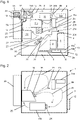
- the cooling device 14 and the flow fan 15 are, as in figure 2 shown, formed and aligned within the housing 2 so that a corresponding flow 25 is formed and specific measurement and / or analysis modules 11, 11a, 11b, 11c are flown accordingly.
- Baffles 20, 20a, 20b are arranged within the housing 2 between the system area 4 and the sample area 3 for guiding the flow 25 in the system area 4.
- the baffles 20, 20a, 20b essentially completely cover the sample area 3 and, in addition to a passage for the optical radiation detected by the optical element 7, have openings 21, 21a, via which the sample area 3 is fluidically connected to the system area 4. Due to the fluidic connection of the system area 4 and the sample area 3 via the openings 21, 21a, these are not hermetically separated from one another.
- the openings 21, 21a have an opening area of approx. 35 cm 2 , the openings 21, 21a being formed at different heights above the bottom 2a of the housing 2.
- FIG. A closure means 22 is arranged in front of the opening 21, by means of which the opening area of the opening 21 can be changed and also completely covered.
- the closure means 22 can be controlled via a control device, not shown in detail, so that the opening area of the opening 21 between the sample area 3 and the system area 4 can be adjusted by the closure means 22 .
- the opening 21 can be covered, for example, so that the sample area 3 is essentially separated from the system area 4 and the sample area can be heated.
- a type of heat trap is formed by the arrangement of the baffles 20, 20a, 20b and the opening 21, 21a in the sample area 3, which on the one hand slows down the rise of a gaseous medium heated in the sample area 3 and at the same time enables a subsequent flow out of the system area and thus a cooled gaseous medium.
- the opening 21 can be released by moving the closure means 22, as a result of which a convective exchange with the system area 4 takes place. Cooling of the sample area 3 can be accelerated by means of a fan 23 arranged in front of the opening 21 in the system area 4, which is designed as a radial fan, in that the heated medium in the sample area 3 is sucked into the system area 4 by means of the fan 23.
- the gaseous medium in the housing 2 flows into the sample area 3 via the opening 21a, which medium originates from the flow 25 of the convective cooling.
- the fan 23 can also conduct a cooled flow from the system area 4 into the sample area 3 .
- the cooling device 14 arranged in the system area 4 not only enables the measurement and/or analysis modules 11, 11a, 11b, 11c arranged in the system area 4 to be cooled, but also allows the sample area 3 to be cooled at the same time, in particular by means of convective cooling or a by the fan 23 forced active cooling.
- the openings 21, 21a thus enable cooling of the sample region 3, in particular also cooling below room temperature, with the thermal conditions to be achieved depending on the cooling device. Furthermore, for example, setting the speed of the fan 23 enables a targeted influencing of the convective cooling in the sample area 3, so that corresponding thermal conditions can be set there.
- the guide elements 20, 20a, 20b are designed as metal sheets, but they can also be made from a different material.
- further guide elements 20c can be arranged in the system area 4, by means of which the flow 25 in the system area 4, in particular between the measurement and/or analysis modules 11, 11a, 11b, 11c, is further influenced and guided.
Landscapes
- Physics & Mathematics (AREA)
- Spectroscopy & Molecular Physics (AREA)
- Health & Medical Sciences (AREA)
- Life Sciences & Earth Sciences (AREA)
- Chemical & Material Sciences (AREA)
- Analytical Chemistry (AREA)
- Biochemistry (AREA)
- General Health & Medical Sciences (AREA)
- General Physics & Mathematics (AREA)
- Immunology (AREA)
- Pathology (AREA)
- Automatic Analysis And Handling Materials Therefor (AREA)
- Sampling And Sample Adjustment (AREA)
Applications Claiming Priority (1)
| Application Number | Priority Date | Filing Date | Title |
|---|---|---|---|
| DE102021112938.9A DE102021112938A1 (de) | 2021-05-19 | 2021-05-19 | Mikroplatten-Lesegerät |
Publications (3)
| Publication Number | Publication Date |
|---|---|
| EP4092404A1 true EP4092404A1 (fr) | 2022-11-23 |
| EP4092404C0 EP4092404C0 (fr) | 2025-01-29 |
| EP4092404B1 EP4092404B1 (fr) | 2025-01-29 |
Family
ID=81585826
Family Applications (1)
| Application Number | Title | Priority Date | Filing Date |
|---|---|---|---|
| EP22171870.3A Active EP4092404B1 (fr) | 2021-05-19 | 2022-05-05 | Lecteur de microdisques |
Country Status (2)
| Country | Link |
|---|---|
| EP (1) | EP4092404B1 (fr) |
| DE (1) | DE102021112938A1 (fr) |
Citations (4)
| Publication number | Priority date | Publication date | Assignee | Title |
|---|---|---|---|---|
| US20040256963A1 (en) * | 2003-01-31 | 2004-12-23 | Affleck Rhett L. | Automated sample analysis system and method |
| WO2013181347A1 (fr) * | 2012-05-31 | 2013-12-05 | Bti Holdings, Inc. | Système multidétection universel pour des microplaques |
| US20160123886A1 (en) * | 2014-10-29 | 2016-05-05 | Lumencor, Inc. | Integrated fluorescence scanning system |
| DE102015214414A1 (de) * | 2015-07-29 | 2017-02-02 | Berthold Technologies Gmbh & Co. Kg | Verfahren und System zur Ermittlung biologischer Eigenschaften von Proben |
Family Cites Families (2)
| Publication number | Priority date | Publication date | Assignee | Title |
|---|---|---|---|---|
| US9114399B2 (en) | 2010-08-31 | 2015-08-25 | Canon U.S. Life Sciences, Inc. | System and method for serial processing of multiple nucleic acid assays |
| DE102020128003A1 (de) | 2020-10-23 | 2020-12-31 | Bmg Labtech Gmbh | Mikroplatten-Lesegerät |
-
2021
- 2021-05-19 DE DE102021112938.9A patent/DE102021112938A1/de active Pending
-
2022
- 2022-05-05 EP EP22171870.3A patent/EP4092404B1/fr active Active
Patent Citations (4)
| Publication number | Priority date | Publication date | Assignee | Title |
|---|---|---|---|---|
| US20040256963A1 (en) * | 2003-01-31 | 2004-12-23 | Affleck Rhett L. | Automated sample analysis system and method |
| WO2013181347A1 (fr) * | 2012-05-31 | 2013-12-05 | Bti Holdings, Inc. | Système multidétection universel pour des microplaques |
| US20160123886A1 (en) * | 2014-10-29 | 2016-05-05 | Lumencor, Inc. | Integrated fluorescence scanning system |
| DE102015214414A1 (de) * | 2015-07-29 | 2017-02-02 | Berthold Technologies Gmbh & Co. Kg | Verfahren und System zur Ermittlung biologischer Eigenschaften von Proben |
Also Published As
| Publication number | Publication date |
|---|---|
| DE102021112938A1 (de) | 2022-11-24 |
| EP4092404C0 (fr) | 2025-01-29 |
| EP4092404B1 (fr) | 2025-01-29 |
Similar Documents
| Publication | Publication Date | Title |
|---|---|---|
| EP1348123B1 (fr) | Procede d'analyse permettant la detection de motifs de repartition spatiale d'oligo-elements, et dispositif servant a mettre en oeuvre le procede | |
| EP1575706B1 (fr) | Chambre climatisee pour microscopes | |
| DE102014102050B4 (de) | Vorrichtung und Verfahren zur Bestimmung der Konzentration zumindest eines Gases in einem Probengasstrom mittels Infrarotabsorptionsspektroskopie | |
| DE112020000560T5 (de) | Flüchtigkeitsaufgelöste chemische Charakterisierung von Schwebstoffen | |
| DE19952293B4 (de) | Röntgenfluoreszenzanalysator | |
| EP3928082B1 (fr) | Procédé et dispositif d'identification de substances volatiles par spectroscopie raman amplifiée par résonateur à pression réduite | |
| DE69510062T2 (de) | Temperaturregelung für im nahen infrarot arbeitenden analysator | |
| EP2145682A1 (fr) | Elément de test destiné à l'analyse d'un analyte contenu dans un échantillon de liquide corporel, système d'analyse et procédé de commande du mouvement d'un liquide contenu dans un canal d'un élément de test | |
| DE102008047415B4 (de) | Mikrotom zum Herstellen von Schnitten eines Objekts | |
| DE2819711C2 (de) | Verfahren und Vorrichtung zur Analyse einer Probe mit Hilfe gepulster Laserstrahlung | |
| EP2418472A1 (fr) | Dispositif d'agencement d'au moins un récipient d'échantillons dans un appareil de mesure optique, appareil de mesure optique doté d'un tel dispositif et utilisation d'un tel appareil de mesure optique | |
| EP4092404B1 (fr) | Lecteur de microdisques | |
| DE102021133081B3 (de) | Mikroplatten-Lesegerät und Verfahren zum Durchführen von optischen Messungen mit einem Mikroplatten-Lesegerät | |
| DE4232371C2 (de) | Analysengerät zur Bestimmung von Gasen oder Flüssigkeiten | |
| DE112020005780T5 (de) | Systeme und verfahren zur abbildung und ablation einer probe | |
| DE4206109C2 (de) | Verfahren und Vorrichtung zur Aufbereitung fester Proben mit Hilfe pyrolytischer Verdampfung für eine Analyse mittels eines Massenspektrometers oder eines Gaschromatographen | |
| DE102011008101A1 (de) | Vorrichtung zum Trennen und Kondensieren einer Mischung | |
| DE69937618T2 (de) | Vorrichtung und Methode zur Messung der optischen Dichte | |
| DE112009002620B4 (de) | Inkubatorvorrichtung und Verfahren | |
| DE10132761B4 (de) | Klimatisierbare Probenkammer und Verfahren zur Klimatisierung der Umgebung von Proben | |
| DE4213051A1 (de) | Verfahren und Anordnung zum Messen der Konzentration eines Nachweisgases in einem ein Störgas enthaltenden Meßgas | |
| EP4664181A2 (fr) | Microscope inverse | |
| CH711376A2 (de) | Verfahren und System zur Ermittlung biologischer Eigenschaften von Proben. | |
| JP2007017350A (ja) | X線分析装置 | |
| WO2025097190A1 (fr) | Analyseur doté d'un dispositif de refroidissement |
Legal Events
| Date | Code | Title | Description |
|---|---|---|---|
| PUAI | Public reference made under article 153(3) epc to a published international application that has entered the european phase |
Free format text: ORIGINAL CODE: 0009012 |
|
| STAA | Information on the status of an ep patent application or granted ep patent |
Free format text: STATUS: THE APPLICATION HAS BEEN PUBLISHED |
|
| AK | Designated contracting states |
Kind code of ref document: A1 Designated state(s): AL AT BE BG CH CY CZ DE DK EE ES FI FR GB GR HR HU IE IS IT LI LT LU LV MC MK MT NL NO PL PT RO RS SE SI SK SM TR |
|
| STAA | Information on the status of an ep patent application or granted ep patent |
Free format text: STATUS: REQUEST FOR EXAMINATION WAS MADE |
|
| 17P | Request for examination filed |
Effective date: 20230330 |
|
| RBV | Designated contracting states (corrected) |
Designated state(s): AL AT BE BG CH CY CZ DE DK EE ES FI FR GB GR HR HU IE IS IT LI LT LU LV MC MK MT NL NO PL PT RO RS SE SI SK SM TR |
|
| STAA | Information on the status of an ep patent application or granted ep patent |
Free format text: STATUS: EXAMINATION IS IN PROGRESS |
|
| 17Q | First examination report despatched |
Effective date: 20240422 |
|
| GRAP | Despatch of communication of intention to grant a patent |
Free format text: ORIGINAL CODE: EPIDOSNIGR1 |
|
| STAA | Information on the status of an ep patent application or granted ep patent |
Free format text: STATUS: GRANT OF PATENT IS INTENDED |
|
| INTG | Intention to grant announced |
Effective date: 20240912 |
|
| GRAS | Grant fee paid |
Free format text: ORIGINAL CODE: EPIDOSNIGR3 |
|
| GRAA | (expected) grant |
Free format text: ORIGINAL CODE: 0009210 |
|
| STAA | Information on the status of an ep patent application or granted ep patent |
Free format text: STATUS: THE PATENT HAS BEEN GRANTED |
|
| AK | Designated contracting states |
Kind code of ref document: B1 Designated state(s): AL AT BE BG CH CY CZ DE DK EE ES FI FR GB GR HR HU IE IS IT LI LT LU LV MC MK MT NL NO PL PT RO RS SE SI SK SM TR |
|
| REG | Reference to a national code |
Ref country code: GB Ref legal event code: FG4D Free format text: NOT ENGLISH |
|
| REG | Reference to a national code |
Ref country code: CH Ref legal event code: EP |
|
| REG | Reference to a national code |
Ref country code: DE Ref legal event code: R096 Ref document number: 502022002747 Country of ref document: DE |
|
| REG | Reference to a national code |
Ref country code: IE Ref legal event code: FG4D Free format text: LANGUAGE OF EP DOCUMENT: GERMAN |
|
| U01 | Request for unitary effect filed |
Effective date: 20250203 |
|
| U07 | Unitary effect registered |
Designated state(s): AT BE BG DE DK EE FI FR IT LT LU LV MT NL PT RO SE SI Effective date: 20250207 |
|
| U20 | Renewal fee for the european patent with unitary effect paid |
Year of fee payment: 4 Effective date: 20250416 |
|
| PG25 | Lapsed in a contracting state [announced via postgrant information from national office to epo] |
Ref country code: RS Free format text: LAPSE BECAUSE OF FAILURE TO SUBMIT A TRANSLATION OF THE DESCRIPTION OR TO PAY THE FEE WITHIN THE PRESCRIBED TIME-LIMIT Effective date: 20250429 |
|
| PG25 | Lapsed in a contracting state [announced via postgrant information from national office to epo] |
Ref country code: PL Free format text: LAPSE BECAUSE OF FAILURE TO SUBMIT A TRANSLATION OF THE DESCRIPTION OR TO PAY THE FEE WITHIN THE PRESCRIBED TIME-LIMIT Effective date: 20250129 |
|
| PG25 | Lapsed in a contracting state [announced via postgrant information from national office to epo] |
Ref country code: ES Free format text: LAPSE BECAUSE OF FAILURE TO SUBMIT A TRANSLATION OF THE DESCRIPTION OR TO PAY THE FEE WITHIN THE PRESCRIBED TIME-LIMIT Effective date: 20250129 |
|
| PG25 | Lapsed in a contracting state [announced via postgrant information from national office to epo] |
Ref country code: NO Free format text: LAPSE BECAUSE OF FAILURE TO SUBMIT A TRANSLATION OF THE DESCRIPTION OR TO PAY THE FEE WITHIN THE PRESCRIBED TIME-LIMIT Effective date: 20250429 Ref country code: IS Free format text: LAPSE BECAUSE OF FAILURE TO SUBMIT A TRANSLATION OF THE DESCRIPTION OR TO PAY THE FEE WITHIN THE PRESCRIBED TIME-LIMIT Effective date: 20250529 |
|
| PG25 | Lapsed in a contracting state [announced via postgrant information from national office to epo] |
Ref country code: HR Free format text: LAPSE BECAUSE OF FAILURE TO SUBMIT A TRANSLATION OF THE DESCRIPTION OR TO PAY THE FEE WITHIN THE PRESCRIBED TIME-LIMIT Effective date: 20250129 |
|
| PG25 | Lapsed in a contracting state [announced via postgrant information from national office to epo] |
Ref country code: GR Free format text: LAPSE BECAUSE OF FAILURE TO SUBMIT A TRANSLATION OF THE DESCRIPTION OR TO PAY THE FEE WITHIN THE PRESCRIBED TIME-LIMIT Effective date: 20250430 |
|
| PG25 | Lapsed in a contracting state [announced via postgrant information from national office to epo] |
Ref country code: SM Free format text: LAPSE BECAUSE OF FAILURE TO SUBMIT A TRANSLATION OF THE DESCRIPTION OR TO PAY THE FEE WITHIN THE PRESCRIBED TIME-LIMIT Effective date: 20250129 |
|
| PG25 | Lapsed in a contracting state [announced via postgrant information from national office to epo] |
Ref country code: CZ Free format text: LAPSE BECAUSE OF FAILURE TO SUBMIT A TRANSLATION OF THE DESCRIPTION OR TO PAY THE FEE WITHIN THE PRESCRIBED TIME-LIMIT Effective date: 20250129 |
|
| PG25 | Lapsed in a contracting state [announced via postgrant information from national office to epo] |
Ref country code: SK Free format text: LAPSE BECAUSE OF FAILURE TO SUBMIT A TRANSLATION OF THE DESCRIPTION OR TO PAY THE FEE WITHIN THE PRESCRIBED TIME-LIMIT Effective date: 20250129 |
|
| PLBE | No opposition filed within time limit |
Free format text: ORIGINAL CODE: 0009261 |
|
| STAA | Information on the status of an ep patent application or granted ep patent |
Free format text: STATUS: NO OPPOSITION FILED WITHIN TIME LIMIT |
|
| REG | Reference to a national code |
Ref country code: CH Ref legal event code: L10 Free format text: ST27 STATUS EVENT CODE: U-0-0-L10-L00 (AS PROVIDED BY THE NATIONAL OFFICE) Effective date: 20251210 |
|
| REG | Reference to a national code |
Ref country code: CH Ref legal event code: H13 Free format text: ST27 STATUS EVENT CODE: U-0-0-H10-H13 (AS PROVIDED BY THE NATIONAL OFFICE) Effective date: 20251223 |
|
| 26N | No opposition filed |
Effective date: 20251030 |
|
| PG25 | Lapsed in a contracting state [announced via postgrant information from national office to epo] |
Ref country code: CH Free format text: LAPSE BECAUSE OF NON-PAYMENT OF DUE FEES Effective date: 20250531 |
|
| PG25 | Lapsed in a contracting state [announced via postgrant information from national office to epo] |
Ref country code: MC Free format text: LAPSE BECAUSE OF FAILURE TO SUBMIT A TRANSLATION OF THE DESCRIPTION OR TO PAY THE FEE WITHIN THE PRESCRIBED TIME-LIMIT Effective date: 20250129 |
|
| PG25 | Lapsed in a contracting state [announced via postgrant information from national office to epo] |
Ref country code: IE Free format text: LAPSE BECAUSE OF NON-PAYMENT OF DUE FEES Effective date: 20250505 |