EP4092580A1 - Verfahren zur stabilisierung von neuralen signalen - Google Patents
Verfahren zur stabilisierung von neuralen signalen Download PDFInfo
- Publication number
- EP4092580A1 EP4092580A1 EP22173023.7A EP22173023A EP4092580A1 EP 4092580 A1 EP4092580 A1 EP 4092580A1 EP 22173023 A EP22173023 A EP 22173023A EP 4092580 A1 EP4092580 A1 EP 4092580A1
- Authority
- EP
- European Patent Office
- Prior art keywords
- day
- model
- neural
- signals
- translation
- Prior art date
- Legal status (The legal status is an assumption and is not a legal conclusion. Google has not performed a legal analysis and makes no representation as to the accuracy of the status listed.)
- Pending
Links
Images





Classifications
-
- G—PHYSICS
- G06—COMPUTING OR CALCULATING; COUNTING
- G06N—COMPUTING ARRANGEMENTS BASED ON SPECIFIC COMPUTATIONAL MODELS
- G06N3/00—Computing arrangements based on biological models
- G06N3/02—Neural networks
- G06N3/08—Learning methods
- G06N3/088—Non-supervised learning, e.g. competitive learning
-
- G—PHYSICS
- G06—COMPUTING OR CALCULATING; COUNTING
- G06N—COMPUTING ARRANGEMENTS BASED ON SPECIFIC COMPUTATIONAL MODELS
- G06N3/00—Computing arrangements based on biological models
- G06N3/02—Neural networks
- G06N3/08—Learning methods
-
- A—HUMAN NECESSITIES
- A61—MEDICAL OR VETERINARY SCIENCE; HYGIENE
- A61B—DIAGNOSIS; SURGERY; IDENTIFICATION
- A61B5/00—Measuring for diagnostic purposes; Identification of persons
- A61B5/24—Detecting, measuring or recording bioelectric or biomagnetic signals of the body or parts thereof
- A61B5/316—Modalities, i.e. specific diagnostic methods
- A61B5/369—Electroencephalography [EEG]
- A61B5/37—Intracranial electroencephalography [IC-EEG], e.g. electrocorticography [ECoG]
-
- A—HUMAN NECESSITIES
- A61—MEDICAL OR VETERINARY SCIENCE; HYGIENE
- A61B—DIAGNOSIS; SURGERY; IDENTIFICATION
- A61B5/00—Measuring for diagnostic purposes; Identification of persons
- A61B5/72—Signal processing specially adapted for physiological signals or for diagnostic purposes
- A61B5/7235—Details of waveform analysis
- A61B5/7264—Classification of physiological signals or data, e.g. using neural networks, statistical classifiers, expert systems or fuzzy systems
- A61B5/7267—Classification of physiological signals or data, e.g. using neural networks, statistical classifiers, expert systems or fuzzy systems involving training the classification device
-
- G—PHYSICS
- G06—COMPUTING OR CALCULATING; COUNTING
- G06F—ELECTRIC DIGITAL DATA PROCESSING
- G06F3/00—Input arrangements for transferring data to be processed into a form capable of being handled by the computer; Output arrangements for transferring data from processing unit to output unit, e.g. interface arrangements
- G06F3/01—Input arrangements or combined input and output arrangements for interaction between user and computer
- G06F3/011—Arrangements for interaction with the human body, e.g. for user immersion in virtual reality
- G06F3/015—Input arrangements based on nervous system activity detection, e.g. brain waves [EEG] detection, electromyograms [EMG] detection, electrodermal response detection
-
- G—PHYSICS
- G06—COMPUTING OR CALCULATING; COUNTING
- G06N—COMPUTING ARRANGEMENTS BASED ON SPECIFIC COMPUTATIONAL MODELS
- G06N3/00—Computing arrangements based on biological models
- G06N3/02—Neural networks
- G06N3/04—Architecture, e.g. interconnection topology
- G06N3/045—Combinations of networks
-
- G—PHYSICS
- G06—COMPUTING OR CALCULATING; COUNTING
- G06N—COMPUTING ARRANGEMENTS BASED ON SPECIFIC COMPUTATIONAL MODELS
- G06N3/00—Computing arrangements based on biological models
- G06N3/02—Neural networks
- G06N3/04—Architecture, e.g. interconnection topology
- G06N3/045—Combinations of networks
- G06N3/0455—Auto-encoder networks; Encoder-decoder networks
-
- G—PHYSICS
- G06—COMPUTING OR CALCULATING; COUNTING
- G06N—COMPUTING ARRANGEMENTS BASED ON SPECIFIC COMPUTATIONAL MODELS
- G06N3/00—Computing arrangements based on biological models
- G06N3/02—Neural networks
- G06N3/04—Architecture, e.g. interconnection topology
- G06N3/0464—Convolutional networks [CNN, ConvNet]
-
- G—PHYSICS
- G06—COMPUTING OR CALCULATING; COUNTING
- G06N—COMPUTING ARRANGEMENTS BASED ON SPECIFIC COMPUTATIONAL MODELS
- G06N3/00—Computing arrangements based on biological models
- G06N3/02—Neural networks
- G06N3/04—Architecture, e.g. interconnection topology
- G06N3/047—Probabilistic or stochastic networks
-
- G—PHYSICS
- G06—COMPUTING OR CALCULATING; COUNTING
- G06N—COMPUTING ARRANGEMENTS BASED ON SPECIFIC COMPUTATIONAL MODELS
- G06N3/00—Computing arrangements based on biological models
- G06N3/02—Neural networks
- G06N3/04—Architecture, e.g. interconnection topology
- G06N3/0475—Generative networks
-
- G—PHYSICS
- G06—COMPUTING OR CALCULATING; COUNTING
- G06N—COMPUTING ARRANGEMENTS BASED ON SPECIFIC COMPUTATIONAL MODELS
- G06N3/00—Computing arrangements based on biological models
- G06N3/02—Neural networks
- G06N3/08—Learning methods
- G06N3/082—Learning methods modifying the architecture, e.g. adding, deleting or silencing nodes or connections
-
- G—PHYSICS
- G06—COMPUTING OR CALCULATING; COUNTING
- G06N—COMPUTING ARRANGEMENTS BASED ON SPECIFIC COMPUTATIONAL MODELS
- G06N3/00—Computing arrangements based on biological models
- G06N3/02—Neural networks
- G06N3/08—Learning methods
- G06N3/0895—Weakly supervised learning, e.g. semi-supervised or self-supervised learning
-
- G—PHYSICS
- G06—COMPUTING OR CALCULATING; COUNTING
- G06N—COMPUTING ARRANGEMENTS BASED ON SPECIFIC COMPUTATIONAL MODELS
- G06N3/00—Computing arrangements based on biological models
- G06N3/02—Neural networks
- G06N3/08—Learning methods
- G06N3/094—Adversarial learning
Definitions
- a brain computer interface comprises a neural interface that receives neural signals from brain neurons or peripheral nerves.
- the BCI translates the neural signals into stimulus identities or cognitive/behavioral intents that are mapped to a desired function or neurological muscular command.
- a BCI may be used in conjunction with a prosthetic device to greatly improve the patient experience and operability of the prosthetic device.
- neural signals measured at the brain or periphery are configured to control the prosthetic by mapping them to the user's desired motor intent (e.g. how they want to move their hand).
- a BCI may also be configured to move a computer cursor or robotic arm for patient with tetraplegia.
- Brain implanted BCIs typically use one of two interface types, an electrocorticography (ECoG) interface or a Multi-electrode array (MEA) interface.
- ECIs electrocorticography
- MEAs Multi-electrode array
- PSTHs peristimulus time histograms
- ECoG arrays do not measure spikes from individual neurons, but instead measure correlated neural activity from large populations of neurons in local field potentials (LFPs).
- neural signals e.g. spikes or LFPs
- the observed spikes measured with MEAs can change for many reasons including: electrode malfunction or movement, and local neuron death or adaptation. These changes in the observed spikes may lead to disruption of the observed stimulus responses including the entire loss of an electrode channel or more subtle differences in the stimulus-specific spike rates.
- the LFPs measured with ECoG can experience changes to their power spectrum.
- patients typically need to make frequent visits to a clinician to have the BCI recalibrated for these changes in measured signal. This process of manual recalibration is a problem with chronically implanted neural interfaces and greatly limits the potential of BCIs.
- BCIs function optimally on the day of calibration when the neural signals are clean and most similar to the dataset used to train the BCI.
- each subsequent day of use may increase the level of degradation of the neural signals and may result in the overall decline in the functionality of the BCI.
- the neural signals may become distorted to a point where the BCI is unable to process the incoming neural signals at all.
- the substantial benefits of the BCI implants may be negated by the recalibration schedule required to keep the devices working properly. Further, the calibration process may only be made with knowledge of the BCI interface type and BCI application.
- the present disclosure provides a method for translating disrupted neural signals comprising: receiving, at a brain-computer interface (BCI), a first set of neural signals and a second set of neural signals, wherein the first set of neural signals comprises day 0 data and wherein the second set of neural signals comprises day i data; transmitting, to a computing device comprising at least one processor coupled to at least one memory unit, the first set of neural signals and the second set of neural signals and storing the signals in a first datastore and a second datastore of the computing device; training, by the computing device, a plurality of neural translation models in an adversarial networks for neural interfaces (ANNI) method, wherein the ANNI method trains a plurality of translation models, and wherein the plurality of translation models comprise a first autoencoder model, a second autoencoder model, a disrupted recovery model, an artificial disruption model, a first discriminator model, a second discriminator model, shared latent space model, a shared signal space model, and a penalty drift
- the present disclosure provides a method for translating disrupted neural signals comprising: receiving, at a brain-computer interface (BCI), a first set of neural signals and a second set of neural signals, wherein the first set of neural signals comprises day 0 data and wherein the second set of neural signals comprises day i data; transmitting, to a computing device comprising at least one processor coupled to at least one memory unit, the first set of neural signals and the second set of neural signals and storing the signals in a first datastore and a second datastore of the computing device; training, by the computing device, a plurality of neural translation models in an adversarial networks for neural interfaces (ANNI) method, wherein the ANNI method trains a plurality of translation models, and wherein the plurality of translation models comprise a first autoencoder model, a second autoencoder model, a disrupted recovery model, an artificial disruption model, a first discriminator model, a second discriminator model, shared latent space model, a shared signal space model, and a penalty
- related systems include but are not limited to circuitry and/or programming for effecting herein-referenced method aspects; the circuitry and/or programming can be virtually any combination of hardware, software, and/or firmware configured to effect the herein-referenced method aspects depending upon the design choices of the system designer.
- circuitry and/or programming can be virtually any combination of hardware, software, and/or firmware configured to effect the herein-referenced method aspects depending upon the design choices of the system designer.
- the present disclosure is directed to an unsupervised and automated method for stabilizing neural signals received by a brain-computer interface (BCI).
- BCI brain-computer interface
- the method may be used on a variety of signal types and therefore is agnostic to the type of interface, (e.g. electrocorticography (ECoG) or Multi-electrode arrays (MEAs)), and the type of signal degradation.
- EoG electrocorticography
- MEAs Multi-electrode arrays
- the method employs a neural network to train a plurality of models based on a clean Dataset A and a disrupted Dataset B.
- the disrupted Dataset B refers to a representative set of signals captured at any time point beyond the initial point of BCI calibration/training.
- the trained neural network model is configured to translate the signals from the disrupted Dataset B to their analogous exemplars from the clean Dataset A.
- the training method is based on a cycle consistent generative adversarial network (GAN).
- GAN cycle consistent generative adversarial network
- This architecture is specifically implemented for a network analogous to the unsupervised image to image translation model (UNIT) that uses unpaired input samples.
- the method for translating and stabilizing neural signals may be applied to an existing BCI as a modular application or integrated into a new BCI. Due to the variability of signal disruption factors, a plurality of models are trained providing multiple opportunities to develop a model that produces a high translation accuracy for the observed signal disruption. Once the plurality of models are trained, the accuracy of each model is predicted using a set of internal metrics without supervision.
- the model with the highest predicted accuracy is selected and applied to translate new signals measured at the neural interface at future time points.
- the incoming neural signals may experience further degradation and require the models to be retrained and reselected each day.
- the selected model from the previous day may be used as one of the plurality of models that is trained for the subsequent day.
- FIG. 1 illustrates a method 1 for training a neural signal translation model in adversarial networks for neural interfaces (ANNI) method, executed by a computing device, in accordance with at least one aspect of the present disclosure.
- the method 1 may be executed by a computing device internal or external to the BCI, as described hereinbelow.
- a BCI receives 2 reference data for a training algorithm including day 0 and day i data.
- day 0 data is a reference dataset of clean neural signals
- day i data is a reference dataset of disrupted neural signals, where i is a positive integer greater than 1.
- the ANNI method concurrently trains a clean translation model on day 0 and a disruption translation model on day i data to optimize the accuracy of the underlying model.
- the day 0 data is recorded the same day that the BCI is calibrated or recalibrated, and is used as the target translation data.
- the day 0 signals are considered to be the most accurate representation of the behavioral intent and are stored in Dataset A as the clean day 0 dataset.
- the subsequently measured neural signals, recorded on day i are stored as the disrupted signal dataset, Dataset B.
- the ANNI method trains 4 a plurality of models to translate or recover the signals in of Dataset B back to their original state represented in Dataset A.
- the accuracy of trained models may be determined by any number of internal metrics that are intrinsic to Dataset A and/or a trained neural decoder present in the BCI.
- an internal metric may compare the recovered signal distributions (X BA in FIG. 2 ) according to the mean and variance of the signals in Dataset A, and selecting the point in training with the closest match. If a neural decoder is present and accessible, one can also use the distribution of expected decoded values (e.g. decoder entropy).
- the ANNI method determines 6 that the trained model meets a predetermined accuracy threshold, where the model is deemed to be maximally accurate based on decoder entropy, or once a training model has achieved an optimal value for the selected internal metric in a predetermined amount of time.
- Each internal metric value of each completely trained model is compared by the computing device to determine the most accurate or best performing model for that day.
- the computing device selects 8 the translation model based on the model with the highest decoder entropy or internal metric value.
- FIG. 2 illustrates an individual neural network components used by the ANNI method 150 for training a neural signal translation model, in accordance with at least one aspect of the present disclosure.
- the training process employs a variation of a GAN architecture 150, herein referred as ANNI, e.g., adversarial networks for neural interfaces.
- ANNI e.g., adversarial networks for neural interfaces.
- a plurality of neural brain signal model segments are trained in the ANNI method 150 to translate incoming disrupted neural signals to recovered neural signals.
- the ANNI method 150 comprises a generator 100 and a discriminator portion 130 configured to receive signals from the generator 100 and process the received signals in accordance with methods described herein.
- the generator 100 comprises two encoders 110, 112, a shared latent space 126, and two decoders 114, 116.
- the output of the generator 100 is dependent on the translation path, where different translation paths correspond to different model layers. Depending on the signal translation path, different model layers may be applied to the signal in the encoding, mapping, or decoding phase.
- the generator outputs x AA signals 118 and x BB signals 120 from the autoencoder pathways, x AB signals 122 from the artificial disruption pathways, and x BA signals 120 from the recovery pathways.
- the encoders 110, 112 and decoders 114, 116 may use a plurality of different neural signal simulation models that correspond to MEA or ECoG interfaces and different biological or physical signal disruptions.
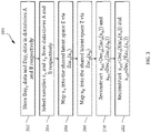
- FIG. 3 illustrates one aspect of a signal generation process 200 for the ANNI method.
- input signals x A and x B correspond to signals day 0 and day i respectively and are store in datastores A and B, at 202.
- the signals are sampled 204 from each datastore and are mapped 206, 208 into the shared latent space corresponding to a class-dependent transformation.
- the signals are reconstructed by decoders Dec A 210 or Dec B 212 and are passed to the discriminator portion of the ANNI architecture.
- FIG. 4 illustrates the recovery pathway for a disrupted day i signal.
- Signal x B 108 is received from the disrupted signal datastore B, encoded by Enc B 112, and mapped into the shared latent space z 126.
- Autoencoder signal x A 106 is also mapped to the clean domain of shared latent space z 126.
- Signals x A 106 and x B 108 are reconstructed by Dec A 114, and input singal x B 108 is outputted as a recovered signal x BA 120.
- FIG. 5 illustrates the artificial disruption pathway for a clean day 0 signal.
- Signal x A 106 is received from the clean signal datastore A, encoded by Enc A 110, and mapped to the disrupted domain of shared latent space z 126.
- Autoencoder signal x B 108 is also mapped to the clean domain of shared latent space z 126.
- Signals x A 106 and x B 108 are reconstructed by Dec B 116, and input singal x A 106 is outputted as an artificially disrupted signal x AB 122.
- the same encoding and decoding process is performed with autoencoder signals x AA and x BB , where the encoding and decoding is designed produce original signals x A and x B .
- the neural network topology of the encoders and decoders are feed-forward, rectified linear unit (ReLU) networks, with dropout between layers. Neither activation functions nor dropout are applied in the final layer of the encoder in order to maintain a maximally expressive latent space. Additionally, the dropout signal simulation is not applied before the final layer of the decoder in order to enable the greatest fidelity in reconstructed signals.
- the network topologies are fully-connected for spiking interfaces, when there are no assumptions of spatial correlation in signal space. Convolutional networks can be used for ECoG arrays since spatial correlation in those signal spaces may exist (particularly for ⁇ EC ⁇ G where adjacent electrodes in the grid are separated by small distances).
- the discriminator is trained to classify incoming signals as "real" or "fake", where real corresponds to having come from the original Datasets A or B, and "fake” corresponds to having been an artificially disrupted or a recovered signal.
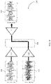
- FIG. 6 illustrates the discriminator portion 130 of the ANNI method, where the signals x AA 118, x BA 120, x AB 122, and x BB 124, are received from the generator.
- Discriminator Disc A 132 receives signals x AA 118 and x BA 120 corresponding to the clean domain
- discriminator Discs 134 receives signals x AB 122 and x BB 124 corresponding to the disrupted signal domain.
- a signal is sampled from a datastore and generated according to a translation model to approximate the sampled signals from the datastore.
- the discriminator attempts to accurately distinguish a sampled signal "real" from a generated signal "fake”.
- Disc A 132 determines the probability that signals 118 and 120 are a real or fake clean neural signal
- Disc B 134 determines the probability that signals 122 and 122 are a real or fake disrupted neural signal.
- the discriminator architectures are feed-forward rectified linear unit (ReLU) binary classification networks with a sigmoid applied to the output layer. Each discriminator operates in the signal space and outputs a prediction value between 0 and 1, where Disc A (x n ) > 0.5 is interpreted as a "real" signal, or having come from Datastore A, and Disc A (x n ) ⁇ 0.5 is interpreted as a "fake” signal, or having come through the recovery pathway Dec A (Enc B (x B )).
- ReLU rectified linear unit
- Disc B (x n ) > 0.5 is interpreted as a "real" signal, or having come from datastore B
- Disc B ( Xn ) ⁇ 0.5 is interpreted as a "fake” signal, or having come through the artificial disruption pathway Dec B (Enc A (x A )).
- the networks in the training model are updated according the discriminator results.
- the first step in updating the training model weights is to update the discriminator models to more accurately distinguish between incoming signals and generated signals.
- the discriminator output is evaluated according to a binary cross-entropy (BCE) training objective and produces a discriminator loss function.
- BCE binary cross-entropy
- These signals may be considered as part of the "generative" processes since the resulting signal is only statistically related to signals collected from the BCI, and has no counterpart in either dataset.
- the loss L Gen (Gen BA ) may be used to update the networks Enc B and Dec A
- the loss L Gen (Gen BA ) may be used to update the networks Enc A and Dec B .
- the purpose of interpreting the recovery (and artificial disruption) pathway as a generator, and guiding that generator using a discriminator, is to obtain a non-disrupted representation of each incoming neural recording that is statistically similar to the non-disrupted dataset. This does not solve the class matching problem, which is addressed though Cycle Consistency and an ad-hoc drift penalty.
- Cycle consistency describes the ability to accurately reconstruct a single incoming signal by first transferring it across one domain, and then transferring the result across the other domain.
- Cycle consistency describes the ability to accurately reconstruct a single incoming signal by first transferring it across one domain, and then transferring the result across the other domain.
- cycle consistency provides the opportunity to align the latent representation of non-disrupted signals with disrupted signals from the same class. Cycle consistency itself does not guarantee class alignment alone therefore a recovery drift penalty L drift is used to mitigate the undesirable class-swapping problem.
- Class swapping refers to the situation where the neural network will learn to accurately translate the set of signals in X B ⁇ X BA , however the class identities are translated in a completely mismatched way. For example, a neural signal from a first class may be translated to a second class and vice versa. While this solution accurately reproduces the distribution of signals present in the original Dataset A, it leads to a completely dysfunctional BCI. One where, for example, the disrupted neural signal for moving one's index finger would be translated (and subsequently incorrectly decoded) as a clean signal indicating movement of the thumb.
- the autoencoder training models are updated according to how accurately the original signal x A and X B xB are reconstructed. Learned weights for the corresponding encoder and decoder are updated to optimize the reconstruction losses for each autoencoder model.
- a single epoch is achieved when the learned weights have been updated to accommodate all training objectives described above on all of the available data in Datasets A and B.
- the training proceeds through multiple epochs until the internal metric on the recovered set of signals reaches a predetermined value or relative minimum/maximum over a predetermined number of epochs.
- the translation model is considered to be trained.
- a typical translation model meets this threshold in 100 to 1000 epochs.
- the internal metric can be any measure which can be computed based on parameters or properties of the data or the neural network as long as it does not require ground-truth class labeling of the incoming disrupted signals.
- it can be the difference between signal distributions of the clean x A and the recovered/translated set X BA , or the entropy in decoded class values of the translated set X BA .
- Whatever metric is used should retain a high correlation with the translated signal accuracy in order to be effective.
- the strong correlation between high decoder entropy (for example) and high decoder, at the model level enables both the selection of top performing models from among fully trained models, as well as the retrospective identification of optimal stopping points during training of single models to freeze neural network weights.
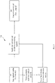
- FIG. 7 illustrates an aspect of a translation model 500 where, a BCI receives 502 disrupted neural signals for day i .
- the day i signals are stored in Dataset B and the ANNI method trains 504 multiple new translation model based on the day i disrupted signals. At this instance, a new translation model may not yet be selected for day i + 1 .
- the ANNI method selects 506 the day i + 1 translation model, and the BCI applies 508 the selected translation model, trained on day i signals, for incoming signals on day i + 1 .
- the BCI outputs 510 the recovered signals for the incoming signals received on day i + 1 .
- the incoming day i + 1 disrupted signals may comprises a partial dataset and the computing device may execute the ANNI method for an intraday translation mode.
- the intraday translation model Once the intraday translation model is trained, the translation model trained on dayi signals is discontinued and immediately replaced with the intraday translation model.
- the intraday translation model is updated at the BCI and incoming neural signals may be recovered in real-time.
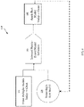
- FIG. 8 illustrates a process 600 where the selected day i translation model is evaluated 604 against the trained 602 models for day i + 1 .
- the internal metric value for the day i translation model is calculated and compared 606 with the values from the current day's batch of trained models. In this way, a single previously-trained 604 model may outperform all current trained 602 models and continue to be selected and applied 608 as the best performing model indefinitely.
- the accuracy of the ANNI method was validated by simulating neural signals from both MEA and ECoG interfaces. In the simulated validation process, the decoder accuracy was observed at over 90 % with all datasets with as much as 13 of 32 channels dropped.
- the MEA simulation model mimics the key components of neural responses recorded from an MEA interface. The model simulates a set of neurons with diverse stimulus responses making up a plurality of classes, where the class corresponds to the true stimulus identity. First, a response of a single neuron is determined by its response probability to a given stimulus, where the response probability is determined by heterogeneous Gaussian tuning curves (GTC).
- GTC heterogeneous Gaussian tuning curves
- the mean and standard deviation (SD) values of the GTCs may be randomly selected within the stimulus range (for mean) or half the stimulus range (for SD).
- the GTCs then generate response probabilities for each neuron from stimuli values defined in time (400 ms with 1 ms sample rate).
- the stimuli in models may be static in time at 1 of 20 different values evenly distributed across the stimulus range. This process generates temporally constant response probabilities.
- response probabilities may be used to generate spikes using a Poisson distribution to simulate noise in spike generation.
- the spikes counts may be binned (100 ms bins), generating 32x4 bin PSTHs (number of channels x number of time bins).
- a second additive noise source may be added to the PSTHs.
- the second additive noise has a SD of 10% of the PSTH mean and all resulting PSTH values below zero are rectified at zero. This process generated 5000 PSTH trials encoding 20 different stimulus classes.
- the MEA disruption simulation models simulate signal degradation based on channel drop-out (drop) or neuron drop-in (swap) disruption models.
- each degradation step may be defined according to the loss of an entire electrode channel.
- Channel drop-out may be simulated by zeroing out all time bins in the PSTH for that particular channel in all samples.
- the channel drop-out loss is cumulative across the multiple degradation steps such that, half of the channels may contain only zeros.
- a degradation step in the drop-in model may be defined according to a change in the stimulus response at an existing channel in the set.
- the stimulus response change may be modeled as a 10% positive or negative shift in the GTC mean (relative to the entire stimulus range) and an increase or decrease in the GTC SD of two times the original SD. Both models mimic common disruptions types observed in MEA sample recordings.
- the ECoG interface model simulates the LFP neural signals as they are observed at the electrodes rather than the underlying activity of neurons.
- forward models of observed activity at the ECoG sensor derived from the underlying neuron populations will be specific to the neural subsystem being measured (e.g. somatosensory vs visual cortex) as well as the type and density of neural array.
- the model sidesteps the implementation of more complex physical models required for simulating neuronal activity and point spread functions to approximate specific population responses while still replicating the fundamental signal qualities of ECoG reported in the literature (e.g. the frequency spectra, amplitude and noise characteristics).
- the model assumes that because ECoG samples are from a large cortical territory, the responses will have spatial heterogeneity.
- the model further assumes that changes in the observed ECoG signal that are relevant for decoding, typically manifest themselves as changes in lower frequency oscillations when averaged over multiple samples.
- the LFP neural signals may be simulated on an 8x8 ⁇ ECoG array where a given stimulus or class may be instantiated with a series of signal inputs. Each signal input may require selecting a channel, frequency, phase, time (within the 1s signal window), or amplitude of a sinusoidal input. Finally, the spatial distance between electrodes in the array may be simulated with a unit grid (1mm spacing) and scaling the modulating input strength as a function of the distance from the center locus of the modulating input. Each modulating input may be added to the 1/F 2 noise at the appropriate channels to produce a spatiotemporal pattern of activity that serves as the starting stimulus class template. Any of these parameters can be manipulated to investigate a different aspect of the model (i.e. array size, frequency of signal inputs etc.).
- one of the primary sources of disruption for ECoG are changes in electrode impedance. These disruptions may be particularly egregious in the first 75 days after implant and may lead to dramatic changes in the variance and spectral power of signals.
- the disruption models use a linear model fit to simulate the degree the degree of changes in each spectral band of the signal over the first 100 days. The length of time since implant is used in the linear model to simulate the change in spectral power over time.
- the changes in the expected signals may then be computed by applying a discrete Fourier transform to each time-domain signal (e.g for each electrode channel and sample), applying a transform function to the signals in Fourier space with the appropriate frequency band coefficients from, and then using an inverse Fourier transform to restore the signals to the time domain.
- the interface may stabilize and the day-to-day or week-to-week changes in signal strength may be confined to a narrower operating range.
- the model may simulates this operating range as +/- 20% of the stable signal strength beyond day 100. These fluctuations may be randomly generated according to a Gaussian distribution centered at 0% signal change at each time step within the allowable bounds.
- Cortical adaptation refers to the change in the neural response itself, as the brain learns to more efficiently utilize the interface.
- the use of ECoG in chronic recordings and BCIs is limited currently and has restricted the study of adaptation to only a few studies. Those studies suggest that cortical adaptation manifests primarily as an increase in the amplitude of these signals over time.
- the simulated disruption model allows the signals to adapt continuously over the simulated lifetime of the implant in the following way. At each time point in the simulation (10 day steps), the model may allow 20% of the modulatory input signals to adapt, selected at random. Each time a signal adapts it can increase or decrease its amplitude by 10-20% prior to accounting for the impedance change.
- the reason for including a long-term depression (signal decrease) mechanism in our simulations was to prevent signal saturation over the longer simulation times (e.g. 360 days).
- the model may adapt signals at each time point (every 10 days for a total of 36) in the simulation and can be adapted multiple times over the time steps.
- the absolute magnitude of possible decrease or increase in a signal may be capped at 70 - 150% of its starting amplitude over the lifetime of the simulation. This results in a set of signals that continuously change their absolute and relative magnitude to each other over the lifetime of the simulation.
- the disclosed aspect allows an implanted BCI to be trained immediately on day 0 datasets with high decoder accuracy.
- FIG. 9 illustrates one aspect of a neural signal stabilization system 700 comprising a wearable physiological signal amplifier system that records 32 channels of high-fidelity neural signals with water based electrodes 708, in accordance with at least one aspect of the present disclosure.
- the neural signal stabilization system 700 includes a BCI 702 with onboard 3D accelerometer and trigger channel, a configuration cap configured for 32-Channels, a head-cap 704 with 32 grommets 706 to receive the water based electrodes 708, water based electrodes 708, and ANNI method 710 that runs off a general purpose computer 712.
- the neural signal stabilization system 700 is configured to neural signals for a BCI.
- the neural signal stabilization system 700 can record many different signal types.
- the electrode configuration or signal type may be quickly changed by swapping out the configuration cap.
- the neural signal stabilization system 700 can telemeter 714 data back to the general purpose computer 712 running software 710 for real-time display 716 and analysis of the signals 718, or record it locally in a memory of the base unit 702 for later download to the computer 710.
- the neural signal stabilization system 700 can switch between WiFi mode, logger mode, or hybrid mode to suit a particular application protocol.
- the neural signal stabilization system is battery operated, rechargeable, and its compact size, integrated WiFi connectivity and flexibility are combined in a mobile physiologic measurement device.
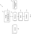
- FIG. 10 illustrates an architectural or component view of a computing system 800 that may be employed to implement the ANNI method for training and selecting a neural signal translation model described in connection with FIGS. 1-8 , in accordance with at least one aspect of the present disclosure.
- the base unit 802 and/or the general purpose computer 712 may comprise the computing system 800 or portions of the computing system 800 to implement the ANNI method in accordance with the present disclosure.
- the computing system 800 may comprise one or more of the GPU processor 802 or the FPGA described previously.
- the computing system 800 comprises one or more processors 802 (e.g., microprocessor, microcontroller) coupled to various sensors 804 (e.g., neural electrodes) and at least one output feedback component 808 via a suitable circuit 806.
- the output feedback component 808 may provide user intended response classification information to the BCI via a suitable circuit 806 such as a device driver 806.
- the one or more processors 802 may be any one of a number of single or multi-core processors known in the art.
- one or more storage devices 810 comprising operating logic 812 for operation is coupled to the one or more processors 802.
- the one or more storage devices 810 may include any suitable device such as a hard drive, random access memory (RAM), read only memory (ROM), or universal serial bus (USB) connected flash drives.
- the one or more storage device 810 may comprise volatile and non-volatile storage media configured to store persistent and temporal copies of the operating logic 812.
- the communication interface 814 may also be coupled to the one or more processors 802.
- one or more processors 802 may be packaged together with the operating logic 812 to, for example, form a System in Package (SiP) or a System on Chip (SoC).
- SiP System in Package
- SoC System on Chip
- one or more processors 802 may be integrated on the same die with the operating logic 812.
- the operating logic 812 may be implemented in instructions supported by the instruction set architecture (ISA) of one or more processors 802, or in higher level languages that are compiled into the supported ISA.
- the operating logic 812 may comprise one or more logic units or modules.
- the operating logic 812 is implemented in an object oriented manner.
- the operating logic 812 also can be configured to be executed in a multi-tasking and/or multi-thread manner.
- the operating logic 812 may be implemented in suitable hardware such as a gate array.
- the communication interface 814 may be configured to facilitate communication between a peripheral device and the computing system 800. The communication may include transmission of the collected neural signals, or brain waves to a hosting computer, and transmission of data associated therewith from the hosting computer to a peripheral device.
- the communication interface 814 may be a wired or a wireless communication interface.
- a wired communication interface may include, but is not limited to, a USB interface.
- An example of a wireless communication interface may include, but is not limited to, a Bluetooth interface, WiFi, among others.
- electrical circuitry includes, but is not limited to, electrical circuitry having at least one discrete electrical circuit, electrical circuitry having at least one integrated circuit, electrical circuitry having at least one application specific integrated circuit, electrical circuitry forming a general purpose computing device configured by a computer program (e.g., a general purpose computer configured by a computer program which at least partially carries out processes and/or devices described herein, or a microprocessor configured by a computer program which at least partially carries out processes and/or devices described herein), electrical circuitry forming a memory device (e.g., forms of random access memory), and/or electrical circuitry forming a communications device (e.g., a modem, communications switch, or optical-electrical equipment).
- a computer program e.g., a general purpose computer configured by a computer program which at least partially carries out processes and/or devices described herein, or a microprocessor configured by a computer program which at least partially carries out processes and/or devices described herein
- electrical circuitry forming a memory device
- Examples of a signal bearing medium include, but are not limited to, the following: a recordable type medium such as a floppy disk, a hard disk drive, a Compact Disc (CD), a Digital Video Disk (DVD), a digital tape, a computer memory, etc.; and a transmission type medium such as a digital and/or an analog communication medium (e.g., a fiber optic cable, a waveguide, a wired communications link, a wireless communication link (e.g., transmitter, receiver, transmission logic, reception logic, etc.), etc.).
- a recordable type medium such as a floppy disk, a hard disk drive, a Compact Disc (CD), a Digital Video Disk (DVD), a digital tape, a computer memory, etc.
- a transmission type medium such as a digital and/or an analog communication medium (e.g., a fiber optic cable, a waveguide, a wired communications link, a wireless communication link (e.g., transmitter, receiver, transmission logic, reception
- one or more elements may be described using the expression “coupled” and “connected” along with their derivatives. It should be understood that these terms are not intended as synonyms for each other. For example, some aspects may be described using the term “connected” to indicate that two or more elements are in direct physical or electrical contact with each other. In another example, some aspects may be described using the term “coupled” to indicate that two or more elements are in direct physical or electrical contact. The term “coupled,” however, also may mean that two or more elements are not in direct contact with each other, but yet still co-operate or interact with each other.
- any two components herein combined to achieve a particular functionality can be seen as “associated with” each other such that the desired functionality is achieved, irrespective of architectures or intermedial components.
- any two components so associated also can be viewed as being “operably connected,” or “operably coupled,” to each other to achieve the desired functionality, and any two components capable of being so associated also can be viewed as being “operably couplable,” to each other to achieve the desired functionality.
- operably couplable include but are not limited to physically mateable and/or physically interacting components, and/or wirelessly interactable, and/or wirelessly interacting components, and/or logically interacting, and/or logically interactable components.
- one or more components may be referred to herein as “configured to,” “configurable to,” “operable/operative to,” “adapted/adaptable,” “able to,” “conformable/conformed to,” etc.
- “configured to” can generally encompass active-state components and/or inactive-state components and/or standby-state components, unless context requires otherwise.
- any reference to “one aspect,” “an aspect,” “one form,” or “a form” means that a particular feature, structure, or characteristic described in connection with the aspect is included in at least one aspect.
- appearances of the phrases “in one aspect,” “in an aspect,” “in one form,” or “in an form” in various places throughout the specification are not necessarily all referring to the same aspect.
- the particular features, structures or characteristics may be combined in any suitable manner in one or more aspects.
- use of a system or method may occur in a territory even if components are located outside the territory.
- use of a distributed computing system may occur in a territory even though parts of the system may be located outside of the territory (e.g., relay, server, processor, signal-bearing medium, transmitting computer, receiving computer, etc. located outside the territory).
- a sale of a system or method may likewise occur in a territory even if components of the system or method are located and/or used outside the territory. Further, implementation of at least part of a system for performing a method in one territory does not preclude use of the system in another territory.
Landscapes
- Engineering & Computer Science (AREA)
- Physics & Mathematics (AREA)
- Theoretical Computer Science (AREA)
- Health & Medical Sciences (AREA)
- Life Sciences & Earth Sciences (AREA)
- General Engineering & Computer Science (AREA)
- Biomedical Technology (AREA)
- General Health & Medical Sciences (AREA)
- Artificial Intelligence (AREA)
- General Physics & Mathematics (AREA)
- Biophysics (AREA)
- Molecular Biology (AREA)
- Mathematical Physics (AREA)
- Evolutionary Computation (AREA)
- Data Mining & Analysis (AREA)
- Computational Linguistics (AREA)
- Software Systems (AREA)
- Computing Systems (AREA)
- Neurosurgery (AREA)
- Human Computer Interaction (AREA)
- Dermatology (AREA)
- Neurology (AREA)
- Pathology (AREA)
- Animal Behavior & Ethology (AREA)
- Veterinary Medicine (AREA)
- Public Health (AREA)
- Heart & Thoracic Surgery (AREA)
- Medical Informatics (AREA)
- Surgery (AREA)
- Psychiatry (AREA)
- Probability & Statistics with Applications (AREA)
- Psychology (AREA)
- Fuzzy Systems (AREA)
- Computer Vision & Pattern Recognition (AREA)
- Physiology (AREA)
- Signal Processing (AREA)
- Image Analysis (AREA)
Applications Claiming Priority (2)
| Application Number | Priority Date | Filing Date | Title |
|---|---|---|---|
| US202163188085P | 2021-05-13 | 2021-05-13 | |
| US202163189527P | 2021-05-17 | 2021-05-17 |
Publications (1)
| Publication Number | Publication Date |
|---|---|
| EP4092580A1 true EP4092580A1 (de) | 2022-11-23 |
Family
ID=81648767
Family Applications (1)
| Application Number | Title | Priority Date | Filing Date |
|---|---|---|---|
| EP22173023.7A Pending EP4092580A1 (de) | 2021-05-13 | 2022-05-12 | Verfahren zur stabilisierung von neuralen signalen |
Country Status (2)
| Country | Link |
|---|---|
| US (1) | US20220383107A1 (de) |
| EP (1) | EP4092580A1 (de) |
Citations (2)
| Publication number | Priority date | Publication date | Assignee | Title |
|---|---|---|---|---|
| US10660569B2 (en) | 2016-10-03 | 2020-05-26 | Teledyne Scientific & Imaging, Llc | Apparatus, system, and methods for targeted memory enhancement during sleep |
| US10945864B2 (en) | 2016-08-17 | 2021-03-16 | Teledyne Scientific & Imaging, Llc | System and method for noninvasive identification of cognitive and behavioral goals |
Family Cites Families (2)
| Publication number | Priority date | Publication date | Assignee | Title |
|---|---|---|---|---|
| WO2021021714A1 (en) * | 2019-07-29 | 2021-02-04 | The Regents Of The University Of California | Method of contextual speech decoding from the brain |
| US20220129071A1 (en) * | 2020-10-27 | 2022-04-28 | Emory University | Systems and Methods for Nonlinear Latent Spatiotemporal Representation Alignment Decoding for Brain-Computer Interfaces |
-
2022
- 2022-05-12 EP EP22173023.7A patent/EP4092580A1/de active Pending
- 2022-05-12 US US17/663,031 patent/US20220383107A1/en active Pending
Patent Citations (2)
| Publication number | Priority date | Publication date | Assignee | Title |
|---|---|---|---|---|
| US10945864B2 (en) | 2016-08-17 | 2021-03-16 | Teledyne Scientific & Imaging, Llc | System and method for noninvasive identification of cognitive and behavioral goals |
| US10660569B2 (en) | 2016-10-03 | 2020-05-26 | Teledyne Scientific & Imaging, Llc | Apparatus, system, and methods for targeted memory enhancement during sleep |
Non-Patent Citations (5)
| Title |
|---|
| ALI FARSHCHIAN ET AL: "Adversarial Domain Adaptation for Stable Brain-Machine Interfaces", ARXIV.ORG, CORNELL UNIVERSITY LIBRARY, 201 OLIN LIBRARY CORNELL UNIVERSITY ITHACA, NY 14853, 28 September 2018 (2018-09-28), XP081017006 * |
| GANDHI SUNIL ET AL: "Denoising Time Series Data Using Asymmetric Generative Adversarial Networks", 17 June 2018, SAT 2015 18TH INTERNATIONAL CONFERENCE, AUSTIN, TX, USA, SEPTEMBER 24-27, 2015; [LECTURE NOTES IN COMPUTER SCIENCE; LECT.NOTES COMPUTER], SPRINGER, BERLIN, HEIDELBERG, PAGE(S) 285 - 296, ISBN: 978-3-540-74549-5, XP047475733 * |
| SHRIKI OREN ET AL: "EEGNAS : Neural Architecture Search for Electroencephalography Data Analysis and Decoding", October 2019 (2019-10-01), pages 1 - 18, XP055970646, Retrieved from the Internet <URL:https://www.researchgate.net/profile/Elad-Rapaport-2/publication/336375192_EEGNAS_Neural_Architecture_Search_for_Electroencephalography_Data_Analysis_and_Decoding/links/5d9f09eb299bf13f40d1713f/EEGNAS-Neural-Architecture-Search-for-Electroencephalography-Data-Analysis-and-Decoding.pdf> [retrieved on 20221012] * |
| YAO YUE ET AL: "A Feature Filter for EEG Using Cycle-GAN Structure", 18 November 2018, ADVANCES IN DATABASES AND INFORMATION SYSTEMS; [LECTURE NOTES IN COMPUTER SCIENCE; LECT.NOTES COMPUTER], SPRINGER INTERNATIONAL PUBLISHING, CHAM, PAGE(S) 567 - 576, ISBN: 978-3-319-10403-4, XP047496645 * |
| YOUNG-EUN LEE ET AL: "Reconstructing ERP Signals Using Generative Adversarial Networks for Mobile Brain-Machine Interface", ARXIV.ORG, CORNELL UNIVERSITY LIBRARY, 201 OLIN LIBRARY CORNELL UNIVERSITY ITHACA, NY 14853, 18 May 2020 (2020-05-18), XP081675174 * |
Also Published As
| Publication number | Publication date |
|---|---|
| US20220383107A1 (en) | 2022-12-01 |
Similar Documents
| Publication | Publication Date | Title |
|---|---|---|
| Moin et al. | A wearable biosensing system with in-sensor adaptive machine learning for hand gesture recognition | |
| US20240036649A1 (en) | Neural interface | |
| Houssein et al. | Human emotion recognition from EEG-based brain–computer interface using machine learning: a comprehensive review | |
| Olsson et al. | Extraction of multi-labelled movement information from the raw HD-sEMG image with time-domain depth | |
| Abbaspourazad et al. | Dynamical flexible inference of nonlinear latent factors and structures in neural population activity | |
| Alkan et al. | Identification of EMG signals using discriminant analysis and SVM classifier | |
| Chen et al. | A discriminant bispectrum feature for surface electromyogram signal classification | |
| US20240412869A1 (en) | Systems and Methods for Training and/or Using Representation Learning Neural Networks for Electromyographic Data | |
| Malešević et al. | Vector autoregressive hierarchical hidden Markov models for extracting finger movements using multichannel surface EMG signals | |
| KR20210051812A (ko) | 신호 분석 방법 및 장치 | |
| Xiong et al. | An unsupervised compressed sensing algorithm for multi-channel neural recording and spike sorting | |
| US20250155976A1 (en) | Nonlinear and flexible inference of latent factors and behavior from single-modal and multi-modal brain signals | |
| CN108875799A (zh) | 一种基于改进s变换的运动想象分类识别方法 | |
| Malešević et al. | Decoding of individual finger movements from surface EMG signals using vector autoregressive hierarchical hidden Markov models (VARHHMM) | |
| Chen et al. | Decoding pigeon behavior outcomes using functional connections among local field potentials | |
| Lin et al. | Towards real time efficient and robust ECoG decoding for mobile brain–computer interface | |
| EP4092580A1 (de) | Verfahren zur stabilisierung von neuralen signalen | |
| CN119720110B (zh) | 基于时空编码的多层次脑电信号分析方法、装置及设备 | |
| Gatti et al. | Decoding kinetic features of hand motor preparation from single‐trial EEG using convolutional neural networks | |
| Taleshi et al. | Impact of noise on deep learning-based pseudo-online gesture recognition with high-density emg | |
| Sliwowski | Artificial intelligence for real-time decoding of motor commands from ECoG of disabled subjects for chronic brain computer interfacing | |
| Deng et al. | Cloud-Edge EEG Emotion Recognition Under Communication Constraints: Accuracy-Efficiency Trade-offs and Transmission Optimization | |
| Sartipi | Spatio-Temporal Deep Learning for Mental State Recognition in Brain-Computer Interfaces | |
| Stephens et al. | Generative adversarial neural networks maintain decoder accuracy during signal disruption in simulated long-term recordings from brain computer interfaces | |
| Padfield | Effective EEG analysis for advanced AI-driven motor imagery BCI systems |
Legal Events
| Date | Code | Title | Description |
|---|---|---|---|
| PUAI | Public reference made under article 153(3) epc to a published international application that has entered the european phase |
Free format text: ORIGINAL CODE: 0009012 |
|
| STAA | Information on the status of an ep patent application or granted ep patent |
Free format text: STATUS: THE APPLICATION HAS BEEN PUBLISHED |
|
| AK | Designated contracting states |
Kind code of ref document: A1 Designated state(s): AL AT BE BG CH CY CZ DE DK EE ES FI FR GB GR HR HU IE IS IT LI LT LU LV MC MK MT NL NO PL PT RO RS SE SI SK SM TR |
|
| STAA | Information on the status of an ep patent application or granted ep patent |
Free format text: STATUS: REQUEST FOR EXAMINATION WAS MADE |
|
| 17P | Request for examination filed |
Effective date: 20230519 |
|
| RBV | Designated contracting states (corrected) |
Designated state(s): AL AT BE BG CH CY CZ DE DK EE ES FI FR GB GR HR HU IE IS IT LI LT LU LV MC MK MT NL NO PL PT RO RS SE SI SK SM TR |
|
| STAA | Information on the status of an ep patent application or granted ep patent |
Free format text: STATUS: EXAMINATION IS IN PROGRESS |
|
| 17Q | First examination report despatched |
Effective date: 20260316 |