EP4092590B1 - System und verfahren zur durchführung von geräteserialisierungen - Google Patents
System und verfahren zur durchführung von geräteserialisierungen Download PDFInfo
- Publication number
- EP4092590B1 EP4092590B1 EP22179488.6A EP22179488A EP4092590B1 EP 4092590 B1 EP4092590 B1 EP 4092590B1 EP 22179488 A EP22179488 A EP 22179488A EP 4092590 B1 EP4092590 B1 EP 4092590B1
- Authority
- EP
- European Patent Office
- Prior art keywords
- appliance
- acc
- key
- controller
- command
- Prior art date
- Legal status (The legal status is an assumption and is not a legal conclusion. Google has not performed a legal analysis and makes no representation as to the accuracy of the status listed.)
- Active
Links
Images




























Classifications
-
- G—PHYSICS
- G06—COMPUTING OR CALCULATING; COUNTING
- G06Q—INFORMATION AND COMMUNICATION TECHNOLOGY [ICT] SPECIALLY ADAPTED FOR ADMINISTRATIVE, COMMERCIAL, FINANCIAL, MANAGERIAL OR SUPERVISORY PURPOSES; SYSTEMS OR METHODS SPECIALLY ADAPTED FOR ADMINISTRATIVE, COMMERCIAL, FINANCIAL, MANAGERIAL OR SUPERVISORY PURPOSES, NOT OTHERWISE PROVIDED FOR
- G06Q10/00—Administration; Management
- G06Q10/08—Logistics, e.g. warehousing, loading or distribution; Inventory or stock management
- G06Q10/087—Inventory or stock management, e.g. order filling, procurement or balancing against orders
- G06Q10/0875—Itemisation or classification of parts, supplies or services, e.g. bill of materials
-
- G—PHYSICS
- G06—COMPUTING OR CALCULATING; COUNTING
- G06Q—INFORMATION AND COMMUNICATION TECHNOLOGY [ICT] SPECIALLY ADAPTED FOR ADMINISTRATIVE, COMMERCIAL, FINANCIAL, MANAGERIAL OR SUPERVISORY PURPOSES; SYSTEMS OR METHODS SPECIALLY ADAPTED FOR ADMINISTRATIVE, COMMERCIAL, FINANCIAL, MANAGERIAL OR SUPERVISORY PURPOSES, NOT OTHERWISE PROVIDED FOR
- G06Q10/00—Administration; Management
- G06Q10/04—Forecasting or optimisation specially adapted for administrative or management purposes, e.g. linear programming or "cutting stock problem"
-
- G—PHYSICS
- G06—COMPUTING OR CALCULATING; COUNTING
- G06Q—INFORMATION AND COMMUNICATION TECHNOLOGY [ICT] SPECIALLY ADAPTED FOR ADMINISTRATIVE, COMMERCIAL, FINANCIAL, MANAGERIAL OR SUPERVISORY PURPOSES; SYSTEMS OR METHODS SPECIALLY ADAPTED FOR ADMINISTRATIVE, COMMERCIAL, FINANCIAL, MANAGERIAL OR SUPERVISORY PURPOSES, NOT OTHERWISE PROVIDED FOR
- G06Q10/00—Administration; Management
- G06Q10/06—Resources, workflows, human or project management; Enterprise or organisation planning; Enterprise or organisation modelling
-
- G—PHYSICS
- G06—COMPUTING OR CALCULATING; COUNTING
- G06Q—INFORMATION AND COMMUNICATION TECHNOLOGY [ICT] SPECIALLY ADAPTED FOR ADMINISTRATIVE, COMMERCIAL, FINANCIAL, MANAGERIAL OR SUPERVISORY PURPOSES; SYSTEMS OR METHODS SPECIALLY ADAPTED FOR ADMINISTRATIVE, COMMERCIAL, FINANCIAL, MANAGERIAL OR SUPERVISORY PURPOSES, NOT OTHERWISE PROVIDED FOR
- G06Q50/00—Information and communication technology [ICT] specially adapted for implementation of business processes of specific business sectors, e.g. utilities or tourism
- G06Q50/04—Manufacturing
Definitions
- the controller 22 is also used to monitor all jobs running in the AMS 10, such as synchronization operations and other long running tasks, the status of which can be monitored and their progress logged. Job information can be made available in the GUI 8.
- the controller 22 also enables operators to add and remove user roles. User roles can be assigned different levels of permission to access each of the components of the AMS 10.
- the logs generated by the AMS 10 are stored in the relational database 110.
- appliances 18 can be located at a test location, third-party manufacturer, assembly plant, or any production or distribution location.
- One appliance 18 serves one or more agents 20, and appliances 18 can communicate through one or more agents 20 with an ACC 12, if used.
- Controller-to-appliance communications should be secure, e.g. using an SSL connection, protected and mutually authenticated. All issues of assets from an appliance 18 to an agent 20 are recorded in activity logs. When these logs are collected by the controller 22, they are saved in the database 114 and can be viewed in the GUI's reports view as discussed later.
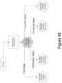
- FIG. 4B illustrates the various states of the appliance 18.
- the appliance 18 can run on hardware that is similar to the controller 22 and all high trust computations will take place inside an HSM 19.
- the appliance 18 has at least one HSM 19 but in some embodiments may support more to improve performance of cryptographic operations such as ECMQV (use of ECMQV discussed later).
- Appliances 18 should be provided in pairs for redundancy and high availability. Both appliances 18, 18' in a redundant pair should always be active as the agent 20 may connect to either one. Both appliances 18, 18' are configured on the controller 22 separately. It may be noted that the operator should ensure that both appliances 18, 18' have similar configurations in terms of assets. From the point of view of capacity planning, each pair should be considered as one appliance 18, for example, you can only count on the throughput of the pair to be no more than the throughput of a single appliance 18.
- An export PKCS10 request from the HSM 19 can be made for the SSL, HSM and ACC certificates and the certificates should be signed by a device CA. The certificates are then imported into the HSM 19.
- Protocol optimizations should therefore be made where possible. For example, ephemeral public keys can be pre-generated in the HSMs 19 for use in the appliance-ACC protocol. Communications with the controller 22 for conveying custom data and log data should also be efficient so as not to impact the performance of the appliance 18 in its interactions with the agent 20.
- the appliance 18 handles service requests from the controller 22 and the agents 20 using the appliance daemon 112 and uses multiple threads to allow controllers 22 and agents 20 to be serviced independently of each other in the same way as the controller 22 can operate in parallel using multiple threads. In this way, the controller 22 is given a separate thread and each agent 20 is given a separate thread. Schema for the database 114 should be designed for efficient storage of logs, for efficient storage of data as required by various service modules, and for efficient lookups of data as required by the service modules.
- the agents 20, shown in Figure 5 are software libraries and each agent 20 is integrated into or with a customer's test program or script, a custom application that is loaded onto a tester 16 (a computer configured to test the devices 14) on the manufacturing line. Where applicable, the agent 20 communicates with an ACC 12 or a soft ACC 12'.
- the agent API 21 makes requests for assets to appliances 18 and send logs of used assets back through a secure SSL connection.
- the AMS 10 supports the use of the daemon API 23, which spawns a separate process, namely the daemon 25, that retrieves assets from and provides assets to an appliance 18, reducing some of the work being done by the tester application 116.
- FIG 6A illustrates a configuration for the agent 20 utilizing the agent API 21.
- the agent API 21 allows the test application 116a, running on the tester 16, to connect to an appliance 18, to retrieve assets, and to return logs to the appliance 18. It can be seen that the agent API 21 is integrated directly in the test application 116a, which gives complete control over how and when assets and logs are transferred between the tester 16 and the appliance 18. As seen in Figure 6A , the agent API 21 obtains an asset data package 120 from the appliance 18, as well as any log request 126. The agent API 21 also provides an asset request 124 to the appliance 18 and provides requested log reports 122.
- the daemon API 23 can be used instead of the agent API 21 to offload responsibilities for managing assets and logs.
- the daemon API 21 is integrated into the test application 116b to enable it to communicate with a separate process - the daemon 25, that acts as an intermediary between the test application 116b and the appliance 18 for managing the exchange of asset data packages 120, log reports 122, asset requests 124, and log requests 126.
- the daemon API 23 provides a simpler interface and can be configured to run the daemon 25 as a background process.
- the daemon API 23 provides an interface with the test application 116b to obtain assets as they are needed and obtain log data 128 as it is generated during or at the end of each test.
- the daemon API 23 runs the separate daemon 25 to host the agent API 21 for the purpose of obtaining assets and providing log reports 122 to the appliance 18 to avoid the test application 116b having to constantly connect to the appliance 18 during the testing process, thus saving time.
- the daemon 25 can request batches of assets at a time using the agent API 21, and deliver assets as they are needed to the tester 16 through the daemon API 23 such that assets are always available to the tester 16 without having to connect to the appliance 18.
- the test application 116b only needs to interface and thus communicate with the daemon API 23 for obtaining an asset and for providing its log data (which is then packaged into a log report by the agent API 23 on the daemon 25).
- the daemon 25 maintains an asset cache 130 to store batches of assets for subsequent distribution to the tester 16 as needed, and a log cache 132 to store log data 128 output by the test application 116b as tests are completed, to be organized in the log reports 122.
- the daemon API 23 can also have a resource management subsystem (RMS) 27 configured for independently implementing and registering resource management processes with the daemon 25. In this way, users can implement their own resource management process (with their own directives) to make decisions when to fetch assets, send back logs, etc. and can associate this process by name with a particular product profile.
- RMS resource management subsystem
- the use of the daemon 25 and daemon API 23 as shown in Figure 6B provides several advantages.
- the daemon 25 can utilize thresholds to control how many assets it stores in the asset cache 130. For example, a low threshold, when crossed can cause the daemon 23 to utilize the agent API 21 to separately obtain a new batch of assets from the appliance 18 without disrupting the testing procedure and while continuing to forward the assets that it still has.
- Leftover assets may thus be marked as wasted if the daemon 25 shuts down and a log report can be generated and returned to the appliance 18 to ensure that leftover quantities can, if the applicant permits, be credited back to the customer.
- leftover assets can simply be maintained for the next instance of the test application 116b.
- the daemon API 23 can be used to create a standalone application as shown in Figure 6B or can also be embedded with the test application 116b in other embodiments.
- the daemon API should be used to offload the management of the assets and the log reports 122 in the test application 116b.
- the daemon API 23 can be created in client or server mode. In server mode, it connects to the appliance 18 and automatically manages the retrieval of assets and the sending of log reports 122. In client mode, it connects to an already running server mode daemon application for AMS assets and logs. There can also be an auto mode where the daemon API 23 uses client or server mode depending on whether or not another instance of the daemon 25 is already running.
- the daemon API 23 uses text-based configuration directives for the management of AMS products (or assets) and logs. These directives can be read from a file or from memory at compile time.
- the configuration directives include one or more product profiles.
- a product profile contains the name of the AMS product, the connection credentials for logging into an appliance 18, the resource management process, and the process settings.
- the resource management process is used to manage the assets and logs of the product associated with a profile.
- the process includes configurable directives for the asset top-up levels (min asset and max asset) and the threshold level at which logs are automatically sent to the appliance (max log).
- the agent 20 should be configured with the IP addresses of both appliances 18, 18' and fail-over from one appliance 18 to the other 18' in case of appliance failure.
- the agent 20 should report any errors, for example, if the agent 20 is unable to connect to one of the appliances 18, 18'. In the case of connection errors, the time the agent 20 waits before failover to the other appliance 18 should be configurable.
- the ACC 12 is a small and efficient cryptographic security engine that is integrated into a chip's design.
- the ACC 12 is integrated into the device 14 being manufactured and thus would be established in parallel but separately from the AMS 10.
- the AMS 10 can be used with or without the ACC 12 depending on the application. For example, serialization and key injection may not require the ACC 12 but the feature activation service module typically does. However, the ACC 12 can be used in applications involving serialization and key injection.
- the ACC 12 is typically embedded in a SoC die, which is then packaged into a chip, which is mounted on a printed circuit board (PCB), and eventually assembled into an electronic device 14. Every chip that has an ACC 12 can be registered and logged in the controller's database 110 as soon as it has passed wafer testing, which in turn can track every chip manufactured that underwent wafer testing.
- the ACC 12 has a set of output ports, and evaluating the aggregate of these outputs indicates which features are to be enabled and which are to be disabled. Once assembled, the ACC 12 can still serve as a root of trust on the ultimate device 14.
- the ACC 12 is designed to manage access to non-volatile memory (NVM) and to protect certain regions of the NVM from being accessed by unauthorized agents 20.
- the ACC 12 can provide self-contained generation of a unique device ID (UID) used to uniquely identify the ACC 12.
- the ACC 12 can also provide self-contained generation of keys used to open up a secure communication channel with a trusted server.
- the ACC 12 should ensure that the enabling and disabling of features are done using trusted equipment by trusted sources and the ACC 12 should be able to initiate or disable device self tests and heath checks to make sure the device 14 has not been tampered with.
- the ACC 12 can also lock out the device whenever too many invalid commands are issued.
- the ACC 12 is used to process commands from the appliance 18 and can be programmed to shut itself off if it detects a specified number of illegal commands.
- the ACC 12 should be designed to work in any electronics manufacturing test environment since the security features of the AMS 10 do not necessarily rely on being able to trust the data link between an appliance 18 and the ACC 12. Instead, security is built into the communications protocols using cryptography. As a result, the AMS 10 provides the ability to allow provisioning to occur in a secure, auditable manner anywhere - from the wafer fabrication to the ODM to the OEM to the user.
- the ACC 12 uses an asymmetric cryptography scheme for key exchange, and symmetric key cryptography to transfer messages between it and the appliance 18.
- the asymmetric cryptography scheme uses a public key, which is generated from a secret private key. The private key is kept secret and the public key is exposed. It is imperative that the private key be protected in a secure, highly tamper resistant setting.
- An embedded ACC 12 is able to fulfill this requirement by being able to internally and autonomously generate a unique private key, with a combination of hardware and firmware to protect the secret key from being exposed.
- the ACC 12 generates a unique identifier for each device 14, and participates in the tracking and provisioning of the device 14 through the encrypted channel with the appliance 18.
- the appliance 18 issues confidential messages, referred to herein as feature control tickets (FCTs) 50 to the ACC 12 in a secure manner.
- FCTs feature control tickets
- the ACC 12 is described in greater detail below making reference to Figures 51 to 66 .
- the appliance 18 should only be able to generate serial numbers based on the serial number schema received from the controller 22 (such schemas are described below).
- the appliance 18 should only be able to decrypt the sequenced keys received directly from the controller 22, i.e. not from another appliance 18.
- the appliance 18 should only be able to decrypt the FCTs 50 received directly from the controller 22, i.e. not received from another appliance 18.
- the credit or metering scheme used by the AMS 10 should be secured such that appliances 18 can only use the credit notices received directly from the controller 22.
- the appliances 18 should only use assets that are from the controller 22 from which it was provisioned to ensure that assets mistakenly sent to another appliance 18 cannot be used. It should not be possible for the appliance 18 to use credit notices from another appliance 18 and it should not be possible for an attacker to add, remove, or change the number of credits on the appliance 18.
- the AMS 10 can be configured to enable assets on one appliance 18 to be replicated to another appliance 18 for high availability/failover purposes if mechanisms are in place to ensure a unique asset is not used more than once.
- the web browser 100 should only be able to access the web server 104 over https and the communications should be secured, e.g. mutually authenticated, encrypted, integrity checked, replay protected, etc.
- the communications between the web server 104 and the controller daemon 106 and the CLI utility 102 and the controller daemon 106 should be secured as shown in Figure 3 , e.g. using SSL.
- the communications between the controller 22 and appliance 18 and appliance 18 and agent 20 should be secured, e.g. using SSL.
- the communications between the appliance HSM 19 and the ACC 12 should be secured using the ACC protocol and the ACC 12 should authenticate the appliance 18.
- the appliance 18 does not need to authenticate the ACC 12 as it is considered a trusted root.
- the logs from the agent 20 to the appliance 18 to the controller 22 may be encrypted and should be integrity protected to prevent eavesdropping and tampering. Only the controller 22 should be able to decrypt and validate logs. These logs may include custom data such as yield data.
- the controller 22 and the appliance 18 should be hardened against attack. This hardening will apply to the OS and the applications (e.g. the database 110) including those running on the HSM 19.
- All certificates are preferably elliptic curve cryptography (ECC) certificates issued by a trusted device CA, signed on a per-customer, AMS sub-root certificate. ECC certificates would then be used for SSL between each of the web server 104, controller daemon 106, appliance 18, and agent 20 - for HSM certificates, for every HSM 19 in the AMS 10, and for the ACC certificate used in the ECMQV negotiation with the ACC 12. Customer names should be embedded in the certificates and should be checked so that communications only occur between end points with the same customer name. Data stored in the database 110 should be protected against unauthorized access and modification.
- ECC elliptic curve cryptography
- a product is a model, which provides the AMS 10 with a name for the product, its identification, the service it provides, which appliances 18 are producing the product, and a list of assets.
- assets can be a collection of serialization schemas and a list of appliances 18 to which the schema collection applies.
- the assets can be a collection of key types and a list of appliances 18 to which that key type collection applies.
- the assets can be a collection of FCTs 50 and a list of corresponding appliances 18.
- Service modules discussed herein determine what each of the AMS components (controller 22, appliances 18, agents 20, and ACC 12) provide in the production process.
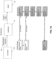
- the AMS 10 in the following examples can define service modules for serialization, key injection, and feature activation, however, it will be appreciated that other service modules can be applied to deliver and provide other types of assets. Examples of serialization, key injection, and feature activation service module configurations are shown in Figures 7A , 7B, and 7C respectively.
- the serialization service module is a configuration of the AMS 10 that is used to provide a secure means of generating, assigning to chips (or other electronic objects or devices), and tracking unique serial numbers.
- the controller 22 is used to define a product model, then to define one or more serialization schemas 134 to be bound to each product model.
- Each serialization schema 134 contains a range of serial numbers for a particular product (e.g. device 14).
- the serial number schemas 134 are sent over a secure, encrypted connection (e.g. over SSL) to the appliances 18 at the manufacturer's location, typically automatically, whenever a synchronization operation takes place.
- Agents 20 can then request serial number values by product name using the agent API 21 or the daemon API 23.
- serial numbers are generated by the appliance 18, metered, and provided to the agents 20.
- the serial numbers are then injected sequentially into each die in a chip manufacturing process using the agent 20.
- the controller 22 tracks how many serial numbers have been consumed for each serialization product, and makes these results available in the GUI 8.
- a serialization schema 134 is an object that defines the rules about how a serial number is generated. For example, it determines whether the serial number digits are presented in hexadecimal or decimal form and whether fixed strings are included. While one or more serialization schemas 134 can be bound to a serialization product, a particular schema 134 can only be bound to one product. Serialization schemas 134 bound to a product cannot overlap and once bound, the schemas 134 should not be unbound. For other changes, e.g. to change the static strings that have been inserted, a new serialization schema 134 should be created.
- serialization products can be bound to more than one appliance 18, with each binding having a minimum and maximum inventory level.
- the controller 22 can be used to ensure that products bound to multiple appliances 18 have non-overlapping ranges of serial numbers.
- the controller 22 keeps an inventory of serial numbers at the specified maximum level. Once the inventory has been sent from the controller 22 to an appliance 18, the serial number values should not be able to be recalled or revoked.
- a serial number schema 134 may describe how to convert a base value into a serial number string.
- the term serial number base value refers to any positive 64-bit integer, and should not be confused with the base attribute.
- a serial number schema 134 has several attributes: start, count, base, and total characters. The start and count values define the range of base values that are allowed in the schema.
- the base attribute determines whether the base value is represented in base-10 or base-16 format, when it is converted to a serial number string.
- the total character attribute defines how many characters to use when representing the base value as a serial number string. Zero or more static strings can be inserted at any position in the serial number string.
- serial number string Given a serial number schema 134 and a base value, a serial number string is constructed as follows:
- serialization products when defined, are assigned a unique product ID by the AMS 10 and a unique identifying name provided by the operator in order to distinguish from other products.
- the appliance 18 can deliver the serial numbers to the agent 20 directly or can deliver the serial numbers via FCTs 50. If the serial number is delivered via an FCT 50, then the operator would, in the examples provided below, need to specify a 2-byte memory offset (in hexadecimal) within the ACC 12 where the serial number is to be stored and also an 8-byte record tag value (in hexadecimal).
- the key injection service module can also support the processing of keys at the controller 22 before they are imported, allowing the keys to be arbitrarily transformed, referred to herein as key import signed objects.
- Key import signed objects should be able to be defined wherein each signed object is assigned a unique signed object ID by the AMS 10 and each signed object is assigned a unique identifying name provided by the operator.
- the signed object is a shared object that resides in the controller 22 and is cryptographically protected with a signature. A function in the shared object is then called once for every key before it is imported to allow the operator to transform the key.
- the key identifier for example KSV in the case of HDCP
- Key import signed objects should be able to be assigned to one or more key types 138 and each key type 138 should be able to have at most one key import signed object assigned.
- the key import signed objects should be able to be unassigned from key types 138 as well.
- Such key-to-appliance transforms 139 should be able to be defined and each transform should be assigned a unique signed object ID by the AMS 10 and each transform should be assigned a unique identifying name provided by the operator.
- the transform is a shared object that resides in the controller 22 and should be cryptographically protected with a signature. A function in the shared object is called once for every key before it is sent to the appliance 18 to transform the key. It may be noted that the key identifier should be copied out so that the controller 22 can always access it even after the transform has taken place.
- Key-to-appliance transforms should be able to be assigned to one or more key types 138 when bound to a product. Each bound key type 138 should have at most one key-to-appliance transform assigned. The key-to-appliance transforms should be able to be unassigned from key types in a product as well.
- the key injection service module can also support appliance signed objects which allow for the post-processing of keys at the appliance 18 after they are decrypted but before they are sent to the agent 20.
- appliance signed objects key pass-through should also be supported. Depending on whether key pass-through is enabled or disabled, it enforces whether or not appliance signed objects should be present before the appliance 18 will send keys to the agent 20. This may be referred to herein as key-to-agent signed objects.
- the appliance 18 should not send duplicate keys to agents 20 and once a key has been delivered, it should be deleted from the appliance 18.
- a key is delivered via an FCT 50, it should not be able to be delivered directly and when a key injection product is unbound from an appliance 18, all keys belonging to that product should be deleted from the appliance 18.
- the agent 20 should be able to request key blobs from the appliance 18 by product name and count and each key blob should contain one or more keys, depending on how many key types are bound to the product. For example, if the product utilizes 3 key types, the key blob would include 3 keys. Agents 20 should not send duplicate keys to the tester 16. Once a key is delivered to the tester 16 it should be deleted from the agent 20. The agent 20 should also log the use of each key in the key blob separately, and should log any keys that it intends to discard.
- the ACC 12 can also be used with serialization and key injection service modules but is particularly advantageous for use with the feature activation service module.
- the controller 22 is used to define one or more FCTs 50, then to define a product model.
- the FCTs 50 are then bound to each product model, in which case all FCTs 50 are also bound to the appliance 18 producing that product.
- the FCTs 50 are then applied to each die on the assembly line using the ACC 12.
- Products can be bound to one or more appliances 18, with each binding having a minimum and maximum inventory level.
- the controller 22 keeps its inventory of FCTs 50 at the specified maximum level. Once the inventory level has been sent from the controller 22 to the appliance 18, the FCTs 50 should not be able to be recalled or revoked. The controller 22 tracks how many FCTs 50 have been applied to each product, and makes these results available in the GUI 8.
- the feature data is programmed into the ACC feature register 120 and the record tag is programmed into the ACC tag register.
- the value of the record tag is also customer-dependent.
- the two commands (which are described in greater detail below) to write to the feature register are SETFEAT and SETFEAT_TEMP. When using the latter, the feature data is not saved in NVRAM and would be lost on power-down.
- the ACC 12 also contains in this example a 64 bit (8 byte) record tag (register).
- the record tag is meant to be used to record what has been programmed on the ACC 12. the record tag is set when using any of the commands that write to the ACC 12 (except SETFEAT_TEMP). How the record tag is interpreted is application-dependent.
- the ACC 12 also contains an implementation-dependent amount of NVRAM.
- the command to write to the NVRAM is WRACCESS. A maximum amount of data that can be written is usually imposed, e.g. 500 bytes. What is written to the NVRAM and where it is written is implementation-dependent.
- the FCTs 50 are sent over a secure, encrypted connection (e.g. SSL) to the appliances 18 at the manufacturer's location automatically whenever a synchronization operation occurs. FCTs 50 can then be requested by the agents 20 by product name, using the agent API 21 or daemon API 23. When an agent 20 requests a feature activation product it would obtain all the FCTs 50 bound to that product individually. When an agent 20 fetches FCTs 50 from an appliance 18, it queries all service modules for an ACC-enabled product of that name, in which case multiple FCTs 50 may be delivered to an agent 20, and are then send to an ACC 12 individually. The agent API 21 may not interface with the ACC 12 directly in which case an implementation-dependent interface is required. When using the feature activation service module, the feature data should never be in plaintext after it leaves the controller 22 and before it enters the ACC 12.
- SSL secure, encrypted connection
- the feature activation service module creates logs when feature data is sent to an appliance (controller logs), when feature data is sent to an agent 20 (appliance logs), and when feature data is sent to the ACC 12 (agent logs). All the logs are stored on the controller after being returned by an appliance 18 during a synchronization operation, and can be used to monitor and track feature use. Each time feature data is used on an appliance 18, the appliance credit is decremented by one and each appliance 18 also maintains a feature data product level, which is decremented by one each time feature data is used. The feature data level and credit level are replenished when the controller 22 synchronizes an appliance 18. Both of these mechanisms are used to meter feature data use on an appliance 18.
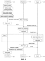
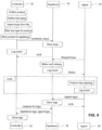
- loop 1 is initiated by providing the command cmd[STARTACC] described in detail below.
- the loops are terminated by providing the command cmd[STOPACC].
- the loops are shown in greater detail in Figure 10B .
- the agent 20 provides these public keys in turn to the appliance 18 and the appliance 18 uses these keys to generate a shared key, e.g. using the ECMQV protocol as exemplified later.
- the appliance 18 has now opened a secure connection with the ACC 12 and can meter and encrypt the features and log this event.
- the appliance public keys and the encrypted features are then provided to the agent 20.
- the agent 20 then initiates the feature programming loop by sending the command cmd[INITIAL FCT
- the features are then programmed in the feature register 120 by the ACC 12 and the agent requests a response again using the cmd[REQRESP].
- the ACC 12 provides an encrypted response pertaining to the feature programming steps and the agent 20 logs this event. Since the secure connection is established, additional feature programming steps can be applied before the loops terminate as noted above.
- each product should be assigned a unique product ID by the AMS 10 and a unique identifying name provided by the operator.
- Each feature that is defined can be assigned a unique feature ID by the AMS 10 and a unique identifying name by the operator.
- Each feature defines a command type and, in this example, a 32-byte data value.
- One or more features should be allowed to be bound to a feature activation product and each feature may be bound to multiple products.
- a feature should be able to be unbound from a product, but only if that product is not bound to any appliances 18.
- Each feature activation product can be bound to one or more appliances 18 and each appliance 18 may have multiple feature activation products assigned to it.
- a metering process can be implemented where the controller 22 will top up the feature activation product levels on the appliance 18 during a synchronization operation. The operator would define warning, minimum and maximum levels similar to the other service modules exemplified herein.
- a feature activation product may be modified/deleted on the controller 22 if it is not bound to any appliance 18 and features may be modified/deleted on the controller 22 if it is not assigned to any feature activation product.
- An appliance 18 can be deleted on the controller 22 if there are no products bound to the appliance 18.
- the feature command, record tag, and data should be protected from tampering on the appliance 18 and a read-only sync mode should be supported to allow a query to be made and logs to be obtained without providing more FCTs 50.
- the appliance 18 supports delivery of features to the ACC 12 via the agent 20 using the protocol defined in Figures 51 to 66 described below. This includes receiving feature activation products from the controller 22, responding to requests from the agent 20 for feature activation products, metering the products, receiving logs back from the agent 20, and sending logs back to the controller 22.
- the appliance 18 decrements appliance credit for each FCT 50 delivered and when a feature activation product is unbound from an appliance 18, all features belonging to that product should be deleted from the appliance 18.
- the agent 20 can request features from the appliance 18 by feature activation product name; can interface with the ACC 12 using the above-mentioned protocols; and can deliver each feature in the product to the ACC 12 separately, log the feature use, and return logs to the appliance 18.
- the feature activation feature use log should include a single character string field for customer log data, formatted appropriately.
- FIGs 11 to 50 illustrate example screen shots for the GUI 8 shown in Figures 1 and 3 .
- the GUI 8 is, in this example, a web-based application providing a graphical interface for the AMS 10.
- the GUI 8 is designed with an AMS system operator as the intended user and thus provides the ability to connect to the AMS controller 22, e.g. by logging in with a username and password.
- the GUI 8 enables the operator to view status information by products 14, services, or by manufacturer; review current alerts, manage and track jobs currently active on the controller 22; view and generate reports; view information and statistics about the controller 22; manage the appliances 18 and perform operations associated with the appliances 18; manage products 14 in the system and perform operations associated with these products 14; manage serialization schemas, key types, and FCTs 50; manage users, passwords and roles that allow access to controllers 22 and appliances 18; access online help for the particular application; and determine information related to the application (e.g. build date, version, etc.)
- the GUI 8 can be accessed by launching a standard web-browser and pointing the browser to an appropriate URL.
- the GUI 8 can include a quick status view 200, which can be configured to appear when the user is logged off or otherwise "locked out" of the controller 22.
- the quick status view 200 can be configured to appear after the GUI 8 times out from inactivity on the part of the user logged in, or if the user clicks a lock button or selects a similar option from a menu (not shown).
- the quick status view 200 is also made available for viewing even without a user login. In this way, status information, alerts, and other critical messages can be viewed without the observer having to be logged in.
- the quick status view 200 also functions as a screen-saver for the GUI 8 such that if a prescribed period of time passes with no activity in the GUI 8, the quick status view is displayed 200 and the operator would need to log in again to continue. This protects the AMS 10 from inadvertent or malicious tampering while still providing important status information on a "read only" basis.
- the quick status view 200 comprises a top portion 202 and a bottom portion 204.
- service icons 206 are displayed for the services offered by the AMS 10. Each icon indicates, by colour (e.g. red or blue), whether there is a problem or alert with any of the appliances 18 associated with the particular service.
- product icons 208 are displayed for any products 14 defined in the GUI 8. Similar to the top portion 202, each icon 208 indicates, by colour, whether there is a problem or alert with any of the appliances 18 in the system or application supporting the particular product.
- the use of different colours for normal operations versus problem states enables an operator to quickly identify a problem and drill in to that appliance 18 and application to determine the source of the problem and take any remedial action if necessary.
- the bottom portion 204 can provide multiple rows (not shown), e.g. when there are many products 14. In some embodiments, the operator may be given a option for defining which products 14 should appear in the quick status view 200.
- a user login screen (not shown) can be launched.
- the operator can be presented with a status view filtered according to the selected icon. Therefore, the operator, upon determining a problem with a particular service in the quick status view 200, can click on that service icon 206 and, upon logging in, the next view would be filtered to that service, e.g. serialization.
- the operator can observe which appliance(s) have alerts and double-clicking (or other input) can take the operator to a detailed view of information about the appliance 18, allowing them to determine the source of the alert.
- the login screen When logging in, the login screen can be given a format that is similar to the quick status view 200 and other screens and to differentiate between fields, each field can be highlighted with a different colour and provide a status bar to indicate what is being performed. If there is an error logging in, a non-field specific message can be displayed with a red background at the top of the form.
- a main application 210 appears, which may be filtered if the user had selected a particular icon 206, 208.
- One example, providing an appliance view is shown in Figure 12 .
- the GUI 8 provides a consistent form of panes and methods for interacting with the application.
- the main navigational and information areas of the main application 210 in this example include an application menu bar 212, a view pane 214, a main information pane 216, a status bar 218, and a version bar 220.
- the applications menu bar 212 in Figure 12 comprises five menus, namely a Controller menu, a Services menu, a View menu, an Actions menu, and a Help menu.
- the Controller menu enables the operator to modify the controller 22, and log out of the GUI 8.
- the Services menu includes an item for each service which, in this example include serialization, key injection, and feature activation.
- the View menu enables the operator to select from various views, e.g. status, alerts, jobs, reports, controller, appliance, products, serialization schema, key types, feature control tickets, users, etc.
- the Actions menu changes according to the selected view.
- the Help menu can provide access to various help resources such as system help, administrator's guide, developer's guide, product overview, system overview, user's guide, etc.
- the view pane 214 provides quick access to the different views in the GUI 8. Such views may include a status view, alerts view, jobs view, reports view, controller view, appliances view, products view, serialization schema view, key types view, FCTs view, and user's view. It may be noted that in this example, the view pane 214 is an alternative to user the View menu. Where applicable, a number beside each view item indicates the number of the associated item (e.g. number of alerts for the alerts view, number of jobs for the jobs view, etc.) active in the AMS 10. Many of the views can also display the Services menu allowing the operator to quickly filter items in the data according to the selected service.
- the Services menu allowing the operator to quickly filter items in the data according to the selected service.
- the appliances view can display all appliances with the serialization service active.
- the standard filter bar can be disabled and hidden. Additional service specific information may be displayed for each item in the information pane 216 and extra service specific actions may appear when selecting services in the Services menu.
- the main information pane 216 displays information about the objects in the system according to the selected view. For example, for the Jobs view, each item in the data area is a job in the system.
- the main information pane 216 comprises several features.
- a view title bar 222 displays the title of the active view along with the title of the form if a form is currently displayed.
- the view title bar 222 for a "Modify Appliance” may show: "APPLIANCES ⁇ MODIFY APPLIANCE".
- the view title bar 222 may also contain a link to context-sensitive online help for the current screen.
- a services bar 223 provides a way for the operator to quickly hone in on the services they are interested in.
- the services bar 223 in the example shown in Figure 12 displays icons in a horizontal grid and may include the following items: All, Serialization, Key Injection, and Feature Activation. Selecting "all" removes any filters and displays the results of the active view with no filtering. Selecting any of the remaining services displays the active view filtered according to the selected service. For example, appliances using the selected service, jobs related to the selected service, etc. In this way, the operator can more easily navigate amongst multiple services and appliances served by a single controller 22. Additional service-specific information may be displayed for each item in the data area and extra service-specific actions may appear when selecting services in the service bar.
- An action bar 224 contains various buttons on its left side with a pull down menu containing any additional actions that are valid for the current view.
- On the right side of the action bar 224 is a search field. Typing text in the search field filters the contents of the data area 226 depending on the view. For example, for the appliance view, the user may search by appliance name, manufacturer, location, or product. Actions in the action bar 224 may be valid or invalid depending on the selected item in the data area, or whether there is anything selected. If an action is invalid, it can be greyed out. In general, it is advantageous for the list of actions for each view to be consistent, and actions become valid or invalid.
- a data area 226 presents the information as appropriate for the view, filtered as necessary.
- each view may support up to three zoom levels to enable the user to conveniently drill down into further details when needed to troubleshoot or to identify various settings.
- Zoom levels may be one item per page, one item per three-lines, and one item per line. The shorthand for these zoom levels are: 1-line, 3-line, and detail.
- a pull down menu 225 in the action bar 224 allows the operator to select a zoom level.
- a paging bar 228 allows the operator to page through many items when there are too many items to fit on one page. If the zoom level is "detail", then there may be one page for each item.
- the paging bar 228 can be configured to appear automatically whenever necessary. If the information to display fits on a single page, the paging bar 228 does not need to appear.
- paging widgets 230 can include: text describing which items are displayed (for example, "Reports 11 - 20 of 46"); button to go to the first page; button to go to the previous page; the text "Page XX of YY", where XX is a text field allowing the user to go directly to a specific page, and YY is the total number of pages; button to go to the next page; and button to go to the last page.
- the status bar 218 is positioned at the bottom of the window and displays basic information about the controller 22, e.g. to indicate that a connection is made and with which operator. Lock and refresh buttons can be included as shown for all views.
- the data area 226 can be modified to include an alert bar 232 as shown in Figure 13 , which in the example shown indicates that the selected product (shown in the data area 226) has low inventory on a particular appliance 18 named "TestApp".
- the alert bar 232 can be given a distinct and bold colour such as red, consistent with other alerts, to draw immediate attention to the alert.
- the alert bar 232 extends across the width of the data area 226 and includes emergency-related icons to further identify the alert as such.
- the main application 210 can be used to launch a main status view 234 as shown in Figure 14 , which displays appliances 18 in three ways: grouped by product, by manufacturer, or by location. If the view is accessed from the quick status screen 200 by clicking one of the product icons 208, if the view is filtered by products 14, or if the "By Product" action is selected, then it will group appliances by product. Otherwise, it groups appliances 18 by manufacturer.
- the screenshot shown in Figure 14 illustrates a view by product. If displaying appliances 18 grouped by product as shown in Figure 14 , each product is displayed showing each appliance 18 associated with the product. If displaying appliances 18 grouped by manufacturer, then each manufacturer is displayed showing each appliance 18 associated with the manufacturer. If displaying appliances 18 grouped by location, then each location is displayed showing each appliance 18 associated with the location.
- Appliance icons 236 include service indicators 237 for which services are active on the particular appliance as well as provides an indication of whether the appliance 18 currently has any active alerts (by colouring the icon red) or whether the appliance 18 is operating correctly (by colouring the icon blue).
- the service indicators 237 can utilize a colour-coded scheme for indicating various states. For example, an orange icon may indicate that the service on that appliance 18 is low on assets, a red icon may indicate a problem with that service, a dim or 'greyed out' icon can indicate that the service is not assigned to the appliance 18, and a green icon can be used to indicate that there are no problems.
- the status view 234 uses a single zoom level in this example. The View action (or double-clicking a particular appliance) takes the operator to the one item per page zoom level of the appliances view with the selected appliance 18 being displayed.
- the actions associated with the main status view 234 are: View, By product, By manufacturer, and By location.
- the operator can access the alerts view 238 shown in Figure 15 to examine any alerts present in the AMS 10.
- the zoom level shown in Figure 15 is a 1-line zoom level.
- the operator can view the alerts, ping the affected appliance 18, sync the affected appliance 18, and remove the alert.
- the controller 22 can be configured to issue alerts under several different circumstances such as: when the controller 22 is not able to contact an appliance 18, if there are any errors when the controller 22 sends data to an appliance (and vice versa), when a synchronization operation has failed, when the number of assets an appliance 18 has reached the asset warning level, when the free disk space on the appliance 18 has reached a warning level, when the HSM 19 on the controller 22 (or any appliance 18) has deactivated itself, or when an appliance 18 has blocked a connection from an agent 20 - because the agent IP address is not in the list managed by the appliance 18.
- the appliance 18 affected appears in the alerts view 238 in the data area 226.
- the alerts view 238 provides a description of the alert, identifies the service for which the alert was issued, and provides the time the alert was issued. The appropriate response to an alert depends on the cause of the alert.
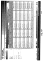
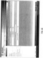
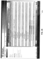
- the operator can access the jobs view 240 shown in Figures 16 to 18 to perform various actions associated with jobs in the AMS 10, such as cancelling a job in progress and removing a completed job.
- the jobs view 240 in this example supports a 3-line zoom mode 240a as shown in Figure 16 , a 1-line zoom mode 240b as shown in Figure 17 , and a detail zoom mode 240c as shown in Figure 18 .
- the complete set of information that the detail zoom mode 240c gives, per job, is: name, job ID, system (appliance 18 or controller 22), job type, job status, start time, end time or estimated end time (if available), duration, and progress.
- a progress bar 242 is provided in each zoom mode 240a-c to provide a graphical overview of the status of the job.
- the operator can pause the job, zoom between zoom modes, resume the job, cancel the job, view a job log, remove a job, show completed jobs, and remove completed jobs.
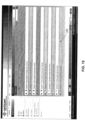
- the operator can access the reports view 244 shown in Figure 19 to generate reports supported by the AMS 10.
- Figure 19 illustrates a 1-line zoom mode for the reports view 244.
- the reports view 244 provides a service icon and a name for a report.
- the reports view 244 can also be filtered by selecting a service on the services bar 223 to limit the list of reports to a particular service.
- the generate report action displays a generate reports form 246 shown in Figure 20 for the operator to enter information required to generate a report. Once the operator has completed the form 246, the report can be viewed as shown in Figure 21 in the view reports screen 248.
- the view reports screen 248 also enables the operator to download PDF or CSV formats in this example.
- Various report types can be generated, for example: number of assets issued by a controller 22 in total, by product or by schema (for serialization); number of assets issued by day for a particular range; number of assets by appliance 18 (total, by day, etc.); number of assets received by agents (total, by day, etc.); number of missing logs, duplicate logs, logs by asset ID or number, logs for a specified product/date range; etc.
- the controller view 250 shown in Figure 22 provides details of the controller 22 to which the operator is connected in the data area 226.
- the controller view 250 provides the following information: controller name, services the controller is providing, IP address of the controller 22, port of the controller 22, SMTP IP address, SMTP port, SMTP domain, "From" address, "To” address, disk health, controller HSM status, HSM software version, controller software version, number of alerts in the system 10, the number of jobs active in the system 10, job delete time, system check interval, controller's disk space, and memory available on controller 22.
- the operator can modify the controller 22, test email, and log out.
- the Modify button in the controller view 250 is selected, launching a modify controller form 252 shown in Figure 23 .
- the modify controller form 252 enables the operator to make changes to the settings and details for the controller 22 and apply those settings.
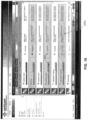
- the operator can access the appliances view 254 shown in Figures 24 to 26 to perform various actions associated with the appliances 18, such as adding, modifying, removing and syncing an appliance 18.
- the appliances view 254 can support detail, 3-line, and 1-line zoom modes.
- Figure 24 shows the appliance view 254 in All Services mode. In All Services mode, each appliance 18 displays service-specific information about one of the services. If only one service is active on the appliance 18, then that service is displayed. If more than one service is active, then the service to display can be selected in a defined order of priority. If a service is selected in the services bar 223, then that service is displayed for all appliances 18 in the appliances view 254.
- the 3-line mode 254a is shown in Figure 24
- the 1-line mode 254b is shown in Figure 25
- the details mode 254c is shown in Figure 26 .
- the information available per appliance 18 in this example includes: appliance name, services provided by the appliance 18, manufacturer, location, IP address and port, status (e.g.
- HSM software version disk space available, memory available, credit available, minimum amount of credit, maximum amount of credit, warning level for credit, appliance software version, number of alerts, number of jobs, number of connection retries, connection timeout period, auto sync interval, ready only sync, asset block size, last update, list of allowable agent IP subnets, date/time of last communication with controller 22, date/time of last communication with each agent 20, and service-specific information (e.g. serial numbers, keys, FCTs 50). Certain ones of these details can appear in certain zoom levels as shown in Figures 24 and 25 . In the appliance view 254, the operator can perform a zoom between zoom modes, ping the appliance 18, sync the appliance 18, add an appliance 18, modify an appliance 18, remove an appliance 18, activate an appliance 18, and deactivate an appliance 18.
- the ping appliance action launches a ping screen 256 as shown in Figure 27 , which enables the operator to ping the selected appliance 18 over the secure channel to make sure it is alive and to determine its network latency.
- the ping action is used to test whether a particular host (appliance 18) is reachable across an IP network and to test an SSL connection, self test the network interface card (NIC) of the computer being used, or as a speed test.
- the ping can estimate the roundtrip time, generally in milliseconds, record packet loss, and print a statistical summary when complete.
- the sync appliance action launches a sync screen 258 shown in Figure 28 and enables the operator to ensure any service-related objects are topped up (e.g. assets such as serial numbers, keys, FCTs 50, etc.), pushes any appliance configuration changes, and retrieves service logs from the appliance 18.
- the synchronizing action makes sure that any service related objects or assets, such as serial numbers, key, and FCTs 50 are at their maximum amounts.
- the synchronizing action also synchronizes an appliance's clock with the controller's clock and retrieves service logs from the appliance 18.
- any configuration changes made to an appliance 18 can come into effect after the appliance 18 is synchronized.
- a read only sync can also be performed, which will gather the status and asset information of the appliance 18 to see if it is in sync, but does not make any changes.
- the synchronization can also be used to obtain service logs from an appliance 18.
- the modify appliance action launches a modify appliance screen 260 shown in Figure 29 .
- the modify appliance screen 260 enables details of the appliance 18 to be edited by the operator. Not shown in Figure 29 are credit minimum, credit maximum, and credit warning fields to enable the operator to set thresholds for the credits given to the appliance 18 and when to issue a low-level warning.
- the controller 22 and appliance 18 should automatically synchronize on a regular basis and, when the appliance 18 is synchronized, the controller 22 checks to see how many assets are on the appliance 18. If the number of assets is equal to or lower than the minimum value, then the controller 22 fills the appliance's assets to the maximum level. If the number of assets is equal to or below the warning level, then the controller 22 can issue an alert.
- FIG. 4B When an appliance 18 is first added to a controller 22, it is added with an inactive status (see also FIG. 4B described above).
- the activate appliance action brings the selected appliance 18 online (automatically initiating provisioning if necessary).
- the deactivate appliance action takes the selected appliance 18 offline with appropriate warnings if taking the appliance 18 offline will stop an associated production line.
- Figure 30 illustrates a deactivate appliance screen 262 showing a selected appliance to be deactivated before having the operator confirm this selection.
- the remove appliance action should only be available if the selected appliance is not online, otherwise the action should be disabled.
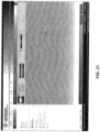
- Figure 31 illustrates a remove appliance screen 264 which is similar to the deactivate appliance screen 262 in that the selected appliance 18 is shown prior to confirmation of the selection by the operator. It may be noted that the appliance 18, when deactivated, should indicate this by, e.g. changing colour to red as exemplified above, to provide a further visual cue to the operator regarding the status of the appliance 18.
- a product in the GUI 8 is a named grouping of one or more asset types that provides the AMS 10 with a name for the product, an identifier for the product, a list of assets (e.g. serialization schema, key type, or FCT 50, depending on the service), a list of appliances to which the assets should apply, and the service the product provides.
- the operator can manage products and perform various actions associated with products in the AMS 10, such as adding, modifying or removing a product.
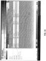
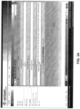
- the products view 266 is shown in a 3-line zoom mode 266a in Figure 32 , a 1-line zoom mode 266b in Figure 33 , and a details zoom mode 266c in Figure 34 .
- the product view 266 can include various information pertaining to the product, such as: product name, service, ID, assets available (displayed as a meter, each displayed individually in detail zoom level 266c), list of assets (schema, key types or FCTs 50), list of appliances 18, and for serialization and key injection - injection method (ACC or normal), ACC record field and ACC offset field.
- the operator can perform a zoom between zoom modes, add a product, modify a product, and remove a product.
- serialization schema list would be replaced with a key type list and for feature control, the serialization schema would be replaced with an FCT list.
- a serialization schema in the AMS 10 is an object that defines the rules about how a serial number is generated. For example, whether the serial number digits are presented in hexadecimal or decimal and whether fixed strings are included.
- a serial schema view 270 is shown in Figures 36 to 38 . In these views, the operator can manage serialization schema and perform various actions associated with schema in the AMS 10, such as adding, modifying or removing schema.
- the 3-line zoom mode 270a is shown in Figure 36
- the 1-line zoom mode 270b is shown in Figure 37
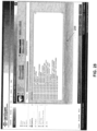
- the details zoom mode 270c is shown in Figure 38 .
- the information that defines the serial schema in this example includes the schema name, schema ID, serial numbers remaining (not yet sent to appliances 18) from total pool, start value, total count of serial numbers to generate, whether to use base-10 or base-16, total number of characters in the serial number (to pad or truncate), list of static strings to include with their positions in the serial number, and samples to illustrate the schema.
- the operator can perform a zoom between zoom modes, add a schema, modify a schema, remove a schema, and duplicate a schema (modify the current selection but save with a new name).
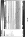
- an add/modify/duplicate schema form 272 is launched as shown in Figure 39 .
- a key type in the AMS 10 is an object that defines the rules about what types of cryptographic keys should be injected for a particular product.
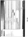
- a key types view 274 is shown in Figures 40 to 42 .
- the operator can manage key types and perform various actions associated with key types in the AMS 10 such as adding, modifying or removing a key type.
- a 3-line zoom mode 274a is shown in Figure 40
- a 1-line zoom mode 274b is shown in Figure 41
- a details zoom mode 274c is shown in Figure 42 .
- the information that the key types view 274 may provide can include: key type name, ID, keys available since last import, length of key, key identifier length and offset, key data length and offset, file header length, hash output (length and offset), hash algorithm, and hash input.
- a key type diagram 276 is also shown which provides a visual depicted of the structure of the key and is updated as parameters are changed to show the way in which the structure changes.
- the operator can zoom, import keys, add key types, modify key types, remove key types, and duplicate key types (modify current selection but save with a new name).
- An add/modify/duplicate key type form 278 is shown in Figure 43 which can be seen is similar to the details zoom mode 274c but enables parameters to be edited.
- An FCT 50 in the AMS 10 is an object that defines a particular feature or features that may be specified for a particular product.
- An FCT 50 includes an array of bits called the feature register 282. The state of specific bits in the feature register 282 may be mapped to features in the device 14, controlling whether those features are active or disabled.
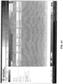
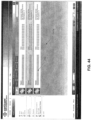
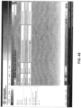
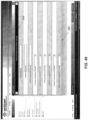
- An FCT view 280 is shown in Figures 44 to 46 and illustrates a visual depiction of the feature register 282 with the active features being distinguished from unactivated features by filling in a corresponding cell with a different colour.
- a 3-line zoom mode 280a is shown in Figure 44
- a 1-line zoom mode 280b is shown in Figure 45
- a details zoom mode 280c is shown in Figure 46 .
- the operator can manage FCTs 50 and perform various actions associated with FCTs 50 in the AMS 10 such as adding, modifying, or removing a ticket.
- the information that can be provided in the FCT view 280 for a particular FCT 50 may include: FCT name, ID, feature inclusion value, command implemented, tag (record tag indicating a feature or set of features programmed on the ACC 12), and total number of injections.
- the operator can navigate between zoom modes, add FCTs 50, modify FCTs 50, remove FCTs 50, and duplicate FCTs 50.
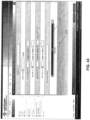
- An administrator can access a users view 284 shown in Figure 47 to perform various actions associated with the users in the system, such as adding a user, removing a user, and changing a user's password.
- the users view 284 is at the 1-line zoom level.
- the users view 284 lists information such as: username, controller permissions, appliance permissions, user permissions, serialization permissions, key injection permissions, feature control permissions, and last login time.
- the various permissions dictate what operations the user can perform, e.g. adding or removing an appliance, generating a serialization schema, etc.
- the administrator can add a user, duplicate a user, modify a user, change a password, and remove a user.
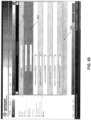
- An add user form 286 is shown in Figure 48 and enables the AMS 10 to impose security permissions on its users according to defined user roles.
- the administrator can define a user role to enable or deny different levels of access to particular parts of the system.
- the responsibilities can be partitioned within the GUI 8 to allow operating the GUI 8 to be much more effective.
- three user roles can be establishes as follows: Security Officer (SO), Administrator (AD), and Operator (OP).
- SO Security Officer
- AD Administrator
- OP Operator
- various permissions can be set per the above, e.g. for view only, view and save, view and operate, full access, etc.
- Figure 49 illustrates the add user form 286 with an error bar 288, shown in red to draw the administrator's attention.
- Figure 50 illustrates a similar error with a field-specific indicator bar 290 to highlight the cause of the error, in this example due to a lack of correspondence between the password and the confirm password fields.
- Other forms (not shown) can be launched for changing a user's password and removing a user.
- An online help service can also be provided for the GUI 8, which can comprise a menu item or a help icon or both (e.g. as shown in Figures 11 to 50 ) which link to an AMS online help guide, e.g. in HTML format such that it is supported by a web browser.
- the menu item can lead the user to the front page (table of contents) and the help button can lead the user to a help article determined according to the current view in the data area 226 (i.e. context-sensitive help).
- the system 10 is configured to provision, communicate with, provide data to, collect data from, and activate features within an ACC 12 embedded in an electronic device 14.
- the device 14 and in turn the ACC 12 is connected to a tester 16, which is used in a fabrication/manufacturing/assembly process.
- the tester 16 employs an agent 20, which is a software module running on the tester 16.
- the tester 16 is in turn connected to an appliance 18, which includes an HSM 19 that protects sensitive data and provides a secure zone within the appliance 18.
- the agent 20 facilitates a secure communication channel 29 between the HSM 19 and the ACC 12 for cryptographically securing communications therebetween.
- an FCT 50 can be sent from the appliance 18 to the ACC 12.
- the appliance 18 may be connected to a backend infrastructure 11, which may provide a certifying authority (CA), a database, and a controller 22 for controlling one or more appliances 18 as will be explained in greater detail below.
- CA certifying authority
- the ACC 12 may also, either at the same time or at some later time (or other time during the process), be connected to a user interface (UI) over a wide-area-network (WAN) 24 or a device programmer 26.
- the device programmer 26 may also connect to the ACC 12 via the WAN 24 as shown.
- the device programmer 26 and/or WAN 24 can connect to the device 14 and ACC 12 using any suitable connection, for example, serial, parallel, wired, wireless, infrared, RFID, etc.
- the ACC 12 is connected to the tester 16 over a standard testing protocol/connection 28 such as JTAG (Joint Test Action Group) IEEE-1149 test interface.
- JTAG Joint Test Action Group
- the tester 16 and appliance 18 are connected over a suitable connection 30 depending on their relative locations. In the examples provided below, the appliance 18 is located at the same physical facility as the tester 16 and therefore the connection 30 may be a local area network (LAN).
- LAN local area network
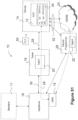
- the ACC 12 can comprise various types of memory, shown generally and collectively as numeral 34 in Figure 51 .
- the ACC 12 uses a portion of memory to store, either persistently or ephemerally, various keys and certificates.
- Figure 51 illustrates various keys and certificates that are used in the following examples.
- a static private key dsi, a static public key Qsi (also referred to as the ACC's UID), an ephemeral private key dei, an ephemeral public key Qei, a CA's certificate CERT[CA], and appliance j's certificate CERT[APPj], are shown in Figure 51 .
- the static keys are stored in non-volatile memory (NVM), although they could be mask programmed into a ROM memory. In another embodiment, no NVM may be required and the keys can be stored offline on either a hard disc or flash memory or some other non volatile bulk data storage medium outside of the ACC 12.
- NVM non-volatile memory
- the ACC 12 is a small hardware core embedded in a target system-on-chip (SoC) that establishes a hardware-based point of trust on the silicon die.
- SoC target system-on-chip
- the ACC 12 can be considered a root of trust on the consumer device 14 as it comprises tamper proof features that provide physical protection to sensitive data and methods to provide remote attestation and verification.
- the ACC 12 is able to generate a unique identifier (UID) for one integrated circuit (IC) 40, and participate in the tracking and provisioning of the IC 40 through a secure and authenticated communication channel 29 with the appliance 18.
- UID unique identifier
- the IC 40 is mounted on a printed circuit board (PCB) 44 that would then be assembled into a consumer device 14.
- PCB printed circuit board
- the ACC 12 can continue to serve as a root of trust on the PCB 44 and/or the final device 14.
- the IC 40 may also comprise a separate micro-control-unit (MCU) 42 which can be used to establish a connection with a non-tester, e.g. a device programmer 26 by connecting connection 32 to the IC 40 via a communication interface 48 configured for a suitable protocol as is known in the art.
- a non-tester e.g. a device programmer 26
- connection 32 e.g. a device programmer 26
- a communication interface 48 configured for a suitable protocol as is known in the art.
- the communication interface 48 may also be integrated into the IC 40 with a direct connection through the PCB 44 to the WAN 24.
- the role of the external MCU 42 shown in Figure 52 would be to facilitate the communication of the FCT 50 between the appliance and the ACC 12 over a network (e.g.
- the ACC 12 by receiving FCT 50 command messages through the communications interface 48 and reformatting the networked data, in this case maybe a stream of bytes, into a format that it could pass over its (the MCU's) memory mapped interface through the ACC 12 parallel interface 66 (see also Figure 53 ) for processing by the ACC 12.
- the ACC 12 would return FCT 50 response messages over its parallel interface 66 to the external MCU 42 for the MCU 42 to translate into a stream of bytes and transmit over the communications interface 48 back to the appliance 12.
- the ACC 12 may connect to the agent 20 and thus the appliance 18 via a test interface 72 (e.g. JTAG) - see also Figure 53 - which in turn bridges the connection 28.
- a test interface 72 e.g. JTAG
- the appliance 18 is a secure module used to cache, distribute and collect provisioning data and responses to/from one or more agents 20. For example, when an ACC 12 comes on-line, the appliance 18 can track the parts that it is connected to using the ACC's unique ID (UID). The appliance 18 and the ACC 12 may then proceed to exchange key information and open up a tamper resistant communication channel 29, which allows data to be transferred in such a way that the ACC 12 can be certain that it is talking to an authorized appliance 18, and the appliance 18 can be assured that only one unique ACC 12 can decrypt and respond to the message it has sent.
- UID ACC's unique ID
- the ACC 12 can be issued FCTs 50, and provide FCT responses which contain provisioning commands, secure data, key information, serialization information and any other data the appliance 18 wishes to provide to, push to, upload to, inject into or collect from the ACC 12 or the device 14 in general.
- the agent 20 may be considered a piece of software that manages the lower-level data transmission between the appliance 18 and the ACC 12.
- Each agent 20 is coupled to a tester 16 or device programmer 26, and is responsible for passing data transparently between the appliance 18 and the agent 20.
- the agent 20 comprises a transport layer API with which the appliance 18 may be used to issue commands and receive responses to/from the ACC 12. It will be appreciated that unless specified otherwise, secure operations performed by the appliance 18 are preferably performed within the HSM 19.
- the tester 16 or device programmer 26 can be physically connected to the chip through the standard JTAG IEEE 1149 test ports (e.g. test interface 46 and connection 28), or another programming interface depending on the application.
- the agent 20, in either configuration, is used to bridge the transport and physical layers.
- the agent 20 may be considered insecure and in the examples described herein does not perform any cryptographic functions aside from simply providing a message caching mechanism and passing messages between the appliance 18 and the ACC 12.
- the agent 20 can also be equipped with cryptographic capabilities of varying degrees depending on the requirements of the application.
- the back-end infrastructure 11 is a general term referring to the entire backend infrastructure that is used to interface between the manufacturer and its customers/end users.
- Every device ever processed by the system 10 and all programming records would be kept in a back-end database which the manufacturer may use to query the history of each part manufactured.
- the infrastructure may comprise a CA, database engine, ERP applications and submodules, a feature control server (FCS), and an e-commerce front-end server if necessary.
- the system 10 may also comprise connector logic to connect it to an to an ERP or e-commerce front end server.
- the typical system environment may have the back-end server located at a central location talking to an appliance 18 at a customer's manufacturing site via security protocols such as Secure Sockets Layer (SSL), Transport Layer Security (TLS), or Level 2 Security (MACSec) over the internet.
- SSL Secure Sockets Layer
- TLS Transport Layer Security
- MCSec Level 2 Security
- FIG. 53 Greater detail concerning the ACC 12 is shown in Figure 53 .
- the dark outer boundary in Figure 53 denotes a secure boundary such that any operations performed within this boundary are presumed to be trusted.
- the UID can be used as part of the security protocol to establish a secret between the appliance 18 and the ACC 12 through mutual key agreement.
- key agreement public keys are traded between two parties, each party generates a shared key independently of the other, using only the public keys that were exchanged in the open, and his/her own private key that is kept secret.
- the result of key agreement is that the two parties arrive at a secret shared between only the two of them, while any third parties trying to listen in could not complete the agreement unless they have copies of the private keys.
- the appliance 18 and ACC 12 can also participate in an ECMQV key agreement scheme, which generates a secret key that is known only to the two parties involved.
- the shared secret generated e.g. kij
- the shared secret generated is the basis and prerequisite for symmetric key cryptography, that is, it is used to establish a highly tamper resistant encrypted and authenticated communication channel 29 between the two parties.
- the appliance 18 can start issuing and receiving signed confidential messages, also known as FCTs 50, to/from the ACC 12 in a secure and authenticated manner.
- FCT 50 commands are messages containing either feature provisioning, read/write access to protected NVM 62 memory regions, or any other command or message to be provided to the ACC 12 in a controlled, secured and traceable manner.
- FCT 50 responses are messages containing status, audit data or any other command or message to be provided to the appliance 18 in order establish, maintain or comply with the secure provisioning protocol.
- Privileges can be used to positively enable features at test and manufacture time, or enable features upon reconnecting to a server or device programmer 26 in the after-market.
- the lack of privileges can be used negatively to disable non-authorized features in a suspect device, whether it being a clone, a counterfeit or otherwise stolen device.
- Completely secured feature provisioning can be achieved through the combination of various cryptographic techniques, examples of which are as follows.
- Each ACC 12 may have a Root CA public key stored in its ROM 52 or NVM 62. Each appliance j may then have its own unique certificate CERT[APP j ] produced by the Root CA (not shown). The certificates may be relatively small and the certificate fields bit-mapped for easy parsing.
- the appliance 18 authenticates itself to the ACC 12 by sending a certificate to the ACC 12 as part of the protocol (to be discussed in greater detail below). The ACC 12 uses the CA root certificate to verify the identity of the appliance 18.
- Each appliance 18 can have a customer ID (CID) assigned to it that is sent along with the certificate.
- the CID in the certificate should match one of the CIDs stored in the ACC 12 to ensure that a particular appliance 18 belongs to the proper owner/producer of a particular device 14 and is authorized to communicate with the embedded ACC 12.
- Multiple CIDs on an ACC 12 allows for different vendors on a tiered manufacturing process to provision features that they own. For example, an application specific integrated circuit (ASIC) vendor would configure the SoC for a particular original equipment manufacturer (OEM), who then configures the device to target a particular equipment seller or service provider, and finally the end customer might be allowed to activate yet another subset of configurations based on his/her service plan.
- ASIC application specific integrated circuit
- the ACC 12 can be made to enforce access control to the third party vendor owned features according to a secure identity data (CID) of the participating vendors.
- CID secure identity data
- the original owner of the SoC could potentially load a CID/Feature Set configuration table as part of its provisioning.
- Each FCT 50 from the appliance 18 to the ACC 12 is encrypted, integrity protected, authenticated, and protected against replay and spoofing in this embodiment.
- Each FCT 50 may be keyed to the UID of a specific ACC 12, and feature privileges granted only on a per device basis upon the success of unlocking the FCT 50 with a device's private key. A fraudulent device attempting to intercept an FCT 50 locked to another UID would then fail to decrypt the FCT 50.
- Each FCT 50 may also be provided a serial number associated with it such that an FCT 50 can only be used once to prevent them from being copied or replayed.
- Each FCT 50 may be signed by the appliance 18 that issued it so that the FCT 50 cannot be altered in an undetectable manner.
- the response from the ACC 12 back to the appliance 18 can be configured to have a serial number and a message authentication code (MAC) so that even the response cannot be altered or replayed.
- MAC message authentication code Since the FCTs 50 are linked to a specific UID, the appliance 18 can keep an audit log showing where and what a particular UID was programmed. The audit log can be reported back through the backend 11 to the SoC manufacturer/vendor. Should multiple instances of the same UID be detected in a review of these log files, it would be an indication that a chip has been cloned or counterfeited.
- ECMQV provides an encrypted tunnel 29 that links a specific appliance 18 to a specific ACC 12. No other party can participate in this protocol or decrypt commands sent during an encrypted programming session.
- ECMQV in particular, may be chosen as the technique to create the channel 29, since it is known to be less vulnerable to the man-in-the-middle attack, which is a credible threat in the environment shown.
- the ACC 12 and appliance 18 can be configured in various ways to suit a particular environment. The following discusses various features that enable such configurability.
- the ACC 12 should utilize a very small total silicon area, and should support on-chip (self contained in ACC 12) generation of a UID, and on-chip generation and storage of ECC public-private key pairs. Enablement/disablement of scan chain testing of the ACC 12 should be available prior to ACC ECC key pair generation to prevent the private key from being revealed.
- Authentication/integrity protection of commands from the appliance 18 to the ACC 12 should be provided, and security-critical commands should be unique to a specific ACC 12.
- FCTs 50 between an appliance 18 and the ACC 12 should be encrypted for confidentiality and features may be enabled and disabled via FCTs 50 provided to the ACC 12.
- the ACC 12 may function as a protocol enforcer - if the received commands are invalid, the ACC 12 can reject them and optionally shut down if a threshold of invalid commands were attempted. There should also be the ability to ensure that once the ACC 12 is locked out, (as in the case when the device is to be retired permanently, or if the system 12 detects the device has been tampered with,) the ACC 12 cannot be re-enabled. When not in use, the ACC 12 should be capable of powering down to very low current drain, and the ACC 12 operation should not rely on external (off-core) firmware or an external CPU to perform its basic functions.
- the agent 20 and/or any suitable interface can provide the flexibility to allow customers to add their custom programming interfaces to the ACC 12, which ultimately allows customers to communicate with the ACC 12 using a variety of device programmers 26 (e.g., USB port, I2C serial interface, Ethernet, etc.).
- ACC 12 programming should be capable of taking place at multiple locations, at multiple times, provided it can open up a secure communication channel 29 with a trusted appliance 29. In this way, programming can be deferred until the least costly phase of the manufacturing cycle.
- the appliance 18 and the ACC 12 can be used to securely program and store additional information such as unique device identification numbers (e.g., IMEI/EIN for mobile phones).
- the ACC hardware in this example comprises a microcontroller 54, a memory bus controller 64 to access scratch data ram 60 and NVM 62, and several memory mapped peripherals, including an arithmetic unit 56 (configured for EC operations), an RNG 58 accessible through a peripheral controller 59 and, although not shown, optionally an AES and SHA core (if the area / performance trade-off is feasible). Additionally, the ACC 12 can have an optional generic parallel bus interface 66 and external-access NVM interface 68 to add flexibility for SoC designers.
- the microcontroller 54 plays an integral part in all the tasks that the ACC 12 accomplishes, including: authenticating and executing provisioning commands and enforcing provisioning; executing high-level security protocols; assisting in sequencing the low-level hardware cryptographic accelerator functions, performing management tasks such as initialization, configuration, power management; and assisting in maintenance built in self test (MBIST) and a RNG BIST during wafer testing.
- the microcontroller should be chosen primarily for its size, then enhanced to meet speed performance where deemed necessary.
- the field arithmetic unit 56 provides hardware acceleration of the low-level cryptographic calculations. Specifically, the field arithmetic unit 56 should be configured to perform a binary field multiplication efficiently. The field arithmetic unit 56 may be considered an important part of the ACC 12 because it allows the completion of an EC point multiplication relatively quickly. The field arithmetic unit 56 can be used to accelerate both the ECDSA and ECMQV public key protocols used to provide, respectively, authentication and mutual authentication. The details of these protocols will be explained below.
- the hardware and firmware typically trade off in terms of area, code memory, complexity and performance metrics. Decisions based on what will be implemented in hardware is typically primarily gate-count and performance driven. The performance of the ACC 12 has direct cost implications measured in terms of tester time, and the equivalent gate count drives the cost of implementation as measured by silicon area.
- the RNG 58 can be used to generate statistically random numbers used as cryptographic keys and UIDs.
- a random number is used as the private key, and when it is multiplied, using elliptic curve scalar point multiplication, by the previously agreed upon Generation Point of the curve parameter, the product would be the public key.
- the RNG 58 can be used when the ACC 12 generates its static private key pair which is static throughout the entire life of that ACC 12. In addition, a new ephemeral key is created for every secure session between an ACC 12 and an appliance 18.
- the RNG 58 is asked to provide a random bit stream to be used as the seed to generate the private static or ephemeral key.
- the random bit stream feeds into an AES block cipher to condition the raw entropy produced by the RNG, producing a uniformly distributed random number that is used as the static private key.
- the random bit stream prior to feeding into the AES block cipher, can be fed into a software-based linear feedback shift register (LFSR) to condition the RNG data.
- LFSR software-based linear feedback shift register
- DFT design for testability
- the ACC 12 in this example can have a 16-bit address, ranging from 0000h - FFFFh, byte addressable memory spaces.
- Table 2 lists how the memory space may be divided into distinct regions in this embodiment.
- Table 2 - Memory Space Allocation start addr end addr # of bytes allocated Name Description 0x0000 0x0FFF 4K XRAM
- General purpose scratch data ram 0x1000 0x1FFF 4K - reserved 0x2000 0x21FF 512 NVPRIV Private Space of the NVM 0x2200 0x23FF 512 NVPROT Protected Space of the NVM 0x2400 0x2FFF 3K NVSHARE Shared Space of the NVM 0x3000 0x3FFF 14K
- the microcontroller scratch space (XRAM) in the above table can be used for temporary data storage by the microcontroller 54. It may be implemented as fast, single-cycle access, 8-bit byte addressable, 32 bit data static RAM. The actual amount of scratch space should be defined based on firmware usage.
- the ACC 12 may be configured to have a generic interface to an NVM storage element 62 such as OTP, MTP, EPROM, FLASH, etc.
- NVM 62 is IC technology dependent, so an NVM interface 70 for such NVM 62, is likely defined according to the specific application.
- the NVM interface 70 provides abstraction and should have the capability of writing, rewriting and erasing the UID in a secure manner that is easily adapted to a proprietary NVM interface protocol.
- Certain types of NVM 62 are one-time programmable (OTP); which means that once they are "burned" they cannot be erased or re-written into that memory location. If OTP memories are used, then firmware is needed to make sure that it keeps track of which memory locations have already been written to and maintain a mechanism which is used to find the latest data content and where there are available free space.
- OTP one-time programmable
- NVM permission levels there are three distinct NVM permission levels, each permission level having different restrictions placed on them.
- the ACC 12 can read and can write, but other agents are prohibited to access this region. Data stored in this region may include the secret static key, the UID, and the non-volatile state of the ACC 12.
- This region is also readable from the parallel command interface 66 with a normal memory access, as well as with RDACCESS FCTs 50.
- this region contains secret data that the customer would want to store in NVM 62 that are only allow accessible by on-chip logic, assuming the on-chip logic does not leak that data to outside the chip.
- a shared memory space permissible level containing other data to be stored in NVM 62 that that the ACC 12 does not need to protect.
- External agents can read and write in this region either with the cmd[SHARENVMWR] or the cmd[SHARENVMRD], or by using direct memory access from the parallel command interface 66.
- the "cmd" commands will be explained in greater detail below.
- the ACC 12 should have enough NVM 62 space with a "private" permission level to store on-chip secrets.
- the ACC 12 comprises a set of output ports, denoted by the enablement controller and interface 74 in Figure 53 , and evaluates the aggregate of these outputs indicates which features are enabled and which are disabled. In one embodiment, there is one enable signal detected over the enablement controller and interface 74 per feature item that would need to be enabled/disabled.
- the raw data that determines the values output to the enablement controller and interface 74 may come from the NVM 62. It is possible to encode or scramble the enable signals such that there is not a one-to-one mapping of a particular feature to a single enable signal. In this case you would instead need to evaluate multiple bits of signals to determine whether a particular feature has been enabled. It can be appreciated that it would be up to individual customer application to determine whether this is necessary or feasible. In this way, unauthorized feature enabling can be made more difficult, at the cost of some additional logic. However, whether scrambling is even necessary depends on the actual feature list from the customer and which threat models are being considered.
- the ACC 12 If the ACC 12 has been compromised, as will be explained below, it is transitioned into a lock-out state, wherein the feature enablement is automatically set to some very primitive value where only a bare minimum set of features are enabled for debugging and post-mortem analysis.
- the feature enablement value when in the lock out state may be different than the initial feature enablement of a new device 14 depending on customer requirements.
- the amount of time for which the ACC 12 is active is typically relatively short, and therefore power consumption while it is inactive should be considered more important than while it is active.
- the ACC 12 can include power management circuitry provided by the underlying silicon technology to reduce power when it is inactive. For example, techniques that can be used to save power when the ACC 12 is inactive, include clock gating and power gating may be used.
- the ACC 12 shown in Figure 53 also provides a bi-directional generic serial command interface 76 to a JTAG test access port (TAP) controller 72 as defined in the IEEE 1149 (JTAG) specification.
- the controller 72 is simply a state machine and implements the feature provisioning commands as JTAG user-defined commands.
- the JTAG specification provides a nicely defined tester interface that can be used by the tester to translate high level commands from the provisioning server into tester commands that are communicated to the design-under test (DUT) through the tester interface.
- the ACC DFT features that can be implemented comprise the following:
- appliance 18 commands are sent serially through the JTAG interface to the ACC's TAP controller 72 as described above. It is possible that is some applications, it would be desirable to have an alternate way of issuing commands to the ACC 12 besides a TAP controller 72, and thus a second interface for commands to be sent can be provided, namely a generic programming interface. Such a generic programming interface is considered to be simply a 16 or 32-bit processor interface.
- the parallelized output from the two command sources should be multiplexed (MUXED) together and only one command interface should be active at any time.
- the command interface 76 chosen is the one that issues the first command (the TAP controller 72 may be chosen as the default in case there is a tie.)
- the selected interface is the active interface until a cmd[REQRESP] is completed or an explicit cmd[STOPACC] is issued or if the device 14 resets.
- the purpose of the command processing state machine which is implemented in protected firmware running on the MCU 54, is to perform a preliminary decode and filter of the commands issued by the appliance 18to see how to handle them.
- Figure 54 is a high-level state diagram illustrating the sequence of operations for transitioning from one life cycle state to the next.
- the ACC 12 can operate in one of four states based on what has occurred in the past, thus they are called the ACC's Life Cycle States.
- certain actions are only permissible in particular life cycle states, as enforced by a combination of hardware control logic and firmware code.
- the firmware should have sole control of the state transition based on commands received from the appliance 18.
- the first step of transitioning to a new state is to write the new state value to a fixed location in private NVM space.
- the definitive state value would then be kept in NVM 62 so that if power gets cut before the state was saved, the ACC 12 does not revert back to a state that it has already transitioned through upon power up.
- the lifecycle state transition and the update to the lifecycle state register should be executed as an atomic operation.
- Test State 80 The ACC 12 is in the test state 80 when it is a brand new, un-initialized device that has yet to pass testing and sorting. If an ACC 12 is still in this state, it implies that the ACC 12 has not completed BIST, Scan or other test operations, and is thus presumed to not yet be ready for the Initialization State 82.
- the ACC 12 can execute any number of chip validation tests, repeatedly if necessary. Some of these tests can corrupt the internal registers and memory content, therefore it is foreseeable for the test program to require multiple reset cycles before being done.
- the ACC 12 should be designed such that it remains in the Test State 80 through multiple reset cycles until the tester issues one particular command, namely the cmd[EXITTEST] command (described below), that can be designated as the way to exit the Test State 80.
- the cmd[EXITTEST] causes the ACC 12 to disable all DFT features, and transition to the Initialization State 80, before issuing a soft reset. Disabling DFT features prevents an adversary from using those features to tamper with the SoC without authorization.
- the DFT features are left disabled until they are explicitly enabled with a FCT 50 issued by an authenticated appliance 18 later on in the Functional State 84.
- the least significant bit of the feature register can be reserved to allow DFT in the Functional State 84.
- DFT features should not be able to alter the Life Cycle state, and having DFT re-enabled should not cause the state to change.
- the soft reset can be helpful to ensure that there are no residual DFT data left in the ACC 12.
- the ACC's firmware should be used to update the Life Cycle State value in NVM 62 before issuing the soft reset to ensure that when the ACC 12 restarts, its proceeds directly to performing the initialization procedure.
- Initialization State 82 In this state the ACC 12 generates its static key pair (e.g. dsi, Qsi). The x-coordinate of the public static key may then be used as the ACC's UID. When this has been done, the ACC 12 can update the non-volatile life cycle state so that the next boot will proceed to the Functional State 84.
- Functional State 84 In this state, the ACC 12 performs basic health checks, updates the feature register and then goes into hibernation, waiting for the cmd[STARTACC] and subsequent commands from the appliance 18. The ACC 12 can verify that the commands from the appliance 18 are valid and participating in secured communications. If for whatever reason the ACC 12 receives a limited number of what are deemed to be invalid commands in any of the above states, the ACC 12 can automatically transition into a Lock-Out State 86.
- the least significant bit of the feature register allows DFT in the Functional State 84. DFT features should not be able to alter the Life Cycle state, and having DFT re-enabled should not cause the state to change.
- a FCT 50 may be required to set the DFT feature bit, bit zero of the feature, so that only under secure conditions the DFT can be reenabled. It may be noted that this re-enabled occurs typically in a volatile FCT enable operation, where DFT capability is lost when the device powers down.
- the volatile nature of DFT enable allows for multiple enables over the lifecycle of the device, even when considering the use of non-volatile memory to store enable bits.
- Lock-Out State 86 This state may be reached if the ACC 12 has encountered one of the following conditions: i) been issued the cmd[LOCKOUT], ii) detected and exceeded a maximum number of allowed errors, iii) detected an unrecoverable error.
- the lock-out mechanism is intended to be a deterrent against repeated attempts to attack the ACC 12 and the entire system 10 as a whole.
- the ACC 12 ceases to process additional commands. Any attempt to communicate using ACC commands thereafter would then result in a LOCKED status as a response.
- the firmware can either revert to a pre-specified feature set or simply maintain the feature set as is, prevent further changes to the feature set or protected space of the NVM 62, then shut down and go into hibernation.
- Life cycle state transitions are typically progressive and are non-volatile, that is to say, once the ACC 12 has transitioned to a new state, it could not go back to a previous state even through power and reset cycles.
- the exception to this can be the transition to the Lock-out State 86, which will be volatile.
- the Life Cycle State 86 that is stored in NVM 62 should not be modified by going to Lock-Out state 86, such that the ACC 12 will be unlocked if it is goes through a power or reset cycle.
- this scheme can prevent the SoC from being permanently disabled inadvertently.
- a counter allocated in RAM 60 may be used to keep track of how many error conditions the ACC 12 has observed since reset. Each time the ACC 12 encounters an error condition, it would then increment the error count. When the ACC 12 reaches a maximum number of allowed errors, the ACC 12 transitions into the volatile Lock-out state 86.
- the error counter may allow any specified number of allowable errors before locking out the ACC 12.
- the firmware can be organized generally into the following groups: a set of cryptographic primitives, which includes various underlying arithmetic primitives; a set of BIST primitives; boot and start up sequencer; Life Cycle State functions; and a set of functions to interpret and process incoming commands and messages.
- the cryptographic primitives will be described later following a discussion of the communication protocols, and the BIST primitives will be discussed with a discussion of the command handling. The following will thus focus on the boot and start up sequences, the Life Cycle State functions and the set of functions to interpret and processing incoming commands and messages.
- Boot/Start up - As shown in Figure 55 , at every ACC 12 restart, the microcontroller 54 embedded in the ACC 12 automatically starts executing firmware boot code upon power up or coming out of reset.
- the firmware program should always begin executing the boot sequence in the following order: 1) Perform some necessary low level register initializations and configurations; 2) Read the feature enablement list stored in NVM 62 and determine which features needs to be enabled or disabled, then drive the appropriate feature enable signals; 3) Read the NVM 62 to get the last state the ACC 12 was in with before it was powered-down/reset; and 4) Transition into the appropriate Life Cycle State by writing to the Life Cycle State register and jumping to a sub-routine that handles everything needed to be done in that particular state.
- a diagram illustrating a state transition sequence is provided in Figure 56 . Every state transition may begin with the following sequence: First, the state transition subroutine has an input parameter indicating the new state it is transitioning to and then does the following: 1) Check the new state against the current state to make sure the state transition is valid; 2) If the new state is different than the last state stored in NVM 62, update the NVM 62 with the new state value; 3) Write the new state value to the Life Cycle State register; 4) Decide whether this state transition is the first state transition right after a power up or a hard reset. If it is, then go automatically into hibernation mode by default; and 5) Otherwise, call the corresponding state function to start performing the required operations in that particular state. It may be noted that, for step 5, each state has its own subroutine to handle the operations necessary in that state. The subroutines for each of the state subroutines are shown in Figures 57a to 57d .
- Test State subroutine is shown in Figure 57a
- Initialization State subroutine is shown in Figure 57b
- Functional State routine is shown in Figure 57c
- Lock-Out State subroutine is shown in Figure 57d . It can be seen that the subroutines generally follow the high-level blocks shown in the life cycle diagram of Figure 54 .
- enabling or disabling features involves writing the appropriate values to a set of hardware registers and storing that value in known locations in NVM 62. It may also be noted that in certain applications, the ACC 12 may use OTP memories to store non-volatile data. OTP memory does not allow firmware to erase previously written data. Typically, OTP memories can be thought of as fuse circuits: Every bit has a value of '0' initially, and upon writing a '1' to a certain bit location, that fuse is permanently burned and could never be restored.
- the firmware should consider: whether a piece of data is valid or not, where to look for most up-to-date data, where there is free space available and what happens when no more free space, and allocating enough extra redundant space to allow for multiple writes. If the NVM 62 is not OTP, firmware may treat it as RAM and be free to overwrite existing content. However, it should be appreciated that NVM 62 is typically slower than SRAM. Firmware should try to access NVM 62 in bursts to minimize performance impact.
- the firmware should store important information to NVM 62 as soon as possible in case the ACC 12 loses power or is suddenly disconnected from the appliance 18. With certain NVM 62 technologies, data written into NVM 62 should be read back to ensure the writes were successful since some NVM 62 write operations may not be 100% reliable. In addition, the firmware should maintain a running count of how many failed/illegal commands were observed, and if the count reaches a threshold, firmware should place the ACC 12 into the Locked-Out State 86. Also, if a command fails to provide the proper response in a reasonable amount of time, it might be an indication that something went wrong inside the ACC 12 or it had been disconnected prematurely. In such cases, the appliance 18 could attempt a reset or it would need to log the disconnection in the database; and resume the last operation in case this ACC 12 is ever reconnected again.
- the ACC's firmware may include certain firmware counter measures to mitigate these attacks.
- the counter measures if any, will be specified in the firmware implementation specification. It may be noted that certain counter measures create complexity in the system 10, which in turn increases the execution time and energy consumption.
- Figure 58 provides a diagram illustrating a command interpreter subroutine, which outlines what the firmware does for received commands.
- the firmware is responsible of processing the following commands, shown in Table 3 below: Table 3 - Valid Firmware Commands Command Code Command Name Valid State 0x02 REQVERID Test, Initilaize, Functional 0x03 STARTACC Any 0x04 STOPACC Any 0x05 LOCKOUT Test, Initilaize, Functional 0x06 INITIALFCT Functional 0x07 FCT Functional 0x08 TESTMEM Test (*DFT), Functional 0x09 TESTROM Test (*DFT), Functional 0x0A TESTNVM Test (*DFT), Functional 0x0B TESTRNG Test (*DFT), Functional 0x0D SHARENVMWR Test, Functional 0x0E SHARENVMRD Test, Functional 0x0F EXITTEST Test 0x10 REQRESP Any
- the firmware can treat such commands as errors and call the error-handler function.
- the commands indicated by (*DFT) in the Table 3 are used to validate the logic on the silicon is manufactured without defect. Some DFT commands have their own protocols and behave differently than the regular command sequence. A description of the actual functionality of these commands will be described later.
- the DFT commands remain invalid in the Functional State 84 until the DFT features are re-enabled through secure feature provisioning via cmd[FCT] - the command associated with providing FCTs 50.
- Figure 58 provides a flow diagram showing the steps that the command interpreter firmware code may take.
- Figure 59 illustrates a flow diagram showing steps in an error handling routine. It is possible to jump into the error handling function and never come back because the ACC 12 has reached the maximum number of errors allowed and has transitioned into the Lock-Out State 86. In this example, as noted above, there are a total of 8 error count markers, allowing up to 8 invalid commands to be observed without locking up the ACC 12 throughout the entire life span of the ACC 12.
- the error handling can optionally be implemented via the MCU traps, which are interrupts that can be triggered by programmable conditions such as counter thresholds, read/write operations to/from a specified register or via an external signal. There are some benefits to using the MCU traps: uniformed error handling from everywhere in the firmware code and handling exceptions such as invalid MCU instructions, bad addresses, and such (so that the hardware can catch these exceptions and treat them as errors).
- FIG. 60 provides a flow diagram illustrating steps performed during a hibernation routine.
- the hibernation mode can be implemented via an MCU "stop" instruction, which puts the MCU 54 into a low-power mode.
- the only way for the firmware to get out of hibernation state is to perform an MCU reset.
- the hardware receives cmd[STARTACC] from the appliance 18, it can reset the MCU 54 causing the firmware to boot.
- An important aspect of the ACC 12 is incorporating protocols to decode, verify, process and respond to commands that are sent by the appliance 18.
- ACC hardware and firmware need to cooperate by communicating with each other through the use of memory mapped registers that are set, cleared or polled at the proper instances.
- Various commands have been introduced above but the following describes further detail of all the commands the ACC 12 accepts in this embodiment to illustrate an exemplary protocol for command handling.
- Table 4 provides a summary of all the commands that the ACC 12 can process. The function of each of these commands will then be described in more detail.
- Table 4 - Command Summary Command Name Encoding IR[4:0] Life-Cycle State Available Additional Comments Description
- FUNC Establishes shared key session and process the first FCT in the session FCT 0x07 FUNC Process an additional FCT in an existing key session TESTMEM 0x08 TEST, FUNC *DFT RAM test T
- the commands indicated as *HW-only are ones which are handled by the hardware only and the firmware are not aware of them. All the other commands are passed to the firmware to be processed.
- the commands indicated as *DFT in Table 4 are used to validate that the logic on the silicon is manufactured without defects. As the ACC 12 transitions out of Test State 80, DFT commands are disabled and considered invalid. They will remain invalid until the DFT features are re-enabled through the secure feature provisioning with a FCT 50.
- the REQRESP command is a special command, designed to be used to get the response of another command. REQRESP requires hardware and firmware to work together.
- the commands indicated as *SPECIAL are low-level hardware commands.
- SHARENVMWR and SHARENVMRD are optional, and either one or both may be omitted in certain applications.
- TESTMEM, TESTROM, TESTNVM, and SCAN are optional depending on the application's DFT strategy.
- STOPACC may also be optional. In some applications, this command does not need to be used, e.g. if it is intended that the tester/device programmer issue a reset when it wants to disconnect from the ACC 12.
- some commands are restricted to only certain Life Cycle States (80-86). The ACC 12 enforces the validity of the command issued for the current state, keeps track of the number of invalid commands encountered, and if the count exceeds a threshold, the ACC 12 is to be locked out.
- cmd[REQRESP] - The purpose of the REQRESP command, as mentioned earlier is to provide a request for the response of some other command and, as such, it should be issued only when it is preceded by another command. There is typically no request payload for this command.
- the ACC 12 drives all '0's until the response is ready, then it returns the following message: (Start-Of-Payload marker ⁇ STATUS ⁇ ⁇ RSPPAYLOAD>). Responses are comprised of the Start-of-Payload marker, a status, and the returned data payload when applicable.
- the Start-Of-Payload marker may have the following form: 0xFFFF0000 represented by 16 consecutive bits of '1' followed by 16 consecutive bits of '0's or, if the appliance 18 is using the parallel command bus, the values '0xFFFF' followed by '0x0000' if the bus is 16-bits wide, or a DWORD containing the value '0xFFFF_0000' if the bus is 32-bit wide.
- the response comprises one of three status values: SUCCESS, FAIL, LOCKED.
- the appliance 18 should have to keep track of how long the response from the ACC 12 and this should be based on what was the original command that was issued. If the response is anything but SUCCESS, no additional information will be returned, instead, the ACC 12 can repeat a string of '0's if the appliance 18 has attempted to read after a non-success. The appliance 18 may then choose to either retry or abort the operation. In some cases, the appliance 18 may choose to disable the ACC 12 permanently by issuing a cmd[LOCKOUT].
- This command is usually issued in the event that the appliance 18 has detected repeated attack attempts, defects in the ACC, or if it wants to decommission the device.
- the lack of more insightful status codes than simply status messages may be used to prevent divulging information about the internal operations of the system, inadvertently yielding an advantage to an attacker.
- the REQRESP command in this embodiment is valid in all states.
- cmd[EXITTEST] - This command may be used to indicate that all DFT are done and to transition out of the Test State 80.
- EXITTEST will disable DFT features, transition to the Initialized State 82, cause a soft reset, and reboot the ACC 12.
- the static keys are generated in the Initialization State 82, making the UID available as a result.
- An additional response payload is then generated if the command is successful, which comprises UID i - the x-coordinate of the static public key of ACC i . This command is valid in the Test State 80.
- the tester 16 initiates a hard reboot immediately prior to issuing the cmd[EXITTEST] to remove any residual traces from DFT testing in the ACC 12.
- the firmware should assume that the RAM content is corrupted and unreliable, so it should execute out of ROM 52 as much as possible.
- cmd[STARTACC] - This command may be used to cause a soft reset, which effectively wakes up the ACC 12 from power-saving mode and reboots. Once the ACC 12 resumes from reset, it may begin executing the entire boot sequence. If the ACC 12 is in the Functional State 84, it automatically generates a new ephemeral key pair in order to prepare to establish a new key session with the appliance 18. There is no request payload for this command. If successful, an additional response payload comprises Q si , the static public key (73 bytes), and Q ei , the ephemeral public key (73 bytes). The successful response is sent only in the Functional State 84 (after the static keys have already been generated and that it was verified to have been written to NVM 60 correctly). This command is valid in all states. It may be noted that STARTACC may require time for the soft reset boot sequence, entropy collection, and generation of the ephemeral keys.
- cmd[STOPACC] - This command may be used to prepare the ACC 12 to be disconnected.
- the firmware should then transition into the hibernation mode.
- This command is valid in the Test State 80, the Initialization State 82, and the Functional State 84. It may be noted that no response is available for this command. Issuing a REQRESP after the ACC 12 has been put in hibernate mode will yield nothing but '0's when attempting to retrieve a response.
- the firmware should save all necessary data in the NVM 62 before going to the hibernation mode because, in order to resume, the hardware generates a reset causing the boot sequence in the firmware and thus all data that is not in NVM 62 after this point will be lost.
- cmd[LOCKOUT] - This command may be used to force a transition to the Lock-Out State 86.
- This command is valid in the Test State 80, the Initialization State 82, and the Functional State 84. Executing this command results in a permanent lock-out of the ACC 12, where the ACC 12 then refuses to process any additional commands. In this state, the ACC 12 goes to power-saving mode and only responds with the LOCKED status when it sees cmd[REQRESP].
- cmd[INITFCT] - This command is typically the first feature control command in a key session and it is used to instruct the firmware to process a FCT 50 message.
- the command contains all necessary information to derive a shared secret for the session, to secure the tunnel between the appliance 18 and the ACC 12 via the tester 16 and agent 20. It may be noted that a key session lasts until the ACC 12 is rebooted and the INITFCT command should be issued only once between ACC 12 reboots. If another cmd[INITFCT] is encountered once a key session has been established, it should be treated as an error. To send additional feature provisioning commands after a key session has been established, the appliance 18 should use the shorter cmd[FCT] commands (see below) for subsequent feature provisioning messages.
- the request payload for the INITFCT command may be arranged as follows: 4 bytes 73 bytes 150 bytes 2 bytes EM_len 16 bytes Payload_len Q ej CERT j EM_len EM nij MAC nij where: Payload_len is length of the payload. This field can be used to specify how many 32-bit words are in the rest of the payload. (If the payload ends on a fraction of a word, the payload_len may be rounded up to nearest integer).
- Q ej is the ephemeral public key of APP j (e.g. in standard ANSI external format).
- EM_len is the length of EM nij in bytes (e.g. having a range of [74 - 584]).
- SIG nij ECDSA_SIGN (UID ⁇ msgID ⁇ padding ⁇ FCT, d sj ) (72 bytes).
- UID is the ACC's UID (36 bytes)
- msgID is the same as above (4 bytes)
- padding comprises zero bytes (8 bytes)
- d sj is the APP j 's private key, corresponding to the certificate CERT j .
- the additional response payload if the command is successful may be arranged as follows: (40 - 552 bytes) 16 bytes ER nij MAC nij where: ER nij and MAC nij represent the encrypted response to the feature command.
- (ER nij , MAC nij ) AES_CCM* (FCTRSP ni , n, k ij ), where FCTRSPni is the response to the FCT 50 command, kij is the derived encryption key, n is a nonce built as (msgID ⁇ 4 zero bytes) (8 bytes), and msgID is a message counter for the current message (4 bytes) (e.g. value of the msgID in the request payload plus '1', always odd).
- This command is valid in the Functional State 84. If the firmware detects this command in the Functional State 84, it can perform the following operations for this command:
- the firmware may then send the status code SUCCESS and (ER nij , MAC nij ) back. Otherwise, the firmware sends the status code FAIL, or if the error counter has reached its maximum, the firmware transitions into the Lock-Out State 86 and sends the status code LOCKED.
- cmd[FCT] - This command is used to instruct the firmware to process a feature provisioning message. It is similar to the INITFCT command except that it reuses an existing shared key instead of generating a new shared key.
- the request payload may be arranged as follows: 4 bytes 2 bytes EM_len 16 bytes Payload_len EM_len EM nij MAC nij where, as above:
- the FCT command is valid in the Functional State 84.
- the firmware may perform the following operations for this command:
- the firmware sends the status code SUCCESS and (ER nij , MAC nij ) back. Otherwise, the firmware sends the status code FAIL, or if the error counter has reached its maximum, the firmware transitions into the Lock-Out State 86 and sends the status code LOCKED. It may be noted that in some embodiments, this command requires that a cmd[INITFCT]command be successfully processed previously so that a key session is available. If that is not true, the command would then result in an error.
- FCT 50 messages sent to the ACC 12 as part of cmd[INITFCT] and cmd[FCT] are typically constructed by the appliance 18 ahead of time and may be non-specific to any particular ACC 12.
- FEATSET 32 Feature provisioning data as a byte stream of 32 bytes (The definition of what each bit does is typically application specific)
- WRACCESS Writing data to Protected NVM TYPE 2 Value 2 TAG 8 Record Tag (see below).
- RDACCESS Reading data from Protected NVM TYPE 2 Value 3
- ADDR 2 Address offset from the beginning of NVM memory SIZE 2 Value [4-512] bytes.
- the shortest of all FCT 50 is the GETFEAT type, which is only 2 bytes long.
- the longest FCTs 50 are of the WRACCESS type, which can be up to 512 bytes (see notes 2 and 3 for further details).
- RDACCESS and WRACCESS FCTs 50 in this example can only access data in 4 Byte increments.
- the address should be aligned on 4-Byte boundaries, and the amount of data accessible should be divisible by 4.
- the minimum amount of data accessible is, in this case 4 bytes.
- the maximum amount of data a RDACCESS type FCT 50 can access is limited by the maximum length of the ER_len, which is in this embodiment defined to be 512B.
- the limitations placed on the maximum EM_len and ER_len is due to the fact that there should be the ability to hold the entire payload within the limited amount of RAM 60 available. If more data needs to be accessed, then one would need to break it up into multiple FCTs 50 until they fit within these limits.
- the WRACCESS and RDACCESS FCTs 50 should only be allowed to access protected areas of the NVM 62. Attempting to access anything other than protected NVM 62 would then be considered as an error.
- One exception to this rule can be writing/reading the record tag, TAG, stored in private NVM 62, which is allowed for these commands (although the user of WRACCESS should be aware that TAG and DATA are written at the same location in private NVM 62, causing the resulting value in NVM 62 to be an OR operation result of TAG and DATA values.
- SETFEAT FCTs 50 are used to perform permanent feature provisioning while SETFEAT_TEMP FCTs 50 are used to perform temporary feature provisioning.
- FEATSET bits are written into NVM 62.
- temporary feature provisioning the FEATSET value in NVM 62 is OR'ed with the FEATSET field of the FCT 50, and as a result will be used as the actual FEATSET for as long as the ACC 12 remains powered on. Once the ACC 12 loses power and/or reboots, the temporary FEATSET is lost and reverts back to what was stored in NVM 62.
- FCT TAG Record - The TAG field of programming FCTs 50, (namely, SETFEAT and WRACCESS types), is used as a history record of what has happened to the ACC 12 in the past.
- Each programming FCT 50 may represent a step in the manufacturing process, each step has a bit in the TAG record associated with that step. After a FCT 50 is processed, the corresponding bit is set to indicate that step has happened. When the appliance 18 constructs the FCT 50, it would then need to know what is the content of the FCT 50 and set the appropriate tag bit. The ACC 12 then keeps a TAG record in a special reserved space in the protected area of NVM 62. When a FCT 50 is successfully processed, the ACC 12 may then bit-wise OR the FCT's tag field with the previous TAG record and store the new value back into NVM 62.
- a brand new, un-initialized ACC 12 in this case would have a TAG record of all '0's.
- the tag record on the ACC 12 is updated as a result of successfully processing a programming FCT 50, or alternatively, an arbitrary value can be written directly to the tag record if you know the address of the tag record with a WRACCESS FCT 50.
- the TAG record should not be updated if the ACC 12 encounters an error while processing the FCT 50.
- the tag record can be read out using cmd[SHAREDNVMRD], and the read data will be unencrypted.
- the tag record will be written twice, once when executing the FCT 50, the second time updating the TAG record. If this were to happen, the DATA field should be the same as the TAG field or one of them consists of all '0's to prevent accidentally corrupting the TAG record.
- FCT Responses - FCT responses are sent after processing either cmd[INITFCT] or cmd[FCT].
- STATUS is sent out both in the clear, and also part of the encrypted response. Even though the unencrypted status should match the encrypted status, unless the status is authenticated by decrypting and verifying the ER, there is no guarantee that the unencrypted status is correct because the message could have been altered enroute. Some applications may want to simply look at the unencrypted status to get a quick check on whether the FCT 50 was successful, but they should only do it if they are willing to trust the communication channel.
- the length of the successful response, len (status ⁇ ER) should be known to the agent when it issued the FCT 50 command, so the agent should always assume that the ACC 12 returns that amount of data in the response, and reads that amount of data back.
- the request payload, identified by Payload_len, may be 4 bytes and is equal to zero.
- the additional response payload, if the command is successful is: none.
- the additional response payload if the command is successful is a 32-bit string of random data, as collected by the on-board random number generator. These commands are valid in the Test State 82, and the Functional State 84 if that particular DFT feature has been reenabled using a FCT 50.
- the enable check is done by firmware.
- the ACC 12 may execute one of the following based on the command type:
- each of these BIST programs has a DFT command associated with it.
- the command triggers the execution of these test programs and the pass/fail test result will be the response status. If any of the BIST program fails, the ACC 12 enters the Lock-Out State 86 automatically on the first failure. They will not be given the ability to accept multiple additional tries like other invalid command error conditions. It can be appreciated that in other embodiments, the application may dictate other DFT strategies, in which case only a subset of these commands may be implemented.
- cmd[SHARENVMWR] - This is typically an optional command that allows the appliance 18 or other agents 20 to write to the "shared" region of the NVM 62.
- These commands are insecure, but they allow open access to the NVM 62 that is within the ACC's control. Typical reasons why these commands should be included: a) if the design of the SoC only has one NVM 62 that is shared between different multiple functional blocks, the ACC 12 would be the gate keeper to that NVM 62 block and help enforce access restrictions; b) if a system was to use the NVM 62 as a mailbox to and from the ACC 12; and c) if the tester needs to inject information to the ACC 12 before a secure session can be established.
- the request payload may be arranged as follows: 4 bytes 2 bytes 2 bytes SIZE Payload_len ADDR SIZE WRDATA where:
- This command if successful, there would be no additional response payload.
- This command is valid in the Test State 82 and the Functional state 84.
- the maximum amount of data that is accessible is limited by the maximum amount of contiguous shared NVM spaces available, up to 64KB.
- the firmware should check the address and size of the request against a pre-programmed NVM permission table, and make sure the entire access is permitted. If any part of the access is outside of Shared NVM space, then it is considered as an error and the command fails. The exception to this would be when reading the TAG record, which is located in a special reserved Protected area of the NVM 62.
- cmd[SHARENVMRD] - This may also be used as an optional command that allows the appliance 18 or other agents 20 to access the "shared" region of the NVM 62. These commands are insecure, but they allow open access to the NVM 62 that is within the ACC's control.
- the cmd[SHARENVMRD] can be used to read back the FCT TAG record that is located in a specially reserved area of the NVM 62.
- the TAG record is readable in the clear with the cmd[SHARENVMRD] but should not be writable with cmd[SHARENVMWR].
- the request payload may be arranged as follows: 4 bytes 2 bytes 2 bytes Payload_len ADDR SIZE where:
- the additional response payload comprises RDDATA which is of flexible size.
- RDDATA is a data stream of SIZE number of bytes long, only applicable for cmd[SHARENVMRD]. It should be presumed that the agent 20 talking to the ACC 12 can calculate the length of RDDATA beforehand. Also, the appliance 18 that created the command should let the agent 20 know how much data to retrieve when it sends down the SHAREDNVMRD command. This command is valid in the Test State 80, and the Functional State 84. The maximum amount of data that is accessible should be limited by the maximum amount of continguous shared NVM spaces available, up to 64KB. The firmware checks the address and size of the request against a pre-programmed NVM permission table, and makes sure the entire access is permitted. If any part of the access is outside of Shared NVM space, then it is considered as an error and the command fails.
- cmd[SCAN] - This command indicates that the tester wants to start scan testing the ACC 12.
- This command is valid in the Test State 80 and the Functional State 84, if this particular DFT feature has been reenabled using a FCT 50.
- the enable check is done by firmware.
- the ACC 12 should set the ScanMode bit high.
- cmd[REQVERID] - This command may be used to request the ACC's version ID, which is used to identify the hardware and software revision of the ACC 12. This command can be useful in cases where there needs to be a way to distinguish protocols and feature differences between different versions of the ACC 12. Typically, this command is the first command sent to confirm that all parties are in agreement as to the exact protocol to use in further communications. There is no request payload for this command.
- the response may be arranged as follows: DR[31:16] DR[15:8] DR[7:0] 0x0000 (reserved) FW VERID i HW VERID i
- Both firmware and hardware version IDs are both 8 bits. The actual values of these fields are determined based on which revision of the ACC 12 design is in use.
- REQVERID should always return with a response immediately. The response will not have a Start-of-Payload marker, nor will it have a status field.
- HW Version ID should be hard-wired and, as such, always available.
- FW Version ID is initially all '0's, until the firmware loads the correct value from ROM 60 and writes that value to the FWVERID register at boot time. If the FW Version ID is "0", then it indicates that the ACC 12 has not started to run yet and should try again later. If the response is anything other than known VERIDs, it should be considered as a fatal error. This command is valid in all states shown in Figure 54 .
- cmd[IDCODE] - This command returns the IDCODE of the ACC's tap controller, per IEEE 1149 spec. (further detail of this command can be found in this spec). There is no request payload for this command.
- the response may be arranged as follows: DR[31:0] IDCODE (reserved)
- the IDCODE should be a hard-wired constant and thus should always return a response immediately.
- the response will not have a Start-of-Payload marker, nor will it have a status field.
- the actual value of the IDCODE is typically application specific. This command is valid in all states.
- cmd[BYPASS] - This command puts the ACC tap controller in bypass mode, per IEEE 1149 spec. Every bit that gets shifted in is delayed by 1 TCK clock cycle and shifted out. This command is valid in all states.
- the appliance 18 communicates securely with the ACC 12 using messages known as Feature Control Tickets or FCTs 50.
- FCTs 50 Feature Control Tickets
- JTAG test interface 72 As defined in the IEEE 1149.1 standard for test access port and boundary scan architecture.
- the interface standard includes the definitions of a set of control and data signals, a test access port controller, and a mechanism and instruction set to support testing of the circuit.
- the JTAG interface 72 is typically used to test integrated circuits for manufacturing defects, the standard includes provisions for individuals to extend the command set to implement user defined functions.
- this embodiment provides a secondary command interface 66 for connecting a parallel bus to enable the additional flexibility of allowing after-market reprogramming, or if there is no access to the JTAG interface 72.
- the secondary command interface 66 can be configured to look like a simple, generic memory-mapped bus.
- the data width on the secondary interface 66 could be configured to be 8, 16, or 32 bits, depending on the application's requirements.
- JTAG interface 72 and Parallel Command Interface 66 are physically different, one being a serial interface, the other being a parallel bus, they share a common set of commands and responses.
- the two interfaces 72, 66 are multiplexed together in hardware (via command interface MUX 76) to present a uniform interface to the firmware. As such, the differences in the physical implementations can be hidden from firmware.
- reading the DR after writing might not get back the same content that was written.
- the tester 16 may read and write the IR and DR at any time, but this may result in corrupt data or be out of sync if done at inappropriate times.
- the transaction protocol described below specifies when reads and writes can occur and what the expected results should be.
- the tester 16 initiates one of the commands listed in Table 4 to the ACC 12 by writing the instruction code to the ACC's Instruction Register (IR) at 1a). As soon as the IR is updated signifying a new command is issued, the ACC 12 decodes the command and prepare to absorb the correct amount of data associated with that command at 1b). The tester 16 then sends the data payload associated with the new command by writing data to the ACC's data register (DR) at 2a). If the request payload is not sent in full, the ACC 12 will hang, waiting for the remaining data indefinitely.
- IR ACC's Instruction Register
- the ACC 12 will be responsible for sampling the data register as fast as the tester 16 sends it, and storing the entire payload into scratch data RAM 60 at 2b) before executing the command itself. The ACC 12 then issues reads to the DR, and inserts wait states to stretch out a read cycle until a ready signal indicates that new data has arrived.
- the actual throughput limit is based on JTAG and ACC system clock frequencies and the ability of ACC's microcontroller to move data from the DR to its RAM 60.
- the custom parallel interface 66 there is the potential for data to be sent faster than the ACC 12 can copy, in which case, flow control to limit how fast the bus should be written.
- the ACC 12 should be configured such that incoming data is not dropped.
- the ACC 122 After the entire payload has been sent and absorbed, the ACC 122 starts to process the command.
- the agent 20 waits until the command has completed before issuing another command at 3), and this could take a relatively long time. Each command can take up to a fixed maximum number of cycles to execute that type of command. If the appliance 18 waits this maximum number of cycles, it can ensure that the ACC 12 will finish processing the command. While the ACC 12 is processing at 3), the appliance 18/agent 20/tester 16 may use the waiting period to opportunistically perform other tasks, e.g., testing other parts of the SoC, if possible. If the tester 16 does not wait and issues a new command before the previous command is finished, it is considered a protocol violation and the new command will be ignored. (The exception to this is the cmd[REQRESP] and some special commands handled by the hardware exclusively).
- the appliance 18 When the appliance 18 is ready to come back and ask for the response, it issues the command to Request-for-Response, cmd[REQRESP] at 4). When hardware logic detects this, it sets the SendRespNow flag. If the tester 16 reads from the DR without first sending the cmd[REQRESP], it will get '0's. Once the ACC 12 has finished processing the command and the result is ready, firmware can check the SendRespNow flag to see if the cmd[REQRESP] has been issued. If the cmd[REQRESP] is issued before the ACC 12 finishes executing the command, the ACC 12 sends '0's until it finishes and have the full result ready at 5a).
- the ACC 12 can begin to send the response which comprises a Start-of-Payload marker, followed by a response status, and then the response payload if there's any at 5b).
- the ACC 12 copies data from the response buffer (in scratch RAM 60) to the DR as fast as the appliance 18 reads from the DR. This continues until the entire response payload is sent. Again, the actual throughput limit is based on clock frequency and the ability of ACC's microcontroller 54 to move data from the RAM 60 to the DR. When using the custom parallel interface 66, there is the potential for data to be read faster than the ACC 12 can copy. In that case, restrictions can be placed on how fast the bus should read data.
- the tester 16 should read the DR until it sees the Start-of-Payload marker at 6), then continue to read the entire response. Once the Start-of-Payload is sent and read by the tester, it should not issue another command before the entire response payload is read or else the system 10 may behave unpredictably, including hanging indefinitely.
- the appliance 18 can repeat these steps. If no additional programming is required, the appliance can finish by transitioning the ACC 12 to hibernate mode with a cmd[STOPACC].
- the reason for the explicit request for response is to keep the appliance 18 and the ACC 12 synchronized, but it may also allow the tester 16 to perform other tasks in parallel instead of waiting for the ACC 12 to respond. If a command requires some sort of response from the ACC 12, the appliance 18 would issue a cmd[REQRESP] before it issues the next command or else the response will not be sent and will be discarded. If the appliance 18 issues two cmd[REQRESP] back to back, without a valid command in between, then this sequence can be considered a protocol violation. The actual behaviour of the ACC 12 would then make it appear like the second REQRESP is discarded.
- the appliance 18 needs to make sure to read the entire response. It may not issue another command before all the response is read or else the system 10 may hang indefinitely. If for some reason the appliance 18 does not get a Start-of-Payload after the expected wait time has expired, it may be an indication that something is wrong and that the ACC 12 is stuck in some unknown state for unknown reasons. When that happens, the safest thing to try when attempting to recover from such error is by issuing a STARTACC command to reset the ACC 12. Although, resetting may not be a guaranteed way to recover from all possible (foreseeable or unforeseeable) failures.
- Figure 62 illustrates an initialization and identification sequence.
- the initialization sequence describes how a newly fabricated ACC 12 is brought up from the Test State 80, through the Initialization State 82, to the Functional State 84.
- the initialization sequence should be executed between an appliance (APP j ) 18 and its agent 20 on a tester 16 and an ACC 12 as shown in Figure 51 , some time during the manufacturing process.
- the ACC 12 will have generated a statistically unique ID which is used to identify a particular SoC die and will be ready to process FCTs 50.
- the appliance 18 should record the initialization event and relay the information obtained as a result of the initialization sequence back to the database in the backend infrastructure 11.
- the information such as the part number, lot number, wafer ID, time, agent's ID, location, operator ID, and such are valuable information that would allow the vendor to track the history of each individual SoC die using the ACC's UID as a reference.
- a set of preconditions should first be considered.
- a newly fabricated ACC i is powered up and connected to APP j agent 20 through a tester 16 or device programmer 26. ACC i would still be in the Test State 80. If the ACC 12 is not in the Test State 80, it means that it has previously been initialized. If the ACC 12 is in the Initialization State 82, the procedure shown in Figure 62 would jump to 3). If the ACC 12 is in the Functional State 84, the procedure shown in Figure 62 would jump to 6). If the ACC 12 is in the Locked State 86, the ACC 12 would remain in the Locked State 86, go to power-saving mode, and return LOCKED status when a response is requested.
- a set of feature provisioning bits may be used to control whether certain DFT or debug features are enabled or disabled and such bits would be application specific.
- APP j should obtain the ACC i 's version ID (VERID i ), which is composed of a hardware version number and a firmware version number, in order to find out which version of the communication protocol to use. If this has not been done yet, a cmd[VERID] may be sent the the ACC i to obtain the VERID. This allows the APP j to account for slight protocol variations between different generations or stepping of ACC i .
- APP j may also have assurances that the ACC i is healthy and functional by making sure it has passed all DFT tests available.
- a precondition may be that ACC i does not have any residual artifacts which might impact operations from defect testing such as scan and memory BIST. DFT features would need to be carefully designed to make this possible.
- ACC i powers up and detects that it is booting from a hard reset, and that it is still in the Test State 80. As long as the ACC 12 is still in the Test State 80, firmware ensures that all DFT features are enabled. ACC i should be able to perform any DFT tests at pre) and to undergo multiple hard reboot cycles without effecting its ability to protect secure data later in its life cycle.
- APP j issues a cmd[EXITTEST] at 1) to signal that a basic set of tests has finished successfully and now ACC i should start to disable some DFT features.
- cmd[EXITTEST] When ACC i sees [EXITTEST], it a) writes 0's to the FEAT register to disable DFT features, b) changes the Life Cycle State in NVM 62 to the Initialization State 82, and issues a soft reset at 2).
- ACC i Upon rebooting, ACC i should find that a) it's booting due to a soft reset, by looking at a HW flag, b) it's in the Initializaton State 82 by reading the state stored in NVM 62, and c) that this is the first time both a) and b) are both true at 3). Then, the ACC 12 writes an Exit Test marker to NVM 62 to indicate that this ACC 12 has exited the Test State 80, and proceeds to perform its usual Initialization State 82 tasks (see 4) below). If the next time ACC i reboots and a) and b) are true, but the Exit Test is already set, then it means that the initialization failed and the device is now unreliable. In which case, ACC i will transition to the Locked State 86 immediately.
- ACC i While in the Initialization State 82, ACC i attempts to generate the static ECC keys (d si , Q si ) at 4) according to an EC key generation function to be discussed later. If key generation fails, the ACC 12 would transition to the Locked Out State 86 directly. If key generation is successful, the ACC 12 prepares a success response payload having (SUCCESS ⁇ UID). ACC i then updates the Life Cycle state in NVM 62 such that the next reboot will cause the ACC 12 to start up in the Functional State 84. The ACC 12 would then wait to process additional commands and should not go into hibernation.
- the response would be either (LOCKED) or (SUCCESS ⁇ UID).
- APP j will typically collect the UIDs of all the chips it has initialized, making sure they are valid public keys and forward them to the backend database at 5a) along with other information deemed to be useful to facilitate tracking and cataloguing the dies.
- the backend 11 may store the UID, store the ID of the appliance 18 that was used, and increment a device production count.
- a cmd[STARTACC] is the next command issued in the typical initialization sequence at 6).
- the ACC 12 may be power cycled multiple times at this point, and the behaviour can expect to be the same.
- ACC i may come out of reset, run its boot sequence, and come up in the Functional State 84. In the Functional State 84, ACC i should always automatically start to generate the ephemeral key, (d ei , Q ei ) according to the EC key generation function to be described below. If key generation is successful, the response will be (SUCCESS ⁇ Q si ⁇ Q ei ), otherwise the response will just be (FAILURE) or (LOCKED).
- the tester 16 has the option to go on to perform other tasks while waiting for the ephemeral key to be generated.
- the tester 16 When the tester 16 is ready to retrieve the ephemeral keys, it will issue a cmd[REQRESP] at 7) and wait for a response from ACC i .
- APP j is then expected to extract the information from the response and process it accordingly at 9). If the return status is a FAIL or if the appliance 18 cannot process the data that was received, APP j has the option to issue a cmd[LOCKOUT] to lock out ACC i . The initialization process may then perform post operations. The appliance 18/agent 20/tester 16 may issue additional commands or disconnect, and the ACC 12 may process such other commands in the Functional State 84.
- the entire initialization process can be streamlined down to be completed very quickly because tester time is very costly.
- the appliance 18 can issue a cmd[STOPACC] to have the ACC 12 run its power down routine and go into hibernation (low-power) mode.
- the ACC 12 sees the cmd[STOPACC]
- the ACC 12 would not be able to neatly wipe out secrets in SRAM and shut down properly.
- the ACC 12 can reconnect to the appliance 18 through a different agent 20 at a later time, perhaps further down the product manufacturing line, such as packaging, during board assembly, or even after the device is fully assembled and being activated at the end retail location by an end customer.
- the UID is defined to be the x-coordinate of Q si which in this example is a 283-bit number. It is noted that the UID of chips should be registered as soon as convenient in order to detect chips with duplicated UIDs being out in the field.
- FIG 63 a protocol for establishing a secure communication session using key agreement is illustrated.
- all the testing and initialization commands between an appliance 18 and an ACC 12 that have been described thus far are sent "in the clear”.
- the two parties will need to participate in a key agreement protocol, and the cmd[INITFCT] can be used to do that.
- the cmd[INITFCT] is broken up into two parts: the first part has all the necessary information needed by the ACC 12 to derive a shared secret for a new key session and the second part contains the first FCT 50 that needs to be processed.
- the protocol in Figure 63 several preconditions may exist. First, an initialized ACC i would have already generated its static and ephemeral keys, (d si , Q si ), (d ei , Q ei ). Also, APP j would have received and validated Q si , Q ei and it would be able to extract UID i from Q si . If these first two preconditions are not satisfied, the initialization sequence shown in Figure 62 may be executed.
- the appliance 18 has its static key pair, (d sj , Q sj ), and a certificate CERT[APP j ] signed by the Root CA.
- APP j has some indication that it needs to communicate with ACC j . This could be either a manufacturer wanting to preset some default features before shipping, or could be a customer requesting a new feature on his/her device to be enabled.
- Another precondition is that ACC i has been pre-programmed with the Root CA's public key, Q ca , in its ROM 60.
- ACC i is pre-programmed with a customer ID (CID) in its ROM 60.
- CID customer ID
- ACC i is ready to handle a new command. This means that ACC i is in the Functional State 84, is not in hibernation mode, has completed all previous tasks, and is now waiting.
- the output will be the status FAIL, or the status SUCCESS and ACC i 's ephemeral public key, Q ei . It may be noted that various side effects can occur. ACC i 's message counter number, msgID, may get reset to zero, and both parties could have generated the shared session key, k ij independently from each other.
- the procedure shown in Figure 63 proceeds as follows.
- the appliance 18 generates its ephemeral keys for this session (d ej , Q ej ) at 1).
- the appliance 18 then issues a cmd[INITFCT] at 2) with the request data being (Q ej ⁇ CERT j ⁇ EM_len ⁇ EM nij ).
- the ACC 12 receives the command and validates the certificate, and the public key, ECDSA_VERIFY(CERT j , Q ca ) and public_key_validation (Q ej ), respectively at 3).
- the ACC 12 extracts Q sj from CERT[APP j ]. If the protocol requires matching a customer ID (CID), a CID field in the CERT would have to match against the CID stored in ACC 12.
- CID customer ID
- the ACC 12 then computes a shared session key, k ij , with ECMQVwKDF (d si , d ei , Q sj , Q ej ) at 4a). If 3) and 4a) are successful, the ACC 12 continues on to process decrypt and authenticate the FCT 50 in the rest of the payload at 4b). Otherwise, the ACC 12 may stop here and prepare a FAILURE response. If the response is FAIL, the appliance 18 can either restart the sequence or issue a cmd[LOCKOUT]. The appliance 18 can optionally log the error in the database.
- the shared session key k ij computed at the end of this sequence forms the basis for an encryption tunnel using symmetric key ciphers between linking an authorized appliance 18 to a specific ACC 12. Any other ACC 12 or appliance 18 would not be able to participate in any further communications between the two because k ij is known only to the two authorized parties.
- This sequence may not be repeated without a reboot, by using either a hard reset, or a cmd[STARTACC].
- step 3 the ACC 12 verifies CERT[APP j ] using a copy of the Root CA's public key that the ACC 12 has in its ROM 60.
- the certificate validation step lets the ACC 12 know that the root CA has authenticated and qualified this particular appliance 18 to issue commands to this ACC 12. This is to prevent untrusted appliances 18 from issuing sensitive commands to the ACC 12. If a particular application requires the use CIDs, the certificate will contain a CID which has to match with a CID stored in a table in the ACC's ROM 60. This is to meant prevent an appliance 18 assigned to a particular customer from being used to connect to parts manufactured for another customer. If the CID in the certificate is not found in the CID table, it will be treated as an error.
- Figure 64 illustrates an example of an authenticated confidential messaging protocol, which will now be described.
- the ACC 12 and the appliance 18 will have established the basis of a secure channel between the two, and they are now able to share authenticated confidential messages in the form of FCTs 50.
- the following preconditions may be required.
- APP j should have its own static private key, d sj ; and obtained some indication that ACC i , which owns UID i , will receive a feature control ticket, FCT 50.
- ACC i should have APP j 's static public keys, Q sj , and ACC i should be ready to handle a new command. This means that ACC i is in the Functional State 84, is not in hibernation mode, and has completed its previous task.
- the APP j and ACC i have their own copies of the following variables and the two copies should match: a shared session key, k ij , that had been generated as a result of the key agreement protocol; and msgID, the command serial ID that starts from '0' on cmd[INITFCT] and increments by 2 for each cmd[FCT] (always even), and for responses it equals to msgID from the corresponding command plus '1' (always odd).
- the input is a FCT 50 and the output is the status FAIL or the status SUCCESS and whatever data that was requested by the FCT 50.
- One side effect is that depending on the type of FCT 50, either features on the SoC gets enabled/disabled, or some data was accessed out of the NVM 62.
- Another side effect may be that both APP j and ACC i increment their copy of the command serial ID count, msgID.
- ACC i encounters any error or failures during any step of the key exchange protocol, it should call the Error Handler subroutine (see Figure 59 ).
- APP j receives a FAIL response, APP j can either retry the sequence or issue a cmd[LOCKOUT].
- the appliance 18 can optionally log the error in the database.
- the command serial ID starts with '0' and increments by 2 with every cmd[FCT] in this session. It gets reset back to '0' at the beginning of a new session as a result of a key agreement protocol.
- cmd[FCT] the responses to cmd[FCT]
- msgID is equal to the msgID in the corresponding command plus '1'.
- the use of this ID prevents the same command and response to be reused in replay-type of attacks. For example, imagine an adversary pays to enable some features, then capture the FCT 50 messages, and immediately asks to disable the features to get a refund, only to turn around right away and replay the enabling FCT 50.
- an adversary initially forces the appliance 18 to issue an invalid command to generate a FAIL response, then ask to be issued an enablement FCT 50.
- the ACC 12 is asked whether the command was processed properly, the adversary could substitute a success response with the recorded FAIL response thereby successfully pretending to have the enablement not go through.
- the UID i ties the command and response to one ACC 12, to prevent an adversary from being able to replay this message on another ACC 12.
- the key pair, d sj and Q sj uniquely identifies the specific appliance 18 who participated in the shared key agreement session that created the session key k ij . When they are used in the signing process, it can be used to positively identify the originator of the message. Furthermore, through the use of a CERT[APP j ] that is certified by the Root CA during the key agreement protocol, the ACC 12 has the assurance that this appliance 18 is permitted to be issuing FCTs 50.
- FCT 50 messages are created by the backend 11 on a per use, per ACC 12 basis if the device has already reached the retail space
- FCTs 50 could be something the backend 11 batch-configures an appliance 18 which then automatically apply to an entire batch of ACC-embedded dies that it encounters.
- server side optimization may take place when performing step 1).
- ECC Error Correction Code
- the block cipher function chosen to be used in the ACC 12 is, in this example, an AES symmetric key block cipher. Further detail can be found by referring to [FIPS 197] for the AES specification, as well as the [SP800-38A] and [SP800-38C] for the definition of the CTR and CCM block cipher modes.
- the parameters for AES where ever it is used in the ACC 12 will, in this embodiment, be a 128-bit key, blocks of 128 bits of data as input, and blocks of 128-bit bit stream as the output. If the input data stream does not fit into a 128-bit block, 128 bits can be broken off at a time.
- the block cipher may be used in several different ways: a) condition the random bits obtained from the RNG ring oscillators to produce the random strings used as private keys; b) use as a hash function in the Key Derivation Function (KDF) when generating the shared key in ECMQV; c) use as a hash function when verifying the authenticity of a FCT 50 signature; d) decrypting a FCT 50 in counter mode; and e) encrypt and provide message authentication of the response to a FCT 50.
- KDF Key Derivation Function
- AES CCM* mode may be used to provide authentication and encryption for the responses to FCT 50 commands.
- CCM mode as described in [SP800-38C]
- CTR Counter
- CBC-MAC mode essentially two AES modes that are defined in [SP800-38A]
- CTR Counter
- CBC-MAC CBC-MAC mode
- the ACC 12 in this embodiment implements CCM*, which is CCM mode with additional formatting and transformation to be compliant with other real-world implementations of CCM mode, such as it is described in Zigbee.
- Inputs to the AES CCM* are:
- the output is cipher text, C 0 ⁇ C 1 ⁇ ... ⁇ C n-1 , followed by the encrypted MAC, C n .
- the encrypted MAC, or the tag as referred to in [SP800-38C] would be fixed to be 128-bits long.
- the CCM* specification allows for the option to turn off encryption, the ACC 12 should be configured to always encrypt.
- the specification also allows for an optional "associated data" input which in this embodiment is chosen not to be used. As such, the associated data string will always have a length of '0'.
- MMO_MDC Matyas-Meyer-Oseas Modification Detection Code
- the ACC 12 in this embodiment will have an on-chip ring oscillator source of entropy, which relies on the fact that there is phase jitter between the oscillator samples.
- the ACC firmware collects oscillator output data values from the ring oscillator hardware, and uses an AES block cipher for conditioning.
- the ACC RNG hardware 58 provides at least 1 ⁇ 2 bit of entropy for each bit read from the RNG hardware 58.
- the ACC 12 in this example will follow NIST SP800-90 such that:
- the procedure may be summarized as follows.
- the firmware enables the RNG 58 to start capturing data.
- the RNG hardware 58 performs self calibration with respect to the ACC's system clock, and determines how many system clock cycles are needed between sampling the ring oscillator outputs.
- the hardware captures one entropy bit per sample period and notifies firmware when it has 8 entropy bits by asserting a Ready flag.
- the firmware polls the RNG 58 for the RNGReady flag and reads the 8 bits.
- the firmware repeats this until it has obtained 256 bits from ACC's RNG 58. Meanwhile, firmware continuously verifies that the RNG hardware 58 is healthy by checking the RngError flag.
- the TR_DRBG_Generate_algorithm( ) as 10.2.1.5.1 (NIST SP800-90) is then executed with the parameters listed above.
- Elliptic Curve key generation may refer to how a key pair is created from random number stream.
- a prerequisite is that previously agreed upon EC curve parameters have been selected.
- the input is a random bit stream, and the output is SUCCESS and a key pair, (d, Q), or FAIL.
- Perform an EC point multiplication with the generating point of the EC parameter to create the public key, Q d ⁇ G. 4)
- this key pair is to be used as the static key, store (d si , Q si ) in NVM 62. 6) If an error occurred during any step of the process, return FAIL; otherwise, return successful, and the key pair (d, Q).
- ECMQV The goal for key agreement is for two parties to independently derive a shared secret that can then be used as a symmetric key for bulk data encryption. It requires each party to use two pairs of keys, one static and one ephemeral, where each key pair comprising of a secret private key, and a public key.
- a variant to the two-pass ECMQV protocol is utilized, skipping the explicit key confirmation step. It has been recognized that the keys can be implicitly confirmed when messages cannot be decoded properly, i.e., we will know if the keys don't match when FCT 50 messages starts failing to be verified unsuccessfully.
- the Key Derivation Function is used to derive a key from a shared secret bit string.
- the shared key may use the MMO hashing technique as the KDF.
- the input is a 283 bit string as the shared secret value x
- the output is a 128 bit string as the shared key, k.
- k MMO_MDC(x).
- the Associated Value Function is used to truncate the x-coordinate of an elliptic curve point according to ANSI X9.63 ECMQV AVF.
- the high half of the x-coordinate is truncated and then the lowest bit of the highest half is forced to be '1' to avoid obtaining all 0's.
- the public key validation step is to verify that the public key was generated and received properly.
- the key validation step checks to see if it meets some basic properties of a valid key.
- the inputs are EC Domain Parameters, and a candidate public key, Q.
- the ECMQV shared key generation is a way for two parties to derive a shared secret key. After each party derives the shared secret key, there is an optional additional exchange to provide key confirmation.
- party (1) is to compute the shared key with party (2).
- the inputs are EC Domain Parameters, two validated EC private keys (d s1 ) and (d e1 ) owned by party (1), two validated EC public keys, Q s2 and Q e2 owned by party (2).
- the outputs are session private key, k 1,2 ; and a status SUCCESS
- the Elliptic Curve Digital Signature Algorithm is an efficient method to check data integrity, data authentication and provides non-repudiation.
- the ACC 12 may use the ECDSA algorithm, where the hash function utilized is MMO_MDC described earlier.
- the root CA certificate can be signed using ECDSA, and the Appliance 18 can sign FCTs using ECDSA, as such an overview of ECDSA will be provided.
- the inputs comprise EC Domain Parameters, private key d, and message M.
- the inputs comprise EC Domain Parameters, public key Q, message M, and signature: (r, s).
- the output is either ACCEPT or REJECT.
- FIG. 66a through 66f an example sequence of operations is provided, which illustrates the use of the system 10 in provisioning, delivering, and implementing a FCT 50 in an ACC 12.
- the example describes a way of utilizing virtual inventory by permitting controlled and secure feature activation using the ACC 12.
- the backend infrastructure 11 which may represent the original manufacturer, would first define a product, define FCTs 50, and assign such FCTs 50 to the product (e.g. refer back to Figure 10A and use of the controller 22).
- the system 10 may comprise multiple appliances 18 at multiple locations.
- the backend 11 would then assign a product to an appliance 18 and provide credits for producing an agreed upon or stipulated number of that product, as well as the product ID, and the FCTs 50 to appliance j.
- the backend 11 at this time may log the event to record which appliance 18 is associated with which product, how many credits were provided, and the number and nature of the FCTs 50 for that product.
- the appliance 18, upon receipt, would store the product ID, FCTs 50 and retain a record of the number of credits it has received.
- the agent 20 determines the product ID associated with the product being provisioned or communicated with and sends the command cmd[EXITTEST] to transition the ACC 12 into the Initialization State 82.
- the ACC upon transitioning, generates its static private key dsi and its static public key Qsi and transitions into the Functional State 84.
- a first loop, Loop 1 now begins, which comprises a series of transactions between the appliance 18, agent 20 and ACC 12 that represent a complete feature provisioning operation defined by either the INITFCT or FCT commands.
- Loop 1 in this example is an outer loop based on a single INITFCT command to initialize an encrypted tunnel 29 for processing FCTs 50. Loop 1 would be repeated for each ACC 12 (e.g.
- Loop 1 begins with the agent 20 sending a STARTACC command to the ACC 12 and, now that the ACC 12 has transitioned into the Functional State 84 (moving now to Figure 66b ), the ACC 12 can generate an ephemeral private key dei and an ephemeral public key Qei.
- the agent 20 sends the command cmd[REQRESP] to the ACC 12 to obtain the ACC's public keys Qei and Qsi and the ACC 12 responds by providing such keys to the appliance 18 via the agent 20.
- the agent 20 logs the event and also provides the product ID associated with the ACC 12 and its public keys to the appliance 18.
- the appliance 18 logs this event, generates its own ephemeral key pair dej, Qej; generates the shared key kij; and searches FCT 1 by product ID to ensure that the feature associated with FCT 1 is intended to be used in that product.
- the appliance 18 then generates the CERTj using a combination of VER, CID, Qsj and the SIGcertj, in this case by concatenating such components.
- the UID, msgID, some padding, the FCT 1, and the static private key dsj of the appliance 18 are then combined (e.g. concatenated) and signed using the ECDSA_SIGN function to generate the signature SIGnij.
- the shared key kij, the nonce n, and SIGnij; (Enij, MACnij) is generated using the AES_CCM*_ENC function as shown in Figure 66b .
- the FCT 50 is then metered to indicate consumption of one credit, and the ephemeral public key Qej, the appliance's certificate CERTj, the encrypted message/MAC pair (EMnij, MACnij), and EM_len are then sent to the ACC 12 via the agent 20 (moving now to Figure 66c ) .
- the agent 20 would log this event and also send the command cmd[INITFCT] to the ACC 12 to begin the feature activation procedure.
- the ACC 12 begins by verifying CERTj using CERT[CA] to thus verify that it is communicating with the proper appliance 18. Once CERTj is verified, the ACC 12 then generates the shared key kij. FCT1, SIGnij and the nonce n are then recovered using the AES_CCM*_DEC function, using the pair (EMnij, MACnij) and the shared key kij. The signature SIGnij is then verified using Qsj obtained from CERTj, and the nonce n is verified. The FCT 1 may then be executed.
- An encrypted response pair (ERnij, MACnij) is then generated using the AES_CCM*_ENC function, which takes the FCTRSPni, the nonce n, and the shared key kij as inputs.
- the agent 20 then sends the command cmd[REQRESP] to the ACC 12, from which the ACC 12 responds by providing the pair (ERnij, MACnij).
- the agent 20 logs the event and forwards (ERnij, MACnij) to the appliance 18 (moving now to Figure 66d ).
- the appliance 18 then decrypts (ERnij, MACnij) using the shared key kij as an input into the AES_CCM*_DEC function to obtain the FCTRSPni message and the nonce n.
- the appliance verifies n and logs the event.
- FCT 50 e.g. FCTN
- FCTN Fibre Channel Network
- the appliance 18 can proceed directly to the generation of SIGnij and the process described above repeated wherein various components already exchanged (e.g. Qej, CERTj) need not be sent again.
- Loop 2 and then Loop 1 ends on Figure 66e .
- the agent 20 logs the event, issues the command cmd[STOPACC], at which time ACC 12 destroys the ephemeral keys dei, Qei.
- the agent 20 then sends its accumulated logs to the appliance 18.
- the backend 11 may then request the logs of the agent 20 and appliance 18 by requesting same from the appliance 18.
- the appliance 18 then sends the agent logs and the appliance logs to the backend 11, and the backend 11 can make a final log of this event.
- the ACC 12 provides a hardware-based point of trust on the silicon die and using the system 10 described above, can be used to perform various tasks throughout the manufacturing process, as well as the entire product lifecycle, from manufacture through retail channels, to consumer consumption onto "end-of-life"; in a secure, reliable and auditable fashion.
- the ACC 12 can be designed to provide the following capabilities: managing accesses to the NVM 62 and protecting certain regions of the NVM 62 from being accessed by unauthorized agents; self-contained generation of a UID used to uniquely identify the ACC 12; self-contained generation of keys used to open up a secure communication channel with a trusted server; ensuring that the enabling and disabling of features are done using trusted equipment by trusted sources; the ability to initiate or disable device self tests and health checks to make sure device has not been tampered with; and locking out the device whenever too many invalid commands are attempted.
- the ACC 12 can be extended to implement the following features: having the appliance 18 inject the UID instead of limiting the capabilities to only a self-generated UID; and securely booting and authenticating firmware upgrades through code signing.
- the ACC 12 is typically embedded and integrated in a SoC die, which is then packaged into a chip 40, which is mounted on a printed circuit board (PCB) 44 and eventually assembled into an electronic device 14 or "product". Every chip that has an ACC 12 in it can be registered and logged in the backend database as soon as it has passed wafer testing, which in turn can track every chip manufactured that underwent wafer testing.
- the ACC 12 may be designed to work in any electronics manufacturing test environment since the security features of the system 10 do not rely on the data link between the appliance 18 and ACC 12 to be trusted, but rather the security is built-in to the communication protocols cryptographically.
- the system 10 provides the ability to allow provisioning to occur in a completely secure, auditable manner anywhere - from the wafer fab to the ODM to the OEM to end user.
- this provisioning flexibility means that the fabless chip vendor can produce base chips and then have them provisioned at the distributor/ODM/OEM as they need specific features enabled for specific product builds. This greatly reduces the number of mask turns per year per product line saving significant cost. It reduces SKUs and simplifies supply chain management. It can eliminate grey market overstock sales by OEMs. Because the chips can be made so that they will not work unless they are programmed by system 10, this can eliminate illegal overproduction by foundries. In addition, the solution described herein enables aftermarket revenue from the end user directly to the fabless chip vendor - something that is difficult if not impossible using traditional programming solutions. With the system 10, if an end customer wishes to enables a feature contained on a chip (e.g., enhanced graphics capability from his video card), he can order that feature over the web and the chip vendor can issue the command to enable it remotely.
- a feature contained on a chip e.g., enhanced graphics capability from his video card
- the benefits can be similar - simplified SKUs and more efficient supply chain management. Just-in-time provisioning is possible to facilitate last minute changes in orders. Inventory of raw components is simplified with the system 10 because the components can be provisioned as needed for the current production. Revenue can also protected because hackers can't find ways to reprogram the devices in an unauthorized way.
- the objective of a security system such as the system 10 is to prevent an adversary from tampering with the device 14. If a threat is to be treated seriously, it would have to jeopardize the ACC 12 from performing its primary functions. To this end, it makes sense to consider the cost of an attack. There are two parts to the cost equation: 1) The initial effort to probe, research, and reverse engineer our design to have one modified chip; and 2) The incremental effort to repeat that attack on each successive chip if: a) the result of the initial effort was published and made public, and b) he has access the all the equipment necessary to perform the attack readily available.
- An attack is considered to be too difficult and non-effective if the incremental cost to enact the attack is more than the retail cost of the chip, or if the attack is limited to a specific feature, then the retail cost of that feature.
- a break that requires modifying each chip individually using techniques involving FIBs or E-beams is not a concern because it is not cost effective. It can be appreciated that in many cases, the occasional single break is acceptable because it would not affect the manufacturer's revenue stream significantly. The most serious threat would be a system-wide break that would enable a hack to be published that would allow many people to repeat the steps with very little effort.
- a list of techniques an adversary might physically attempt to break the system 10 have been identified.
- An adversary might utilize multiple methods in concert with each other to attempt a break, such as: Inter-chip probing (Oscilloscopes, Logic analyzer, Wafer/Die Testers); Board level JTAG debugger; Modifying ACC ROM 60 (content tempering/replacement at the mask level); Device removal and substitution - (replacing a chip that has the ACC 12 with a device that did not have an ACC 12, swapping one chip with another, connecting multiple chips in parallel); Off line NVM 62 modification; using a forged appliance 18 to communicate with the ACC 12; and injecting glitches on the power and clock signals while ACC 12 is running.
- Such threats should be considered when implementing the system 10.
- the ACC 12 should provide secure tamper-free storage of the CA Public Key, the ACC 12 should provide secure tamper-free storage of ACC's static key pair, the ACC 12 should be able to enable the default set of features without a FCT 50 for a particular device 14, there should be a way to establish a confidential and authenticated channel between the ACC 12 and the appliance 18, there should be a way to issue authenticated commands with ability to verify message integrity from appliance 18 to ACC 12, the communication protocol between the ACC 12 and the appliance 18 should be designed such that it can prevent replay of commands and acknowledgements, steps taken to break one ACC 12 cannot be replicated cost-effectively nor does it lead to a systemic break of mass quantities of parts, and devices should have statistically unique private keys and public identifiers. However, if a very small number of chips, (est. ⁇ 500 parts), end up with duplicated UIDs it should still be considered acceptable. These capabilities can be provided by implementing the embodiments discussed herein.
- any module or component exemplified herein that executes instructions may include or otherwise have access to computer readable media such as storage media, computer storage media, or data storage devices (removable and/or non-removable) such as, for example, magnetic disks, optical disks, or tape.
- Computer storage media may include volatile and non-volatile, removable and non-removable media implemented in any method or technology for storage of information, such as computer readable instructions, data structures, program modules, or other data.
- Examples of computer storage media include RAM, ROM, EEPROM, flash memory or other memory technology, CD-ROM, digital versatile disks (DVD) or other optical storage, magnetic cassettes, magnetic tape, magnetic disk storage or other magnetic storage devices, or any other medium which can be used to store the desired information and which can be accessed by an application, module, or both. Any such computer storage media may be part of the modules shown herein, or accessible or connectable thereto. Any application or module herein described may be implemented using computer readable/executable instructions that may be stored or otherwise held by such computer readable media.
Landscapes
- Business, Economics & Management (AREA)
- Engineering & Computer Science (AREA)
- Economics (AREA)
- Human Resources & Organizations (AREA)
- Strategic Management (AREA)
- Entrepreneurship & Innovation (AREA)
- Marketing (AREA)
- Tourism & Hospitality (AREA)
- Physics & Mathematics (AREA)
- General Business, Economics & Management (AREA)
- General Physics & Mathematics (AREA)
- Theoretical Computer Science (AREA)
- Development Economics (AREA)
- Quality & Reliability (AREA)
- Operations Research (AREA)
- Game Theory and Decision Science (AREA)
- Finance (AREA)
- Accounting & Taxation (AREA)
- Educational Administration (AREA)
- Manufacturing & Machinery (AREA)
- Health & Medical Sciences (AREA)
- Primary Health Care (AREA)
- General Health & Medical Sciences (AREA)
- Debugging And Monitoring (AREA)
- Information Retrieval, Db Structures And Fs Structures Therefor (AREA)
- Computer And Data Communications (AREA)
- Management, Administration, Business Operations System, And Electronic Commerce (AREA)
Claims (6)
- Ein Verfahren, das Folgendes beinhaltet:Bereitstellen eines Geräts (18), das kommunikativ mit einer Steuervorrichtung (22) verbunden werden kann, wobei das Gerät dazu konfiguriert ist, von der Steuervorrichtung elektronische Werte, die Seriennummern und Schlüssel umfassen, zu erhalten;kommunikatives Verbinden des Geräts mit einem oder mehreren Agenten (20), um das Gerät in die Lage zu versetzen, dem einen oder den mehreren Agenten die elektronischen Vermögenswerte bereitzustellen, um zu ermöglichen, dass der eine oder die mehreren Agenten die elektronischen Vermögenswerte auf Vorrichtungen (14) anwenden;wobei das Gerät von der Steuervorrichtung eine Vielzahl von Serialisierungsschemata (134) erhält, wobei jedes Serialisierungsschema einen eindeutigen Bereich von Seriennummern definiert und definiert, wie eindeutige Seriennummern innerhalb des Bereichs von Seriennummern zu erzeugen sind, wobei jedes der Vielzahl von Serialisierungsschemata (134) nur an eine bestimmte Vorrichtungsart aus einer Vielzahl von verschiedenen Vorrichtungsarten gebunden ist, wobei die bestimmte Vorrichtungsart an wenigstens das Gerät gebunden ist;wobei das Gerät ein erstes Serialisierungsschema aus der Vielzahl von Serialisierungsschemata (134) auswählt und verwendet, um Seriennummern innerhalb des Bereichs des ersten Serialisierungsschemas für wenigstens einen Agenten zu erzeugen, der dazu konfiguriert ist, die Seriennummern auf die bestimmte Art von an das Gerät gebundenen Vorrichtungen anzuwenden, wobei das Auswählen das Auswählen eines Serialisierungsschemas mit einer höchsten Priorität unter der Vielzahl von Serialisierungsschemata, die von der Steuervorrichtung erhalten werden, beinhaltet;wobei als Reaktion darauf, dass das erste Serialisierungsschema erschöpft ist, das Gerät ein zweites Serialisierungsschema verwendet, um Seriennummern innerhalb eines Bereichs des zweiten Serialisierungsschemas für den wenigstens einen Agenten zu erzeugen, der dazu konfiguriert ist, die Seriennummern auf die bestimmte Art von an das Gerät gebundenen Vorrichtungen anzuwenden;wobei bei dem Empfang einer Anfrage nach einer oder mehreren Seriennummern für die bestimmte Vorrichtungsart von einem anfragenden Agenten und einer Anfrage nach einem oder mehreren Schlüsseln für die bestimmte Vorrichtungsart von dem anfragenden Agenten das Gerät:eine oder mehrere Seriennummern der einen oder der mehreren erzeugten Seriennummern und den einen oder die mehreren Schlüssel an den anfordemden Agenten bereitstellt, wobei ein Schlüssel und eine Seriennummer gleichzeitig geliefert und eingespeist werden können;die eine oder die mehreren bereitgestellten Seriennummern und den einen oder die mehreren bereitgestellten Schlüssel misst;Protokolldaten von dem anfordernden Agenten erhält, die die Anwendung der einen oder der mehreren Seriennummern auf die bestimmte Vorrichtungsart anzeigen; unddie Protokolldaten an die Steuervorrichtung bereitstellt, um es der Steuervorrichtung zu ermöglichen, das Bereitstellen zu überwachen, wobei die Protokolldaten eine den Seriennummern zugeordnete Stelle auf einem Chip beinhalten.
- Verfahren gemäß Anspruch 1, das ferner das Senden eines Protokollberichts an die Steuervorrichtung beinhaltet, der den Empfang jedes Serialisierungsschemas anzeigt.
- Verfahren gemäß Anspruch 1, wobei jedes Serialisierungsschema einen Bereich von Seriennummern durch Folgendes definiert:Definieren eines Bereichs von Basiswerten, die in diesem Schema zulässig sind,Definieren eines Formats für diese Basiswerte,Definieren einer Gesamtzahl von Zeichen für jede Seriennummer undBestimmen, ob eine statische Zeichenfolge in eine aus dem Basiswert erzeugte resultierende Zeichenfolge eingefügt werden soll.
- Verfahren gemäß Anspruch 3, wobei die Seriennummern durch Folgendes erzeugt werden:
für jeden Basiswert:Bestimmen, ob der Basiswert innerhalb des Bereichs liegt,Darstellen der Basiswerte in dem Format,Abschneiden oder Auffüllen einer resultierenden Zeichenfolge gemäß der Gesamtzahl der Zeichen undwenn die statische Zeichenfolge definiert ist, Einfügen der statischen Zeichenfolge in die resultierende Zeichenfolge, um die Seriennummer zu erhalten. - Ein computerlesbares Medium, das computerausführbare Befehle beinhaltet, die, wenn sie ausgeführt werden, eine Rechenvorrichtung veranlassen, das Verfahren gemäß einem der Ansprüche 1 bis 4 durchzuführen.
- Eine Gerätevorrichtung, die einen Prozessor, einen Speicher beinhaltet und mit einer Steuervorrichtung und einem oder mehreren Agenten kommunikativ verbunden werden kann, wobei der Prozessor dazu konfiguriert ist, das Verfahren gemäß einem der Ansprüche 1 bis 4 durchzuführen.
Applications Claiming Priority (3)
| Application Number | Priority Date | Filing Date | Title |
|---|---|---|---|
| US22477009P | 2009-07-10 | 2009-07-10 | |
| EP10796633.5A EP2452298A4 (de) | 2009-07-10 | 2010-07-12 | System und verfahren zur durchführung von geräteserialisierungen |
| PCT/CA2010/001077 WO2011003201A1 (en) | 2009-07-10 | 2010-07-12 | System and method for performing serialization of devices |
Related Parent Applications (1)
| Application Number | Title | Priority Date | Filing Date |
|---|---|---|---|
| EP10796633.5A Division EP2452298A4 (de) | 2009-07-10 | 2010-07-12 | System und verfahren zur durchführung von geräteserialisierungen |
Publications (3)
| Publication Number | Publication Date |
|---|---|
| EP4092590A1 EP4092590A1 (de) | 2022-11-23 |
| EP4092590B1 true EP4092590B1 (de) | 2025-07-02 |
| EP4092590C0 EP4092590C0 (de) | 2025-07-02 |
Family
ID=43428715
Family Applications (2)
| Application Number | Title | Priority Date | Filing Date |
|---|---|---|---|
| EP22179488.6A Active EP4092590B1 (de) | 2009-07-10 | 2010-07-12 | System und verfahren zur durchführung von geräteserialisierungen |
| EP10796633.5A Ceased EP2452298A4 (de) | 2009-07-10 | 2010-07-12 | System und verfahren zur durchführung von geräteserialisierungen |
Family Applications After (1)
| Application Number | Title | Priority Date | Filing Date |
|---|---|---|---|
| EP10796633.5A Ceased EP2452298A4 (de) | 2009-07-10 | 2010-07-12 | System und verfahren zur durchführung von geräteserialisierungen |
Country Status (8)
| Country | Link |
|---|---|
| US (2) | US9208459B2 (de) |
| EP (2) | EP4092590B1 (de) |
| JP (1) | JP5502198B2 (de) |
| CN (1) | CN102696045B (de) |
| CA (1) | CA2767723C (de) |
| MY (1) | MY155814A (de) |
| SG (1) | SG177597A1 (de) |
| WO (1) | WO2011003201A1 (de) |
Families Citing this family (113)
| Publication number | Priority date | Publication date | Assignee | Title |
|---|---|---|---|---|
| EP4092590B1 (de) | 2009-07-10 | 2025-07-02 | Malikie Innovations Limited | System und verfahren zur durchführung von geräteserialisierungen |
| EP2348465A1 (de) * | 2009-12-22 | 2011-07-27 | Philip Morris Products S.A. | Verfahren und Vorrichtung zum Speichern von Daten für Erzeugnisse |
| US9143319B2 (en) * | 2010-09-17 | 2015-09-22 | Certicom Corp. | Mechanism for managing authentication device lifecycles |
| EP2538606B1 (de) | 2011-06-21 | 2017-08-09 | BlackBerry Limited | Bereitstellung eines gemeinsam benutzten Geheimnisses für eine tragbare elektronische Vorrichtung und eine Diensteinheit |
| TWI546692B (zh) | 2011-10-27 | 2016-08-21 | 電子戰協會公司 | 包括與已知電路板資訊有關之電路測試及驗證等特徵的裝置鑑別之系統及方法 |
| US9027102B2 (en) | 2012-05-11 | 2015-05-05 | Sprint Communications Company L.P. | Web server bypass of backend process on near field communications and secure element chips |
| US9282898B2 (en) | 2012-06-25 | 2016-03-15 | Sprint Communications Company L.P. | End-to-end trusted communications infrastructure |
| US8649770B1 (en) | 2012-07-02 | 2014-02-11 | Sprint Communications Company, L.P. | Extended trusted security zone radio modem |
| US8667607B2 (en) | 2012-07-24 | 2014-03-04 | Sprint Communications Company L.P. | Trusted security zone access to peripheral devices |
| US9183412B2 (en) | 2012-08-10 | 2015-11-10 | Sprint Communications Company L.P. | Systems and methods for provisioning and using multiple trusted security zones on an electronic device |
| US9215180B1 (en) | 2012-08-25 | 2015-12-15 | Sprint Communications Company L.P. | File retrieval in real-time brokering of digital content |
| US9015068B1 (en) | 2012-08-25 | 2015-04-21 | Sprint Communications Company L.P. | Framework for real-time brokering of digital content delivery |
| WO2014059547A1 (en) * | 2012-10-17 | 2014-04-24 | Elliptic Technologies Inc. | Cryptographic sequencing system and method |
| US10115066B2 (en) | 2012-11-19 | 2018-10-30 | International Business Machines Corporation | Managing assets |
| US9161227B1 (en) | 2013-02-07 | 2015-10-13 | Sprint Communications Company L.P. | Trusted signaling in long term evolution (LTE) 4G wireless communication |
| US9578664B1 (en) | 2013-02-07 | 2017-02-21 | Sprint Communications Company L.P. | Trusted signaling in 3GPP interfaces in a network function virtualization wireless communication system |
| US20140228976A1 (en) * | 2013-02-12 | 2014-08-14 | Nagaraja K. S. | Method for user management and a power plant control system thereof for a power plant system |
| US12327293B2 (en) | 2013-03-13 | 2025-06-10 | Promega Corporation | Radio frequency identification system |
| US9563795B2 (en) * | 2013-03-13 | 2017-02-07 | Mark Sehmer | Radio frequency identification system |
| WO2014142852A1 (en) | 2013-03-13 | 2014-09-18 | Intel Corporation | Vulnerability estimation for cache memory |
| US9613208B1 (en) | 2013-03-13 | 2017-04-04 | Sprint Communications Company L.P. | Trusted security zone enhanced with trusted hardware drivers |
| US9374363B1 (en) | 2013-03-15 | 2016-06-21 | Sprint Communications Company L.P. | Restricting access of a portable communication device to confidential data or applications via a remote network based on event triggers generated by the portable communication device |
| US9191388B1 (en) | 2013-03-15 | 2015-11-17 | Sprint Communications Company L.P. | Trusted security zone communication addressing on an electronic device |
| US9454723B1 (en) | 2013-04-04 | 2016-09-27 | Sprint Communications Company L.P. | Radio frequency identity (RFID) chip electrically and communicatively coupled to motherboard of mobile communication device |
| US9171243B1 (en) * | 2013-04-04 | 2015-10-27 | Sprint Communications Company L.P. | System for managing a digest of biographical information stored in a radio frequency identity chip coupled to a mobile communication device |
| US9324016B1 (en) | 2013-04-04 | 2016-04-26 | Sprint Communications Company L.P. | Digest of biographical information for an electronic device with static and dynamic portions |
| US9838869B1 (en) | 2013-04-10 | 2017-12-05 | Sprint Communications Company L.P. | Delivering digital content to a mobile device via a digital rights clearing house |
| US9443088B1 (en) | 2013-04-15 | 2016-09-13 | Sprint Communications Company L.P. | Protection for multimedia files pre-downloaded to a mobile device |
| US9426604B1 (en) | 2013-04-30 | 2016-08-23 | Sprint Communications Company L.P. | Prevention of inductive coupling between components of a mobile communication device |
| US9560519B1 (en) | 2013-06-06 | 2017-01-31 | Sprint Communications Company L.P. | Mobile communication device profound identity brokering framework |
| US9183606B1 (en) | 2013-07-10 | 2015-11-10 | Sprint Communications Company L.P. | Trusted processing location within a graphics processing unit |
| US9208339B1 (en) | 2013-08-12 | 2015-12-08 | Sprint Communications Company L.P. | Verifying Applications in Virtual Environments Using a Trusted Security Zone |
| US9348537B2 (en) * | 2013-09-10 | 2016-05-24 | Qualcomm Incorporated | Ascertaining command completion in flash memories |
| US9185626B1 (en) | 2013-10-29 | 2015-11-10 | Sprint Communications Company L.P. | Secure peer-to-peer call forking facilitated by trusted 3rd party voice server provisioning |
| US9191522B1 (en) | 2013-11-08 | 2015-11-17 | Sprint Communications Company L.P. | Billing varied service based on tier |
| US9087318B1 (en) | 2013-11-08 | 2015-07-21 | Sprint Communications Company L.P. | Visually readable electronic label |
| US9161325B1 (en) | 2013-11-20 | 2015-10-13 | Sprint Communications Company L.P. | Subscriber identity module virtualization |
| US9118655B1 (en) | 2014-01-24 | 2015-08-25 | Sprint Communications Company L.P. | Trusted display and transmission of digital ticket documentation |
| US9460573B1 (en) | 2014-02-27 | 2016-10-04 | Sprint Communications Company, L.P. | Autonomous authentication of a reader by a radio frequency identity (RFID) device |
| EP3123689B1 (de) * | 2014-03-26 | 2022-05-11 | Continental Teves AG & Co. OHG | Verfahren und system zur verbesserung der datensicherheit bei einem kommunikationsvorgang |
| US9226145B1 (en) | 2014-03-28 | 2015-12-29 | Sprint Communications Company L.P. | Verification of mobile device integrity during activation |
| US9888379B2 (en) * | 2014-04-16 | 2018-02-06 | Verizon Patent And Licensing Inc. | Affiliation and disaffiliation of computing devices |
| US9923890B2 (en) | 2014-05-07 | 2018-03-20 | Cryptography Research, Inc. | Generating and distributing pre-computed data (PCD) assets to a target device |
| US9473359B2 (en) * | 2014-06-06 | 2016-10-18 | Netspeed Systems | Transactional traffic specification for network-on-chip design |
| US9413738B2 (en) * | 2014-06-19 | 2016-08-09 | Microsoft Technology Licensing, Llc | Securing communications with enhanced media platforms |
| US9230085B1 (en) | 2014-07-29 | 2016-01-05 | Sprint Communications Company L.P. | Network based temporary trust extension to a remote or mobile device enabled via specialized cloud services |
| US10705945B1 (en) * | 2014-09-23 | 2020-07-07 | Amazon Technologies, Inc. | Computing system testing service |
| US9396424B1 (en) | 2014-11-04 | 2016-07-19 | Sprint Communications Company L.P. | Radio frequency induced power reception management for a radio frequency identity (RFID) chip embedded in a mobile communication device |
| US9506982B2 (en) | 2014-11-14 | 2016-11-29 | Cavium, Inc. | Testbench builder, system, device and method including a generic monitor and transporter |
| US20160170406A1 (en) * | 2014-12-01 | 2016-06-16 | Micro Automation Industries | System and method for manufacturing data capture and messaging |
| US9613110B2 (en) * | 2014-12-12 | 2017-04-04 | Sap Se | Fast serialization for data transfer |
| US10115071B1 (en) | 2015-01-08 | 2018-10-30 | Manhattan Associates, Inc. | Distributed workload management |
| US9779232B1 (en) | 2015-01-14 | 2017-10-03 | Sprint Communications Company L.P. | Trusted code generation and verification to prevent fraud from maleficent external devices that capture data |
| US9838868B1 (en) | 2015-01-26 | 2017-12-05 | Sprint Communications Company L.P. | Mated universal serial bus (USB) wireless dongles configured with destination addresses |
| US9680646B2 (en) | 2015-02-05 | 2017-06-13 | Apple Inc. | Relay service for communication between controllers and accessories |
| US10282685B2 (en) * | 2015-02-13 | 2019-05-07 | Atlassian Pty Ltd | Issue rank management in an issue tracking system |
| US10282315B2 (en) | 2015-03-27 | 2019-05-07 | Cavium, Llc | Software assisted hardware configuration for software defined network system-on-chip |
| US9473945B1 (en) | 2015-04-07 | 2016-10-18 | Sprint Communications Company L.P. | Infrastructure for secure short message transmission |
| CN104898459B (zh) * | 2015-04-13 | 2018-10-23 | 南京阿凡达机器人科技有限公司 | 一种基于命令行接口的机器人测试系统及测试方法 |
| US9591434B1 (en) | 2015-04-27 | 2017-03-07 | Sprint Communications Company L.P. | Virtual private network (VPN) tunneling in a user equipment (UE) brokered by a radio frequency identity (RFID) chip communicatively coupled to the user equipment |
| CN105045114B (zh) * | 2015-05-29 | 2019-11-19 | 四川长虹电器股份有限公司 | 一种信息处理方法、云服务平台及信息处理系统 |
| US10380883B2 (en) | 2015-06-16 | 2019-08-13 | Milwaukee Electric Tool Corporation | Power tool profile sharing and permissions |
| US9819679B1 (en) | 2015-09-14 | 2017-11-14 | Sprint Communications Company L.P. | Hardware assisted provenance proof of named data networking associated to device data, addresses, services, and servers |
| US10872169B2 (en) * | 2015-09-28 | 2020-12-22 | Red Balloon Security, Inc. | Injectable hardware and software attestation of sensory input data |
| WO2017058947A1 (en) | 2015-09-28 | 2017-04-06 | Red Balloon Security, Inc. | Injectable hardware and software attestation of sensory input data |
| US10282719B1 (en) | 2015-11-12 | 2019-05-07 | Sprint Communications Company L.P. | Secure and trusted device-based billing and charging process using privilege for network proxy authentication and audit |
| US10057070B2 (en) * | 2015-11-19 | 2018-08-21 | Robert Bosch Tool Corporation | Secure access control to an embedded device through a networked computer |
| US9817992B1 (en) | 2015-11-20 | 2017-11-14 | Sprint Communications Company Lp. | System and method for secure USIM wireless network access |
| WO2017091709A1 (en) * | 2015-11-25 | 2017-06-01 | Akamai Technologies, Inc. | Uniquely identifying and securely communicating with an appliance in an uncontrolled network |
| FR3052280A1 (de) * | 2016-06-03 | 2017-12-08 | Proton World Int Nv | |
| US11050605B2 (en) * | 2016-08-01 | 2021-06-29 | Data I/O Corporation | Device programming with system generation |
| US9923755B2 (en) * | 2016-08-01 | 2018-03-20 | Data I/O Corporation | Device programming with system generation |
| DE102016215243A1 (de) * | 2016-08-16 | 2018-02-22 | Siemens Aktiengesellschaft | Anordnung mit einer technischen Anlage sowie Verfahren zu deren Betrieb |
| US10714427B2 (en) | 2016-09-08 | 2020-07-14 | Asml Netherlands B.V. | Secure chips with serial numbers |
| US10418324B2 (en) | 2016-10-27 | 2019-09-17 | Asml Netherlands B.V. | Fabricating unique chips using a charged particle multi-beamlet lithography system |
| US10930535B2 (en) * | 2016-12-02 | 2021-02-23 | Applied Materials, Inc. | RFID part authentication and tracking of processing components |
| CN106685979B (zh) * | 2017-01-09 | 2019-05-28 | 北京信息科技大学 | 基于STiP模型的安全终端标识及认证方法及系统 |
| US11061077B2 (en) * | 2017-03-09 | 2021-07-13 | Keithley Instruments, Llc | Parallel trigger model for test and measurement instruments |
| CN108664521B (zh) * | 2017-04-01 | 2020-09-01 | 北京京东尚科信息技术有限公司 | 一种提供序列号的方法、装置、电子设备和可读存储介质 |
| CN108804442B (zh) * | 2017-04-27 | 2022-06-07 | 北京京东尚科信息技术有限公司 | 序列号生成方法和装置 |
| US10499249B1 (en) | 2017-07-11 | 2019-12-03 | Sprint Communications Company L.P. | Data link layer trust signaling in communication network |
| EP3457234B1 (de) * | 2017-09-19 | 2023-07-12 | ABB Schweiz AG | Verfahren zum computerunterstützten bereitstellen einer in form von computercode vorliegenden information zu einem prozessmodul |
| US10833857B2 (en) * | 2018-01-29 | 2020-11-10 | International Business Machines Corporation | Encryption key management in a data storage system communicating with asynchronous key servers |
| US11354393B2 (en) * | 2018-02-01 | 2022-06-07 | Pelstar, Llc | Systems and methods for controlling units for a scale |
| CN111758307B (zh) * | 2018-02-28 | 2021-06-29 | 雅马哈发动机株式会社 | 作业计划管理系统和元件安装系统 |
| US11032061B2 (en) * | 2018-04-27 | 2021-06-08 | Microsoft Technology Licensing, Llc | Enabling constant plaintext space in bootstrapping in fully homomorphic encryption |
| TWI711021B (zh) * | 2018-05-10 | 2020-11-21 | 台灣人壽保險股份有限公司 | 電子要保文件顯示方法及裝置 |
| JP7398438B2 (ja) | 2018-05-11 | 2023-12-14 | ラティス セミコンダクタ コーポレーション | プログラマブルロジックデバイスのためのキープロビジョニングシステム及び方法 |
| CN108683567B (zh) * | 2018-05-30 | 2021-12-07 | 郑州云海信息技术有限公司 | 一种基于mcs和服务器的交换机端口故障测试方法及系统 |
| US10929535B2 (en) * | 2018-06-29 | 2021-02-23 | Intel Corporation | Controlled introduction of uncertainty in system operating parameters |
| US10740084B2 (en) * | 2018-08-16 | 2020-08-11 | Intel Corporation | Soc-assisted resilient boot |
| JP7327946B2 (ja) * | 2019-02-25 | 2023-08-16 | キヤノン株式会社 | 無線通信装置およびその制御方法 |
| CN109918123A (zh) * | 2019-03-11 | 2019-06-21 | 山石网科通信技术股份有限公司 | 防火墙标记语言的配置方法及装置 |
| CN110890995B (zh) * | 2019-05-14 | 2021-08-13 | 研祥智能科技股份有限公司 | 网口测试方法及网口测试装置 |
| US11354415B2 (en) * | 2019-06-29 | 2022-06-07 | Intel Corporation | Warm boot attack mitigations for non-volatile memory modules |
| CN110569218B (zh) * | 2019-08-01 | 2021-11-23 | 厦门市美亚柏科信息股份有限公司 | 一种ext文件系统离线修改方法、装置及存储介质 |
| JPWO2021075475A1 (de) * | 2019-10-15 | 2021-04-22 | ||
| CN110727263B (zh) * | 2019-10-31 | 2021-02-26 | 南方电网调峰调频发电有限公司 | 一种设备动作顺序异常及监控信号抖动状态的检修方法 |
| MX2022009542A (es) * | 2020-02-14 | 2022-11-14 | Arris Entpr Llc | Sistemas y métodos para configuración de módem y reversión. |
| FR3111038B1 (fr) * | 2020-05-27 | 2023-05-12 | Idemia France | Traitements cryptographiques pour chiffrer ou déchiffrer des données |
| US11169914B1 (en) | 2020-07-01 | 2021-11-09 | Bank Of America Corporation | System for synchronization and provisioning of electronic testing data across applications |
| CN115812289B (zh) * | 2020-07-06 | 2026-01-30 | 锡克拜控股有限公司 | 用于物品的序列化并从序列化物品恢复数据的方法和系统 |
| CN112130483A (zh) * | 2020-08-27 | 2020-12-25 | 深圳市优必选科技股份有限公司 | 一种机器人的控制方法及机器人 |
| TWI862925B (zh) * | 2021-05-17 | 2024-11-21 | 日商旭化成股份有限公司 | 資源管理裝置、資源管理方法、及資源管理程式 |
| CN112995229B (zh) * | 2021-05-17 | 2021-08-03 | 金锐同创(北京)科技股份有限公司 | 网络攻击流量检测方法、装置、设备及计算机可读存储介质 |
| CN113869877B (zh) * | 2021-10-13 | 2024-03-05 | 重庆葵海数字科技有限公司 | 关于服务电商平台数字资产的管理方法 |
| WO2023158773A1 (en) * | 2022-02-17 | 2023-08-24 | Microchip Technology Incorporated | Secure programming of one-time-programmable (otp) memory |
| US12585779B2 (en) | 2022-02-17 | 2026-03-24 | Microchip Technology Incorporated | Secure programming of one-time-programmable (OTP) memory |
| US12041181B2 (en) * | 2022-03-09 | 2024-07-16 | Dell Products L.P. | Management of a computing device supply chain utilizing a distributed ledger |
| CN115033472B (zh) * | 2022-04-18 | 2024-03-22 | 大连理工大学 | 基于线程循环调度顺序化的中断驱动程序模型检测方法 |
| US20240193099A1 (en) * | 2022-04-28 | 2024-06-13 | Hui Lin | Structure and method for digital data memory card encryption |
| US12506609B2 (en) * | 2022-07-15 | 2025-12-23 | Cryptography Research, Inc. | Securely provisioning a secure data asset to a target device using an authorization token |
| CN115530134B (zh) * | 2022-09-26 | 2024-07-30 | 上海耿康智能科技有限公司 | 远程控制自动更换饵料系统、方法及装置 |
Family Cites Families (82)
| Publication number | Priority date | Publication date | Assignee | Title |
|---|---|---|---|---|
| US4409686A (en) * | 1980-06-16 | 1983-10-11 | Harris Corporation | Method of serialization of dice |
| US4456790A (en) * | 1982-02-08 | 1984-06-26 | Bell Telephone Laboratories, Incorporated | Automated hardware inventory system |
| US4821195A (en) | 1985-12-26 | 1989-04-11 | Pitney Bowes Inc. | Method and apparatus for sequentially numbering mail pieces |
| FR2651347A1 (fr) * | 1989-08-22 | 1991-03-01 | Trt Telecom Radio Electr | Procede de generation de nombre unique pour carte a microcircuit et application a la cooperation de la carte avec un systeme hote. |
| KR950000099B1 (ko) * | 1991-11-12 | 1995-01-09 | 삼성전자 주식회사 | 바이너리 코딩(Bianry Coding)법을 이용한 반도체소자의 위치인식방법 |
| US5421013A (en) | 1993-07-08 | 1995-05-30 | Park City Group, Inc. | Agent-based multithreading application programming interface |
| US5857021A (en) * | 1995-11-07 | 1999-01-05 | Fujitsu Ltd. | Security system for protecting information stored in portable storage media |
| US5933620A (en) * | 1996-03-28 | 1999-08-03 | Advanced Micro Devices, Inc. | Method and apparatus for serializing microprocessor identification numbers |
| US5856923A (en) * | 1997-03-24 | 1999-01-05 | Micron Technology, Inc. | Method for continuous, non lot-based integrated circuit manufacturing |
| JPH1119851A (ja) * | 1997-07-02 | 1999-01-26 | Meidensha Corp | 自動刻印装置 |
| AU735024B2 (en) | 1997-07-25 | 2001-06-28 | British Telecommunications Public Limited Company | Scheduler for a software system |
| CA2303297C (en) | 1997-09-16 | 2008-11-25 | Information Resource Engineering, Inc. | Cryptographic co-processor |
| US6069955A (en) * | 1998-04-14 | 2000-05-30 | International Business Machines Corporation | System for protection of goods against counterfeiting |
| WO2000002236A2 (en) * | 1998-07-07 | 2000-01-13 | Memc Electronic Materials, Inc. | Radio frequency identification system and method for tracking silicon wafers |
| US6161213A (en) * | 1999-02-17 | 2000-12-12 | Icid, Llc | System for providing an integrated circuit with a unique identification |
| KR100610175B1 (ko) * | 1999-03-24 | 2006-08-09 | 후지쯔 가부시끼가이샤 | 반도체 장치의 제조 방법 및 칩 식별 정보의 기록 방법 |
| US6966002B1 (en) | 1999-04-30 | 2005-11-15 | Trymedia Systems, Inc. | Methods and apparatus for secure distribution of software |
| US6957344B1 (en) * | 1999-07-09 | 2005-10-18 | Digital Video Express, L.P. | Manufacturing trusted devices |
| JP3555859B2 (ja) * | 2000-03-27 | 2004-08-18 | 広島日本電気株式会社 | 半導体生産システム及び半導体装置の生産方法 |
| US20050149759A1 (en) * | 2000-06-15 | 2005-07-07 | Movemoney, Inc. | User/product authentication and piracy management system |
| CA2312193A1 (en) * | 2000-06-23 | 2001-12-23 | Assetmetrix, Inc. | System and method for remote inventory management |
| US20080040550A1 (en) * | 2000-07-07 | 2008-02-14 | Lindner David J | Method and apparatus for providing enhanced access to a lightweight directory access protocol (ldap) directory server |
| US8732038B2 (en) * | 2000-07-19 | 2014-05-20 | Sharp Kabushiki Kaisha | Service management method, product-in-circulation to which the same is applied, service management device, service management network system, service management program, and computer readable program product with the program stored thereon |
| KR100463513B1 (ko) * | 2000-07-28 | 2004-12-29 | 엘지전자 주식회사 | 온라인상의 각종 부품 원격 제어 시스템 및 이 시스템의운영방법 |
| US6629061B1 (en) * | 2000-07-31 | 2003-09-30 | Avaya Technology Corp. | Automatic concealment of product serialization information |
| AU2001284721A1 (en) * | 2000-08-04 | 2002-02-18 | First Data Corporation | Method and apparatus for access authentication entity |
| EP1369760A4 (de) | 2001-02-16 | 2004-10-20 | Sony Disc Technology Inc | Aufzeichnungssystem für einzigartige zahlen |
| WO2002071217A2 (en) | 2001-03-01 | 2002-09-12 | British Telecommunications Public Limited Company | Method and system for distributed processing management |
| US20020169976A1 (en) | 2001-05-10 | 2002-11-14 | Schelling Todd A. | Enabling optional system features |
| US7085386B2 (en) | 2001-12-07 | 2006-08-01 | Activcard | System and method for secure replacement of high level cryptographic keys in a personal security device |
| US20030130912A1 (en) * | 2002-01-04 | 2003-07-10 | Davis Tommy Lee | Equipment management system |
| GB2385438A (en) | 2002-02-19 | 2003-08-20 | Mitel Knowledge Corp | Remote programming of serialised semiconductor devices |
| EP2816780B1 (de) | 2002-03-08 | 2016-05-18 | Certicom Corp. | Lokales Netzwerk |
| US7120795B2 (en) * | 2002-04-03 | 2006-10-10 | Honeywell International, Inc. | Security system with serial number coding and methods therefor |
| US7840803B2 (en) * | 2002-04-16 | 2010-11-23 | Massachusetts Institute Of Technology | Authentication of integrated circuits |
| JP2003305894A (ja) * | 2002-04-18 | 2003-10-28 | Alps Electric Co Ltd | ラベルの記録制御方法 |
| US6806035B1 (en) * | 2002-06-25 | 2004-10-19 | Western Digital (Fremont), Inc. | Wafer serialization manufacturing process for read/write heads using photolithography and selective reactive ion etching |
| US7734549B2 (en) | 2002-12-31 | 2010-06-08 | Motorola, Inc. | Methods and apparatus for managing secured software for a wireless device |
| US7558969B1 (en) * | 2003-03-06 | 2009-07-07 | National Semiconductor Corporation | Anti-pirate circuit for protection against commercial integrated circuit pirates |
| US6883151B2 (en) * | 2003-05-13 | 2005-04-19 | National Taiwan University | Method and device for IC identification |
| US6871110B1 (en) * | 2003-09-05 | 2005-03-22 | Taiwan Semiconductor Manufacturing Co., Ltd. | Method and system for efficiently coordinating orders with product materials progressing through a manufacturing flow |
| JP4317443B2 (ja) * | 2003-12-26 | 2009-08-19 | 株式会社日立製作所 | Rom型rfidチップへの製品番号設定方法、製品番号設定装置、製品実装管理方法、およびシステム |
| US7210634B2 (en) * | 2004-02-12 | 2007-05-01 | Icid, Llc | Circuit for generating an identification code for an IC |
| US7802085B2 (en) * | 2004-02-18 | 2010-09-21 | Intel Corporation | Apparatus and method for distributing private keys to an entity with minimal secret, unique information |
| CA2464014A1 (en) * | 2004-04-08 | 2005-10-08 | Unknown | Closed-loop reel setup verification and traceability |
| US20050234823A1 (en) * | 2004-04-20 | 2005-10-20 | Rainer Schimpf | Systems and methods to prevent products from counterfeiting and surplus production also of tracking their way of distribution. |
| JP4337645B2 (ja) * | 2004-06-17 | 2009-09-30 | セイコーエプソン株式会社 | Icタグモジュール、電子機器、情報通信システムおよびicタグモジュールの通信制御方法 |
| US8001047B2 (en) * | 2004-06-18 | 2011-08-16 | Paradox Technical Solutions Llc | Method and apparatus for effecting payment |
| JP2006060109A (ja) * | 2004-08-23 | 2006-03-02 | Matsushita Electric Ind Co Ltd | 半導体装置の識別コード作成方法および半導体装置の識別方法並びに半導体装置 |
| US7268577B2 (en) | 2004-12-17 | 2007-09-11 | International Business Machines Corporation | Changing chip function based on fuse states |
| WO2006074433A2 (en) * | 2005-01-06 | 2006-07-13 | Secure Symbology, Inc. | Method and system for improving, modifying, and adding information during a transfer or transaction |
| US7303123B2 (en) * | 2005-02-07 | 2007-12-04 | Cryovac, Inc. | Method of labeling an item for item-level identification |
| US7937751B2 (en) | 2005-05-22 | 2011-05-03 | Kantan Inc. | Universal device ID registry, back-end, and self-verification architecture |
| US7640541B2 (en) | 2005-05-23 | 2009-12-29 | Intel Corporation | In-system reconfiguring of hardware resources |
| US7257504B2 (en) * | 2005-06-03 | 2007-08-14 | Tagent Corporation | Production of radio frequency ID tags |
| SG162784A1 (en) * | 2005-06-14 | 2010-07-29 | Certicom Corp | System and method for remote device registration |
| CA2510366C (en) * | 2005-06-14 | 2013-02-26 | Certicom Corp. | System and method for remote device registration |
| US7295281B2 (en) * | 2005-06-17 | 2007-11-13 | Thomson Licensing | System and method for adaptive marking and coding of film prints |
| JP2007058408A (ja) | 2005-08-23 | 2007-03-08 | Canon Inc | シリアル番号出力システム |
| JP2007122106A (ja) | 2005-10-24 | 2007-05-17 | Sony Corp | 固有データの送受信システム、ホストコンピュータ、電子機器、固有データの送受信方法 |
| US7699233B2 (en) * | 2005-11-02 | 2010-04-20 | Nokia Corporation | Method for issuer and chip specific diversification |
| WO2007056712A2 (en) | 2005-11-04 | 2007-05-18 | Kestrel Wireless Inc. | System and method for authenticating products |
| US7778719B2 (en) * | 2005-12-14 | 2010-08-17 | Taiwan Semiconductor Manufacturing Company, Ltd. | Method, system, apparatus, and computer-readable medium for providing configure to service for a semiconductor manufacturing service guide system |
| US8082443B2 (en) * | 2006-01-09 | 2011-12-20 | Bbnt Solutions Llc. | Pedigrees for quantum cryptography |
| SG169991A1 (en) | 2006-02-28 | 2011-04-29 | Certicom Corp | System and method for product registration |
| GB0617697D0 (en) * | 2006-09-08 | 2006-10-18 | Algotronix Ltd | Method of actively tagging electronic designs and intellectual property cores |
| CN100468438C (zh) | 2006-09-20 | 2009-03-11 | 展讯通信(上海)有限公司 | 实现硬件和软件绑定的加密和解密方法 |
| CN1921453B (zh) * | 2006-09-25 | 2011-06-01 | 杭州华三通信技术有限公司 | Mpls有序方式下lsp中间节点标签分配方法及装置 |
| US7941845B2 (en) * | 2006-10-27 | 2011-05-10 | Storage Appliance Corporation | Systems and methods for controlling production quantities |
| CN100566238C (zh) * | 2007-01-17 | 2009-12-02 | 北京飞天诚信科技有限公司 | 获取用户信息的方法和系统 |
| JP2010524410A (ja) | 2007-04-12 | 2010-07-15 | エヌサイファー・コーポレーション・リミテッド | 暗号鍵を識別および管理するための方法およびシステム |
| JP2009065256A (ja) | 2007-09-04 | 2009-03-26 | Fujitsu Ltd | トラヒック情報処理装置、トラヒック情報処理方法、及び、トラヒック情報処理プログラム |
| NL1036049A1 (nl) * | 2007-10-16 | 2009-04-20 | Asml Holding Nv | Securing authenticity of integrated circuit chips. |
| US7791365B2 (en) | 2007-10-19 | 2010-09-07 | International Business Machines Corporation | Remotely configurable chip and associated method |
| CN101946452A (zh) | 2007-12-13 | 2011-01-12 | 塞尔蒂卡姆公司 | 用于控制器件上的特征的系统和方法 |
| US20090228554A1 (en) * | 2008-03-04 | 2009-09-10 | Access Business Group International Llc | Method and system for assigning unique and dynamic information-carrying serial numbers |
| US8966660B2 (en) * | 2008-08-07 | 2015-02-24 | William Marsh Rice University | Methods and systems of digital rights management for integrated circuits |
| US8187897B2 (en) * | 2008-08-19 | 2012-05-29 | International Business Machines Corporation | Fabricating product chips and die with a feature pattern that contains information relating to the product chip |
| CN102648471B (zh) * | 2008-11-24 | 2015-05-27 | 塞尔蒂卡姆公司 | 用于基于硬件的安全的系统和方法 |
| EP4092590B1 (de) | 2009-07-10 | 2025-07-02 | Malikie Innovations Limited | System und verfahren zur durchführung von geräteserialisierungen |
| US8028924B2 (en) * | 2009-09-15 | 2011-10-04 | International Business Machines Corporation | Device and method for providing an integrated circuit with a unique identification |
| US8415813B2 (en) * | 2011-06-15 | 2013-04-09 | Truesense Imaging, Inc. | Identification of dies on a semiconductor wafer |
-
2010
- 2010-07-12 EP EP22179488.6A patent/EP4092590B1/de active Active
- 2010-07-12 CA CA2767723A patent/CA2767723C/en active Active
- 2010-07-12 WO PCT/CA2010/001077 patent/WO2011003201A1/en not_active Ceased
- 2010-07-12 MY MYPI2012000063A patent/MY155814A/en unknown
- 2010-07-12 CN CN201080030959.XA patent/CN102696045B/zh active Active
- 2010-07-12 SG SG2012001798A patent/SG177597A1/en unknown
- 2010-07-12 US US12/834,680 patent/US9208459B2/en active Active
- 2010-07-12 JP JP2012518714A patent/JP5502198B2/ja active Active
- 2010-07-12 EP EP10796633.5A patent/EP2452298A4/de not_active Ceased
-
2015
- 2015-12-07 US US14/961,599 patent/US10102500B2/en active Active
Also Published As
| Publication number | Publication date |
|---|---|
| WO2011003201A1 (en) | 2011-01-13 |
| EP2452298A1 (de) | 2012-05-16 |
| US9208459B2 (en) | 2015-12-08 |
| CA2767723A1 (en) | 2011-01-13 |
| EP2452298A4 (de) | 2014-08-27 |
| EP4092590A1 (de) | 2022-11-23 |
| US20110063093A1 (en) | 2011-03-17 |
| MY155814A (en) | 2015-11-30 |
| JP5502198B2 (ja) | 2014-05-28 |
| US20160162836A1 (en) | 2016-06-09 |
| JP2012532466A (ja) | 2012-12-13 |
| CA2767723C (en) | 2018-08-28 |
| CN102696045A (zh) | 2012-09-26 |
| SG177597A1 (en) | 2012-03-29 |
| US10102500B2 (en) | 2018-10-16 |
| CN102696045B (zh) | 2015-07-01 |
| EP4092590C0 (de) | 2025-07-02 |
Similar Documents
| Publication | Publication Date | Title |
|---|---|---|
| US11119905B2 (en) | System and method for managing electronic assets | |
| US10102500B2 (en) | System and method for performing serialization of devices | |
| US9678896B2 (en) | System and method for hardware based security | |
| US20110010770A1 (en) | System and method for performing key injection to devices | |
| HK1160533A (en) | System and method for hardware based security | |
| HK1160533B (en) | System and method for hardware based security |
Legal Events
| Date | Code | Title | Description |
|---|---|---|---|
| PUAI | Public reference made under article 153(3) epc to a published international application that has entered the european phase |
Free format text: ORIGINAL CODE: 0009012 |
|
| STAA | Information on the status of an ep patent application or granted ep patent |
Free format text: STATUS: THE APPLICATION HAS BEEN PUBLISHED |
|
| AC | Divisional application: reference to earlier application |
Ref document number: 2452298 Country of ref document: EP Kind code of ref document: P |
|
| AK | Designated contracting states |
Kind code of ref document: A1 Designated state(s): AL AT BE BG CH CY CZ DE DK EE ES FI FR GB GR HR HU IE IS IT LI LT LU LV MC MK MT NL NO PL PT RO SE SI SK SM TR |
|
| STAA | Information on the status of an ep patent application or granted ep patent |
Free format text: STATUS: REQUEST FOR EXAMINATION WAS MADE |
|
| 17P | Request for examination filed |
Effective date: 20230428 |
|
| RBV | Designated contracting states (corrected) |
Designated state(s): AL AT BE BG CH CY CZ DE DK EE ES FI FR GB GR HR HU IE IS IT LI LT LU LV MC MK MT NL NO PL PT RO SE SI SK SM TR |
|
| GRAP | Despatch of communication of intention to grant a patent |
Free format text: ORIGINAL CODE: EPIDOSNIGR1 |
|
| STAA | Information on the status of an ep patent application or granted ep patent |
Free format text: STATUS: GRANT OF PATENT IS INTENDED |
|
| INTG | Intention to grant announced |
Effective date: 20250129 |
|
| RAP1 | Party data changed (applicant data changed or rights of an application transferred) |
Owner name: MALIKIE INNOVATIONS LIMITED |
|
| GRAS | Grant fee paid |
Free format text: ORIGINAL CODE: EPIDOSNIGR3 |
|
| GRAA | (expected) grant |
Free format text: ORIGINAL CODE: 0009210 |
|
| STAA | Information on the status of an ep patent application or granted ep patent |
Free format text: STATUS: THE PATENT HAS BEEN GRANTED |
|
| AC | Divisional application: reference to earlier application |
Ref document number: 2452298 Country of ref document: EP Kind code of ref document: P |
|
| AK | Designated contracting states |
Kind code of ref document: B1 Designated state(s): AL AT BE BG CH CY CZ DE DK EE ES FI FR GB GR HR HU IE IS IT LI LT LU LV MC MK MT NL NO PL PT RO SE SI SK SM TR |
|
| REG | Reference to a national code |
Ref country code: GB Ref legal event code: FG4D |
|
| REG | Reference to a national code |
Ref country code: CH Ref legal event code: EP |
|
| REG | Reference to a national code |
Ref country code: DE Ref legal event code: R096 Ref document number: 602010069802 Country of ref document: DE |
|
| REG | Reference to a national code |
Ref country code: IE Ref legal event code: FG4D |
|
| U01 | Request for unitary effect filed |
Effective date: 20250729 |
|
| U07 | Unitary effect registered |
Designated state(s): AT BE BG DE DK EE FI FR IT LT LU LV MT NL PT RO SE SI Effective date: 20250804 |
|
| U20 | Renewal fee for the european patent with unitary effect paid |
Year of fee payment: 16 Effective date: 20250825 |
|
| PGFP | Annual fee paid to national office [announced via postgrant information from national office to epo] |
Ref country code: GB Payment date: 20250801 Year of fee payment: 16 |
|
| PG25 | Lapsed in a contracting state [announced via postgrant information from national office to epo] |
Ref country code: IS Free format text: LAPSE BECAUSE OF FAILURE TO SUBMIT A TRANSLATION OF THE DESCRIPTION OR TO PAY THE FEE WITHIN THE PRESCRIBED TIME-LIMIT Effective date: 20251102 |
|
| PG25 | Lapsed in a contracting state [announced via postgrant information from national office to epo] |
Ref country code: NO Free format text: LAPSE BECAUSE OF FAILURE TO SUBMIT A TRANSLATION OF THE DESCRIPTION OR TO PAY THE FEE WITHIN THE PRESCRIBED TIME-LIMIT Effective date: 20251002 |
|
| PG25 | Lapsed in a contracting state [announced via postgrant information from national office to epo] |
Ref country code: HR Free format text: LAPSE BECAUSE OF FAILURE TO SUBMIT A TRANSLATION OF THE DESCRIPTION OR TO PAY THE FEE WITHIN THE PRESCRIBED TIME-LIMIT Effective date: 20250702 |
|
| PG25 | Lapsed in a contracting state [announced via postgrant information from national office to epo] |
Ref country code: GR Free format text: LAPSE BECAUSE OF FAILURE TO SUBMIT A TRANSLATION OF THE DESCRIPTION OR TO PAY THE FEE WITHIN THE PRESCRIBED TIME-LIMIT Effective date: 20251003 |
|
| PG25 | Lapsed in a contracting state [announced via postgrant information from national office to epo] |
Ref country code: CZ Free format text: LAPSE BECAUSE OF FAILURE TO SUBMIT A TRANSLATION OF THE DESCRIPTION OR TO PAY THE FEE WITHIN THE PRESCRIBED TIME-LIMIT Effective date: 20250702 |
|
| PG25 | Lapsed in a contracting state [announced via postgrant information from national office to epo] |
Ref country code: PL Free format text: LAPSE BECAUSE OF FAILURE TO SUBMIT A TRANSLATION OF THE DESCRIPTION OR TO PAY THE FEE WITHIN THE PRESCRIBED TIME-LIMIT Effective date: 20250702 |
|
| PG25 | Lapsed in a contracting state [announced via postgrant information from national office to epo] |
Ref country code: ES Free format text: LAPSE BECAUSE OF FAILURE TO SUBMIT A TRANSLATION OF THE DESCRIPTION OR TO PAY THE FEE WITHIN THE PRESCRIBED TIME-LIMIT Effective date: 20250702 |
|
| REG | Reference to a national code |
Ref country code: CH Ref legal event code: H13 Free format text: ST27 STATUS EVENT CODE: U-0-0-H10-H13 (AS PROVIDED BY THE NATIONAL OFFICE) Effective date: 20260224 |
|
| PG25 | Lapsed in a contracting state [announced via postgrant information from national office to epo] |
Ref country code: SM Free format text: LAPSE BECAUSE OF FAILURE TO SUBMIT A TRANSLATION OF THE DESCRIPTION OR TO PAY THE FEE WITHIN THE PRESCRIBED TIME-LIMIT Effective date: 20250702 |
|
| PG25 | Lapsed in a contracting state [announced via postgrant information from national office to epo] |
Ref country code: CH Free format text: LAPSE BECAUSE OF NON-PAYMENT OF DUE FEES Effective date: 20250731 |
|
| PG25 | Lapsed in a contracting state [announced via postgrant information from national office to epo] |
Ref country code: SK Free format text: LAPSE BECAUSE OF FAILURE TO SUBMIT A TRANSLATION OF THE DESCRIPTION OR TO PAY THE FEE WITHIN THE PRESCRIBED TIME-LIMIT Effective date: 20250702 |
|
| PLBE | No opposition filed within time limit |
Free format text: ORIGINAL CODE: 0009261 |
|
| STAA | Information on the status of an ep patent application or granted ep patent |
Free format text: STATUS: NO OPPOSITION FILED WITHIN TIME LIMIT |