EP4092703A1 - Kondensatorstruktur und leistungswandler - Google Patents
Kondensatorstruktur und leistungswandler Download PDFInfo
- Publication number
- EP4092703A1 EP4092703A1 EP22155528.7A EP22155528A EP4092703A1 EP 4092703 A1 EP4092703 A1 EP 4092703A1 EP 22155528 A EP22155528 A EP 22155528A EP 4092703 A1 EP4092703 A1 EP 4092703A1
- Authority
- EP
- European Patent Office
- Prior art keywords
- housing
- core
- capacitor
- capacitor structure
- hollow
- Prior art date
- Legal status (The legal status is an assumption and is not a legal conclusion. Google has not performed a legal analysis and makes no representation as to the accuracy of the status listed.)
- Granted
Links
Images



Classifications
-
- H—ELECTRICITY
- H01—ELECTRIC ELEMENTS
- H01G—CAPACITORS; CAPACITORS, RECTIFIERS, DETECTORS, SWITCHING DEVICES, LIGHT-SENSITIVE OR TEMPERATURE-SENSITIVE DEVICES OF THE ELECTROLYTIC TYPE
- H01G4/00—Fixed capacitors; Processes of their manufacture
- H01G4/002—Details
- H01G4/228—Terminals
- H01G4/232—Terminals electrically connecting two or more layers of a stacked or rolled capacitor
-
- H—ELECTRICITY
- H01—ELECTRIC ELEMENTS
- H01G—CAPACITORS; CAPACITORS, RECTIFIERS, DETECTORS, SWITCHING DEVICES, LIGHT-SENSITIVE OR TEMPERATURE-SENSITIVE DEVICES OF THE ELECTROLYTIC TYPE
- H01G4/00—Fixed capacitors; Processes of their manufacture
- H01G4/002—Details
- H01G4/224—Housing; Encapsulation
-
- H—ELECTRICITY
- H01—ELECTRIC ELEMENTS
- H01G—CAPACITORS; CAPACITORS, RECTIFIERS, DETECTORS, SWITCHING DEVICES, LIGHT-SENSITIVE OR TEMPERATURE-SENSITIVE DEVICES OF THE ELECTROLYTIC TYPE
- H01G4/00—Fixed capacitors; Processes of their manufacture
- H01G4/002—Details
- H01G4/228—Terminals
- H01G4/236—Terminals leading through the housing, i.e. lead-through
-
- H—ELECTRICITY
- H01—ELECTRIC ELEMENTS
- H01G—CAPACITORS; CAPACITORS, RECTIFIERS, DETECTORS, SWITCHING DEVICES, LIGHT-SENSITIVE OR TEMPERATURE-SENSITIVE DEVICES OF THE ELECTROLYTIC TYPE
- H01G4/00—Fixed capacitors; Processes of their manufacture
- H01G4/32—Wound capacitors
-
- H—ELECTRICITY
- H01—ELECTRIC ELEMENTS
- H01G—CAPACITORS; CAPACITORS, RECTIFIERS, DETECTORS, SWITCHING DEVICES, LIGHT-SENSITIVE OR TEMPERATURE-SENSITIVE DEVICES OF THE ELECTROLYTIC TYPE
- H01G4/00—Fixed capacitors; Processes of their manufacture
- H01G4/38—Multiple capacitors, i.e. structural combinations of fixed capacitors
-
- H—ELECTRICITY
- H01—ELECTRIC ELEMENTS
- H01G—CAPACITORS; CAPACITORS, RECTIFIERS, DETECTORS, SWITCHING DEVICES, LIGHT-SENSITIVE OR TEMPERATURE-SENSITIVE DEVICES OF THE ELECTROLYTIC TYPE
- H01G4/00—Fixed capacitors; Processes of their manufacture
- H01G4/002—Details
- H01G4/005—Electrodes
-
- H—ELECTRICITY
- H01—ELECTRIC ELEMENTS
- H01G—CAPACITORS; CAPACITORS, RECTIFIERS, DETECTORS, SWITCHING DEVICES, LIGHT-SENSITIVE OR TEMPERATURE-SENSITIVE DEVICES OF THE ELECTROLYTIC TYPE
- H01G4/00—Fixed capacitors; Processes of their manufacture
- H01G4/33—Thin- or thick-film capacitors (thin- or thick-film circuits; capacitors without a potential-jump or surface barrier specially adapted for integrated circuits, details thereof, multistep manufacturing processes therefor)
-
- H—ELECTRICITY
- H02—GENERATION; CONVERSION OR DISTRIBUTION OF ELECTRIC POWER
- H02M—APPARATUS FOR CONVERSION BETWEEN AC AND AC, BETWEEN AC AND DC, OR BETWEEN DC AND DC, AND FOR USE WITH MAINS OR SIMILAR POWER SUPPLY SYSTEMS; CONVERSION OF DC OR AC INPUT POWER INTO SURGE OUTPUT POWER; CONTROL OR REGULATION THEREOF
- H02M3/00—Conversion of DC power input into DC power output
- H02M3/02—Conversion of DC power input into DC power output without intermediate conversion into AC
- H02M3/04—Conversion of DC power input into DC power output without intermediate conversion into AC by static converters
- H02M3/10—Conversion of DC power input into DC power output without intermediate conversion into AC by static converters using discharge tubes with control electrode or semiconductor devices with control electrode
- H02M3/145—Conversion of DC power input into DC power output without intermediate conversion into AC by static converters using discharge tubes with control electrode or semiconductor devices with control electrode using devices of a triode or transistor type requiring continuous application of a control signal
- H02M3/155—Conversion of DC power input into DC power output without intermediate conversion into AC by static converters using discharge tubes with control electrode or semiconductor devices with control electrode using devices of a triode or transistor type requiring continuous application of a control signal using semiconductor devices only
-
- H—ELECTRICITY
- H02—GENERATION; CONVERSION OR DISTRIBUTION OF ELECTRIC POWER
- H02M—APPARATUS FOR CONVERSION BETWEEN AC AND AC, BETWEEN AC AND DC, OR BETWEEN DC AND DC, AND FOR USE WITH MAINS OR SIMILAR POWER SUPPLY SYSTEMS; CONVERSION OF DC OR AC INPUT POWER INTO SURGE OUTPUT POWER; CONTROL OR REGULATION THEREOF
- H02M5/00—Conversion of AC power input into AC power output, e.g. for change of voltage, for change of frequency, for change of number of phases
- H02M5/02—Conversion of AC power input into AC power output, e.g. for change of voltage, for change of frequency, for change of number of phases without intermediate conversion into DC
- H02M5/04—Conversion of AC power input into AC power output, e.g. for change of voltage, for change of frequency, for change of number of phases without intermediate conversion into DC by static converters
- H02M5/22—Conversion of AC power input into AC power output, e.g. for change of voltage, for change of frequency, for change of number of phases without intermediate conversion into DC by static converters using discharge tubes with control electrode or semiconductor devices with control electrode
- H02M5/275—Conversion of AC power input into AC power output, e.g. for change of voltage, for change of frequency, for change of number of phases without intermediate conversion into DC by static converters using discharge tubes with control electrode or semiconductor devices with control electrode using devices of a triode or transistor type requiring continuous application of a control signal
- H02M5/293—Conversion of AC power input into AC power output, e.g. for change of voltage, for change of frequency, for change of number of phases without intermediate conversion into DC by static converters using discharge tubes with control electrode or semiconductor devices with control electrode using devices of a triode or transistor type requiring continuous application of a control signal using semiconductor devices only
-
- H—ELECTRICITY
- H02—GENERATION; CONVERSION OR DISTRIBUTION OF ELECTRIC POWER
- H02M—APPARATUS FOR CONVERSION BETWEEN AC AND AC, BETWEEN AC AND DC, OR BETWEEN DC AND DC, AND FOR USE WITH MAINS OR SIMILAR POWER SUPPLY SYSTEMS; CONVERSION OF DC OR AC INPUT POWER INTO SURGE OUTPUT POWER; CONTROL OR REGULATION THEREOF
- H02M7/00—Conversion of AC power input into DC power output; Conversion of DC power input into AC power output
- H02M7/42—Conversion of DC power input into AC power output without possibility of reversal
- H02M7/44—Conversion of DC power input into AC power output without possibility of reversal by static converters
- H02M7/48—Conversion of DC power input into AC power output without possibility of reversal by static converters using discharge tubes with control electrode or semiconductor devices with control electrode
- H02M7/53—Conversion of DC power input into AC power output without possibility of reversal by static converters using discharge tubes with control electrode or semiconductor devices with control electrode using devices of a triode or transistor type requiring continuous application of a control signal
- H02M7/537—Conversion of DC power input into AC power output without possibility of reversal by static converters using discharge tubes with control electrode or semiconductor devices with control electrode using devices of a triode or transistor type requiring continuous application of a control signal using semiconductor devices only, e.g. single switched pulse inverters
Definitions
- the present disclosure relates to the technical field of power electronics, and in particular, to a capacitor structure and a power converter.
- a core of a film capacitor in conventional technology mostly adopts a winding process, and electrodes are respectively led out at both ends of the core, and then the entire core and the corresponding electrodes are placed in a corresponding housing.
- a single film capacitor in the conventional technology includes a housing 11, a core 12 provided inside the housing 11, a top electrode 13, a bottom electrode 14, a pole piece 15 connected to the bottom electrode 14, and terminals 16.
- the terminals 16 are located at a same end of the housing 11, the bottom electrode 14 of the single film capacitor needs to be led to a top through the pole piece 15, and then the top electrode 13 of the single film capacitor is led out from the same end of the housing 11, which leads to an increase in material cost.
- a capacitor structure and a power converter are provided in the present disclosure to reduce material cost.
- a capacitor structure in a first aspect of the present disclosure, includes:
- the at least one core in a case that the number of the at least one core is one, the at least one core includes the two electrodes; and in a case that the number of the at least one core is greater than one, the at least one core is connected in series and parallel to form the two electrodes and at least one intermediate electrode, the two electrodes being arranged in head and end of the at least one core, respectively, and the at least one intermediate electrode being arranged between the two electrodes.
- the at least one intermediate electrode is led out from either end of the housing through a corresponding pole piece, respectively.
- the housing is a first hollow structure, and each of the at least one core is a second hollow structure.
- a hollow part of the second hollow structure wraps a hollow part of the first hollow structure.
- the hollow part of the first hollow structure is located at an axial center of the housing, and the hollow part of the second hollow structure is located at an axial center of the at least one core.
- a fin heat dissipation tooth is further provided on an outer surface of the housing.
- the fin heat dissipation tooth is provided on an overall outer surface of the housing and on a hollow outer surface of the housing.
- the housing and each of the at least one core are cylindrical.
- each of the at least one core is a thin film capacitor core.
- a power converter in a second aspect of the present disclosure, includes at least one capacitor, and the at least one capacitor is the capacitor structure according to any one of the embodiments of the first aspect of the present disclosure.
- a main circuit of the power converter is any one of the following: a DC-DC conversion circuit, a DC-AC conversion circuit, and an AC-AC conversion circuit.
- the capacitor structure provided in the present disclosure includes a housing and at least one core arranged inside the housing, and two electrodes of the capacitor structure are led out from two ends of the housing, respectively.
- the pole piece required in a case that electrodes are led from the same end of the housing is omitted, thereby saving material cost.
- the housing and the core are respectively hollow structures, and the internal heat of the capacitor structure can be ventilated and dissipated through the corresponding hollow part, thereby improving the heat dissipation performance of the capacitor structure.
- the heat dissipation area can be increased to further improve the heat dissipation efficiency.
- Figure 1 is a longitudinal cross-sectional schematic view of a single film capacitor according to the conventional technology.
- a bottom electrode of the single film capacitor needs to be led to a top through a pole piece, and then a top electrode of the single film capacitor is led out from the same end of the housing, which leads to an increase in material cost.
- a capacitor structure is provided to reduce the material cost.
- the capacitor structure includes a housing 101 and at least one core 102 arranged inside the housing 101.
- Two electrodes of the capacitor structure are respectively led out from two ends of the housing 101 nearby.
- the two electrodes of the core 102 in the capacitor structure are respectively led out from two ends of the housing 101 nearby.
- the pole piece required in a case that the electrodes are led from the same end of the housing is omitted, thereby saving material cost.
- the two electrodes includes a top electrode 103 and a bottom electrode 104.
- the top electrode 103 is led out from a top of the housing 101
- the bottom electrode 104 is led out from a bottom of the housing 101, eliminating the need for the pole piece when the bottom electrode is led to the top.
- the bottom electrode 104 is led out directly at the bottom, which can meet a requirement of two-end wiring with electrodes on the top and bottom, and can be applied to an application of two-end wiring.
- only one core 102 is provided in the housing 101 is taken as an example in Figure 2 .
- multiple cores 102 may be provided in the housing 101. That is, multiple cores 102 share the same housing 101, and multiple cores 102 may be connected in any series or parallel connection.
- the housing 101 may be provided with two cores 102, and the two cores 102 are connected in series, as shown in Figure 3 .
- a practical application is not limited to this, and it depends on specific application environments, and all are within a protection scope of the present disclosure.
- the cores 102 may be connected in series and parallel to form only two electrodes or multiple electrodes.
- a connection point of the two cores 102 is used as an intermediate electrode, which can further be led out from any end of the housing 101 through a corresponding pole piece.
- all the electrodes can also be led out from both ends of the housing 101. That is, the electrodes at both ends are led out directly from the two ends of the housing 101 nearby, and remaining intermediate electrode is led out at either end of the housing through a corresponding pole piece.
- the electrodes are led out through the two ends of the housing 101 respectively.
- the pole piece required in a case that electrodes are led from the same end of the housing is omitted, thereby saving material cost.
- an internal environment temperature of the inverter where the capacitor is located is relatively high.
- the core of the film capacitor in Figure 1 is relatively dense, and internal heat of the core cannot be released in time, which affects life of the capacitor, heat dissipation and normal operation of the entire inverter system.
- another capacitor structure on a basis of the previous embodiment is provided in an embodiment, so as to save material cost while also improving its own heat dissipation performance and improving heat dissipation performance of the entire inverter system.
- the housing 101 and the core 102 are respectively hollow structures.
- the housing 101 is a first hollow structure
- the core 102 is a second hollow structure.
- the hollow structure means that there is a hollow part inside an object, which not only increases a surface area of the object, but also allows the hollow part to ventilate.
- hollow parts of the hollow structures increase a heat dissipation area and can pass wind, so that the heat of the core 102 can be transferred to wall surfaces of the hollow parts for heat dissipation, which facilitates release of heat inside the core 102, so that the capacitor structure can not only dissipate heat through the overall outer surface of the housing 101, but also dissipate the internal heat that is most likely to accumulate in the core 102 through the hollow parts.
- the capacitor structure provided in this embodiment has a structural difference of the housing 101 and the core 102. Because the housing 101 and the core 102 are hollow structures, the internal heat of the capacitor structure can be ventilated and dissipated through the corresponding hollow parts, thereby improving the heat dissipation performance of the capacitor structure and at the same time improving the overall heat dissipation performance of the inverter system.
- a size of a hollow part 108 of the core 102 needs to be larger than a size of a hollow part 107 of the housing 101, so that a volume of the hollow part 108 of the entire core 102 is relatively large and capable of wrapping the hollow part 107 of the housing 101. That is, in the capacitor structure, an inner size of the hollow part 108 of the core 102 needs to be larger than an outer size of the hollow part 107 of the housing 101.
- the size settings of the core and the housing can be set as long as they can meet the requirement of the core body 102 into the housing, and specific sizes of the core and the housing in various directions and a difference between the core and the housing are not limited. They depend on application environments, and are all within the scope of protection of this application.
- the housing 101 and the core 102 are respectively cylindrical, especially when the core 102 is a core of the thin film capacitor, which can facilitate realization of the winding process.
- the structures of the housing 101 and the core 102 are not limited to long longitudinal cylindrical shapes, that is, an outer shape of the capacitor structure can be any shape, such as flat torus. As long as there is a hollow part inside, the sharps are all within the scope of protection of the present disclosure.
- the core 102 is not limited to the core of the film capacitor, and other types of cores are not excluded in practical applications, which are all within the protection scope of the present disclosure.
- the hollow parts of the housing 101 and the core 102 are respectively located at their respective axial centers.
- a center of the core 102 is often a position where the heat is concentrated and not easily released. Therefore, the hollow part provided in the axial center of the core 102 can better dissipate the accumulated heat.
- the corresponding hollow parts can be arranged in other positions, as long as the heat dissipation inside the core 102 can be achieved, which are all within the protection scope of the present disclosure.
- a fin heat dissipation tooth 203 is further provided on an outer surface of the housing 101 to increase the heat dissipation area.
- the heat dissipation area can be increased to further improve the heat dissipation efficiency.
- Figure 6 illustrates a cross-sectional shape of the capacitor structure in an axial direction.
- the housing 101 has two outer surfaces in the axial direction. One is an overall outer surface with a larger area on the outermost side of the whole. For a distinguishing purpose, it can be called the overall outer surface 201. The other is an outer surface facing the axial center of the whole and enveloping the hollow part, which can be called the hollow outer surface 202.
- fin heat dissipation teeth 203 may be provided on the overall outer surface 201 and the hollow outer surface 202 of the housing 101 to increase a heat dissipation contact area of the housing 101 and an external space.
- a power converter is further provided by another embodiment of the present disclosure.
- the power converter includes at least one capacitor, and the capacitor is the capacitor structure according to any one of the foregoing embodiments.
- a main circuit of the power converter includes any one of a direct current to direct current (DC-DC) conversion circuit, a direct current to alternating current (DC-AC) conversion circuit, and an alternating current to alternating current (AC-AC) conversion circuit.
- DC-DC direct current to direct current
- DC-AC direct current to alternating current
- AC-AC alternating current to alternating current
- supporting capacitors on both sides of the DC-DC conversion circuit can be implemented by using this capacitor structure.
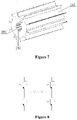
- the supporting capacitor has only positive and negative electrodes, as illustrated in Figure 8 , it can be implemented by one capacitor structure.
- the number of core 102 in the capacitor structure is not limited.
- the supporting capacitor can also be implemented by multiple capacitor structures connected in series and parallel. If the supporting capacitor has a midpoint, as illustrated in Figure 9 , it needs to be composed of at least two cores 102 to form the supporting capacitor.
- the supporting capacitor can be formed by connecting two capacitor structures in series, with a connection point of the two capacitor structures as the midpoint.
- the supporting capacitor may use only one capacitor structure, as long as it can simultaneously has three terminals of positive, negative and midpoint.
- an application of using of multiple such capacitor structures in series and parallel is not excluded, and there is no specific limitation here.
- a DC side of an internal DC-AC conversion circuit of the inverter is provided with DC bus capacitors (including C1 and C2 illustrated in the figure), and an AC side is provided with a filter capacitor (not shown).
- DC bus capacitors including C1 and C2 illustrated in the figure
- AC side is provided with a filter capacitor (not shown).
- left sides of the DC bus capacitors can be directly connected to corresponding photovoltaic strings (PV+ and PV- as illustrated in the figure), or at least one DC-DC conversion circuit can be used to connect to the corresponding photovoltaic strings, which is not specifically limited.
- At least one capacitor on the DC side is the capacitor structure described in any paragraph of the above embodiments, or at least one capacitor on the AC side is the capacitor structure described in any paragraph of the foregoing embodiments, or, both at least one capacitor on the DC side and at least one capacitor on the AC side are the capacitor structures described in any paragraph of the foregoing embodiments; there is no specific limitation here, as long as there is at least one capacitor inside is the capacitor structure described in any paragraph of the above-mentioned embodiments, which are all within the protection scope of the present disclosure.
- multiple capacitor structures can be connected in series and parallel to form the DC bus capacitor of the inverter.
- two capacitor structures are respectively used as a positive half-bus capacitor C1 and a negative half-bus capacitor C2 illustrated in Figure 10 , and are connected in series and parallel to form the DC bus capacitor.
- a midpoint of the two capacitor structures is taken as a midpoint of the DC bus.
- the capacitor structure includes at least two cores 102, for the DC side of the inverter, only one capacitor structure can be used, and at least one core 102 in an upper part of an inner part of the capacitor structure serves as the positive half-bus capacitor C1, each core 102 in a lower half of the inner part of the capacitor structure serves as the negative half-bus capacitor C2, as long as the capacitor structure can have three terminals of positive, negative and midpoint at the same time.
- the capacitor structure includes at least two cores 102, for the DC side of the inverter, only one capacitor structure can be used, and at least one core 102 in an upper part of an inner part of the capacitor structure serves as the positive half-bus capacitor C1, each core 102 in a lower half of the inner part of the capacitor structure serves as the negative half-bus capacitor C2, as long as the capacitor structure can have three terminals of positive, negative and midpoint at the same time.
- an application of multiple capacitor structures connected in series and parallel can be used. There is no specific limitation here.
- the AC side of the inverter such as a three-phase AC side
- three such capacitor structures can be used to form an AC side filter capacitor.
- a capacitor structure with three cores 102 can also be directly adopted, as long as each core 102 has implemented a connection relationship of the AC side filter capacitor inside the capacitor structure, all of which are within the protection scope of the present disclosure.
- the inverter may also be a bidirectional conversion device, which is not limited here, and depends on its specific application environment, and all are within the protection scope of the present disclosure.
- capacitors at a grid side, generator side, and DC bus can also be the capacitor structures described in the above embodiments, and a setting method of the capacitors is similar to the above content, which is not repeated one by one.
Landscapes
- Engineering & Computer Science (AREA)
- Power Engineering (AREA)
- Microelectronics & Electronic Packaging (AREA)
- Manufacturing & Machinery (AREA)
- Inverter Devices (AREA)
Applications Claiming Priority (1)
| Application Number | Priority Date | Filing Date | Title |
|---|---|---|---|
| CN202121110112.4U CN215377230U (zh) | 2021-05-21 | 2021-05-21 | 一种电容结构及功率变换器 |
Publications (2)
| Publication Number | Publication Date |
|---|---|
| EP4092703A1 true EP4092703A1 (de) | 2022-11-23 |
| EP4092703B1 EP4092703B1 (de) | 2026-04-01 |
Family
ID=79631235
Family Applications (1)
| Application Number | Title | Priority Date | Filing Date |
|---|---|---|---|
| EP22155528.7A Active EP4092703B1 (de) | 2021-05-21 | 2022-02-08 | Kondensatorstruktur und leistungswandler |
Country Status (3)
| Country | Link |
|---|---|
| US (1) | US12154725B2 (de) |
| EP (1) | EP4092703B1 (de) |
| CN (1) | CN215377230U (de) |
Citations (5)
| Publication number | Priority date | Publication date | Assignee | Title |
|---|---|---|---|---|
| US6762926B1 (en) * | 2003-03-24 | 2004-07-13 | Luxon Energy Devices Corporation | Supercapacitor with high energy density |
| US9378889B2 (en) * | 2012-07-27 | 2016-06-28 | RTR Enorgia, S.L. | Three-phase capacitor formed by two aligned cylinders with overpressure disconnection |
| WO2017150151A1 (ja) * | 2016-03-02 | 2017-09-08 | パナソニックIpマネジメント株式会社 | フィルムコンデンサ |
| US9865398B2 (en) * | 2013-06-23 | 2018-01-09 | Calem Passive Components Ltd | Capacitor and method of manufacture thereof |
| US20180330883A1 (en) * | 2016-02-19 | 2018-11-15 | Panasonic Intellectual Property Management Co., Ltd. | Capacitor and method for manufacturing the same |
Family Cites Families (9)
| Publication number | Priority date | Publication date | Assignee | Title |
|---|---|---|---|---|
| US3185907A (en) * | 1959-11-02 | 1965-05-25 | Welding Service Inc | Capacitor with metallic embedded plastic electrodes |
| US4264943A (en) * | 1979-03-07 | 1981-04-28 | Emhart Industries, Inc. | Hollow cored capacitor |
| US5940264A (en) * | 1996-10-04 | 1999-08-17 | Philips Electronics North America Corp | Electrolytic capacitor with heat sink and method of heat dissipation |
| SE526328C2 (sv) * | 2003-12-19 | 2005-08-23 | Abb Technology Ltd | Kraftkondensator |
| US7483257B2 (en) * | 2004-12-17 | 2009-01-27 | Cedric Scheidegger | HV capacitor and testing method |
| US7471499B2 (en) * | 2006-06-30 | 2008-12-30 | Electronic Concepts, Inc | Wound capacitor providing a thermal alert of a hot spot |
| JP5978463B2 (ja) * | 2011-11-17 | 2016-08-24 | パナソニックIpマネジメント株式会社 | 金属化フィルムコンデンサ |
| US8675336B2 (en) * | 2012-01-31 | 2014-03-18 | Electronics Concepts, Inc. | Multiple concentric wound film capacitors |
| US20170062131A1 (en) * | 2015-08-24 | 2017-03-02 | Aid Electronics Corporation | Method of Manufacturing Heat Transmission Structure of Capacitor |
-
2021
- 2021-05-21 CN CN202121110112.4U patent/CN215377230U/zh active Active
-
2022
- 2022-02-04 US US17/665,414 patent/US12154725B2/en active Active
- 2022-02-08 EP EP22155528.7A patent/EP4092703B1/de active Active
Patent Citations (5)
| Publication number | Priority date | Publication date | Assignee | Title |
|---|---|---|---|---|
| US6762926B1 (en) * | 2003-03-24 | 2004-07-13 | Luxon Energy Devices Corporation | Supercapacitor with high energy density |
| US9378889B2 (en) * | 2012-07-27 | 2016-06-28 | RTR Enorgia, S.L. | Three-phase capacitor formed by two aligned cylinders with overpressure disconnection |
| US9865398B2 (en) * | 2013-06-23 | 2018-01-09 | Calem Passive Components Ltd | Capacitor and method of manufacture thereof |
| US20180330883A1 (en) * | 2016-02-19 | 2018-11-15 | Panasonic Intellectual Property Management Co., Ltd. | Capacitor and method for manufacturing the same |
| WO2017150151A1 (ja) * | 2016-03-02 | 2017-09-08 | パナソニックIpマネジメント株式会社 | フィルムコンデンサ |
Also Published As
| Publication number | Publication date |
|---|---|
| CN215377230U (zh) | 2021-12-31 |
| US20220375687A1 (en) | 2022-11-24 |
| US12154725B2 (en) | 2024-11-26 |
| EP4092703B1 (de) | 2026-04-01 |
Similar Documents
| Publication | Publication Date | Title |
|---|---|---|
| EP3958373A1 (de) | Stapelbarer stromversorgungsschrank | |
| CN203800680U (zh) | 一种支持多组电池接入的大功率双向变流装置 | |
| EP4092703A1 (de) | Kondensatorstruktur und leistungswandler | |
| WO2023133501A3 (en) | Dispatchable decentralized scalable solar generation systems | |
| CN215186637U (zh) | 一种光伏板跳线接线结构 | |
| WO2020108412A1 (zh) | 功率模组以及电力电子设备 | |
| EP4092702A1 (de) | Kondensatorstruktur und leistungswandler | |
| CN221151619U (zh) | 驱动板组件及光伏系统 | |
| CN219458701U (zh) | 储能电源 | |
| CN209607828U (zh) | 锂电池储能模块及锂电池储能模组 | |
| CN208111588U (zh) | 一种储能模块电芯的摆置结构 | |
| CN212366853U (zh) | 储能系统 | |
| CN207947634U (zh) | 一种三相电充电电路结构 | |
| CN219760650U (zh) | 一种具有太阳能充电功能的储能变流器 | |
| CN216356515U (zh) | 功率模块装置及逆变器 | |
| CN211656040U (zh) | 功率模组以及电力电子设备 | |
| CN223583841U (zh) | 基于微处理器控制技术的大电流启动移动电源 | |
| CN205543150U (zh) | 一种电池模组的散热片结构 | |
| CN219477630U (zh) | 一种电池系统及储能系统 | |
| CN206041822U (zh) | 功率单元中的相单元、功率单元以及变频器 | |
| CN219696263U (zh) | 一种电解电容器盖板 | |
| CN218677411U (zh) | 一种电芯支撑散热壳体 | |
| CN221553086U (zh) | 一种户用混合逆变器 | |
| CN219436025U (zh) | 一种一体化软包电池组合结构 | |
| CN210092242U (zh) | 电池模组及电源装置 |
Legal Events
| Date | Code | Title | Description |
|---|---|---|---|
| PUAI | Public reference made under article 153(3) epc to a published international application that has entered the european phase |
Free format text: ORIGINAL CODE: 0009012 |
|
| STAA | Information on the status of an ep patent application or granted ep patent |
Free format text: STATUS: THE APPLICATION HAS BEEN PUBLISHED |
|
| AK | Designated contracting states |
Kind code of ref document: A1 Designated state(s): AL AT BE BG CH CY CZ DE DK EE ES FI FR GB GR HR HU IE IS IT LI LT LU LV MC MK MT NL NO PL PT RO RS SE SI SK SM TR |
|
| STAA | Information on the status of an ep patent application or granted ep patent |
Free format text: STATUS: REQUEST FOR EXAMINATION WAS MADE |
|
| 17P | Request for examination filed |
Effective date: 20230322 |
|
| RBV | Designated contracting states (corrected) |
Designated state(s): AL AT BE BG CH CY CZ DE DK EE ES FI FR GB GR HR HU IE IS IT LI LT LU LV MC MK MT NL NO PL PT RO RS SE SI SK SM TR |
|
| GRAP | Despatch of communication of intention to grant a patent |
Free format text: ORIGINAL CODE: EPIDOSNIGR1 |
|
| STAA | Information on the status of an ep patent application or granted ep patent |
Free format text: STATUS: GRANT OF PATENT IS INTENDED |
|
| INTG | Intention to grant announced |
Effective date: 20251120 |
|
| GRAS | Grant fee paid |
Free format text: ORIGINAL CODE: EPIDOSNIGR3 |
|
| GRAA | (expected) grant |
Free format text: ORIGINAL CODE: 0009210 |
|
| STAA | Information on the status of an ep patent application or granted ep patent |
Free format text: STATUS: THE PATENT HAS BEEN GRANTED |
|
| AK | Designated contracting states |
Kind code of ref document: B1 Designated state(s): AL AT BE BG CH CY CZ DE DK EE ES FI FR GB GR HR HU IE IS IT LI LT LU LV MC MK MT NL NO PL PT RO RS SE SI SK SM TR |
|
| REG | Reference to a national code |
Ref country code: CH Ref legal event code: F10 Free format text: ST27 STATUS EVENT CODE: U-0-0-F10-F00 (AS PROVIDED BY THE NATIONAL OFFICE) Effective date: 20260401 Ref country code: GB Ref legal event code: FG4D |
|
| REG | Reference to a national code |
Ref country code: IE Ref legal event code: FG4D |
|
| REG | Reference to a national code |
Ref country code: DE Ref legal event code: R096 Ref document number: 602022033264 Country of ref document: DE |