EP4092708A1 - Vakuumschaltröhre - Google Patents
Vakuumschaltröhre Download PDFInfo
- Publication number
- EP4092708A1 EP4092708A1 EP21175316.5A EP21175316A EP4092708A1 EP 4092708 A1 EP4092708 A1 EP 4092708A1 EP 21175316 A EP21175316 A EP 21175316A EP 4092708 A1 EP4092708 A1 EP 4092708A1
- Authority
- EP
- European Patent Office
- Prior art keywords
- contact piece
- contact
- vacuum interrupter
- carrier
- piece
- Prior art date
- Legal status (The legal status is an assumption and is not a legal conclusion. Google has not performed a legal analysis and makes no representation as to the accuracy of the status listed.)
- Pending
Links
Images

Classifications
-
- H—ELECTRICITY
- H01—ELECTRIC ELEMENTS
- H01H—ELECTRIC SWITCHES; RELAYS; SELECTORS; EMERGENCY PROTECTIVE DEVICES
- H01H33/00—High-tension or heavy-current switches with arc-extinguishing or arc-preventing means
- H01H33/60—Switches wherein the means for extinguishing or preventing the arc do not include separate means for obtaining or increasing flow of arc-extinguishing fluid
- H01H33/66—Vacuum switches
- H01H33/664—Contacts; Arc-extinguishing means, e.g. arcing rings
- H01H33/6643—Contacts; Arc-extinguishing means, e.g. arcing rings having disc-shaped contacts subdivided in petal-like segments, e.g. by helical grooves
-
- H—ELECTRICITY
- H01—ELECTRIC ELEMENTS
- H01H—ELECTRIC SWITCHES; RELAYS; SELECTORS; EMERGENCY PROTECTIVE DEVICES
- H01H1/00—Contacts
- H01H1/02—Contacts characterised by the material thereof
- H01H1/0203—Contacts characterised by the material thereof specially adapted for vacuum switches
-
- H—ELECTRICITY
- H01—ELECTRIC ELEMENTS
- H01H—ELECTRIC SWITCHES; RELAYS; SELECTORS; EMERGENCY PROTECTIVE DEVICES
- H01H1/00—Contacts
- H01H1/02—Contacts characterised by the material thereof
- H01H1/0203—Contacts characterised by the material thereof specially adapted for vacuum switches
- H01H1/0206—Contacts characterised by the material thereof specially adapted for vacuum switches containing as major components Cu and Cr
-
- H—ELECTRICITY
- H01—ELECTRIC ELEMENTS
- H01H—ELECTRIC SWITCHES; RELAYS; SELECTORS; EMERGENCY PROTECTIVE DEVICES
- H01H1/00—Contacts
- H01H1/06—Contacts characterised by the shape or structure of the contact-making surface, e.g. grooved
Definitions
- the present invention relates a vacuum interrupter and to a method of manufacturing a vacuum interrupter.
- Vacuum interrupters are required to have contacts that can operate with a high short circuit switching performance and resist becoming welded together.
- a vacuum interrupter comprising:
- the first contact carrier is a fixed contact carrier and the second contact carrier is a movable contact carrier.
- the vacuum interrupter is configured to move the second contact carrier to bring the first contact piece and the second contact piece into contact with one another.
- the material of the first contact piece is a first alloy of CuCr and the material of the second contact piece is a second alloy of CuCr.
- the material of the first contact piece is CuCr10 and the material of the second contact piece is CuCr50.
- the material of the first contact piece is CuCr25 and the material of the second contact piece is CuCr35.
- the material of the first contact piece is a first alloy of WCAg and the material of the second contact piece is a second alloy of WCAg.
- the material of the first contact piece is WCAg40 and the material of the second contact piece is WCAg20.
- the material of the first contact piece is CuCr and the material of the second contact piece is CuCr with a content of 0.1% to 5% of at least one material comprising Fe, Al, Cr, V, Nb, Ta, Hf, Sn, Zr or Si.
- the at least one material comprises an oxide, nitride or boride of Fe, Al, Cr, V, Nb, Ta, Hf, Sn, Zr or Si.
- the material of the first contact piece is CuCr and the material of the second contact piece is WCu or MoCu.
- the material of the first contact piece comprises one of W, CuCr, CuBi, WCu, MoCu, WCAg and the material of the second contact piece comprises one of W, CuCr, CuBi, WCu, MoCu, WCAg.
- a size of the first contact piece is different to a size of the second contact piece.
- a diameter of the first contact piece is less than a diameter of the second contact piece.
- the vacuum interrupter comprises an upper lid, and the first contact carrier is fixedly connected to the upper lid.
- the upper lid Prior to the first contact carrier being fixedly connected to the upper lid the upper lid comprises a hole with a diameter greater than a diameter of the first contact piece and greater than a diameter of at least a portion of the first contact carrier adjacent to the first contact piece.
- a vacuum interrupter comprising:
- an upper lid comprises a hole with a diameter greater than a diameter of the first contact piece and greater than a diameter of at least a portion of the first contact carrier adjacent to the first contact piece, and wherein method comprises inserting the first contact piece and the at least portion of the first contact carrier through the hole and fixedly connecting the first contact carrier to the upper lid.
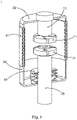
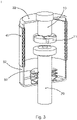
- Figures 1-3 relate to a vacuum interrupter and to a method of manufacturing a vacuum interrupter.
- a vacuum interrupter 1 comprises a first contact carrier 10, a first contact piece 11, a second contact carrier 20, and a second contact piece 21.
- the first contact piece is connected to the first contact carrier.
- the second contact piece is connected to the second contact carrier.
- a shape of the first contact piece is different to a shape of the second contact piece.
- a material of the first contact piece is different to a material of the second contact piece.
- the first contact carrier is a fixed contact carrier and the second contact carrier is a movable contact carrier, and in the activated state the vacuum interrupter is configured to move the second contact carrier to bring the first contact piece and the second contact piece into contact with one another.
- the material of the first contact piece is a first alloy of CuCr and the material of the second contact piece is a second alloy of CuCr.
- the material of the first contact piece is CuCr10 and the material of the second contact piece is CuCr50.
- the material of the first contact piece is CuCr25 and the material of the second contact piece is CuCr35.
- the material of the first contact piece is a first alloy of WCAg and the material of the second contact piece is a second alloy of WCAg.
- the material of the first contact piece is WCAg40 and the material of the second contact piece is WCAg20.
- the material of the first contact piece is CuCr and the material of the second contact piece is CuCr with a content of 0.1 % to 5% of at least one material comprising Fe, Al, Cr, V, Nb, Ta, Hf, Sn, Zr or Si.
- the at least one material comprises an oxide, nitride or boride of Fe, Al, Cr, V, Nb, Ta, Hf, Sn, Zr or Si.
- the material of the first contact piece is CuCr and the material of the second contact piece is WCu.
- the material of the first contact piece is CuCr and the material of the second contact piece is MoCu.
- the material of the first contact piece comprises one of W, CuCr, CuBi, WCu, MoCu, WCAg and the material of the second contact piece comprises one of W, CuCr, CuBi, WCu, MoCu, WCAg.
- a size of the first contact piece is different to a size of the second contact piece.
- a diameter of the first contact piece is less than a diameter of the second contact piece.
- the vacuum interrupter comprises an upper lid 30.
- the first contact carrier is fixedly connected to the upper lid.
- the upper lid Prior to the first contact carrier being fixedly connected to the upper lid the upper lid comprises a hole with a diameter greater than a diameter of the first contact piece and greater than a diameter of at least a portion of the first contact carrier adjacent to the first contact piece.
- a method of manufacturing a vacuum interrupter 1 comprises:
- the first contact carrier is a fixed contact carrier and the second contact carrier is a movable contact carrier, and in the activated state the vacuum interrupter is configured to move the second contact carrier to bring the first contact piece and the second contact piece into contact with one another.
- the material of the first contact piece is a first alloy of CuCr and the material of the second contact piece is a second alloy of CuCr.
- the material of the first contact piece is CuCr10 and the material of the second contact piece is CuCr50; or wherein the material of the first contact piece is CuCr25 and the material of the second contact piece is CuCr35.
- the material of the first contact piece is a first alloy of WCAg and the material of the second contact piece is a second alloy of WCAg.
- the material of the first contact piece is WCAg40 and the material of the second contact piece is WCAg20.
- the material of the first contact piece is CuCr and the material of the second contact piece is CuCr with a content of 0.1% to 5% of at least one material comprising Fe, Al, Cr, V, Nb, Ta, Hf, Sn, Zr or Si.
- the at least one material comprises an oxide, nitride or boride of Fe, Al, Cr, V, Nb, Ta, Hf, Sn, Zr or Si.
- the material of the first contact piece is CuCr and the material of the second contact piece is WCu or MoCu.
- the material of the first contact piece comprises one of W, CuCr, CuBi, WCu, MoCu, WCAg and the material of the second contact piece comprises one of W, CuCr, CuBi, WCu, MoCu, WCAg.
- a size of the first contact piece is different to a size of the second contact piece.
- a diameter of the first contact piece is less than a diameter of the second contact piece.
- an upper lid 30 of the vacuum interrupter comprises a hole with a diameter greater than a diameter of the first contact piece and greater than a diameter of at least a portion of the first contact carrier adjacent to the first contact piece.
- the method then comprise inserting the first contact piece and the at least portion of the first contact carrier through the hole and fixedly connecting the first contact carrier to the upper lid.
- CuCr contacts can be used for circuit breaker vacuum interrupters, representing a good compromise for low ohmic resistance, relatively low chopping current, good short-circuit switching performance, medium tendency to contact welding, low wear and reasonable production costs. They also determined that WCu contacts can be used for load break switches, representing a good compromise for low ohmic resistance, relatively low chopping current, good short-circuit switching performance as long as the current is below a certain limit, low tendency to contact welding, low wear and reasonable production costs. They also determined that WCAg contacts can be used for contactors for its very low chopping current, its low tendency for the generation of surge voltages and its low tendency to contact welding; however it has limitations in interrupting high short-circuit currents and it has relatively high costs.
- Figure 1 shows a representation of a vacuum interrupter 1. It mainly consists of a fixed contact carrier 10, generally made of copper, a fixed or first contact piece 11, a movable contact carrier 20, generally made of copper, a movable or second contact piece 21, an upper lid 30, for example made of stainless steel, an insulator 40, for example made of ceramic or ceramics, a lower lid 50, for example made of stainless steel and a bellows 60, for example made of stainless steel.
- a fixed contact carrier 10 generally made of copper
- a fixed or first contact piece 11
- a movable contact carrier 20 generally made of copper
- a movable or second contact piece 21 an upper lid 30, for example made of stainless steel
- an insulator 40 for example made of ceramic or ceramics
- a lower lid 50 for example made of stainless steel
- a bellows 60 for example made of stainless steel.
- the contact piece materials can comprise W, CuCr, CuBi, WCu, MoCu, WCAg with different material shares, e.g. CuCr25, CuCr35, CuCr50 and made via different production methods, like sintering from a powder containing all components or first sintering the component with the high resistance against wear and welding - like Cr, W or WC - and then infiltrating it with the component that has a low ohmic resistance - like Cu or Ag.
- the contact pieces can also be CuCr alloyed with additives like oxides, nitrides or borides of Fe, Al, Cr, V, Nb, Ta, Hf, Sn, Zr or Si with a relative content of about 0.1% to 5% acting as dispersoids for increasing the hardness and the welding resistance are being considered.
- the fixed contact piece 11 and the movable contact piece 21 are made from different materials.
- the inventors established that specific advantages of different materials could be enabled by using the two contact pieces made from these different contact piece materials in one vacuum interrupter. In this way they found combinations where the specific advantages of each material can be combined.
- the material of the first contact piece is CuCr10, while the material of the second contact piece is CuCr50.
- a vacuum interrupter is provided that has a higher short circuit switching performance and a higher welding resistance than a vacuum interrupter with two contacts made from CuCr10 and at the same time having a vacuum interrupter with a lower ohmic resistance than a vacuum interrupter with two contacts made from CuCr50.
- the material of the first contact piece is CuCr
- the material of the second contact piece is CuCr with a content of about 1% of additives acting as dispersoids to increase the hardness and welding resistance of the contact piece.
- a vacuum interrupter is provided that has a higher short circuit switching performance and welding resistance than a vacuum interrupter with two contacts made from CuCr and at the same time having a vacuum interrupter with lower costs compared to a vacuum interrupter with two contact pieces made from CuCr with an additive.
- the material of the first contact piece is CuCr
- the material of the second contact piece is WCu or MoCu.
- the short circuit switching performance is extended to higher currents compared to a vacuum interrupter with two contacts made from WCu or MoCu and at the same time having a vacuum interrupter with a higher welding resistance and a lower chopping current compared to a vacuum interrupter with two contacts made of CuCr.
- a combination of certain contact piece materials can however also result in unwanted results.
- the combination of Cu in one contact piece with Ag in the other contact piece can result in easily welded contacts because of the property of Cu and Ag to establish an eutectic mixture. These combinations are therefore to be avoided.
- Figure 2 shows an advantageous embodiment where one contact piece, here the fixed contact piece, has a different size than the other contact piece, beside of that the two contact pieces consist of different contact piece materials.
- the contacts have different sizes and/or different shapes, they can have the same material. However, further advantages are provided when the materials of the contacts are different.
- an advantage of this embodiment is a reduction of the production costs.
- Another advantage of the embodiment shown in figure 2 is that the diameter of the contact piece is not larger than the corresponding diameter in the upper lid 30, i.e. the fixed contact carrier 10 and the fixed contact piece 11 can be pre-assembled and then inserted as one piece into the upper lid before an OSB (one shot brazing) process. This simplifies the production process and reduces the risk that the contact piece 11 is misaligned or even falls off during the OSB process.
- Figure 3 shows an advantageous embodiment where the two contact pieces have different shapes beside of that the two contact pieces consist of different contact piece materials; again as detailed above, the contacts can be of the same material when they have different shapes, but further advantages are provided when the materials are different. Especially for lower short-circuit interruption ratings, it is sufficient to install means for the generation of a magnetic field in one of the two contacts. The advantage is a reduction of the production costs.
- the new vacuum interrupter uses two contact pieces of different contact piece materials in one vacuum interrupter with the target that the specific advantages of each material can be combined in one vacuum interrupter and that better compromises for the overall performance of a vacuum interrupter can be achieved.
Landscapes
- High-Tension Arc-Extinguishing Switches Without Spraying Means (AREA)
Priority Applications (4)
| Application Number | Priority Date | Filing Date | Title |
|---|---|---|---|
| EP21175316.5A EP4092708A1 (de) | 2021-05-21 | 2021-05-21 | Vakuumschaltröhre |
| PCT/EP2022/062891 WO2022243148A1 (en) | 2021-05-21 | 2022-05-12 | Vacuum interrupter |
| CN202280035708.3A CN117321719A (zh) | 2021-05-21 | 2022-05-12 | 真空断续器 |
| US18/516,202 US20240087822A1 (en) | 2021-05-21 | 2023-11-21 | Vacuum Interrupter |
Applications Claiming Priority (1)
| Application Number | Priority Date | Filing Date | Title |
|---|---|---|---|
| EP21175316.5A EP4092708A1 (de) | 2021-05-21 | 2021-05-21 | Vakuumschaltröhre |
Publications (1)
| Publication Number | Publication Date |
|---|---|
| EP4092708A1 true EP4092708A1 (de) | 2022-11-23 |
Family
ID=76059767
Family Applications (1)
| Application Number | Title | Priority Date | Filing Date |
|---|---|---|---|
| EP21175316.5A Pending EP4092708A1 (de) | 2021-05-21 | 2021-05-21 | Vakuumschaltröhre |
Country Status (4)
| Country | Link |
|---|---|
| US (1) | US20240087822A1 (de) |
| EP (1) | EP4092708A1 (de) |
| CN (1) | CN117321719A (de) |
| WO (1) | WO2022243148A1 (de) |
Cited By (2)
| Publication number | Priority date | Publication date | Assignee | Title |
|---|---|---|---|---|
| CN119876876A (zh) * | 2025-01-20 | 2025-04-25 | 西安交通大学 | 一种真空断路器用铜铬触头材料表面合金薄膜及其制备方法 |
| EP4567850A1 (de) * | 2023-12-04 | 2025-06-11 | ABB Schweiz AG | Kontaktanordnung für leistungsschalter |
Citations (4)
| Publication number | Priority date | Publication date | Assignee | Title |
|---|---|---|---|---|
| GB1121385A (en) * | 1966-05-27 | 1968-07-24 | English Electric Co Ltd | Improvements in or relating to contacts for vacuum interrupters |
| KR20140027806A (ko) * | 2012-08-27 | 2014-03-07 | 엘에스산전 주식회사 | 진공 인터럽터의 접점 및 그 제조방법 |
| CN104966650A (zh) * | 2015-05-28 | 2015-10-07 | 北京航空航天大学 | 真空灭弧室及其触头结构 |
| US20170250040A1 (en) * | 2014-12-01 | 2017-08-31 | Mitsubishi Electric Corporation | Circuit closer and circuit closing system |
Family Cites Families (11)
| Publication number | Priority date | Publication date | Assignee | Title |
|---|---|---|---|---|
| US4661666A (en) * | 1985-05-28 | 1987-04-28 | Kabushiki Kaisha Meidensha | Vacuum interrupter |
| JP3825275B2 (ja) * | 2001-04-13 | 2006-09-27 | 株式会社日立製作所 | 電気接点部材とその製法 |
| JP2006032036A (ja) * | 2004-07-14 | 2006-02-02 | Toshiba Corp | 真空バルブ用接点材料 |
| CN101617376B (zh) * | 2006-12-15 | 2011-08-24 | Abb研究有限公司 | 触点元件 |
| EP2469562A1 (de) * | 2010-12-22 | 2012-06-27 | ABB Technology AG | Unterbrechereinsatz für einen Schalter |
| CN102938337B (zh) * | 2012-10-22 | 2015-06-10 | 西安建筑科技大学 | 一种梯度触头材料的生产工艺 |
| US9330867B2 (en) * | 2014-05-13 | 2016-05-03 | Eaton Corporation | Vacuum switching apparatus, and electrode extension assembly and associated assembly method therefor |
| DE102015203693A1 (de) * | 2015-03-02 | 2016-09-08 | Siemens Aktiengesellschaft | Verfahren zum Herstellen von Vakuumschaltkontakten |
| KR101992736B1 (ko) * | 2015-04-22 | 2019-06-26 | 엘에스산전 주식회사 | 진공 인터럽터의 접점부 |
| WO2019155655A1 (ja) * | 2018-02-06 | 2019-08-15 | 三菱電機株式会社 | 電気接点およびそれを用いた真空バルブ |
| CN112756915B (zh) * | 2020-12-29 | 2022-05-27 | 陕西斯瑞新材料股份有限公司 | 一种开槽型触头产品的加工方法 |
-
2021
- 2021-05-21 EP EP21175316.5A patent/EP4092708A1/de active Pending
-
2022
- 2022-05-12 WO PCT/EP2022/062891 patent/WO2022243148A1/en not_active Ceased
- 2022-05-12 CN CN202280035708.3A patent/CN117321719A/zh active Pending
-
2023
- 2023-11-21 US US18/516,202 patent/US20240087822A1/en active Pending
Patent Citations (4)
| Publication number | Priority date | Publication date | Assignee | Title |
|---|---|---|---|---|
| GB1121385A (en) * | 1966-05-27 | 1968-07-24 | English Electric Co Ltd | Improvements in or relating to contacts for vacuum interrupters |
| KR20140027806A (ko) * | 2012-08-27 | 2014-03-07 | 엘에스산전 주식회사 | 진공 인터럽터의 접점 및 그 제조방법 |
| US20170250040A1 (en) * | 2014-12-01 | 2017-08-31 | Mitsubishi Electric Corporation | Circuit closer and circuit closing system |
| CN104966650A (zh) * | 2015-05-28 | 2015-10-07 | 北京航空航天大学 | 真空灭弧室及其触头结构 |
Non-Patent Citations (3)
| Title |
|---|
| DATABASE INSPEC [online] THE INSTITUTION OF ELECTRICAL ENGINEERS, STEVENAGE, GB; 22 September 2000 (2000-09-22), TEMBORIUS S ET AL: "Switching behavior of different contact materials for vacuum interrupters under load switching conditions", Database accession no. 6852531 * |
| PROCEEDINGS OF 19TH INTERNATIONAL SYMPOSIUM ON DISCHARGE AND ELECTRICAL INSULATION IN VACUUM, vol. 2, 6 August 2002 (2002-08-06), Proceedings ISDEIV. 19th International Symposium on Discharges and Electrical Insulation in Vacuum (Cat. No.00CH37041) IEEE Piscataway, NJ, USA, pages 519, ISBN: 0-7803-5791-4, DOI: 10.1109/DEIV.2000.879041 * |
| SLADE P G ET AL: "THE UNUSUAL ELECTRICAL EROSION OF HIGH TUNGSTEN CONTENT, TUNGSTEN COPPER CONTACTS SWITCHING LOAD CURRENT IN VACUUM", IEEE TRANSACTIONS ON COMPONENTS AND PACKAGING TECHNOLOGIES,, vol. 24, no. 3, 1 September 2001 (2001-09-01), pages 320 - 330, XP001110731, ISSN: 1521-3331, DOI: 10.1109/6144.946474 * |
Cited By (2)
| Publication number | Priority date | Publication date | Assignee | Title |
|---|---|---|---|---|
| EP4567850A1 (de) * | 2023-12-04 | 2025-06-11 | ABB Schweiz AG | Kontaktanordnung für leistungsschalter |
| CN119876876A (zh) * | 2025-01-20 | 2025-04-25 | 西安交通大学 | 一种真空断路器用铜铬触头材料表面合金薄膜及其制备方法 |
Also Published As
| Publication number | Publication date |
|---|---|
| US20240087822A1 (en) | 2024-03-14 |
| CN117321719A (zh) | 2023-12-29 |
| WO2022243148A1 (en) | 2022-11-24 |
Similar Documents
| Publication | Publication Date | Title |
|---|---|---|
| Slade | Advances in material development for high power, vacuum interrupter contacts | |
| EP0153635B2 (de) | Kontaktelektrodenmaterial für Vakuumschalter und Herstellungsverfahren für dasselbe | |
| US20240087822A1 (en) | Vacuum Interrupter | |
| EP0119563B1 (de) | Vakuumschalter und Verfahren zu dessen Herstellung | |
| WO2011162398A1 (ja) | 真空遮断器用電極材料の製造方法、真空遮断器用電極材料及び真空遮断器用電極 | |
| GB2024258A (en) | Contact for vacuum interrupter | |
| US3008022A (en) | Contact structure for a vacuum-type circuit interrupter | |
| Slade | Contact materials for vacuum interrupters | |
| EP0076659B1 (de) | Vakuumschalter | |
| JP2766441B2 (ja) | 真空バルブ用接点材料 | |
| JP2011108380A (ja) | 真空バルブ用電気接点およびそれを用いた真空遮断器 | |
| US4299889A (en) | Contact for vacuum interrupter | |
| EP4276864A1 (de) | Vakuumschaltröhre | |
| KR100199429B1 (ko) | 진공 차단기용 접점 재료 및 그 제조방법 | |
| JPH10255603A (ja) | 真空バルブ用接点材料 | |
| EP4456108A1 (de) | Kupferverbundwerkstoff | |
| JP4988489B2 (ja) | 電気接点 | |
| EP0178796B1 (de) | Herstellung von Vakuumschalterkontakten | |
| JP2839570B2 (ja) | 真空バルブ | |
| US6326573B1 (en) | Vacuum switching device | |
| JPH1083745A (ja) | 真空バルブ用接点材料及び電極材料 | |
| EP4567850A1 (de) | Kontaktanordnung für leistungsschalter | |
| JPH1139973A (ja) | 真空バルブ用接点材料 | |
| JP3443516B2 (ja) | 真空バルブ用接点材料の製造方法 | |
| JPH061655B2 (ja) | 真空しや断器 |
Legal Events
| Date | Code | Title | Description |
|---|---|---|---|
| PUAI | Public reference made under article 153(3) epc to a published international application that has entered the european phase |
Free format text: ORIGINAL CODE: 0009012 |
|
| STAA | Information on the status of an ep patent application or granted ep patent |
Free format text: STATUS: THE APPLICATION HAS BEEN PUBLISHED |
|
| AK | Designated contracting states |
Kind code of ref document: A1 Designated state(s): AL AT BE BG CH CY CZ DE DK EE ES FI FR GB GR HR HU IE IS IT LI LT LU LV MC MK MT NL NO PL PT RO RS SE SI SK SM TR |
|
| STAA | Information on the status of an ep patent application or granted ep patent |
Free format text: STATUS: REQUEST FOR EXAMINATION WAS MADE |
|
| 17P | Request for examination filed |
Effective date: 20230418 |
|
| RBV | Designated contracting states (corrected) |
Designated state(s): AL AT BE BG CH CY CZ DE DK EE ES FI FR GB GR HR HU IE IS IT LI LT LU LV MC MK MT NL NO PL PT RO RS SE SI SK SM TR |
|
| STAA | Information on the status of an ep patent application or granted ep patent |
Free format text: STATUS: EXAMINATION IS IN PROGRESS |
|
| 17Q | First examination report despatched |
Effective date: 20241211 |