EP4092835B1 - Connecteur enfichable électrique, agencement de connecteur enfichable électrique et connecteur enfichable électrique - Google Patents
Connecteur enfichable électrique, agencement de connecteur enfichable électrique et connecteur enfichable électrique Download PDFInfo
- Publication number
- EP4092835B1 EP4092835B1 EP21174634.2A EP21174634A EP4092835B1 EP 4092835 B1 EP4092835 B1 EP 4092835B1 EP 21174634 A EP21174634 A EP 21174634A EP 4092835 B1 EP4092835 B1 EP 4092835B1
- Authority
- EP
- European Patent Office
- Prior art keywords
- compression sleeve
- stop element
- plug connector
- longitudinal axis
- electrical plug
- Prior art date
- Legal status (The legal status is an assumption and is not a legal conclusion. Google has not performed a legal analysis and makes no representation as to the accuracy of the status listed.)
- Active
Links
Images


Classifications
-
- H—ELECTRICITY
- H01—ELECTRIC ELEMENTS
- H01R—ELECTRICALLY-CONDUCTIVE CONNECTIONS; STRUCTURAL ASSOCIATIONS OF A PLURALITY OF MUTUALLY-INSULATED ELECTRICAL CONNECTING ELEMENTS; COUPLING DEVICES; CURRENT COLLECTORS
- H01R24/00—Two-part coupling devices, or either of their cooperating parts, characterised by their overall structure
- H01R24/38—Two-part coupling devices, or either of their cooperating parts, characterised by their overall structure having concentrically or coaxially arranged contacts
- H01R24/40—Two-part coupling devices, or either of their cooperating parts, characterised by their overall structure having concentrically or coaxially arranged contacts specially adapted for high frequency
- H01R24/56—Two-part coupling devices, or either of their cooperating parts, characterised by their overall structure having concentrically or coaxially arranged contacts specially adapted for high frequency specially adapted to a specific shape of cables, e.g. corrugated cables, twisted pair cables, cables with two screens or hollow cables
- H01R24/564—Corrugated cables
-
- H—ELECTRICITY
- H01—ELECTRIC ELEMENTS
- H01R—ELECTRICALLY-CONDUCTIVE CONNECTIONS; STRUCTURAL ASSOCIATIONS OF A PLURALITY OF MUTUALLY-INSULATED ELECTRICAL CONNECTING ELEMENTS; COUPLING DEVICES; CURRENT COLLECTORS
- H01R13/00—Details of coupling devices of the kinds covered by groups H01R12/70 or H01R24/00 - H01R33/00
- H01R13/646—Details of coupling devices of the kinds covered by groups H01R12/70 or H01R24/00 - H01R33/00 specially adapted for high-frequency, e.g. structures providing an impedance match or phase match
- H01R13/6473—Impedance matching
-
- H—ELECTRICITY
- H01—ELECTRIC ELEMENTS
- H01R—ELECTRICALLY-CONDUCTIVE CONNECTIONS; STRUCTURAL ASSOCIATIONS OF A PLURALITY OF MUTUALLY-INSULATED ELECTRICAL CONNECTING ELEMENTS; COUPLING DEVICES; CURRENT COLLECTORS
- H01R13/00—Details of coupling devices of the kinds covered by groups H01R12/70 or H01R24/00 - H01R33/00
- H01R13/62—Means for facilitating engagement or disengagement of coupling parts or for holding them in engagement
- H01R13/639—Additional means for holding or locking coupling parts together, after engagement, e.g. separate keylock, retainer strap
-
- H—ELECTRICITY
- H01—ELECTRIC ELEMENTS
- H01R—ELECTRICALLY-CONDUCTIVE CONNECTIONS; STRUCTURAL ASSOCIATIONS OF A PLURALITY OF MUTUALLY-INSULATED ELECTRICAL CONNECTING ELEMENTS; COUPLING DEVICES; CURRENT COLLECTORS
- H01R9/00—Structural associations of a plurality of mutually-insulated electrical connecting elements, e.g. terminal strips or terminal blocks; Terminals or binding posts mounted upon a base or in a case; Bases therefor
- H01R9/03—Connectors arranged to contact a plurality of the conductors of a multiconductor cable, e.g. tapping connections
- H01R9/05—Connectors arranged to contact a plurality of the conductors of a multiconductor cable, e.g. tapping connections for coaxial cables
- H01R9/0521—Connection to outer conductor by action of a nut
-
- H—ELECTRICITY
- H01—ELECTRIC ELEMENTS
- H01R—ELECTRICALLY-CONDUCTIVE CONNECTIONS; STRUCTURAL ASSOCIATIONS OF A PLURALITY OF MUTUALLY-INSULATED ELECTRICAL CONNECTING ELEMENTS; COUPLING DEVICES; CURRENT COLLECTORS
- H01R9/00—Structural associations of a plurality of mutually-insulated electrical connecting elements, e.g. terminal strips or terminal blocks; Terminals or binding posts mounted upon a base or in a case; Bases therefor
- H01R9/03—Connectors arranged to contact a plurality of the conductors of a multiconductor cable, e.g. tapping connections
- H01R9/05—Connectors arranged to contact a plurality of the conductors of a multiconductor cable, e.g. tapping connections for coaxial cables
- H01R9/0524—Connection to outer conductor by action of a clamping member, e.g. screw fastening means
-
- H—ELECTRICITY
- H01—ELECTRIC ELEMENTS
- H01R—ELECTRICALLY-CONDUCTIVE CONNECTIONS; STRUCTURAL ASSOCIATIONS OF A PLURALITY OF MUTUALLY-INSULATED ELECTRICAL CONNECTING ELEMENTS; COUPLING DEVICES; CURRENT COLLECTORS
- H01R2103/00—Two poles
Definitions
- the present invention relates to an electrical connector having the features of patent claim 1.
- the present invention also relates to an electrical connector assembly having the features of patent claim 14.
- the present invention relates to an electrical connector having the features of patent claim 15.
- the cable is connected to the connector on site using a suitable mechanical, hydraulic, pneumatic or electrical tool, which presses the cable to the connector on the inner and outer conductor side.
- a suitable mechanical, hydraulic, pneumatic or electrical tool which presses the cable to the connector on the inner and outer conductor side.
- the axial end of the rigid cable inner conductor is pressed into a socket-shaped inner conductor contact element of the connector and the axial end of the cable outer conductor tube is pressed between a stop element and a compression sleeve of the connector.
- a connector is also referred to as a compression connector due to the compression of cable and connector.
- the cable and the connector can also be screwed together.
- the stop element as a component of the connector outer conductor is made of a metallic material, the compression sleeve can be made of a metallic or non-metallic material.
- the inner conductor contact is essentially a radial contact, while the outer conductor contact is preferably a contact with an axial and a radial component.
- the cable which has an outer conductor with a thread-shaped outer surface, is screwed into the compression sleeve of the connector, which for this purpose has a thread-shaped outer surface of the Has outer cable conductor corresponding thread-shaped inner surface.
- the thread turn on the outer surface of the outer cable conductor and correspondingly on the inner surface of the compression sleeve each have a specific pitch angle.
- the last turn of the thread turn at the axial end of the thread has a variable axial angle due to the pitch angle along its 360° extent Distance to the opposite end face of the stop element.
- the axial end of the outer cable conductor clamped between the stop element and the compression sleeve is thus subjected to a different clamping force along the press-in zone extending over 360°.
- the contact force between the outer cable conductor and the stop element is therefore not constant along the press-in zone.
- the axial end of the outer cable conductor can be more loosely clamped in the angular segment of the contacting area in which the contact pressure is lower due to the pitch angle of the thread and thus partially protrude into the elastic area of the dielectric, which is typically made of foamed polyethylene.
- the transmission characteristic of the high-frequency signal path thus becomes more capacitive at this point.
- Such a Impurities in the impedance profile of the high-frequency signal path disadvantageously lead to reflections of the high-frequency signal.
- the present invention is based on the object of specifying an electrical plug connector for a "corrugated cable” which has optimized electrical transmission properties, in particular optimized high-frequency transmission properties.
- the finding/idea on which the present invention is based is to shape the stop surface of the stop element, against which the axial end of the cable outer conductor is pressed with the compression sleeve in the assembled state of the connector and the cable, in such a way that the foremost turn of the in the internal thread formed in the compression sleeve runs as parallel as possible to the stop surface of the stop element over as large an angular segment as possible of the sleeve-shaped circumference.
- a longitudinal axis of the compression sleeve is tilted by a tilting angle at least in the axial end area of the compression sleeve relative to a longitudinal axis of the stop element at least in the axial end area of the stop element.
- a normal vector of a plane spanned by an edge between an end face and an inner lateral surface of the stop element is rotated by an orientation angle relative to the longitudinal axis of the compression sleeve.
- the edge between the end face and the inner lateral surface of the stop element runs in a helical shape in the longitudinal axis direction of the plug connector.
- the stop element and the compression sleeve are each a preferably sleeve-shaped body.
- the axial end area of the compression sleeve and the axial end area of the stop element are each preferably a sleeve-shaped body.
- a longitudinal axis of the stop element, the compression sleeve and the axial end area of the stop element or the compression sleeve therefore runs along the center of rotation of the respective element or the respective end area.
- a normal vector of a plane or any other surface is to be understood here and in the following as a vector which has an alignment perpendicular to the extension of the plane or surface.
- the cable outer conductor is optimally clamped between the stop element and the compression sleeve at only a single point on the circumference, and thus an optimal contact pressure is achieved.
- the optimal clamping of the cable outer conductor in the connector outer conductor and thus the formation of an optimal contact pressure between the cable outer conductor and the connector outer conductor is advantageous over a larger angular segment, preferably at least over half a turn of the thread and at best over the entire turn of the thread, realized. In this way, the occurrence of passive intermodulation and impedance disturbances in the transition between the cable and the connector can be significantly reduced.
- the cable is connected to the compression sleeve via a screw connection.
- the thread formed on the compression sleeve and correspondingly on the outer conductor of the cable Screw connection can be designed to turn left or right.
- the thread is preferably designed as a round thread.
- a design as a flat thread, buttress thread, pointed thread, trapezoidal thread or Whitworth thread (conical thread) is also conceivable.
- the cable is screwed into the compression sleeve at least up to the axial end of the compression sleeve. It is also conceivable that the cable and thus the outer conductor of the cable is screwed into the compression sleeve beyond the axial end of the compression sleeve.
- the axial end area of the compression sleeve is pressed against the axial end area of the stop element in such a way that the axial end of the outer cable conductor is clamped between the compression sleeve and the stop element.
- the axial end of the cable outer conductor is preferably completely clamped between the tooth flank surface of the foremost turn of the internal thread formed in the compression sleeve and the stop surface formed opposite on the stop element.
- the axial end of the outer cable conductor can also be clamped between an end face radially adjoining the foremost turn of the internal thread in the axial end region of the compression sleeve and an opposite stop face of the stop element.
- the axial end of the outer cable conductor is preferably wrinkled in the press-in zone.
- the number of folds in the outer cable conductor depends on the one hand on how far the cable with the outer conductor extends beyond the axial end of the foremost thread turn of the compression sleeve survives. On the other hand, the number of folds that form depends on the pitch angle of the thread and on the bendability of the outer conductor tube or the outer conductor material.
- the compression sleeve and the stop element are preferably connected via at least one fastening means belonging to the plug connector.
- the outer conductor contact element and a fastening sleeve preferably each serve as fastening means, which are each connected to one another.
- the stop element is inserted in the metallic outer conductor contact element, which forms the main component of the outer conductor contacting of the coaxial connector and is spaced apart from the inner conductor contact element of the connector by an insulator element, and is typically electrically and mechanically connected to the stop element via a press fit.
- the stop element and the outer conductor sleeve can also be designed in one piece.
- the compression sleeve In the pre-assembled state of the connector, the compression sleeve is arranged so that it can move axially with respect to the stop element and is captive in the connector. For this purpose, the axial movement of the compression sleeve is limited in one axial direction by the stop element and the fastening sleeve.
- the fastening sleeve In the assembled state of the plug connector and the cable, the fastening sleeve is preferably connected to the outer conductor contact element in a positive or non-positive manner (screw or press connection).
- the fastening sleeve encloses at least the compression sleeve and presses in the assembled state of the Connector and the cable, the compression sleeve axially against the stop element.
- the fastening sleeve is arranged in the plug connector so that it can move axially along the longitudinal axis of the plug connector, analogously to the compression sleeve.
- the compression sleeve is pressed in the direction of the stop element, for example, via a shoulder formed on the inner wall or a web of the fastening sleeve formed on the inner wall, which in each case presses, for example, against a flange formed on the outer wall of the compression sleeve or an axial end surface of the compression sleeve directed in the direction of the cable.
- the mounting sleeve can be made of a metallic or non-metallic material.
- an end face with a tapering diameter is formed in the axial end area of the stop element.
- the tapering end face of the stop element forms the preferred stop surface of the stop element, against which the axial end of the outer cable conductor is pressed.
- the tapering end face is preferably conical, but can also be concave or convex.
- the end face of the stop element that tapers in terms of diameter is preferably formed only in the innermost region of the end face of the stop element and thus has a steep flank.
- the highest elevation of the end face of the stop element, which tapers in terms of the diameter, is designed to be circular and tapering to a point.
- the tapering axial end of the end face of the stop element which tapers in terms of diameter, pierces the transition region between the insulator and the outer conductor of the cable during the assembly process of the plug connector.
- the axial end of the outer cable conductor is reliably deflected along the flank of the end face of the stop element that tapers in terms of diameter.
- the axial end of the cable is thus deflected from its originally only axial alignment into an alignment with an axial and a radial component, thus enabling frontal and radial contacting with the outer conductor of the plug connector.
- the axial end of the outer cable conductor is preferably clamped solely between the bearing surface of the bearing element, which tapers in terms of diameter, and the tooth flank surface of the foremost turn of the internal thread formed on the compression sleeve. Due to the tapering diameter of the bearing surface of the bearing element, the bearing surface also has a component in the longitudinal axis direction of the electrical plug connection.
- the axial end of the outer cable conductor is equipped with a approximately constant contact pressure over the entire angular circumference of 360° between the foremost turn of the internal thread of the compression sleeve and the stop surface of the stop element. In this case, the occurrence of passive intermodulation and impedance discontinuities is largely prevented.
- the tilt angle and the alignment angle are each adjusted to the pitch angle of the thread in the compression sleeve or in the outer cable conductor. In the best possible case, they each correspond to the pitch angle of the thread.
- the connector-side end face of the compression sleeve can be supported on the opposite stop surface of the stop element. In this case, it can happen that the foremost thread turn of the compression sleeve is not pressed against the bearing surface that tapers in terms of diameter.
- the end face of the compression sleeve on the plug side has an inclined plane which corresponds to the gradient angle of the thread corresponds. The normal vector of the end face of the compression sleeve on the plug side is rotated by an orientation angle relative to the longitudinal axis of the compression sleeve, which preferably corresponds to the pitch angle of the thread in the compression sleeve.
- an area preferably a ridge-shaped area, can be axially compressed in the mounted state on the connector-side end of the compression sleeve.
- the ridge-like area of the compression sleeve is preferably “leveled” so that the “leveled” plug-side end face of the compression sleeve has an inclined plane.
- the normal vector of the "leveled" plug-side end face of the compression sleeve has an orientation angle to the longitudinal axis of the compression sleeve, which preferably corresponds to the pitch angle of the thread in the compression sleeve.
- the longitudinal axis of the compression sleeve is tilted relative to a longitudinal axis of the electrical connector, at least in the axial end area of the compression sleeve. Since the ferrule represents the movable component of the two essential components for the connection on the outer conductor side, the tilting movement of the ferrule is the simplest and therefore preferred to carry out.
- the stop element is fixed in the first embodiment and has a longitudinal axis that corresponds to the longitudinal axis of the electrical connector.
- At least the axial end area of the compression sleeve by a tilting angle that corresponds to the pitch angle of the thread in the compression sleeve, at least one half of the foremost thread turn of the compression sleeve has a parallel alignment to the stop surface of the stop element.
- a slot-shaped recess is formed in the compression sleeve.
- the slot-shaped recess is formed in an axial area of the compression sleeve, which separates the axial end area with at least the foremost thread turn from the rest of the axial area of the compression sleeve.
- the slot-shaped recess preferably extends in the circumferential direction of the compression sleeve. It is formed in an angular area of the sleeve-shaped compression sleeve in which the individual thread turn is positioned axially closer to the stop element than the same thread turn in the remaining angle area of the compression sleeve when not assembled.
- the slot-shaped recess preferably extends in its longitudinal extent over a specific angular segment in the sleeve-shaped compression sleeve, which is reduced compared to the entire angular circumference of 360°. If both conditions are present, then the slot-shaped recess can be compressed in its transverse extent during the assembly process between the compression sleeve and the compensating element. The compression of the slot-shaped recess in its transverse extension takes place in such a way that the slot-shaped recess is at least partially, preferably completely, closed after the compression.
- the size of the angular segment over which the longitudinal extent of the slot-shaped recess extends is preferably greater than 220° and less than 300°, particularly preferably greater than 240° and less than 270°.
- the slot-shaped recess preferably extends along a thread turn, preferably in a thread trough of the thread turn, in order to promote the tilting movement of the axial end area of the compression sleeve.
- the slot-shaped recess can be implemented as a through hole in the compression sleeve. This is the most agile variant for a tilting movement.
- the slot-shaped recess can also be designed as a blind hole starting from the outer lateral surface of the compression sleeve.
- the depth of the slot-shaped blind hole is dimensioned such that the wall thickness from the bottom of the blind hole to the inner surface of the compression sleeve is thin, which allows axial compression of the blind hole and thus a tilting movement of the axial end area of the compression sleeve during the assembly process.
- a plurality of axially parallel slot-shaped recesses are also possible, each of which extends over an angular segment of different lengths in order to additionally promote a softer and more precise tilting movement.
- a dielectric material with high mechanical strength and high elongation at break for example polyamide, is preferably used for the compression sleeve in order to be able to transmit sufficient compression force from the compression sleeve to the stop element on the one hand and to prevent the axial end area of the compression sleeve from breaking off due to the formation of the To prevent slot-shaped recess.
- the entire compression sleeve is tilted relative to the stop element.
- the longitudinal axis of the entire compression sleeve is tilted to the longitudinal axis of the stop element or to the longitudinal axis of the electrical connector.
- the pressing sleeve is tilted by a tilting angle that preferably corresponds to the pitch angle of the thread.
- the end face of the compression sleeve on the cable side has, for example, an incline that corresponds to the pitch angle of the thread in the compression sleeve.
- the normal vector of the cable-side axial end face of the compression sleeve is thus rotated by an orientation angle with respect to the longitudinal axis of the compression sleeve, which corresponds to the pitch angle of the thread in the compression sleeve.
- the fastening sleeve which during the assembly process presses against the cable-side end face of the compression sleeve and presses the compression sleeve against the stop element, causes the compression sleeve to tilt during the assembly process, preferably at the height of the pitch angle.
- a flange-shaped or web-shaped area formed on the outer lateral surface of the compression sleeve, on which the fastening sleeve presses can also have a skewness formed in this way.
- the interior of the fastening sleeve and additionally of the outer conductor contact element, in which the compression sleeve is held in the assembled state each have a shape that enables the compression sleeve to be tilted precisely by the pitch angle.
- the inner space of the fastening sleeve and of the outer conductor contact element is to be formed in a correspondingly skewed manner and thus no longer coaxially with the longitudinal axis of the electrical plug connector.
- the longitudinal axis of the stop element is tilted relative to a longitudinal axis of the electrical connector, at least in an axial end region of the stop element.
- the longitudinal axis of the compression sleeve corresponds to the longitudinal axis of the electrical connector.
- a slot-shaped recess is formed in the hollow-cylindrical stop element in analogy to the first variant of the first embodiment, which is at least partially, preferably completely, compressed in its transverse extension after the assembly of the connector and the cable.
- the longitudinal axis of the axial end area of the stop element is tilted relative to the longitudinal axis of the electrical plug connector or to the longitudinal axis of the compression sleeve.
- the slot-shaped recess can be designed both as a through hole and as a blind hole.
- several slot-shaped recesses running axially parallel are also possible, each of which extends over an angular segment of different length.
- the slot-shaped recess is preferably in an angular area of the sleeve-shaped stop element formed, to which the individual thread winding formed in the opposite compression sleeve is positioned axially closest.
- the slot-shaped recess preferably extends in its longitudinal extension over a specific angular segment into the sleeve-shaped stop element, which is reduced compared to the entire angular circumference of 360°.
- the size of the angular segment over which the slot-shaped recess extends is preferably greater than 220° and less than 300°, particularly preferably greater than 240° and less than 270°.
- the entire stop element is tilted by a tilting angle that preferably corresponds to the pitch angle of the thread.
- the interior of the hollow-cylindrical outer conductor contact element, in which the stop element is inserted is preferably shaped in such a way that when the plug connector and the cable are assembled, the compression sleeve can set the stop element in a tilting movement and the stop element is in the position at the end of the assembly process correct tilting orientation can be located within the outer conductor contact element.
- a stop surface for example a shoulder or a web, is formed on the inner wall of the outer conductor contact element, on which the stop element can be supported in the assembled state.
- the normal vector of the stop surface is skewed to the longitudinal axis of the stop element, i. H. the normal vector of the abutment surface is rotated to the longitudinal axis of the abutment element by an orientation angle which preferably corresponds to the pitch angle of the thread.
- the end face of the stop element on the plug side can be inclined relative to the longitudinal axis of the stop element, i. H. the normal vector of the end face of the stop element on the plug side is rotated to the longitudinal axis of the stop element by an orientation angle which corresponds to the pitch angle of the thread of the compression sleeve.
- the stop element which is set in a tilting movement by the compression sleeve during the assembly process, is tilted in the assembled state by a tilting angle, which preferably corresponds to the pitch angle of the thread of the compression sleeve, relative to the longitudinal axis of the connector.
- a normal vector of a plane spanned by an edge between an end face and an inner lateral surface of the stop element is tilted to a longitudinal axis of the electrical connector, preferably by the pitch angle of the compression sleeve thread.
- the longitudinal axes the stop element, the compression sleeve and the electrical connector are identical in this case.
- Such an orientation of the cable-side end region of the stop element by a tilt angle equal to the pitch angle of the thread allows the stop surface of the stop element to be aligned with the oblique orientation of at least half the longitudinal extension of the foremost thread turn in the compression sleeve.
- the axial end of the outer cable conductor is preferably pressed between the flank of the tapering end face of the stop element and the foremost thread of the compression sleeve over the entire angular circumference of 360°.
- an approximately constant contact pressure is realized between the outer conductor of the cable and the outer conductor of the connector.
- the edge between the end face and the inner lateral surface of the stop element has a helical course in a longitudinal axis direction of the plug connector.
- the helical course of the edge preferably corresponds to the helical course of the thread turn in the inner lateral surface of the compression sleeve.
- the end area of the stop element on the cable side can have an end face with a tapering diameter.
- the axial end of the cable outer conductor is preferably between the flank of the tapered end face of the Stop element and the foremost thread turn of the compression sleeve are clamped with constant contact pressure over the entire angular circumference of 360°.
- an electrical connector assembly having an electrical connector and a cable whose outer conductor is screwed into the compression sleeve of the electrical connector.
- the invention also covers an electrical plug connection with an electrical plug connector arrangement and an electrical mating connector that corresponds to the electrical plug connector.
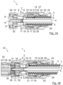
- the cable 3 has an inner conductor 4 , a dielectric 5 concentrically enclosing the inner conductor 4 , an outer conductor 6 concentrically enclosing the dielectric and a cable jacket 7 concentrically enclosing the outer conductor 6 .
- the outer conductor 6 is designed as a corrugated metal tube.
- the area between the corrugated metal tube of the outer conductor 6 and the dielectric 5 is preferably filled with air to allow easy bending of such a "corrugated cable”.
- the inner conductor 4 can also be formed as a corrugated metal tube or as a non-corrugated metal tube.
- the inner conductor contact element 8 On the cable side, the inner conductor contact element 8 has a socket-shaped end 11 embodied as a spring contact sleeve for receiving and for the non-positive connection of the inner conductor 4 of the cable 3 .
- the inner conductor contact element 8 On the plug side, the inner conductor contact element 8 preferably has a pin-shaped end 12 for contacting or for connection to the socket-shaped mating contact element of the electrical mating connector (cf. Figure 1B ).
- the end of the inner conductor contact element 8 on the plug side can also be designed in the form of a socket.
- the outer conductor contact element 9 is sleeve-shaped.
- a ring-shaped metallic stop element 13 is arranged on a shoulder formed on the inner lateral surface of the outer conductor contact element 9 in the direction of the cable 3 .
- the stop element 13 is preferably connected to the outer conductor contact element 9 by means of a press fit. However, other fastening techniques are also conceivable, such as a screw connection or a soldered connection. Alternatively, the stop element 13 can also be connected in one piece to the outer conductor contact element 9 be.
- a compression sleeve 14 is arranged axially adjacent to the stop element 13 in the direction of the cable 3 .
- the compression sleeve 14 In the unassembled state of the connector assembly 1, in which the cable 3 is not yet connected to the connector 2, the compression sleeve 14 is arranged axially within the connector 1 movable. In the assembled state of the plug connector arrangement 1, a press connection is formed between the stop element 13 and the compression sleeve 14, in which the axial end 15 of the outer conductor 6 of the cable 3, which is exposed from the cable jacket 7, is held between an end face of the stop element 13 designed as a stop surface 16 and the end region 17 on the plug side the compression sleeve 14 is clamped.
- the stop element 13 has a tapering outer diameter in the direction of the cable 3 .
- the tapering of the outer diameter of the stop element 13 is formed only in a region on the inner surface of the sleeve-shaped stop element 13 in which the stop element 13 is extended in the direction of the cable 3 by an axial extension 18 with a conical outer surface.
- the axial extension 18 with the conical outer lateral surface is preferably positioned radially on the stop element 13 in such a way that during the assembly process the tip of the conical extension 18 of the stop element 13 pierces precisely into the cable 3 between the dielectric 5 and the outer conductor 6 and the axial end 15 of the outer conductor 6 deflects axially and radially outwards.
- the inner lateral surface 19 of the compression sleeve 14 is thread-shaped, which corresponds to the thread-shaped outer lateral surface 20 of the outer conductor 6 of the cable 3 and consequently has the same thread pitch and the same tooth flank shape and size.
- the corrugated cable is screwed into the compression sleeve 14 with the outer conductor 6 exposed by the cable sheath 7 .
- a longitudinal section of the axial end 15 of the outer conductor 6 is unscrewed from the foremost turn of the thread-shaped inner lateral surface 19 of the compression sleeve 14, which is required for reliable clamping between the stop element 13 and the compression sleeve 14.
- the compression sleeve 14 is preferably made of a plastic material in order to achieve sufficient elasticity for the axial end area to tilt relative to the remaining area of the compression sleeve 14 .
- a metallic material can also be used as an alternative.
- the compression sleeve 14 is guided in the end region 21 of the sleeve-shaped outer conductor contact element 9 on the cable side.
- a fastening sleeve 22 acts axially on the compression sleeve 14 in the direction of the stop element 13 and presses the plug-side end region 17 of the compression sleeve 14 against the stop surface 16 of the stop element 13.
- the fastening sleeve 22 is attached to the plug-side end 23 via a screw connection or alternatively via a press connection on the outer lateral surface of the outer conductor contact element 9 and has a cable-side end 24 front-end termination area 25 with a through-hole 26 for carrying out the cable 3 .
- the assembly process between the fastening sleeve 22 and the compression sleeve 14 takes place via a stop surface 27 of the fastening sleeve 22 formed on the inside of the end region 25 on the end face, which presses against a counter-stop surface 28 of the compression sleeve 14, which is attached to a flange-, web- or shoulder-shaped area 29 or alternatively to the cable-side end face of the compression sleeve 14 is formed.
- the mechanical fastening between the electrical plug connector 2 and the associated electrical mating connector 32 of the electrical plug connection 33 takes place in a known manner via a union nut 34 which is movably attached to the plug connector 2 .
- the internal thread formed on the inner lateral surface of the union nut 34 can be screwed to a corresponding external thread which is formed on the outer lateral surface of the outer conductor contact element 35 of the mating connector 32 .
- the outer conductor contact element 35 of the mating connector 32 encloses a dielectric 36 of the mating connector 32.
- the dielectric 36 of the mating connector 32 encloses the inner conductor 37 of the mating connector 32.
- a spring contact sleeve 38 is formed, in which the inner conductor contact element 8 of the connector 2 is added.
- a further spring contact sleeve 39 is inserted into the outer conductor contact element 35 of the mating connector 32 , preferably by means of a press fit, and makes contact with the inner lateral surface of the outer conductor contact element 9 of the connector 2 .
- the electrical connector 2 is shown without the cable 3 for the sake of clarity.
- the compression sleeve 14 has a slot-shaped recess 40 which is designed as a through hole between the inner lateral surface and the outer lateral surface.
- This slot-shaped recess 40 preferably runs along a turn of the thread-shaped inner lateral surface 19.
- the slot-shaped recess 40 extends only over an angular segment that is reduced by 360° compared to the full angular circumference.
- the normal vector L SEP of the axial end face 42 of the axial end region 41 of the compression sleeve 14 in the non-assembled state Figure 2A rotated by an orientation angle ⁇ A relative to the longitudinal axis L P of the compression sleeve 14 or the longitudinal axis L S of the connector 2 .
- the orientation angle ⁇ A preferably corresponds to the pitch angle of the thread of the thread-shaped inner surface of the compression sleeve 14.
- the axial end face 42 of the axial end portion 41 of the compression sleeve 14 is thus opposite a formed in the longitudinal direction L S of the connector 2 aligned axial end face as an inclined plane.
- the slot-shaped recess 40 In the assembled state of the connector 2, in which the axial end 15 of the outer conductor 8 of the cable 3 is clamped between the stop element 13 and the compression sleeve 14, the slot-shaped recess 40 according to FIG Figure 2B preferably closed.
- an axial end area 41 of the compression sleeve 14 which is arranged next to the stop element 13 on the plug side, is tilted relative to the remaining area of the compression sleeve 14 .
- the longitudinal axis L P of the compression sleeve 14, the longitudinal axis L A of the stop element 13 and the longitudinal axis L S of the plug connector 2 run according to FIG Figure 2A on a common line.
- the longitudinal axis L AEP of the tilted axial end region 41 of the compression sleeve 14 is aligned with the longitudinal axis L A of the stop element 13, which corresponds to the longitudinal axis L S of the connector 2 Figure 2B tilted by a tilt angle ⁇ K.
- the axial end 15 of the outer conductor 6 of the cable 3 is optimally clamped over the entire angular circumference of 360° between the compression sleeve 14 and the stop element 13 and a constant contact pressure and thus a constant contact resistance between the corrugated outer conductor 8 of the cable 3 and the outer conductor contact element 9 of the connector 2 realized over the entire angular range of 360 °.
- a compression sleeve 14 with a slot-shaped recess 40 designed as a blind hole can also be used.
- the blind hole is according to Figure 2C preferably formed on the outer lateral surface of the compression sleeve 14 in such a way that the remaining wall of the compression sleeve 14 between the blind hole and the thread-shaped inner lateral surface 19 of the compression sleeve 14 can be deformed by the pressing force during the assembly process for tilting the axial end region 41 by the tilting angle ⁇ K.
- FIGS 3A to 3D represent the assembly process between the stop element 13 and the compression sleeve 14, which is slotted through a slot-shaped recess 40, in which the normal vector L SEP of the axial end face 42 of the axial end region 41 of the compression sleeve 14 in the direction of the longitudinal axis L A , L S , L P of the stop element 13, the connector 2 and the compression sleeve 14 is directed.
- Such a non-skew configuration of an axial end face 42 of the axial end region 41 of the compression sleeve 14 forms at least over a specific angular segment on the axial end face 42 a ridge-like area 43, such as in particular Figure 3A can be seen.
- first contact between the stop surface 16 of the stop element 13 and the connector-side axial end region 17 of the compression sleeve 14 only occurs in a small angular segment of the compression sleeve 14.
- This contacting angular segment is preferably located opposite the angular segment in which the ridge-shaped area is located 43 forms on the compression sleeve 14 (in the right area of the Figure 3A ).
- the slot-shaped recess 40 in the compression sleeve 14 is still completely open at this point in the process.
- a fourth process point in time of the assembly process which 3D is held, is the upsetting of burr-shaped area 43 of the compression sleeve 14 on the opposite stop surface 16 of the stop element 13 completed.
- the ridge-like area 43 of the compression sleeve 14 is completely compressed or "leveled”.
- the slot-shaped recess 40 in the compression sleeve 14 is completely closed at this point in the process. This is in 3D not shown axial end 15 of the outer conductor 8 of the cable 3 between the connector-side axial end portion 17 of the compression sleeve 14 and the stop surface 16 of the stop element 13 is clamped without the presence of an air gap over the entire circumference of 360 °.
- the compression sleeve 14 is designed without a slot-shaped recess 40 .
- the entire compression sleeve 14 is tilted.
- the counterstop surface 28 of the compression sleeve 14 has a Orientation parallel to the longitudinal axis L A of the stop element 13 or to the longitudinal axis L S of the connector 2.
- the connector-side end face 42 of the compression sleeve 14 is inclined ⁇ A to the longitudinal axis L P of the compression sleeve 14 at the level of the tilt angle ⁇ K , i.e. the normal vector L SEP of the connector-side end face 42 of the compression sleeve 14 is by the alignment angle ⁇ A with respect to the longitudinal axis L P of the compression sleeve 14 rotated.
- the connector-side end region 17 of the compression sleeve 14 is pressed over the entire angular circumference of 360° against the stop surface 16 of the conically shaped axial extension 18 of the stop element 13.
- the axial end 15 of the outer conductor 6 of the cable 3 is thus optimally clamped over the entire angular circumference of 360° between the compression sleeve 14 and the stop element 13 without the presence of an air gap.
- the cable-side end region 21 of the sleeve-shaped outer conductor contact element 9 is preferably shorter and designed with a larger inner diameter than in the first variant.
- a recess 44 in the form of a slot is formed in the stop element 13 .
- the formation of the slot-shaped recess 44 in the stop element 13 is realized in the stop element 13 on the cable side an axial end area 45 of the stop element 13, which has a certain elastic mobility in relation to the remaining area of the stop element 13.
- the shape of the slot-shaped recess 44 in the stop element 13 the technical features already explained for the slot-shaped 40 of the compression sleeve 14 apply equivalently.
- the cable-side end face 42 of the compression sleeve 14 has an obliquity ⁇ A to the longitudinal axis L P of the compression sleeve 14 at the level of the tilt angle ⁇ K , ie the normal vector L SEP of the end face 42 of the compression sleeve 14 is rotated by the orientation angle ⁇ A relative to the longitudinal axis L P of the compression sleeve 14 .
- the plug-side axial end area 17 of the compression sleeve 14 is pressed over the entire angular circumference of 360° to the stop surface 16 of the conical axial extension 18 of the Stop element 13 pressed.
- the axial end 15 of the outer conductor 6 of the cable 3 is optimal without the presence of an air gap the entire angle of 360 ° between the compression sleeve 14 and the stop element 13 is clamped.
- the stop element 13 is tilted by the tilting angle ⁇ K during the assembly process.
- the inner diameter of the outer conductor contact element 9 is to be increased slightly and the end contact surface of the stop element 13 on the outer conductor contact element 9 is designed with a skew.
- the plug-side end face 42 of the compression sleeve 14 also has a skewness ⁇ A to the longitudinal axis L P of the compression sleeve 14 at the level of the tilt angle ⁇ K , i.e. the normal vector L SEP of the end face 42 of the compression sleeve 14 is offset by the alignment angle ⁇ A relative to the longitudinal axis L P Press sleeve 14 rotated.
- the stop element 13 is tilted in that the plug-side axial end region 17 of the compression sleeve 14 presses against the stop surface 16 of the stop element 13 .
- the plug-side axial end region 17 of the compression sleeve 14 is pressed over the entire angular circumference of 360° against the stop surface 16 of the conically shaped axial extension 18 of the stop element 13.
- the axial end 15 of the outer conductor 6 of the cable 3 is thus optimally clamped over the entire angular circumference of 360° between the compression sleeve 14 and the stop element 13 without the presence of an air gap.
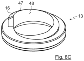
- the plane 46 which is spanned by an edge 47 between the end face, ie the stop surface 16, and the inner lateral surface 48 of the stop element 13, has an obliquity ⁇ A at the level of the tilt angle ⁇ K , ie the normal vector L KEA of this plane 46 rotated by the orientation angle ⁇ A to the longitudinal axis L S of the connector 2 or to the longitudinal axis L P of the compression sleeve 14 or to the longitudinal axis L A of the stop element 13 .
- the connector-side end region 17 of the compression sleeve 14 is pressed over the entire angular circumference of 360° against the stop surface 16 of the conically shaped axial extension 18 of the stop element 13.
- the axial end 15 of the outer conductor 6 of the cable 3 is thus optimally clamped over the entire angular circumference of 360° between the compression sleeve 14 and the stop element 13 without the presence of an air gap.
- a plug-side end face 42 of the compression sleeve 14 whose Normal vector L SEP is directed in the direction of the longitudinal axis LS of the connector 2 and on which a ridge-like portion 43 is formed in a certain angular range can be used.
- the edge 47 between the end face, i.e. the stop surface 16 and the inner lateral surface 48 of the stop element 13 has a helical course in the direction of the longitudinal axis L S of the connector 2, which corresponds to the helical course of the thread turn on the inner lateral surface 19 of the compression sleeve 14.
- the conically shaped area of the stop surface 16 of the stop element 13 thus runs parallel to the tooth flank surface of the foremost turn of the internal thread formed in the compression sleeve 14 .
- the stop surface 16 of the stop element 13 preferably has a conical flank.
- the axial end 15 of the outer conductor 6 of the cable 3 is thus clamped with constant contact pressure over the entire angular circumference of 360° between the axial end region 17 of the compression sleeve 14 and the stop surface 16 of the stop element 13 .
Landscapes
- Details Of Connecting Devices For Male And Female Coupling (AREA)
Claims (15)
- Connecteur enfichable électrique (2) destiné à un câble (3), présentant une douille de serrage (14) et un élément de butée (13), dans lequel l'élément de butée (13) est agencé axialement à proximité de la douille de serrage (14) dans une direction d'enfichage du connecteur enfichable électrique (2) et est connecté directement ou indirectement à la douille de serrage (14),dans lequel la douille de serrage (14) présente une surface d'enveloppe intérieure (19) en forme de filetage qui est configurée pour pouvoir être vissée avec une surface d'enveloppe extérieure (20) en forme de filetage d'un conducteur extérieur (6) du câble (3), etdans lequel la connexion de la douille de serrage (14) et de l'élément du butée (13) est configurée de telle sorte qu'une extrémité axiale (15) du conducteur extérieur (8) peut être coincée entre une zone d'extrémité axiale (41) de la douille de serrage (14) voisine de l'élément de butée (13) et une zone d'extrémité axiale (45) de l'élément de butée (13) voisine de la douille de serrage (14),caractérisé en ce quea) lorsque le connecteur enfichable (2) et le câble (3) sont montés, un axe longitudinal de la douille de serrage (14), au moins dans la zone d'extrémité axiale (41) de la douille de serrage (14), est incliné d'un angle d'inclinaison (ΦK) par rapport à un axe longitudinal de l'élément de butée (13), au moins dans la zone d'extrémité axiale (45) de l'élément de butée (13) oub) un vecteur normal d'un plan (46), qui passe par une arête (47) entre une surface frontale (16) et une surface d'enveloppe intérieure (48) de l'élément de butée (13), est tourné d'un angle d'orientation (ΦA) par rapport à l'axe longitudinal de la douille de serrage (14) ouc) l'arête (47) présente une forme hélicoïdale dans une direction d'axe longitudinal du connecteur enfichable (2).
- Connecteur enfichable électrique (2) selon la revendication 1,
caractérisé
en ce que, dans la zone d'extrémité axiale (44) de l'élément de butée (13), la surface frontale (16) est configurée avec un diamètre dégressif. - Connecteur enfichable électrique (2) selon la revendication 1 ou 2,
caractérisé
en ce que l'angle d'inclinaison (ΦK) et l'angle d'orientation (ΦA) se trouvent respectivement sur une plage angulaire de +/- 20% par rapport à un angle de torsion d'un filetage de la surface d'enveloppe intérieure (19) en forme de filetage, de préférence sur une plage angulaire de +/- 10% par rapport à l'angle de torsion, de façon particulièrement préférée sur une plage angulaire de +/- 5% par rapport à l'angle de torsion et dans le meilleur des cas correspond à l'angle de torsion. - Connecteur enfichable électrique (2) selon une des revendications 1 à 3,
caractérisé
en ce qu'un vecteur normal d'une surface frontale (42) située du côté du connecteur de la douille de serrage (14) est tourné de l'angle d'orientation (ΦA) par rapport à l'axe longitudinal de la douille de serrage (14). - Connecteur enfichable électrique (2) selon une des revendications 1 à 3,
caractérisé
en ce qu'une plage, de préférence une plage en forme de nervure (43) de la zone d'extrémité axiale (41) de la douille de serrage (14) est comprimée axialement lorsque le connecteur enfichable (2) et le câble (3) sont montés. - Connecteur enfichable électrique (2) selon une des revendications 3 à 5,
caractérisé
en ce que l'axe longitudinal de la douille de serrage (14) est incliné, au moins dans la zone d'extrémité axiale (41) de la douille de serrage (14), par rapport à un axe longitudinal du connecteur enfichable électrique (2). - Connecteur enfichable électrique (2) selon la revendication 6,
caractérisé
en ce qu'une cavité oblongue (40) est formée dans la douille de serrage (14). - Connecteur enfichable électrique (2) selon la revendication 7,
caractérisé
en ce qu'une extension longitudinale de la cavité oblongue (40) est formée le long du filetage, de préférence le long d'un fond de filet du filetage, ou perpendiculairement à l'axe longitudinal de la douille de serrage (14). - Connecteur enfichable électrique (2) selon la revendication 7 ou 8,
caractérisé
en ce que la cavité oblongue (40) de la douille de serrage (14) est configurée comme un trou traversant ou comme un trou borgne. - Connecteur enfichable électrique (2) selon la revendication 6,
caractérisé
en ce que l'axe longitudinal de l'ensemble de la douille de serrage (14) est incliné par rapport à l'axe longitudinal du connecteur enfichable électrique (2). - Connecteur enfichable électrique (2) selon une des revendications 3 à 5,
caractérisé
en ce que l'axe longitudinal de l'élément de butée (13) est incliné au moins dans la zone d'extrémité axiale (45) de l'élément de butée (13) par rapport à un axe longitudinal du connecteur enfichable électrique (2). - Connecteur enfichable électrique (2) selon la revendication 11,
caractérisé
en ce qu'une cavité oblongue (44) est configurée dans l'élément de butée (13). - Connecteur enfichable électrique (2) selon la revendication 11,
caractérisé
en ce que l'axe longitudinal de l'élément de butée (13) est incliné par rapport à l'axe longitudinal du connecteur enfichable électrique (2). - Agencement de connecteur enfichable électrique comprenant un connecteur enfichable électrique (2) selon une des revendications 1 à 13 et le câble (3), dont le conducteur extérieur (3) est vissé dans la douille de serrage (14) du connecteur enfichable électrique (2).
- Connecteur enfichable électrique (33) comprenant un agencement de connecteur enfichable électrique (1) selon la revendication 14 et un connecteur enfichable électrique homologue (32) correspondant.
Priority Applications (3)
| Application Number | Priority Date | Filing Date | Title |
|---|---|---|---|
| EP21174634.2A EP4092835B1 (fr) | 2021-05-19 | 2021-05-19 | Connecteur enfichable électrique, agencement de connecteur enfichable électrique et connecteur enfichable électrique |
| CN202210282465.5A CN115377757A (zh) | 2021-05-19 | 2022-03-22 | 电插头连接器、电插头连接器组件和电插头连接 |
| US17/717,498 US11881663B2 (en) | 2021-05-19 | 2022-04-11 | Electrical plug connector, electrical plug connector assembly, and electrical plug connection |
Applications Claiming Priority (1)
| Application Number | Priority Date | Filing Date | Title |
|---|---|---|---|
| EP21174634.2A EP4092835B1 (fr) | 2021-05-19 | 2021-05-19 | Connecteur enfichable électrique, agencement de connecteur enfichable électrique et connecteur enfichable électrique |
Publications (3)
| Publication Number | Publication Date |
|---|---|
| EP4092835A1 EP4092835A1 (fr) | 2022-11-23 |
| EP4092835C0 EP4092835C0 (fr) | 2023-07-05 |
| EP4092835B1 true EP4092835B1 (fr) | 2023-07-05 |
Family
ID=76011770
Family Applications (1)
| Application Number | Title | Priority Date | Filing Date |
|---|---|---|---|
| EP21174634.2A Active EP4092835B1 (fr) | 2021-05-19 | 2021-05-19 | Connecteur enfichable électrique, agencement de connecteur enfichable électrique et connecteur enfichable électrique |
Country Status (3)
| Country | Link |
|---|---|
| US (1) | US11881663B2 (fr) |
| EP (1) | EP4092835B1 (fr) |
| CN (1) | CN115377757A (fr) |
Family Cites Families (13)
| Publication number | Priority date | Publication date | Assignee | Title |
|---|---|---|---|---|
| US3671926A (en) * | 1970-08-03 | 1972-06-20 | Lindsay Specialty Prod Ltd | Coaxial cable connector |
| US5267877A (en) * | 1992-11-23 | 1993-12-07 | Dynawave Incorporated | Coaxial connector for corrugated conduit |
| GB2303749B (en) * | 1993-06-01 | 1997-04-16 | Spinner Gmbh Elektrotech | A plug-in connector for corrugated tube coaxial cables |
| US5334051A (en) * | 1993-06-17 | 1994-08-02 | Andrew Corporation | Connector for coaxial cable having corrugated outer conductor and method of attachment |
| DE4344328C1 (de) * | 1993-12-23 | 1995-01-12 | Spinner Gmbh Elektrotech | Steckverbinder für Koaxialkabel mit gewelltem Außenleiter |
| US5766037A (en) * | 1996-10-11 | 1998-06-16 | Radio Frequency Systems, Inc. | Connector for a radio frequency cable |
| US6019635A (en) * | 1998-02-25 | 2000-02-01 | Radio Frequency Systems, Inc. | Coaxial cable connector assembly |
| US7029326B2 (en) * | 2004-07-16 | 2006-04-18 | John Mezzalingua Associates, Inc. | Compression connector for coaxial cable |
| US9172156B2 (en) * | 2010-10-08 | 2015-10-27 | John Mezzalingua Associates, LLC | Connector assembly having deformable surface |
| US8287309B1 (en) * | 2011-07-01 | 2012-10-16 | Belden Inc. | Hardline connector |
| US9166307B2 (en) * | 2013-03-15 | 2015-10-20 | Perfectvision Manufacturing, Inc. | Enhanced continuity coaxial connectors with socketed nut |
| JP6299003B2 (ja) * | 2014-06-16 | 2018-03-28 | ヒロセ電機株式会社 | 複数コネクタ一括嵌合アダプタ |
| DE102015003579A1 (de) * | 2015-03-19 | 2016-09-22 | Kathrein-Werke Kg | HF-Steckverbinder zur lotfreien Kontaktierung eines Koaxialkabels |
-
2021
- 2021-05-19 EP EP21174634.2A patent/EP4092835B1/fr active Active
-
2022
- 2022-03-22 CN CN202210282465.5A patent/CN115377757A/zh active Pending
- 2022-04-11 US US17/717,498 patent/US11881663B2/en active Active
Also Published As
| Publication number | Publication date |
|---|---|
| EP4092835C0 (fr) | 2023-07-05 |
| US11881663B2 (en) | 2024-01-23 |
| EP4092835A1 (fr) | 2022-11-23 |
| CN115377757A (zh) | 2022-11-22 |
| US20220376447A1 (en) | 2022-11-24 |
Similar Documents
| Publication | Publication Date | Title |
|---|---|---|
| EP2869405B1 (fr) | Dispositif de raccordement destiné au raccordement électrique de deux cartes de circuit imprimé | |
| EP1560294B1 (fr) | Connecteur pour câble coaxial avec un conducteur extérieur ondulé | |
| EP0494438B1 (fr) | Embout pour extrémité de câble | |
| EP0762545B1 (fr) | Dispositif pour la fixation d'une fiche coaxiale à un câble coaxial | |
| EP1028498B1 (fr) | Connecteur pour câble coaxial ayant un conducteur extérieur lisse | |
| DE2343030A1 (de) | Anschlussvorrichtung fuer koaxialkabel | |
| DE19738517C1 (de) | Kabelverschraubung für Erdungs- oder Abschirmkabel mit einem gegen das Kabel preßbaren Klemmeinsatz | |
| DE102011108123B4 (de) | Kabelanschlussbauteil sowie Kabelanschlusseinrichtung und Kabelverbindungseinrichtung mit einem Kabelanschlussbauteil | |
| DE102004043518B3 (de) | Vorrichtung zum Anschluss eines Koaxialkabels an ein Gehäuse | |
| EP3579346B1 (fr) | Connecteur enfichable électrique pour cartes de circuits imprimés | |
| EP2053705B1 (fr) | Fiche coudée | |
| DE102017126185B4 (de) | Elektrisches Kontaktelement | |
| EP4092835B1 (fr) | Connecteur enfichable électrique, agencement de connecteur enfichable électrique et connecteur enfichable électrique | |
| EP2424046B1 (fr) | Elément de contact à conducteur extérieur pour extrémités de câble coaxiales | |
| DE102023004088B4 (de) | Koaxialverbinder | |
| EP0643255A1 (fr) | Lampe électrique | |
| DE3935360C2 (fr) | ||
| DE2417579A1 (de) | Elektrischer verbinder und verfahren zum herstellen einer elektrischen verbindung | |
| EP1632009B1 (fr) | Element de contact et chambre de conduction complementaire pour un connecteur male ou femelle utilise en technique de raccordement autodenudant | |
| DE2601429C3 (de) | Koaxialkabel-Anschlußklemme | |
| DE102022206634A1 (de) | Hochvoltschnittstelle | |
| EP4254683B1 (fr) | Connecteur enfichable rond et procédé de fabrication d'un connecteur enfichable rond | |
| EP0884800B1 (fr) | Dispositif de connexion pour câble coaxial | |
| DE102016101507B4 (de) | Axialanschlussvorrichtung und Axialanschlussklemme | |
| DE19964299B4 (de) | Steckverbinder für abstrahlende Koaxialkabel |
Legal Events
| Date | Code | Title | Description |
|---|---|---|---|
| PUAI | Public reference made under article 153(3) epc to a published international application that has entered the european phase |
Free format text: ORIGINAL CODE: 0009012 |
|
| STAA | Information on the status of an ep patent application or granted ep patent |
Free format text: STATUS: REQUEST FOR EXAMINATION WAS MADE |
|
| 17P | Request for examination filed |
Effective date: 20211227 |
|
| AK | Designated contracting states |
Kind code of ref document: A1 Designated state(s): AL AT BE BG CH CY CZ DE DK EE ES FI FR GB GR HR HU IE IS IT LI LT LU LV MC MK MT NL NO PL PT RO RS SE SI SK SM TR |
|
| GRAP | Despatch of communication of intention to grant a patent |
Free format text: ORIGINAL CODE: EPIDOSNIGR1 |
|
| STAA | Information on the status of an ep patent application or granted ep patent |
Free format text: STATUS: GRANT OF PATENT IS INTENDED |
|
| RIC1 | Information provided on ipc code assigned before grant |
Ipc: H01R 103/00 20060101ALN20221130BHEP Ipc: H01R 24/56 20110101ALI20221130BHEP Ipc: H01R 9/05 20060101AFI20221130BHEP |
|
| INTG | Intention to grant announced |
Effective date: 20221213 |
|
| GRAS | Grant fee paid |
Free format text: ORIGINAL CODE: EPIDOSNIGR3 |
|
| GRAA | (expected) grant |
Free format text: ORIGINAL CODE: 0009210 |
|
| STAA | Information on the status of an ep patent application or granted ep patent |
Free format text: STATUS: THE PATENT HAS BEEN GRANTED |
|
| AK | Designated contracting states |
Kind code of ref document: B1 Designated state(s): AL AT BE BG CH CY CZ DE DK EE ES FI FR GB GR HR HU IE IS IT LI LT LU LV MC MK MT NL NO PL PT RO RS SE SI SK SM TR |
|
| REG | Reference to a national code |
Ref country code: CH Ref legal event code: EP |
|
| REG | Reference to a national code |
Ref country code: AT Ref legal event code: REF Ref document number: 1585694 Country of ref document: AT Kind code of ref document: T Effective date: 20230715 |
|
| REG | Reference to a national code |
Ref country code: DE Ref legal event code: R096 Ref document number: 502021000952 Country of ref document: DE |
|
| REG | Reference to a national code |
Ref country code: IE Ref legal event code: FG4D Free format text: LANGUAGE OF EP DOCUMENT: GERMAN |
|
| U01 | Request for unitary effect filed |
Effective date: 20230713 |
|
| U07 | Unitary effect registered |
Designated state(s): AT BE BG DE DK EE FI FR IT LT LU LV MT NL PT SE SI Effective date: 20230721 |
|
| REG | Reference to a national code |
Ref country code: LT Ref legal event code: MG9D |
|
| PG25 | Lapsed in a contracting state [announced via postgrant information from national office to epo] |
Ref country code: GR Free format text: LAPSE BECAUSE OF FAILURE TO SUBMIT A TRANSLATION OF THE DESCRIPTION OR TO PAY THE FEE WITHIN THE PRESCRIBED TIME-LIMIT Effective date: 20231006 |
|
| PG25 | Lapsed in a contracting state [announced via postgrant information from national office to epo] |
Ref country code: ES Free format text: LAPSE BECAUSE OF FAILURE TO SUBMIT A TRANSLATION OF THE DESCRIPTION OR TO PAY THE FEE WITHIN THE PRESCRIBED TIME-LIMIT Effective date: 20230705 |
|
| PG25 | Lapsed in a contracting state [announced via postgrant information from national office to epo] |
Ref country code: IS Free format text: LAPSE BECAUSE OF FAILURE TO SUBMIT A TRANSLATION OF THE DESCRIPTION OR TO PAY THE FEE WITHIN THE PRESCRIBED TIME-LIMIT Effective date: 20231105 |
|
| PG25 | Lapsed in a contracting state [announced via postgrant information from national office to epo] |
Ref country code: RS Free format text: LAPSE BECAUSE OF FAILURE TO SUBMIT A TRANSLATION OF THE DESCRIPTION OR TO PAY THE FEE WITHIN THE PRESCRIBED TIME-LIMIT Effective date: 20230705 Ref country code: NO Free format text: LAPSE BECAUSE OF FAILURE TO SUBMIT A TRANSLATION OF THE DESCRIPTION OR TO PAY THE FEE WITHIN THE PRESCRIBED TIME-LIMIT Effective date: 20231005 Ref country code: IS Free format text: LAPSE BECAUSE OF FAILURE TO SUBMIT A TRANSLATION OF THE DESCRIPTION OR TO PAY THE FEE WITHIN THE PRESCRIBED TIME-LIMIT Effective date: 20231105 Ref country code: HR Free format text: LAPSE BECAUSE OF FAILURE TO SUBMIT A TRANSLATION OF THE DESCRIPTION OR TO PAY THE FEE WITHIN THE PRESCRIBED TIME-LIMIT Effective date: 20230705 Ref country code: GR Free format text: LAPSE BECAUSE OF FAILURE TO SUBMIT A TRANSLATION OF THE DESCRIPTION OR TO PAY THE FEE WITHIN THE PRESCRIBED TIME-LIMIT Effective date: 20231006 Ref country code: ES Free format text: LAPSE BECAUSE OF FAILURE TO SUBMIT A TRANSLATION OF THE DESCRIPTION OR TO PAY THE FEE WITHIN THE PRESCRIBED TIME-LIMIT Effective date: 20230705 |
|
| PG25 | Lapsed in a contracting state [announced via postgrant information from national office to epo] |
Ref country code: PL Free format text: LAPSE BECAUSE OF FAILURE TO SUBMIT A TRANSLATION OF THE DESCRIPTION OR TO PAY THE FEE WITHIN THE PRESCRIBED TIME-LIMIT Effective date: 20230705 |
|
| REG | Reference to a national code |
Ref country code: DE Ref legal event code: R097 Ref document number: 502021000952 Country of ref document: DE |
|
| PG25 | Lapsed in a contracting state [announced via postgrant information from national office to epo] |
Ref country code: SM Free format text: LAPSE BECAUSE OF FAILURE TO SUBMIT A TRANSLATION OF THE DESCRIPTION OR TO PAY THE FEE WITHIN THE PRESCRIBED TIME-LIMIT Effective date: 20230705 Ref country code: RO Free format text: LAPSE BECAUSE OF FAILURE TO SUBMIT A TRANSLATION OF THE DESCRIPTION OR TO PAY THE FEE WITHIN THE PRESCRIBED TIME-LIMIT Effective date: 20230705 Ref country code: CZ Free format text: LAPSE BECAUSE OF FAILURE TO SUBMIT A TRANSLATION OF THE DESCRIPTION OR TO PAY THE FEE WITHIN THE PRESCRIBED TIME-LIMIT Effective date: 20230705 Ref country code: SK Free format text: LAPSE BECAUSE OF FAILURE TO SUBMIT A TRANSLATION OF THE DESCRIPTION OR TO PAY THE FEE WITHIN THE PRESCRIBED TIME-LIMIT Effective date: 20230705 |
|
| PLBE | No opposition filed within time limit |
Free format text: ORIGINAL CODE: 0009261 |
|
| STAA | Information on the status of an ep patent application or granted ep patent |
Free format text: STATUS: NO OPPOSITION FILED WITHIN TIME LIMIT |
|
| 26N | No opposition filed |
Effective date: 20240408 |
|
| U21 | Renewal fee for the european patent with unitary effect paid with additional fee |
Year of fee payment: 4 Effective date: 20240712 |
|
| PGFP | Annual fee paid to national office [announced via postgrant information from national office to epo] |
Ref country code: CH Payment date: 20240725 Year of fee payment: 4 |
|
| PG25 | Lapsed in a contracting state [announced via postgrant information from national office to epo] |
Ref country code: MC Free format text: LAPSE BECAUSE OF FAILURE TO SUBMIT A TRANSLATION OF THE DESCRIPTION OR TO PAY THE FEE WITHIN THE PRESCRIBED TIME-LIMIT Effective date: 20230705 |
|
| PG25 | Lapsed in a contracting state [announced via postgrant information from national office to epo] |
Ref country code: MC Free format text: LAPSE BECAUSE OF FAILURE TO SUBMIT A TRANSLATION OF THE DESCRIPTION OR TO PAY THE FEE WITHIN THE PRESCRIBED TIME-LIMIT Effective date: 20230705 |
|
| PG25 | Lapsed in a contracting state [announced via postgrant information from national office to epo] |
Ref country code: IE Free format text: LAPSE BECAUSE OF NON-PAYMENT OF DUE FEES Effective date: 20240519 |
|
| PG25 | Lapsed in a contracting state [announced via postgrant information from national office to epo] |
Ref country code: CY Free format text: LAPSE BECAUSE OF FAILURE TO SUBMIT A TRANSLATION OF THE DESCRIPTION OR TO PAY THE FEE WITHIN THE PRESCRIBED TIME-LIMIT; INVALID AB INITIO Effective date: 20210519 |
|
| PG25 | Lapsed in a contracting state [announced via postgrant information from national office to epo] |
Ref country code: HU Free format text: LAPSE BECAUSE OF FAILURE TO SUBMIT A TRANSLATION OF THE DESCRIPTION OR TO PAY THE FEE WITHIN THE PRESCRIBED TIME-LIMIT; INVALID AB INITIO Effective date: 20210519 |
|
| REG | Reference to a national code |
Ref country code: CH Ref legal event code: H13 Free format text: ST27 STATUS EVENT CODE: U-0-0-H10-H13 (AS PROVIDED BY THE NATIONAL OFFICE) Effective date: 20251223 |
|
| U90 | Renewal fees not paid: noting of loss of rights |
Free format text: RENEWAL FEE NOT PAID FOR YEAR 05 Effective date: 20251217 |
|
| PG25 | Lapsed in a contracting state [announced via postgrant information from national office to epo] |
Ref country code: CH Free format text: LAPSE BECAUSE OF NON-PAYMENT OF DUE FEES Effective date: 20250531 |
|
| GBPC | Gb: european patent ceased through non-payment of renewal fee |
Effective date: 20250519 |
|
| U93 | Unitary patent lapsed |
Free format text: RENEWAL FEE NOT PAID Effective date: 20250531 |
|
| PG25 | Lapsed in a contracting state [announced via postgrant information from national office to epo] |
Ref country code: GB Free format text: LAPSE BECAUSE OF NON-PAYMENT OF DUE FEES Effective date: 20250519 |