EP4092922B1 - Précodage d'informations - Google Patents
Précodage d'informations Download PDFInfo
- Publication number
- EP4092922B1 EP4092922B1 EP22170400.0A EP22170400A EP4092922B1 EP 4092922 B1 EP4092922 B1 EP 4092922B1 EP 22170400 A EP22170400 A EP 22170400A EP 4092922 B1 EP4092922 B1 EP 4092922B1
- Authority
- EP
- European Patent Office
- Prior art keywords
- index
- layer
- measurement window
- reported
- components
- Prior art date
- Legal status (The legal status is an assumption and is not a legal conclusion. Google has not performed a legal analysis and makes no representation as to the accuracy of the status listed.)
- Active
Links
Images






Classifications
-
- H—ELECTRICITY
- H04—ELECTRIC COMMUNICATION TECHNIQUE
- H04B—TRANSMISSION
- H04B7/00—Radio transmission systems, i.e. using radiation field
- H04B7/02—Diversity systems; Multi-antenna system, i.e. transmission or reception using multiple antennas
- H04B7/04—Diversity systems; Multi-antenna system, i.e. transmission or reception using multiple antennas using two or more spaced independent antennas
- H04B7/0413—MIMO systems
- H04B7/0456—Selection of precoding matrices or codebooks, e.g. using matrices antenna weighting
-
- H—ELECTRICITY
- H04—ELECTRIC COMMUNICATION TECHNIQUE
- H04B—TRANSMISSION
- H04B7/00—Radio transmission systems, i.e. using radiation field
- H04B7/02—Diversity systems; Multi-antenna system, i.e. transmission or reception using multiple antennas
- H04B7/04—Diversity systems; Multi-antenna system, i.e. transmission or reception using multiple antennas using two or more spaced independent antennas
- H04B7/0413—MIMO systems
- H04B7/0456—Selection of precoding matrices or codebooks, e.g. using matrices antenna weighting
- H04B7/0478—Special codebook structures directed to feedback optimisation
-
- H—ELECTRICITY
- H04—ELECTRIC COMMUNICATION TECHNIQUE
- H04B—TRANSMISSION
- H04B7/00—Radio transmission systems, i.e. using radiation field
- H04B7/02—Diversity systems; Multi-antenna system, i.e. transmission or reception using multiple antennas
- H04B7/04—Diversity systems; Multi-antenna system, i.e. transmission or reception using multiple antennas using two or more spaced independent antennas
- H04B7/06—Diversity systems; Multi-antenna system, i.e. transmission or reception using multiple antennas using two or more spaced independent antennas at the transmitting station
- H04B7/0613—Diversity systems; Multi-antenna system, i.e. transmission or reception using multiple antennas using two or more spaced independent antennas at the transmitting station using simultaneous transmission
- H04B7/0615—Diversity systems; Multi-antenna system, i.e. transmission or reception using multiple antennas using two or more spaced independent antennas at the transmitting station using simultaneous transmission of weighted versions of same signal
- H04B7/0619—Diversity systems; Multi-antenna system, i.e. transmission or reception using multiple antennas using two or more spaced independent antennas at the transmitting station using simultaneous transmission of weighted versions of same signal using feedback from receiving side
- H04B7/0621—Feedback content
- H04B7/0626—Channel coefficients, e.g. channel state information [CSI]
-
- H—ELECTRICITY
- H04—ELECTRIC COMMUNICATION TECHNIQUE
- H04B—TRANSMISSION
- H04B7/00—Radio transmission systems, i.e. using radiation field
- H04B7/02—Diversity systems; Multi-antenna system, i.e. transmission or reception using multiple antennas
- H04B7/04—Diversity systems; Multi-antenna system, i.e. transmission or reception using multiple antennas using two or more spaced independent antennas
- H04B7/06—Diversity systems; Multi-antenna system, i.e. transmission or reception using multiple antennas using two or more spaced independent antennas at the transmitting station
- H04B7/0613—Diversity systems; Multi-antenna system, i.e. transmission or reception using multiple antennas using two or more spaced independent antennas at the transmitting station using simultaneous transmission
- H04B7/0615—Diversity systems; Multi-antenna system, i.e. transmission or reception using multiple antennas using two or more spaced independent antennas at the transmitting station using simultaneous transmission of weighted versions of same signal
- H04B7/0619—Diversity systems; Multi-antenna system, i.e. transmission or reception using multiple antennas using two or more spaced independent antennas at the transmitting station using simultaneous transmission of weighted versions of same signal using feedback from receiving side
- H04B7/0621—Feedback content
- H04B7/0634—Antenna weights or vector/matrix coefficients
-
- H—ELECTRICITY
- H04—ELECTRIC COMMUNICATION TECHNIQUE
- H04B—TRANSMISSION
- H04B7/00—Radio transmission systems, i.e. using radiation field
- H04B7/02—Diversity systems; Multi-antenna system, i.e. transmission or reception using multiple antennas
- H04B7/04—Diversity systems; Multi-antenna system, i.e. transmission or reception using multiple antennas using two or more spaced independent antennas
- H04B7/06—Diversity systems; Multi-antenna system, i.e. transmission or reception using multiple antennas using two or more spaced independent antennas at the transmitting station
- H04B7/0613—Diversity systems; Multi-antenna system, i.e. transmission or reception using multiple antennas using two or more spaced independent antennas at the transmitting station using simultaneous transmission
- H04B7/0615—Diversity systems; Multi-antenna system, i.e. transmission or reception using multiple antennas using two or more spaced independent antennas at the transmitting station using simultaneous transmission of weighted versions of same signal
- H04B7/0619—Diversity systems; Multi-antenna system, i.e. transmission or reception using multiple antennas using two or more spaced independent antennas at the transmitting station using simultaneous transmission of weighted versions of same signal using feedback from receiving side
- H04B7/0636—Feedback format
- H04B7/0639—Using selective indices, e.g. of a codebook, e.g. pre-distortion matrix index [PMI] or for beam selection
-
- H—ELECTRICITY
- H04—ELECTRIC COMMUNICATION TECHNIQUE
- H04B—TRANSMISSION
- H04B7/00—Radio transmission systems, i.e. using radiation field
- H04B7/02—Diversity systems; Multi-antenna system, i.e. transmission or reception using multiple antennas
- H04B7/04—Diversity systems; Multi-antenna system, i.e. transmission or reception using multiple antennas using two or more spaced independent antennas
- H04B7/06—Diversity systems; Multi-antenna system, i.e. transmission or reception using multiple antennas using two or more spaced independent antennas at the transmitting station
- H04B7/0613—Diversity systems; Multi-antenna system, i.e. transmission or reception using multiple antennas using two or more spaced independent antennas at the transmitting station using simultaneous transmission
- H04B7/0615—Diversity systems; Multi-antenna system, i.e. transmission or reception using multiple antennas using two or more spaced independent antennas at the transmitting station using simultaneous transmission of weighted versions of same signal
- H04B7/0619—Diversity systems; Multi-antenna system, i.e. transmission or reception using multiple antennas using two or more spaced independent antennas at the transmitting station using simultaneous transmission of weighted versions of same signal using feedback from receiving side
- H04B7/0658—Feedback reduction
Definitions
- the present disclosure relates to methods, apparatuses and computer program products for communicating precoding information between communication devices.
- Communication sessions can be established between two or more communication devices such as user or terminal devices, base stations/access points and/or other nodes.
- Communication session may be provided, for example, by means of a communication network and one or more compatible communication devices.
- a communication device at a network side provides an access point to the system and is provided with an appropriate signal receiving and transmitting apparatus for enabling communications, for example enabling other devices to access the communication system.
- Communication sessions may comprise, for example, communication of data for carrying communications such as voice, video, electronic mail (email), text message, multimedia and/or content data and so on.
- Non-limiting examples of services provided comprise two-way or multi-way calls, data communication, multimedia services and access to a data network system, such as the Internet.
- a mobile or wireless communication system at least a part of a communication session between at least two devices occurs over a wireless or radio link.
- wireless systems comprise public land mobile networks (PLMN), satellite-based communication systems and different wireless local networks, for example wireless local area networks (WLAN).
- PLMN public land mobile networks
- WLAN wireless local area networks
- a user can access the wider communication system by means of an appropriate communication device or terminal.
- a communication device is often referred to as user equipment (UE) or user device.
- UE user equipment
- a communication device is provided with an appropriate signal receiving and transmitting apparatus for enabling communications, for example enabling access to a communication network or communications directly with other users.
- a communication device may access a carrier provided by a station at a radio access network, for example a base station, and transmit and/or receive communications on the carrier.
- Multipath communication may be provide by means of an arrangement known as multiple input/multiple output (MIMO).
- MIMO multiple input/multiple output
- the communication system and associated devices typically operate in accordance with a given standard or specification which sets out what the various entities associated with the system are permitted to do and how that should be achieved. Communication protocols and/or parameters which shall be used for the connection are also typically defined.
- UTRAN 3G radio
- Other examples of communication systems are the long-term evolution (LTE) of the Universal Mobile Telecommunications System (UMTS) radio-access technology and so-called fifth generation (5G) or New Radio (NR) networks.
- 5G is being standardized by the 3rd Generation Partnership Project (3GPP).
- the successive versions of the standard are known as Releases (Rel).
- Rel Releases
- CSI channel state information
- Document R1-2101011 discloses enhancement on CSI measurement and reporting.
- Document R1-2101886 discloses CSI enhancements for MTRP and FDD.
- Document R1-2102062 discloses CSI enhancements for MTRP and FDD.
- Wireless communication systems provide wireless communications to devices connected therein.
- an access point such as a base station is provided for enabling the communications.
- an access architecture a 3GPP 5G radio access architecture with MIMO capability.
- embodiments are not necessarily limited to such an architecture.
- UMTS universal mobile telecommunications system
- UTRAN E-UTRAN
- LTE long term evolution
- LTE-A LTE advanced
- WLAN wireless local area network
- Wi-Fi worldwide interoperability for microwave access
- Bluetooth ® personal communications services
- PCS personal communications services
- WCDMA wideband code division multiple access
- WCDMA wideband code division multiple access
- UWB ultra-wideband
- sensor networks sensor networks
- MANETs mobile ad-hoc networks
- IoT Internet Protocol multimedia subsystems
- IMS Internet Protocol multimedia subsystems
- Figure 1 shows a wireless system 1 comprising a radio access system 2.
- a radio access system can comprise one or a plurality of access points, or base stations 12.
- a base station may provide one or more cells.
- An access point can comprise any node that can transmit/receive radio signals (e.g., a TRP, a 3GPP 5G base station such as gNB, eNB, a user device such as a UE and so forth).
- a communications device 10 is located in the service area of the radio access system 2, and the device 10 can thus communicate with the access point 12.
- the communications 11 from the device 10 to the access point 12 is commonly referred to as uplink (UL).
- the communications 13 from the access point 12 to the device 10 is commonly referred to as downlink (DL).
- the downlink is shown schematically to comprise up to four beams per polarization in spatial domain (SD).
- a 5G based system may be comprised by a terminal or user equipment (UE), a 5G radio access network (5GRAN) or next generation radio access network (NG-RAN), a 5G core network (5GC), one or more application functions (AF) and one or more data networks (DN).
- the 5G-RAN may comprise one or more gNodeB (gNB) or one or more gNodeB (gNB) distributed unit functions connected to one or more gNodeB (gNB) centralized unit functions.
- the 5GC may also comprise entities such as Network Slice Selection Function (NSSF); Network Exposure Function; Network Repository Function (NRF); Policy Control Function (PCF); Unified Data Management (UDM); Application Function (AF); Authentication Server Function (AUSF); an Access and Mobility Management Function (AMF); Session Management Function (SMF) and so on.
- NSSF Network Slice Selection Function
- NRF Network Exposure Function
- PCF Policy Control Function
- UDM Unified Data Management
- AF Application Function
- AUSF Authentication Server Function
- AMF Access and Mobility Management Function
- Session Management Function SMF
- the device 10 may be any suitable communications device adapted for wireless communications.
- a wireless communications device may be provided by any device capable of sending and receiving radio signals.
- Non-limiting examples comprise a mobile station (MS) (e.g., a mobile device such as a mobile phone or what is known as a 'smart phone'), a computer provided with a wireless interface card or other wireless interface facility (e.g., USB dongle), personal data assistant (PDA) or a tablet provided with wireless communication capabilities, machine-type communications (MTC) devices, Internet of Things (IoT) type communications devices or any combinations of these or the like.
- the device may be provided as part of another device.
- the device may receive signals over an air or radio interface via appropriate apparatus for receiving and may transmit signals via appropriate apparatus for transmitting radio signals.
- the communications can occur via multiple paths.
- MIMO type communications device 10 and 12 are provided with multiantenna elements. These are schematically denoted by antenna arrays 14 and 15.
- a communications device such as the access point 12 or the user device 10 is provided with data processing apparatus comprising at least one processor and at least one memory.
- Figure 2 shows an example of a data processing apparatus 50 comprising processor(s) 52, 53 and memory or memories 51.
- Figure 2 further shows connections between the elements of the apparatus and an interface for connecting the data processing apparatus to other components of the device.
- the at least one memory may comprise at least one ROM and/or at least one RAM.
- the communications device may comprise other possible components for use in software and hardware aided execution of tasks it is designed to perform, including control of access to and communications with access systems and other communications devices, and implementing the herein described features of positioning of the device.
- the at least one processor can be coupled to the at least one memory.
- the at least one processor may be configured to execute an appropriate software code to implement one or more of the following aspects.
- the software code may be stored in the at least one memory, for example in the at least one ROM.
- UL-DL channel reciprocity In Frequency-division Duplex (FDD) based systems, full uplink - downlink (UL-DL) channel reciprocity cannot be assumed due to the duplexing distance between uplink (UL) and downlink (DL) channels. However, a partial channel reciprocity can be assumed based on properties such as angles of departure (AoD), angles of arrival (AoA) and delays of the propagation multipath. UL-DL partial reciprocity properties can be taken into consideration in signalling between communicating devices.
- AoD angles of departure
- AoA angles of arrival
- UL-DL partial reciprocity properties can be taken into consideration in signalling between communicating devices.
- a gNB can estimate UL sounding reference signals (SRS) to acquire delay related information, such as frequency domain (FD) components, which may be the same as a UE selection made through DL channel state information reference signal (CSI-RS).
- SRS sounding reference signals
- FD frequency domain
- CSI-RS channel state information reference signal
- the gNB can then use the selected FD components to further precode the beamformed CSI-RS resources already containing spatial domain (SD) beams.
- SD spatial domain
- CSI-RS ports need to be configured to convey multiple sets of FD components over the CSI-RS. It has been recognised to be possible to enhance MIMO CSI feedback operation by exploiting partial uplink/downlink (UL/DL) reciprocity. Enhancement on CSI measurement and reporting can be based on evaluation and, if needed, specifying port selection codebook enhancement (e.g.
- Type II port selection (PS) codebook was enhanced in 3GPP Rel-16 by introducing frequency-domain (FD) compression operation to the 3GPP Rel-15 Type II port selection codebook.
- FD frequency-domain
- eType II port selection (PS) codebook is described for example in section 5.2.2.2.6 of 3GPP TS 38.214 v16.3.0 of September 2020 .
- 3GPP Rel-16 enhanced Type II (eType II) port selection (PS) codebooks comprise three codebook components: the port selection matrix ( W 1 ), the Discrete Fourier Transform (DFT) based compression matrix ( W f ), and the combination coefficient matrix ( W 2 ).
- the grid-of-beam matrix W 1 is of size 2N 1 N 2 ⁇ 2L and provides spatial domain components
- a linear combination coefficients (LCC) matrix W 2 is of size 2 L ⁇ M v
- the DFT based compression matrix W f provides for delay information (each column represents delay tap) and has size N 3 ⁇ M v .
- N 1 is the number of antenna ports in horizontal domain
- N 2 is the number of antenna ports in vertical domain
- L is the orthogonal vectors/beams per polarization
- N 3 is the number of PMI frequency subbands.
- M v is the number of frequency domain (FD) components.
- M v components can be understood to denote frequency domain (FD) bases or components. More generally, this parameter comprises appropriate vectors or components.
- FD frequency domain
- this parameter comprises appropriate vectors or components.
- the components are defined by the X-axis to denote the DFT-transformation of the frequency domain. The components correspond to channel delays, so the domain can also be called "delay domain”.
- a UE can then select M v vectors of length N 3 from a DFT-codebook, for each layer, where N 3 is the number of Precoding Matrix Indicator (PMI) subbands, which equals the size of the DFT codebook.
- PMI Precoding Matrix Indicator
- the selection is done separately for each layer, and hence each W f is considered layer-specific.
- a UE chooses the best position for the window, provided that component 0 is included in the window and the window position is common for all layers.
- the UE selects and reports the initial component of the window, M initial ⁇ ⁇ -N + 1 , -N + 2, ...,0 ⁇ .
- M initial ⁇ ⁇ -N + 1 , -N + 2, ...,0 ⁇ .
- a design principle in the reporting of W f in 3GPP Rel-16 is that the strongest coefficient for each layer is found in the first column of the bitmap associated to the nonzero coefficients of W 2 , which corresponds to component 0.
- W 2 is reported using a bitmap of size K 1 ⁇ M v , the bitmap indicating the position of reported nonzero coefficients and the amplitudes and phases of the coefficients being reported in sequence following the bitmap indication, where K 1 ⁇ P is the number of CSI-RS ports that a UE is configured to select.
- a first cyclic shift, ⁇ n 3 , l f l ⁇ is applied modulo N 3 to all M v components of W f for a given layer, such that the component of the strongest coefficient is moved to position 0.
- a second cyclic shift, ⁇ f l ⁇ which is related to the first, is applied modulo M v to the columns of W 2 , i.e., to the bitmap of size 2 L ⁇ M v and the corresponding order in which the amplitude and phase coefficients are reported.
- f l ⁇ ⁇ 0,1 , ... , M ⁇ ⁇ 1 is the column index of the strongest coefficient of W 2 before the shift
- n 3 , l f l ⁇ is the FD component index of the strongest coefficient before the shift.
- a UE also reports W 2 after the shift, such that the columns of W 2 correspond to the M v components of W f in increasing order of their index: the first column of W 2 corresponds to component 0 (component of the strongest coefficient after the shift), the second column of W 2 corresponds to the first reported component of W f , the third column of W 2 corresponds to the second reported component of W f , etc.
- the gNB does not need to know the f l ⁇ because the first cyclic shift is applied to the components of W f before reporting. This principle exploits a property of the precoder vectors indicated by a Precoding Matrix Indicator (PMI), whose performance is not affected by a cyclic shift of the components in W f .
- PMI Precoding Matrix Indicator
- the position of the strongest coefficient in the matrix W 2 is reported for each layer because it serves as amplitude reference for the other nonzero coefficients in W 2 .
- the reported position can comprise only the row index because the gNB can assume the column to be the first column.
- W 2 is layer specific. The gNB receiving the report can thus expect the strongest coefficient to be in component 0, i.e., the first column of W 2 , and thus the strongest coefficient indicator (SCI) only indicates the beam index, i.e., row index of W 2 corresponding to its location.
- SCI strongest coefficient indicator
- the window mechanism used in 3GPP Rel-16 for N 3 > 19 works such that the UE shifts the component of the strongest coefficient for each layer to position 0, then determines the best value of M initial , common for all layers, and then selects different M v components for each layer within a length-N component window starting from M initial . In this way, all M v components for each layer, after the cyclic shift n 3 , l f l ⁇ , fall within the reporting window starting from M initial .
- W f can also be assumed to be layer common.
- the proposed indicators such as M initial or position of the strongest coefficient can be layer common.
- the current agreement is that the M v components, a.k.a., frequency domain (FD) bases, are limited within a single window/set of size N. At least for rank 1, the FD bases used for W f quantization are limited within a single window/set with size N configured to the UE. It has been proposed that the FD bases in the window must be consecutive from an orthogonal DFT matrix. An alternative proposal is that FD bases in the set can be consecutive/non-consecutive and are selected freely by gNB from an orthogonal DFT matrix. Other conditions such as, e.g., whether W f can be turned ON/OFF and/or associated value of M v , and whether this applies when W f is turned OFF are still open.
- FD frequency domain
- a measurement window configured by the gNB may restrict the selection of the M v vectors of W f , and is layer common. Further, it is unclear and may have different interpretations. For example, the window may be used to limit the maximum separation between the M v components for each layer for M v > 1. Note that this is different from the window in Rel-16 PS for N 3 > 19, where the window IntS, of size 2 M v , is layer common, hence it limits the max separation between selected components across all layers after aligning the components of the strongest coefficient. Another possible interpretation is that the window configures a set of DFT vectors for measurement of W 2 , i.e.
- a UE is configured to measure (at least) the DFT vectors in the window (but it may measure more) and select M v components that span at most N components, i.e., they fit within the configured window, after an appropriate shift, if needed.
- a UE may calculate more than N components and chose the best M v outside the configured measurement window comprising FD components from 0 to N - 1, provided that the selected components fits within the window after a common cyclic shift to all M v components.
- two different selections of W f obtained from one another by a cyclic shift produce different W 2 but they can be reported as the same W f without affecting the precoder performance.
- a difference between the window/set mechanism in Rel-17 from that of Rel-16 is that the choice of window/set is done by the gNB, instead of the UE by exploiting partial reciprocity of delays between UL and DL channel in FDD operation.
- the position of the strongest coefficient in each layer is determined at the UE because the fast fading components of the channel are not reciprocal. Therefore, if the same design principle as Rel-16 is reused meaning that a gNB expects the strongest coefficient in the first column of W f , it is possible that a UE shifts the M v components outside the configured window.
- Such out-of-window problem may occur in Rel-17 port selection (PS) codebook design, e.g., for configurations of W f with M v >1.
- PS codebook design
- the window is formed by two consecutive Digital Fourier Transform (DFT) components, 0 and 1.
- the bar height illustrates the amplitude of the combination coefficients of W 2 for the port with the strongest coefficient in each layer.
- each layer consists of K 1 ⁇ P ports selected by the UE out of the total P CSI-RS ports and therefore the size of matrix W 2 is K 1 ⁇ M v , for each layer.
- M v components are common for all ports in a layer and, in this case, for all layers, i.e., they are layer common.
- Figure 3 only illustrates the amplitudes of the M v coefficients for the port where the strongest of the K 1 M v coefficients is found.
- the strongest coefficient is found already in component 0, hence there is no need for a shift.
- one component has moved outside the window configured by the gNB, this being shown in a possible scenario for layer 1 (A).
- a possible scenario for layer (B) both components are inside the window. Because of the difference a UE needs to signal one of the two combinations to the gNB for each layer.
- the indicator i 1,5 (layer-common M initial ) defined in the window mechanism of Rel-16 regular and port selection CBs is layer-common and it is not possible to find a position of the window that is common for both layers in Fig. 7 .
- Omission rules for Rel-16 Type II CBs are designed to assign higher priority value, Pri(l,i,f), to the first column of W 2 , such that W 2 can be split in two parts assigned to different priority groups such that the strongest coefficient for each layer is less likely to be omitted. If the strongest coefficient can be in any of the M v components, the probability of omitting the strongest coefficient increases, which can impact performance in case omission occurs.
- the following discusses in more detail examples for a reporting window for W f and a measurement window for the W f .
- the reporting window can be configured by a network entity, for example by the gNB and the UE can be configured accordingly.
- the size of the reporting window can be defined in different ways, examples for this being explained in detail below.
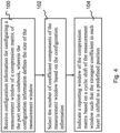
- Figure 4 shows a flowchart of an example for operation of a device receiving and using the configuration information, for example the device 10 of Figure 1 .
- a precoding matrix indicator for a channel state information report configured with a port selection codebook is provided such configuration information for configuring a measurement window of a compression matrix of the port selection codebook, the configuration information defining the size of the measurement window, is received at 100.
- the device can then select the number of components of the measurement window based on the configuration information at 102.
- a reporting window of the compression matrix is indicated at 104 based on a cyclic shift of the measurement window, such that the strongest component in each layer is shifted to a predefined component position. According to an example the strongest component is shifted to the component of index 0.
- FIG. 7 A more detailed example of sending layer specific indications of the initial position is shown in Figure 7 .
- the reporting window is configured as an extension of the measurement window.
- An example of this is shown in Figure 8 where the extension is fixed without need to report an indication of the reporting window.
- the operation in block 104 of Figure 4 would comprise use of a received configuration of a reporting window defining an extension of the measurement window such that the frequency domain component of the strongest coefficient in each layer is shifted to a predefined component position. For example, the strongest component is shifted to the component position of index 0.
- Figure 5 shows a flowchart of an example for operation at a device provided in an access network, for example the access point 12 of Figure 1 , for configuring a device for signalling information in relation to multichannel communications.
- the device sends at 200 configuration information for configuring a measurement window of a compression matrix of a port selection codebook.
- the configuration information defines the number of frequency domain coefficient components of the measurement window.
- a channel state information report including the precoding matrix indicator is then received 202.
- a reporting window of a port selection codebook is received based on a cyclic shift of the measurement window such that the frequency domain component of the strongest coefficient in each layer is shifted to a predefined component, for example the component of index 0.
- the device can then reconstruct precoders based on the precoding matrix indicator at 204.
- the reporting window is configured as an extension of the measurement window.
- An example of this is shown in Figure 8 .
- Figure 6 shows a signalling flowchart in accordance with an example between two communication devices, and more particularly between an UE 10 and a gNB 12, for port selection codebook configuration, measurement and reporting where a specific window size is communicated to the UE. More particularly, the gNB 12 sends message 60 to the UE, the message including a higher layer configuration including a window side parameter N to restrict the selection of M v vectors.
- the configuration is shown to comprises element ⁇ CodebookConfig-r17'.
- the UE can respond with a sounding reference signal (SRS) 61 whereafter the gNB can determine at 62 a set of CSI-RS vector pairs, in spatial and frequency domains.
- SRS sounding reference signal
- the gNB can exploit partial UL-DL reciprocity e.g. as explained above.
- Each CSI-RS port is then precoded at 63 across transmission (tx) antennas and frequency units with a precoder vector pair.
- the precoded CSI-RS is communicate to the UE by message 64.
- the UE can now calculate at 65 CSI report quantities configured e.g. in 'CSI-ReportConfig' including the PMI.
- the PMI reported by message 66 can include one index per layer associated with the selected M v vectors.
- the gNB can then combine at 67 the received PMI with the CSI-RS precoder vector pairs determined at 62 to obtain the precoder for the Physical Downlink Shared Channel (PDSCH) and Demodulation Reference Signal (DMRS). Precoded data and the DMRS can then be signalled to the UE at 68.
- PDSCH Physical Downlink Shared Channel
- DMRS Demodulation Reference Signal
- an enhanced codebook arrangement for signalling port selection channel state information where UE reports a Precoding Matrix Indicator (PMI) in a channel state information (CSI) report configured with port selection codebook in which M v DFT-based vectors of W f are restricted in a configured measurement window of size N and the strongest coefficient in each layer is expected to be located in the first column of the bitmap of the reported nonzero coefficients of W 2 .
- the gNB can then reconstruct the precoders from the PMI.
- One or more indices of the PMI are associated to a reporting window for W f , which can be different from the configured measurement window.
- compression operations can be moved, at least partially or in most part, from the UE to the gNB.
- the enhancement is based on assumption of partial reciprocity of cluster delays in the UL and DL channels and flexibility in use of frequency domain components.
- FIG. 7 A first example is illustrated in Figure 7 .
- the M v -1 nonzero components, if reported, are indicated with respect to the reporting window.
- the index can correspond to the cyclic shift needed to move the component of the strongest coefficient to a predefined component, preferably 0.
- the measurement window configured by the gNB restricts the selection of the M v vectors of W f and is layer common.
- the reporting window can be a layer-specific shifted version of the layer common measurement window.
- the reporting window can be obtained based on the configured measurement window by applying the cyclic shift such that the component of the strongest coefficient is moved to component 0 and an index is then reported to the gNB indicating the shift for each layer.
- the M v components can be configured to be consecutive.
- the index associated to the reporting window can correspond to the component of the strongest coefficient inside the configured measurement window.
- a cyclic shift of -index (“a cyclic shift to the left of index”) can be applied modulo M v by the UE to the columns of the W 2 , before reporting, including the bitmap of reported nonzero coefficients and the corresponding indices of the amplitudes and phases of these nonzero coefficients, such that the strongest coefficient is moved to the first column.
- the UE can be configured not to report M v - 1 nonzero components.
- a cyclic shift of a negative integer value, denoted as -index above, applied to a component x modulo y is a circular shift to the left, i.e. it subtracts index from x and is expressed by the operation: (x-index) mod y.
- a cyclic shift of a positive integer value, index is expressed by the operation: (x+index) mod y.
- the reporting window can be obtained from the configured measurement window by extending the measurement window on one side with additional N - 1 consecutive components. As above, M v - 1 nonzero components, if reported, are indicated with respect to the reporting window.
- the UE may selectively use a reporting window that corresponds the measurement window.
- a UE can be configured to be capable of determining if the strongest tap on any of the layers is on a different component that the first component and in response thereto selectively apply changes to the reporting window from the measurement window. If needed, the UE may selectively indicate the changes to the gNB.
- Figures 9 , 10 and 11 relate to an example where the measurement window size and position as such is kept. Instead, the UE takes another action in view of the strongest components, as will be explained in more detail later in his specification.
- examples of Figures 7 and 8 enable reporting of a binary index per layer.
- This index, index l is equal to f l ⁇ , and hence it may be reported as a column index of the strongest coefficient indicator. No additional reporting of W f may be necessary if the components are configured to be consecutive.
- W 2 is a K 1 ⁇ M v matrix of complex coefficients for each layer where only nonzero combination coefficients are reported.
- the components of W f if reported, are reported with reference to the component of lowest index, instead of the component of the strongest coefficient, such that the M v - 1 reported components are always guaranteed to be within the measurement window of size N configured by the gNB.
- the UE can apply a cyclic shift to the components of W f equal to the index of the first component, ⁇ n 3 , l 0 , instead of ⁇ n 3 , l f l ⁇ as would be the case in Rel-16.
- the gNB in reconstructing the PMI, may apply an opposite cyclic shift, index l , to the columns of the reconstructed W 2 such that they correspond one-to-one to the components of W f in ascending order of index: the first column of W 2 , after the shift index l , corresponds to component of index 0, the second column of W f to the component of lowest index amongst the M v -1 reported component (i.e., to the first reported component), etc., until the last column of W f corresponding to the last of the M v -1 reported components.
- the gNB may obtain the components of W f for layer l after applying the cyclic shift: n 3 , l f ⁇ n 3 , l index l mod N 3 . In this case, the gNB would apply the reconstructed W 2 without cyclic shifts.
- M initial , l R is indicated by means of an index i 1,5, l with value set i 1,5 , l ⁇ 0,1 , ... , N ⁇ 1 and n 3
- l is indicated by a combinatorial index i 1,6, l with value set i 1,6 , l ⁇ 0,1 , ... , N ⁇ 1 M ⁇ ⁇ 1 ⁇ 1 .
- the UE can also report ⁇ M initial , l R ⁇ 0,1 , ... , N ⁇ 1 , for layer l using ⁇ log 2 N ⁇ bits.
- the UE reports the position of the strongest coefficient of layer l by means of i l ⁇ , with i l ⁇ ⁇ 0,1 , ... , K 1 ⁇ 1 using ⁇ log 2 K 1 ⁇ bits.
- N M v > 2
- the first example requires fewer bits than the second example.
- ⁇ log 2 M ⁇ ⁇ bits are needed per layer.
- N M v
- Such a configuration will have a positive effect on UL overhead reduction since no additional information on W f needs to be fed back by the UE other than this layer-specific index.
- This configuration refers to the M v components of W f being configured to be consecutive within the window of size N.
- Figures 9 , 10 and 11 relate to an aspect where no change as such is applied to the size and position of a reporting window in relation to the measurement window configuration. Instead, the reported strongest component can be indicated such that it can be in a different position from the first column.
- a device receives at 300 configuration information for configuring a measurement window of a compression matrix of the port selection codebook, the configuration information defining the size of the measurement window. The device then selects at 302 the number of coefficient components of the measurement window based on the configuration information. When reporting, the device indicates at 304 row and column index of the position of the strongest coefficient components in a matrix of nonzero combination coefficients for each layer and applies a cyclic shift to the columns of the matrix of nonzero combination coefficients for each layer such that the strongest coefficient is shifted to the first column.
- the flowchart of Figure 10 relates to operation at a network device receiving the report.
- the device sends at 400 configuration information for configuring a measurement window of a compression matrix of a port selection codebook, the configuration information defining the number of components of the measurement window.
- CSI report including PMI is then received at 402.
- a row and column index is indicated for the position of the strongest coefficient in a matrix of nonzero combination coefficients for each layer and a cyclic shift is applied to the columns of the matrix of nonzero combination coefficients for each layer such that the first column is shifted to the indicated column index.
- the UE may report W f with respect to the first component rather than the component of the strongest coefficient.
- a layer-specific M initial is not necessary because there is no out-of-window components.
- the UE can still apply the shift ⁇ f l ⁇ relative to the strongest coefficient to W 2 and then report the value of this shift as a part of the strongest coefficient indicator.
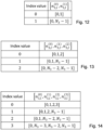
- W f is not aligned with W 2 but because gNB knows f l ⁇ , it can correct the shift on Wf (See Figs. 12-14 ) or undo the shift on W 2 (See Figs. 15-17 ). Either way, the gNB can align W f and W 2 because of the additional reporting of the column index of the strongest coefficient.
- the layer specific W f can be reported for each layer, and can comprise M v -1 components (component 0 is always there and does not need reporting).
- the UE reports the position of the strongest coefficient of layer l by means of i l ⁇ , f l ⁇ , with i l ⁇ ⁇ ⁇ 0,1, ..., K 1 - 1 ⁇ and f l ⁇ ⁇ 0,1 , ... , M ⁇ ⁇ 1 using ⁇ log 2 K 1 M ⁇ ⁇ bits (or ⁇ log 2 K 1 ⁇ + ⁇ log 2 M ⁇ ⁇ bits).
- Figures 12 to 17 show index mappings for N values 2, 3 and 4. Alignment of the indices of W2 and Wf can be done by shifting to indices of W2 (examples in fig. 15-17 ) or shifting to indices of Wf (examples in fig. 12-14 ).
- the flow chart in Fg. 10 relates to the gNB shift on W 2 .
- the first row of the table corresponds to layer 2 (B) of Fig. 7
- the second row corresponds to layer 1 (A) of Fig. 7
- N 3 denotes the number of PMI sub-bands and equals 13 in Figure 7 .
- a communication device for example a user equipment, can comprise means for reporting a PMI in a CSI report configured with port selection codebook in which the M v DFT-based vectors of W f are restricted in a configured measurement window of size N and the strongest coefficient in each layer is expected to be located in the first column of the bitmap of the reported nonzero coefficients of W 2 .
- a network device for example an gNB, can comprise means for reconstructing the precoders from the PMI.
- One or more indices of the PMI ca be associated to a reporting window for W f , which can be different from the configured measurement window.
- the reporting window may also be common for all layers.
- the M v components may be configured to be consecutive and the index associated to the reporting window correspond to the component of the strongest coefficient inside the configured measurement window.
- a cyclic shift of -index can be applied by the UE to the columns of the W 2 , before reporting, including the bitmap of reported nonzero coefficients and the matrices of amplitudes and phases of these nonzero coefficients, such that the strongest coefficient is moved to the first column. In this case the M v - 1 nonzero components may not be reported.
- the SCI needs to be modified by adding information related to the FD component of the strongest coefficient, i.e., either n 3 , l f l ⁇ or f l ⁇ .
- the measurement window for W f restricts the maximum separation between the selected components.
- n 3 f FD (frequency domain) component indices and to f as column index of the matrix of nonzero combination coefficients.
- both coordinates i l ⁇ f l ⁇ of the strongest coefficient need to be reported for each layer l to be able to locate the strongest coefficient, where i l ⁇ ⁇ 0,1 , ... , K 1 ⁇ 1 indicates the row of the matrix of nonzero combination coefficient (which corresponds to one of the K 1 selected CSI-RS ports) and f l ⁇ ⁇ 0,1 , ... , M ⁇ ⁇ 1 indicates the column of the matrix of nonzero combination coefficients.
- This operation is similar to what is done in Rel-16, except for the modulo-N operation, which in Rel-16 is modulo- N 3 , because there is no gNB-defined measurement window for W f in Rel-16.
- the formula also assumes that the FD bases n 3 f (i.e. the codebook indices of the vector components of the compression matrix W f ) are layer-common, i.e., a single set is reported for all layers. However, the operation is also applicable in case of layer-specific W f .
- This alternative does not require a modulo-N operation.
- the result of the demapping at the gNB is the same as if the remapping at the UE was done with respect to first basis, n 3 0 .
- This choice of shift for W f in Rel-16 allows to reduce overhead in the reporting of W f as well as in the reporting of the SCI because only the first coordinate of the pair i l ⁇ f l ⁇ identifying the position of the strongest coefficient for layer l needs reporting.
- W f there are two possible components that can be taken as reference for W f : the component of the strongest coefficient as in Rel-16, or the 'first' selected component, i.e., the component with the lowest index value in the window: ⁇ 0,1 ..., N - 1 ⁇ .
- the following mapping choices are available for W f
- reporting of the pair i l ⁇ f l ⁇ as SCI for layer l is enough to locate the strongest coefficient of W 2 and to ensure correct reconstruction of W f .
- Reporting the values i l ⁇ n 3 f l ⁇ also works but requires more feedback bits if N > M v because n 3 f l ⁇ ⁇ 0,1 , ... , N ⁇ 1 , whereas f l ⁇ ⁇ 0,1 , ... , M ⁇ ⁇ 1 .
- Case 1.a On the left-hand side the UE and gNB operations are shown in the case 1.a, wherein the strongest coefficient for each layer is shifted to FD component 0 and the shift applied to W f follows that of layer 1.
- Case 1.b is shown on the right-hand side, wherein the strongest coefficient is not shifted and the shift applied to W f is with respect to the selected component of lowest index.
- Figure 19 shows a method for the reporting device, such as for a user equipment, following the principles described above, e.g. in Figure 18 .
- the method may be for providing a channel state information report configured with a port selection codebook.
- the method may comprise, in step 1900, receiving configuration information for configuring a measurement window of a compression matrix of the port selection codebook, wherein the configuration information defines the size of the measurement window.
- the size of the measurement window N is larger than number M v of codebook indexes the device is allowed to select for defining the compression matrix W f .
- step 1902 the UE selects a number of codebook indices of the measurement window based on the configuration information to form the compression matrix W f of the port selection codebook, where the codebook indices are associated to vector components of the compression matrix.
- the UE indicates row and column index of the position of the strongest coefficient in a matrix W 2 of nonzero combination coefficients for the layers.
- This step may comprise remapping the columns of the matrix W 2 of nonzero combination coefficients for the layers such that the strongest coefficient is remapped to the first column.
- the UE remaps the codebook indices, such that the codebook index corresponding to the column index of the predefined coefficient of the first layer is remapped to the first index of the measurement window. Remapping may be also called cyclic shifting.
- the predefined coefficient is the strongest coefficient.
- the predefined coefficient is the first coefficient.
- this step may comprise reporting all the codebook indices of the compression matrix of the port selection codebook, except the first, after subtracting the codebook index corresponding to the column index of the strongest coefficient of the first layer from all the codebook indices of the compression matrix and applying a modulo operation of the size of the measurement window N.
- the codebook indices of the measurement window and the compression matrix are DFT vectors.
- Figure 20 shows a method for the device receiving the report, such as for a gNB, following the principles described above, e.g. in Figure 18 .
- the gNB sends configuration information for configuring a measurement window of a compression matrix W f of a port selection codebook, wherein the configuration information defines the number N of components of the measurement window.
- the size of the measurement window N is larger than number M v of codebook indexes the UE is allowed to select for defining the compression matrix W f .
- the gNB receives a channel state information report including a precoding matrix indicator (PM), wherein row and column indices are indicated for the positions of the strongest coefficients in layers of a matrix W 2 of nonzero combination coefficients, and the PMI comprises codebook indices of a compression matrix W f .
- PM precoding matrix indicator
- these indices have been remapped at the transmitter side as described above, e.g. with respect to the strongest coefficient being shifted to the first index.
- the gNB demaps the codebook indices of the compression matrix W f with respect to one of the codebook indices whose position is a function of the column index of the predefined coefficient of the first layer and the number of components of the compression matrix.
- the predefined coefficient is the strongest coefficient. This takes place when it is detected that the column index of the strongest coefficient of the first layer is nonzero.
- This step 2004 may comprise that the demapping of the codebook indices of the compression matrix comprises subtracting one of the codebook indices from all the codebook indices of the compression matrix W f and applying a modulo operation of the size N of the measurement window.
- the function identifying the position of the one codebook index is obtained by subtracting the nonzero column index of the strongest coefficient of the first layer from the number M v of components of the compression matrix W f .
- the matrix W 2 of nonzero combination coefficients and compression matrix W f of the codebook are aligned based on the indicated column indices of the strongest coefficients.
- step 2006 the gNB constructs precoders based on the received channel state information report.
- the solutions are applicable to layer specific W f as well.
- the compression matrix W f of the port selection codebook for each layer is remapped with respect to the codebook index corresponding to the column index of the strongest coefficient of the respective layer.
- some embodiments may be implemented in hardware or special purpose circuits, software, logic or any combination thereof.
- some aspects may be implemented in hardware, while other aspects may be implemented in firmware or software which may be executed by a controller, microprocessor or other computing device, although embodiments are not limited thereto.
- firmware or software which may be executed by a controller, microprocessor or other computing device, although embodiments are not limited thereto. While various embodiments may be illustrated and described as block diagrams, flow charts, or using some other pictorial representation, it is well understood that these blocks, apparatus, systems, techniques or methods described herein may be implemented in, as non-limiting examples, hardware, software, firmware, special purpose circuits or logic, general purpose hardware or controller or other computing devices, or some combination thereof.
- the embodiments may be implemented by computer software stored in a memory and executable by at least one data processor of the involved entities or by hardware, or by a combination of software and hardware. Further in this regard it should be noted that any of the above procedures may represent program steps, or interconnected logic circuits, blocks and functions, or a combination of program steps and logic circuits, blocks and functions.
- the software may be stored on such physical media as memory chips, or memory blocks implemented within the processor, magnetic media such as hard disk or floppy disks, and optical media such as for example DVD and the data variants thereof, CD.
- the memory may be of any type suitable to the local technical environment and may be implemented using any suitable data storage technology, such as semiconductor based memory devices, magnetic memory devices and systems, optical memory devices and systems, fixed memory and removable memory.
- the data processors may be of any type suitable to the local technical environment, and may include one or more of general purpose computers, special purpose computers, microprocessors, digital signal processors (DSPs), application specific integrated circuits (ASIC), gate level circuits and processors based on multi core processor architecture, as non-limiting examples.
- circuitry may be configured to perform one or more of the functions and/or method procedures previously described. That circuitry may be provided in the network entity and/or in the communications device and/or a server and/or a device.
- circuitry may refer to one or more or all of the following:
- circuitry also covers an implementation of merely a hardware circuit or processor (or multiple processors) or portion of a hardware circuit or processor and its (or their) accompanying software and/or firmware.
- circuitry also covers, for example integrated device.
Landscapes
- Engineering & Computer Science (AREA)
- Computer Networks & Wireless Communication (AREA)
- Signal Processing (AREA)
- Physics & Mathematics (AREA)
- Mathematical Physics (AREA)
- Mobile Radio Communication Systems (AREA)
- Compression, Expansion, Code Conversion, And Decoders (AREA)
- Data Exchanges In Wide-Area Networks (AREA)
- Holo Graphy (AREA)
- Apparatus For Radiation Diagnosis (AREA)
- Forging (AREA)
Claims (15)
- Appareil, comprenant des moyens pour :recevoir, d'un ensemble de livres de codes de composantes vectorielles, des informations de configuration pour configurer une fenêtre de mesure afin de former une matrice de compression d'un livre de codes de sélection de port, dans lequel les informations de configuration définissent la taille de la fenêtre de mesure qui est commune à la totalité d'une ou plusieurs couches à rapporter ;sélectionner, dans l'ensemble de livres de codes de composantes vectorielles, un certain nombre d'index de la fenêtre de mesure sur la base des informations de configuration afin de former la matrice de compression, dans lequel les index sélectionnés sont associés aux composantes vectorielles de la matrice de compression et sont communs à la totalité des une ou plusieurs couches à rapporter ; etremapper les index sélectionnés associés aux composantes vectorielles par rapport à un index d'une composante vectorielle de référence, de sorte que l'index de la composante vectorielle de référence soit remappé à un premier index de la fenêtre de mesure ;rapporter des informations d'état de canal comportant un indicateur de matrice de pré-codage à un réseau, l'indicateur de matrice de pré-codage comprenant des informations de la matrice de compression après remappage.
- Appareil de la revendication 1, dans lequel les informations de configuration configurent en outre un certain nombre de composantes vectorielles de la matrice de compression.
- Appareil de la revendication 2, dans lequel le nombre de composantes vectorielles de la matrice de compression est inférieur au nombre d'index dans la fenêtre de mesure.
- Appareil de l'une des revendications 1 à 3, où l'index de la composante vectorielle de référence est le plus faible parmi les index sélectionnés, et le premier index de la fenêtre de mesure est 0.
- Appareil de l'une des revendications 1 à 4, où le remappage comprend la soustraction de l'index de la composante de référence de tous les index de la matrice de compression.
- Appareil de l'une des revendications 1 à 5, dans lequel l'indicateur de matrice de pré-codage indique tous les index de la matrice de compression, à l'exception du premier, après remappage.
- Appareil de l'une des revendications 1 à 6, dans lequel les moyens sont en outre configurés pour effectuer :la détermination d'une position d'un coefficient le plus fort dans une matrice de coefficients de combinaison non nuls pour chacune des une ou plusieurs couches rapportées ; etl'indication d'un index de ligne et de colonne de la position du coefficient le plus fort dans la matrice des coefficients de combinaison non nuls pour chacune des une ou plusieurs couches rapportées.
- Appareil de l'une des revendications 1 à 7, dans lequel les une ou plusieurs couches à rapporter comprennent une pluralité de couches.
- Appareil comprenant :au moins un processeur et au moins une mémoire comportant un code de programme informatique, dans lequel l'au moins une mémoire et le code de programme informatique sont configurés, avec l'au moins un processeur, pour amener l'appareil à effectuer :l'envoi d'informations de configuration pour configurer une fenêtre de mesure afin de former une matrice de compression d'un livre de codes de sélection de port à partir d'un ensemble de livres de codes de composantes vectorielles, dans lequel les informations de configuration définissent le nombre de composantes de la fenêtre de mesure qui est commune à la totalité d'une ou plusieurs couches à rapporter ;la réception d'un rapport d'informations d'état de canal comportant un indicateur de matrice de pré-codage comprenant des informations d'une matrice de compression d'un livre de codes de sélection de port après remappage, dans lequel au cours du remappage, des index sélectionnés de la fenêtre de mesure ont été remappés par rapport à l'index d'une composante vectorielle de référence, l'index de la composante vectorielle de référence ayant ainsi été remappé à un premier index de la fenêtre de mesure, dans lequel les index sélectionnés sont associés aux composantes vectorielles de la matrice de compression et sont communs à la totalité des une ou plusieurs couches rapportées ; etla reconstruction des pré-codeurs sur la base de l'indicateur de matrice de pré-codage.
- Appareil de la revendication 9, dans lequel les informations de configuration configurent en outre un certain nombre de composantes vectorielles de la matrice de compression.
- Appareil de l'une des revendications 9 et 10, dans lequel l'indicateur de matrice de pré-codage comprend en outre des informations indiquant des index de ligne et de colonne de la position d'un coefficient le plus fort dans une matrice de coefficients de combinaison non nuls pour chacune des une ou plusieurs couches rapportées.
- Procédé, comprenant :la réception, d'un ensemble de livres de codes de composantes vectorielles, d'informations de configuration pour configurer une fenêtre de mesure afin de former une matrice de compression d'un livre de codes de sélection de port, dans lequel les informations de configuration définissent la taille de la fenêtre de mesure qui est commune à la totalité d'une ou plusieurs couches à rapporter ;la sélection, dans l'ensemble de livres de codes de composantes vectorielles, d'un certain nombre d'index de la fenêtre de mesure sur la base des informations de configuration afin de former la matrice de compression, dans lequel les index sélectionnés sont associés aux composantes vectorielles de la matrice de compression et sont communs à la totalité des une ou plusieurs couches à rapporter ; etle remappage des index sélectionnés associés aux composantes vectorielles par rapport à un index d'une composante vectorielle de référence, de sorte que l'index de la composante vectorielle de référence soit remappé à un premier index de la fenêtre de mesure ;l'établissement d'un rapport d'informations d'état de canal comportant un indicateur de matrice de pré-codage à un réseau, l'indicateur de matrice de pré-codage comprenant des informations de la matrice de compression après remappage.
- Procédé, comprenant :l'envoi d'informations de configuration pour configurer une fenêtre de mesure afin de former une matrice de compression d'un livre de codes de sélection de port à partir d'un ensemble de livres de codes de composantes vectorielles, dans lequel les informations de configuration définissent le nombre de composantes de la fenêtre de mesure qui est commune à la totalité d'une ou plusieurs couches à rapporter ;la réception d'un rapport d'informations d'état de canal comportant un indicateur de matrice de pré-codage comprenant des informations d'une matrice de compression d'un livre de codes de sélection de port après remappage, dans lequel au cours du remappage, des index sélectionnés de la fenêtre de mesure ont été remappés par rapport à l'index d'une composante vectorielle de référence, l'index de la composante vectorielle de référence ayant ainsi été remappé à un premier index de la fenêtre de mesure, dans lequel les index sélectionnés sont associés aux composantes vectorielles de la matrice de compression et sont communs à la totalité des une ou plusieurs couches rapportées ; etla reconstruction de pré-codeurs sur la base de l'indicateur de matrice de pré-codage.
- Produit de programme informatique incorporé dans un support de distribution lisible par un ordinateur et comprenant des instructions de programme qui, lorsqu'elles sont exécutées par un appareil, amènent l'appareil à mettre en oeuvre le procédé selon l'une des revendications 12 et 13.
- Produit de programme informatique comprenant des instructions de programme qui, lorsqu'elles sont exécutées par un appareil, amènent l'appareil à mettre en oeuvre le procédé selon l'une des revendications 12 et 13.
Applications Claiming Priority (2)
| Application Number | Priority Date | Filing Date | Title |
|---|---|---|---|
| US202163187347P | 2021-05-11 | 2021-05-11 | |
| US202163230349P | 2021-08-06 | 2021-08-06 |
Publications (2)
| Publication Number | Publication Date |
|---|---|
| EP4092922A1 EP4092922A1 (fr) | 2022-11-23 |
| EP4092922B1 true EP4092922B1 (fr) | 2023-12-13 |
Family
ID=81393067
Family Applications (2)
| Application Number | Title | Priority Date | Filing Date |
|---|---|---|---|
| EP22806897.9A Pending EP4338302A4 (fr) | 2021-05-11 | 2022-04-28 | Informations de précodage |
| EP22170400.0A Active EP4092922B1 (fr) | 2021-05-11 | 2022-04-28 | Précodage d'informations |
Family Applications Before (1)
| Application Number | Title | Priority Date | Filing Date |
|---|---|---|---|
| EP22806897.9A Pending EP4338302A4 (fr) | 2021-05-11 | 2022-04-28 | Informations de précodage |
Country Status (13)
| Country | Link |
|---|---|
| EP (2) | EP4338302A4 (fr) |
| JP (1) | JP7644267B2 (fr) |
| KR (1) | KR102881909B1 (fr) |
| AU (1) | AU2022273916B2 (fr) |
| CA (1) | CA3218276A1 (fr) |
| CL (2) | CL2023003368A1 (fr) |
| CO (1) | CO2023017058A2 (fr) |
| ES (1) | ES2970144T3 (fr) |
| FI (1) | FI4092922T3 (fr) |
| MA (1) | MA71361A (fr) |
| MX (1) | MX2023013242A (fr) |
| PL (1) | PL4092922T3 (fr) |
| WO (1) | WO2022238612A1 (fr) |
Families Citing this family (4)
| Publication number | Priority date | Publication date | Assignee | Title |
|---|---|---|---|---|
| CN118119010A (zh) * | 2022-11-30 | 2024-05-31 | 华为技术有限公司 | 通信方法及装置 |
| CN118174755A (zh) * | 2022-12-09 | 2024-06-11 | 哲库科技(北京)有限公司 | 频域压缩方法及装置 |
| WO2024156073A1 (fr) * | 2023-01-25 | 2024-08-02 | Qualcomm Incorporated | Rapport de paramètres pour de multiples sous-bandes |
| CN118802025A (zh) * | 2023-04-13 | 2024-10-18 | 中兴通讯股份有限公司 | 监测方法及装置 |
Family Cites Families (5)
| Publication number | Priority date | Publication date | Assignee | Title |
|---|---|---|---|---|
| EP3474459A1 (fr) * | 2017-10-18 | 2019-04-24 | Fraunhofer-Gesellschaft zur Förderung der angewandten Forschung e.V. | Récepteur, émetteur, système et procédé employant un précodage de temporisation spatiale |
| EP3734852A1 (fr) * | 2019-05-02 | 2020-11-04 | Fraunhofer Gesellschaft zur Förderung der angewandten Forschung e.V. | Procédés et appareils de reporting csi dans un système de communication sans fil |
| US11463142B2 (en) | 2019-09-06 | 2022-10-04 | Samsung Electronics Co., Ltd. | Method and apparatus for uplink control information omission |
| KR20260049306A (ko) * | 2019-10-29 | 2026-04-13 | 노키아 테크놀로지스 오와이 | Pmi 보고 및 사용을 위한 조합 인디케이터에 대한 윈도우 fd 기반의 매핑 |
| BR112023021175A2 (pt) | 2021-04-12 | 2023-12-19 | Lenovo Singapore Pte Ltd | Relatórios de csi com subconjunto de indicadores de coeficiente |
-
2022
- 2022-04-28 PL PL22170400.0T patent/PL4092922T3/pl unknown
- 2022-04-28 WO PCT/FI2022/050277 patent/WO2022238612A1/fr not_active Ceased
- 2022-04-28 FI FIEP22170400.0T patent/FI4092922T3/fi active
- 2022-04-28 MA MA71361A patent/MA71361A/fr unknown
- 2022-04-28 KR KR1020237042501A patent/KR102881909B1/ko active Active
- 2022-04-28 AU AU2022273916A patent/AU2022273916B2/en active Active
- 2022-04-28 CA CA3218276A patent/CA3218276A1/fr active Pending
- 2022-04-28 EP EP22806897.9A patent/EP4338302A4/fr active Pending
- 2022-04-28 EP EP22170400.0A patent/EP4092922B1/fr active Active
- 2022-04-28 MX MX2023013242A patent/MX2023013242A/es unknown
- 2022-04-28 JP JP2023570051A patent/JP7644267B2/ja active Active
- 2022-04-28 ES ES22170400T patent/ES2970144T3/es active Active
-
2023
- 2023-11-10 CL CL2023003368A patent/CL2023003368A1/es unknown
- 2023-12-07 CO CONC2023/0017058A patent/CO2023017058A2/es unknown
-
2024
- 2024-10-21 CL CL2024003215A patent/CL2024003215A1/es unknown
Also Published As
| Publication number | Publication date |
|---|---|
| JP7644267B2 (ja) | 2025-03-11 |
| CL2023003368A1 (es) | 2024-05-17 |
| EP4092922A1 (fr) | 2022-11-23 |
| WO2022238612A1 (fr) | 2022-11-17 |
| EP4338302A4 (fr) | 2025-05-14 |
| JP2024519341A (ja) | 2024-05-10 |
| AU2022273916A1 (en) | 2023-12-07 |
| AU2022273916B2 (en) | 2025-01-23 |
| CA3218276A1 (fr) | 2022-11-17 |
| EP4338302A1 (fr) | 2024-03-20 |
| KR20240006640A (ko) | 2024-01-15 |
| CO2023017058A2 (es) | 2023-12-29 |
| MA71361A (fr) | 2025-04-30 |
| CL2024003215A1 (es) | 2025-02-21 |
| KR102881909B1 (ko) | 2025-11-05 |
| FI4092922T3 (fi) | 2024-01-11 |
| MX2023013242A (es) | 2023-12-15 |
| ES2970144T3 (es) | 2024-05-27 |
| PL4092922T3 (pl) | 2024-03-18 |
Similar Documents
| Publication | Publication Date | Title |
|---|---|---|
| EP4092922B1 (fr) | Précodage d'informations | |
| US10419090B2 (en) | Method for precoding matrix indicator feedback and apparatus | |
| EP2901568B1 (fr) | Retour d'informations d'état de canal non basé sur des livres de codes | |
| CN108616299B (zh) | 确定预编码矩阵指示的方法、用户设备和基站 | |
| US20250317183A1 (en) | Signalling port information | |
| US20250141524A1 (en) | Reporting channel state information (csi) precoding matrix indicator (pmi) | |
| CN112311431B (zh) | 一种空频合并系数的指示方法及装置 | |
| US12244372B2 (en) | Methods and apparatus for port selection codebook enhancement | |
| CN110336597A (zh) | 确定预编码矩阵指示的方法、用户设备和基站 | |
| CN117203905A (zh) | 为端口选择码本增强配置W1、W2和Wf的方法和装置 | |
| WO2017167156A1 (fr) | Procédé et dispositif de transmission de dmrs | |
| CN108282255A (zh) | 参数取值的确定、配置方法及装置、终端及基站 | |
| WO2017148429A1 (fr) | Procédé et appareil de transmission de données | |
| CN114389778B (zh) | 用信号发送端口信息 | |
| US20260051928A1 (en) | Codebook report design to support dynamic multi-trp coherent joint transmission operation | |
| CN115189837B (zh) | 端口指示信息上报方法及终端 | |
| WO2025140998A1 (fr) | Rapport d'informations d'état de canal pour mise à l'échelle du coefficient de précodage dans des communications sans fil | |
| CN117042179A (zh) | Csi上报的方法、终端、网络设备、装置及存储介质 |
Legal Events
| Date | Code | Title | Description |
|---|---|---|---|
| PUAI | Public reference made under article 153(3) epc to a published international application that has entered the european phase |
Free format text: ORIGINAL CODE: 0009012 |
|
| STAA | Information on the status of an ep patent application or granted ep patent |
Free format text: STATUS: THE APPLICATION HAS BEEN PUBLISHED |
|
| AK | Designated contracting states |
Kind code of ref document: A1 Designated state(s): AL AT BE BG CH CY CZ DE DK EE ES FI FR GB GR HR HU IE IS IT LI LT LU LV MC MK MT NL NO PL PT RO RS SE SI SK SM TR |
|
| STAA | Information on the status of an ep patent application or granted ep patent |
Free format text: STATUS: REQUEST FOR EXAMINATION WAS MADE |
|
| 17P | Request for examination filed |
Effective date: 20230523 |
|
| GRAP | Despatch of communication of intention to grant a patent |
Free format text: ORIGINAL CODE: EPIDOSNIGR1 |
|
| RBV | Designated contracting states (corrected) |
Designated state(s): AL AT BE BG CH CY CZ DE DK EE ES FI FR GB GR HR HU IE IS IT LI LT LU LV MC MK MT NL NO PL PT RO RS SE SI SK SM TR |
|
| STAA | Information on the status of an ep patent application or granted ep patent |
Free format text: STATUS: GRANT OF PATENT IS INTENDED |
|
| RIC1 | Information provided on ipc code assigned before grant |
Ipc: H04B 7/0456 20170101AFI20230613BHEP |
|
| INTG | Intention to grant announced |
Effective date: 20230629 |
|
| GRAS | Grant fee paid |
Free format text: ORIGINAL CODE: EPIDOSNIGR3 |
|
| GRAA | (expected) grant |
Free format text: ORIGINAL CODE: 0009210 |
|
| STAA | Information on the status of an ep patent application or granted ep patent |
Free format text: STATUS: THE PATENT HAS BEEN GRANTED |
|
| AK | Designated contracting states |
Kind code of ref document: B1 Designated state(s): AL AT BE BG CH CY CZ DE DK EE ES FI FR GB GR HR HU IE IS IT LI LT LU LV MC MK MT NL NO PL PT RO RS SE SI SK SM TR |
|
| REG | Reference to a national code |
Ref country code: GB Ref legal event code: FG4D |
|
| REG | Reference to a national code |
Ref country code: CH Ref legal event code: EP |
|
| REG | Reference to a national code |
Ref country code: DE Ref legal event code: R096 Ref document number: 602022001273 Country of ref document: DE |
|
| REG | Reference to a national code |
Ref country code: IE Ref legal event code: FG4D |
|
| REG | Reference to a national code |
Ref country code: FI Ref legal event code: FGE |
|
| REG | Reference to a national code |
Ref country code: NL Ref legal event code: FP |
|
| REG | Reference to a national code |
Ref country code: SE Ref legal event code: TRGR |
|
| PG25 | Lapsed in a contracting state [announced via postgrant information from national office to epo] |
Ref country code: GR Free format text: LAPSE BECAUSE OF FAILURE TO SUBMIT A TRANSLATION OF THE DESCRIPTION OR TO PAY THE FEE WITHIN THE PRESCRIBED TIME-LIMIT Effective date: 20240314 |
|
| REG | Reference to a national code |
Ref country code: LT Ref legal event code: MG9D |
|
| PG25 | Lapsed in a contracting state [announced via postgrant information from national office to epo] |
Ref country code: LT Free format text: LAPSE BECAUSE OF FAILURE TO SUBMIT A TRANSLATION OF THE DESCRIPTION OR TO PAY THE FEE WITHIN THE PRESCRIBED TIME-LIMIT Effective date: 20231213 |
|
| PG25 | Lapsed in a contracting state [announced via postgrant information from national office to epo] |
Ref country code: LT Free format text: LAPSE BECAUSE OF FAILURE TO SUBMIT A TRANSLATION OF THE DESCRIPTION OR TO PAY THE FEE WITHIN THE PRESCRIBED TIME-LIMIT Effective date: 20231213 Ref country code: GR Free format text: LAPSE BECAUSE OF FAILURE TO SUBMIT A TRANSLATION OF THE DESCRIPTION OR TO PAY THE FEE WITHIN THE PRESCRIBED TIME-LIMIT Effective date: 20240314 Ref country code: BG Free format text: LAPSE BECAUSE OF FAILURE TO SUBMIT A TRANSLATION OF THE DESCRIPTION OR TO PAY THE FEE WITHIN THE PRESCRIBED TIME-LIMIT Effective date: 20240313 |
|
| REG | Reference to a national code |
Ref country code: AT Ref legal event code: MK05 Ref document number: 1641363 Country of ref document: AT Kind code of ref document: T Effective date: 20231213 |
|
| REG | Reference to a national code |
Ref country code: ES Ref legal event code: FG2A Ref document number: 2970144 Country of ref document: ES Kind code of ref document: T3 Effective date: 20240527 |
|
| PG25 | Lapsed in a contracting state [announced via postgrant information from national office to epo] |
Ref country code: RS Free format text: LAPSE BECAUSE OF FAILURE TO SUBMIT A TRANSLATION OF THE DESCRIPTION OR TO PAY THE FEE WITHIN THE PRESCRIBED TIME-LIMIT Effective date: 20231213 Ref country code: NO Free format text: LAPSE BECAUSE OF FAILURE TO SUBMIT A TRANSLATION OF THE DESCRIPTION OR TO PAY THE FEE WITHIN THE PRESCRIBED TIME-LIMIT Effective date: 20240313 Ref country code: LV Free format text: LAPSE BECAUSE OF FAILURE TO SUBMIT A TRANSLATION OF THE DESCRIPTION OR TO PAY THE FEE WITHIN THE PRESCRIBED TIME-LIMIT Effective date: 20231213 Ref country code: HR Free format text: LAPSE BECAUSE OF FAILURE TO SUBMIT A TRANSLATION OF THE DESCRIPTION OR TO PAY THE FEE WITHIN THE PRESCRIBED TIME-LIMIT Effective date: 20231213 |
|
| PG25 | Lapsed in a contracting state [announced via postgrant information from national office to epo] |
Ref country code: IS Free format text: LAPSE BECAUSE OF FAILURE TO SUBMIT A TRANSLATION OF THE DESCRIPTION OR TO PAY THE FEE WITHIN THE PRESCRIBED TIME-LIMIT Effective date: 20240413 |
|
| PG25 | Lapsed in a contracting state [announced via postgrant information from national office to epo] |
Ref country code: CZ Free format text: LAPSE BECAUSE OF FAILURE TO SUBMIT A TRANSLATION OF THE DESCRIPTION OR TO PAY THE FEE WITHIN THE PRESCRIBED TIME-LIMIT Effective date: 20231213 Ref country code: AT Free format text: LAPSE BECAUSE OF FAILURE TO SUBMIT A TRANSLATION OF THE DESCRIPTION OR TO PAY THE FEE WITHIN THE PRESCRIBED TIME-LIMIT Effective date: 20231213 |
|
| PG25 | Lapsed in a contracting state [announced via postgrant information from national office to epo] |
Ref country code: SK Free format text: LAPSE BECAUSE OF FAILURE TO SUBMIT A TRANSLATION OF THE DESCRIPTION OR TO PAY THE FEE WITHIN THE PRESCRIBED TIME-LIMIT Effective date: 20231213 |
|
| PG25 | Lapsed in a contracting state [announced via postgrant information from national office to epo] |
Ref country code: SM Free format text: LAPSE BECAUSE OF FAILURE TO SUBMIT A TRANSLATION OF THE DESCRIPTION OR TO PAY THE FEE WITHIN THE PRESCRIBED TIME-LIMIT Effective date: 20231213 Ref country code: SK Free format text: LAPSE BECAUSE OF FAILURE TO SUBMIT A TRANSLATION OF THE DESCRIPTION OR TO PAY THE FEE WITHIN THE PRESCRIBED TIME-LIMIT Effective date: 20231213 Ref country code: RO Free format text: LAPSE BECAUSE OF FAILURE TO SUBMIT A TRANSLATION OF THE DESCRIPTION OR TO PAY THE FEE WITHIN THE PRESCRIBED TIME-LIMIT Effective date: 20231213 Ref country code: IS Free format text: LAPSE BECAUSE OF FAILURE TO SUBMIT A TRANSLATION OF THE DESCRIPTION OR TO PAY THE FEE WITHIN THE PRESCRIBED TIME-LIMIT Effective date: 20240413 Ref country code: EE Free format text: LAPSE BECAUSE OF FAILURE TO SUBMIT A TRANSLATION OF THE DESCRIPTION OR TO PAY THE FEE WITHIN THE PRESCRIBED TIME-LIMIT Effective date: 20231213 Ref country code: CZ Free format text: LAPSE BECAUSE OF FAILURE TO SUBMIT A TRANSLATION OF THE DESCRIPTION OR TO PAY THE FEE WITHIN THE PRESCRIBED TIME-LIMIT Effective date: 20231213 Ref country code: AT Free format text: LAPSE BECAUSE OF FAILURE TO SUBMIT A TRANSLATION OF THE DESCRIPTION OR TO PAY THE FEE WITHIN THE PRESCRIBED TIME-LIMIT Effective date: 20231213 |
|
| PG25 | Lapsed in a contracting state [announced via postgrant information from national office to epo] |
Ref country code: PT Free format text: LAPSE BECAUSE OF FAILURE TO SUBMIT A TRANSLATION OF THE DESCRIPTION OR TO PAY THE FEE WITHIN THE PRESCRIBED TIME-LIMIT Effective date: 20240415 |
|
| PG25 | Lapsed in a contracting state [announced via postgrant information from national office to epo] |
Ref country code: PT Free format text: LAPSE BECAUSE OF FAILURE TO SUBMIT A TRANSLATION OF THE DESCRIPTION OR TO PAY THE FEE WITHIN THE PRESCRIBED TIME-LIMIT Effective date: 20240415 |
|
| REG | Reference to a national code |
Ref country code: DE Ref legal event code: R097 Ref document number: 602022001273 Country of ref document: DE |
|
| PG25 | Lapsed in a contracting state [announced via postgrant information from national office to epo] |
Ref country code: DK Free format text: LAPSE BECAUSE OF FAILURE TO SUBMIT A TRANSLATION OF THE DESCRIPTION OR TO PAY THE FEE WITHIN THE PRESCRIBED TIME-LIMIT Effective date: 20231213 |
|
| PLBE | No opposition filed within time limit |
Free format text: ORIGINAL CODE: 0009261 |
|
| STAA | Information on the status of an ep patent application or granted ep patent |
Free format text: STATUS: NO OPPOSITION FILED WITHIN TIME LIMIT |
|
| PG25 | Lapsed in a contracting state [announced via postgrant information from national office to epo] |
Ref country code: SI Free format text: LAPSE BECAUSE OF FAILURE TO SUBMIT A TRANSLATION OF THE DESCRIPTION OR TO PAY THE FEE WITHIN THE PRESCRIBED TIME-LIMIT Effective date: 20231213 |
|
| PG25 | Lapsed in a contracting state [announced via postgrant information from national office to epo] |
Ref country code: SI Free format text: LAPSE BECAUSE OF FAILURE TO SUBMIT A TRANSLATION OF THE DESCRIPTION OR TO PAY THE FEE WITHIN THE PRESCRIBED TIME-LIMIT Effective date: 20231213 Ref country code: DK Free format text: LAPSE BECAUSE OF FAILURE TO SUBMIT A TRANSLATION OF THE DESCRIPTION OR TO PAY THE FEE WITHIN THE PRESCRIBED TIME-LIMIT Effective date: 20231213 |
|
| 26N | No opposition filed |
Effective date: 20240916 |
|
| PG25 | Lapsed in a contracting state [announced via postgrant information from national office to epo] |
Ref country code: MC Free format text: LAPSE BECAUSE OF FAILURE TO SUBMIT A TRANSLATION OF THE DESCRIPTION OR TO PAY THE FEE WITHIN THE PRESCRIBED TIME-LIMIT Effective date: 20231213 |
|
| PG25 | Lapsed in a contracting state [announced via postgrant information from national office to epo] |
Ref country code: MC Free format text: LAPSE BECAUSE OF FAILURE TO SUBMIT A TRANSLATION OF THE DESCRIPTION OR TO PAY THE FEE WITHIN THE PRESCRIBED TIME-LIMIT Effective date: 20231213 |
|
| PG25 | Lapsed in a contracting state [announced via postgrant information from national office to epo] |
Ref country code: LU Free format text: LAPSE BECAUSE OF NON-PAYMENT OF DUE FEES Effective date: 20240428 |
|
| PG25 | Lapsed in a contracting state [announced via postgrant information from national office to epo] |
Ref country code: LU Free format text: LAPSE BECAUSE OF NON-PAYMENT OF DUE FEES Effective date: 20240428 |
|
| PGFP | Annual fee paid to national office [announced via postgrant information from national office to epo] |
Ref country code: FI Payment date: 20250421 Year of fee payment: 4 |
|
| PGFP | Annual fee paid to national office [announced via postgrant information from national office to epo] |
Ref country code: DE Payment date: 20250305 Year of fee payment: 4 |
|
| PGFP | Annual fee paid to national office [announced via postgrant information from national office to epo] |
Ref country code: ES Payment date: 20250508 Year of fee payment: 4 |
|
| PGFP | Annual fee paid to national office [announced via postgrant information from national office to epo] |
Ref country code: IT Payment date: 20250430 Year of fee payment: 4 |
|
| PGFP | Annual fee paid to national office [announced via postgrant information from national office to epo] |
Ref country code: CH Payment date: 20250501 Year of fee payment: 4 |
|
| PGFP | Annual fee paid to national office [announced via postgrant information from national office to epo] |
Ref country code: TR Payment date: 20250411 Year of fee payment: 4 |
|
| PG25 | Lapsed in a contracting state [announced via postgrant information from national office to epo] |
Ref country code: CY Free format text: LAPSE BECAUSE OF FAILURE TO SUBMIT A TRANSLATION OF THE DESCRIPTION OR TO PAY THE FEE WITHIN THE PRESCRIBED TIME-LIMIT; INVALID AB INITIO Effective date: 20220428 |
|
| PG25 | Lapsed in a contracting state [announced via postgrant information from national office to epo] |
Ref country code: HU Free format text: LAPSE BECAUSE OF FAILURE TO SUBMIT A TRANSLATION OF THE DESCRIPTION OR TO PAY THE FEE WITHIN THE PRESCRIBED TIME-LIMIT; INVALID AB INITIO Effective date: 20220428 |
|
| PGFP | Annual fee paid to national office [announced via postgrant information from national office to epo] |
Ref country code: SE Payment date: 20260312 Year of fee payment: 5 |
|
| PGFP | Annual fee paid to national office [announced via postgrant information from national office to epo] |
Ref country code: GB Payment date: 20260312 Year of fee payment: 5 |
|
| PGFP | Annual fee paid to national office [announced via postgrant information from national office to epo] |
Ref country code: IE Payment date: 20260310 Year of fee payment: 5 |
|
| PGFP | Annual fee paid to national office [announced via postgrant information from national office to epo] |
Ref country code: BE Payment date: 20260317 Year of fee payment: 5 |
|
| PGFP | Annual fee paid to national office [announced via postgrant information from national office to epo] |
Ref country code: NL Payment date: 20260317 Year of fee payment: 5 |
|
| PGFP | Annual fee paid to national office [announced via postgrant information from national office to epo] |
Ref country code: FR Payment date: 20260309 Year of fee payment: 5 |
|
| PGFP | Annual fee paid to national office [announced via postgrant information from national office to epo] |
Ref country code: PL Payment date: 20260316 Year of fee payment: 5 |