EP4093052A1 - Procédé et dispositif de traitement sélectif en fréquence d'un signal audio à faible latence - Google Patents
Procédé et dispositif de traitement sélectif en fréquence d'un signal audio à faible latence Download PDFInfo
- Publication number
- EP4093052A1 EP4093052A1 EP22168308.9A EP22168308A EP4093052A1 EP 4093052 A1 EP4093052 A1 EP 4093052A1 EP 22168308 A EP22168308 A EP 22168308A EP 4093052 A1 EP4093052 A1 EP 4093052A1
- Authority
- EP
- European Patent Office
- Prior art keywords
- frequency bands
- frequency
- audio signal
- sub
- filter bank
- Prior art date
- Legal status (The legal status is an assumption and is not a legal conclusion. Google has not performed a legal analysis and makes no representation as to the accuracy of the status listed.)
- Withdrawn
Links
Images

Classifications
-
- H—ELECTRICITY
- H04—ELECTRIC COMMUNICATION TECHNIQUE
- H04R—LOUDSPEAKERS, MICROPHONES, GRAMOPHONE PICK-UPS OR LIKE ACOUSTIC ELECTROMECHANICAL TRANSDUCERS; ELECTRIC HEARING AIDS; PUBLIC ADDRESS SYSTEMS
- H04R25/00—Electric hearing aids
- H04R25/35—Electric hearing aids using translation techniques
- H04R25/353—Frequency, e.g. frequency shift or compression
-
- H—ELECTRICITY
- H04—ELECTRIC COMMUNICATION TECHNIQUE
- H04R—LOUDSPEAKERS, MICROPHONES, GRAMOPHONE PICK-UPS OR LIKE ACOUSTIC ELECTROMECHANICAL TRANSDUCERS; ELECTRIC HEARING AIDS; PUBLIC ADDRESS SYSTEMS
- H04R25/00—Electric hearing aids
- H04R25/50—Customised settings for obtaining desired overall acoustical characteristics
- H04R25/505—Customised settings for obtaining desired overall acoustical characteristics using digital signal processing
-
- G—PHYSICS
- G10—MUSICAL INSTRUMENTS; ACOUSTICS
- G10L—SPEECH ANALYSIS TECHNIQUES OR SPEECH SYNTHESIS; SPEECH RECOGNITION; SPEECH OR VOICE PROCESSING TECHNIQUES; SPEECH OR AUDIO CODING OR DECODING
- G10L21/00—Speech or voice signal processing techniques to produce another audible or non-audible signal, e.g. visual or tactile, in order to modify its quality or its intelligibility
- G10L21/02—Speech enhancement, e.g. noise reduction or echo cancellation
- G10L21/0208—Noise filtering
- G10L21/0216—Noise filtering characterised by the method used for estimating noise
- G10L21/0232—Processing in the frequency domain
-
- H—ELECTRICITY
- H04—ELECTRIC COMMUNICATION TECHNIQUE
- H04R—LOUDSPEAKERS, MICROPHONES, GRAMOPHONE PICK-UPS OR LIKE ACOUSTIC ELECTROMECHANICAL TRANSDUCERS; ELECTRIC HEARING AIDS; PUBLIC ADDRESS SYSTEMS
- H04R2430/00—Signal processing covered by H04R, not provided for in its groups
- H04R2430/01—Aspects of volume control, not necessarily automatic, in sound systems
-
- H—ELECTRICITY
- H04—ELECTRIC COMMUNICATION TECHNIQUE
- H04R—LOUDSPEAKERS, MICROPHONES, GRAMOPHONE PICK-UPS OR LIKE ACOUSTIC ELECTROMECHANICAL TRANSDUCERS; ELECTRIC HEARING AIDS; PUBLIC ADDRESS SYSTEMS
- H04R2430/00—Signal processing covered by H04R, not provided for in its groups
- H04R2430/03—Synergistic effects of band splitting and sub-band processing
Definitions
- the invention relates to a method according to the preamble of claim 1 and a device according to the preamble of claim 10 for processing an (input) audio signal.
- a method and such a device are out EP 2 124 335 B1 known.
- the device is in particular a hearing instrument.
- a “hearing instrument” or “hearing device” is generally used to refer to an electronic device that supports the hearing ability of a person wearing the hearing instrument (hereinafter referred to as “wearer” or “user”).
- the invention relates to hearing instruments that are set up to fully or partially compensate for a hearing loss of a hearing-impaired user.
- Such a hearing instrument is also referred to as a “hearing aid”.
- hearing instruments that protect or improve the hearing ability of normal-hearing users, for example, are intended to improve speech understanding in complex hearing situations.
- Hearing instruments also include headphones or other sound reproduction devices that blend ambient noise into another audio signal (e.g. music or a telephone call) or reduce the perceptibility of ambient noise through active noise suppression.
- Hearing instruments in general, and hearing aids in particular are mostly designed to be attached to the user's head and here in particular to his or her ear to be worn, in particular as behind-the-ear devices (also known as BTE devices after the English term “behind the ear”) or in-the-ear devices (also known as "in the ear” after the English term referred to as ITE devices).
- hearing instruments regularly have at least one (acousto-electrical) input converter, a signal processor and an output converter.
- the or each input transducer picks up airborne sound from the surroundings of the hearing instrument and converts this airborne sound into an input audio signal (ie an electrical signal that conveys information about the ambient sound).
- the or each input audio signal is processed in the signal processor (ie its sound information is modified) in order to support the hearing ability of the user, in particular to compensate for a hearing loss of the user.
- the signal processing unit outputs an appropriately processed audio signal (also referred to as "output audio signal” or "modified sound signal”) to the output transducer.
- the output converter is in the form of an electro-acoustic converter, which converts the (electrical) output audio signal back into airborne sound, with this airborne sound—modified compared to the ambient sound—being emitted into the user's auditory canal.
- the output converter also known as the “receiver” is usually integrated outside the ear in a housing of the hearing instrument.
- the sound emitted by the output transducer is conducted into the user's auditory canal by means of a sound tube.
- the output transducer can also be arranged in the auditory canal and thus outside of the housing worn behind the ear.
- Such hearing instruments are also referred to as RIC devices.
- Hearing instruments worn in the ear, which are so small that they do not protrude beyond the auditory canal are also referred to as CIC devices.
- the output converter can also be in the form of an electromechanical converter, which converts the output audio signal into structure-borne noise (vibrations), with this structure-borne noise being emitted, for example, in the skull bones of the user.
- structure-borne noise vibrations
- the input audio signal in a hearing instrument is regularly divided into a plurality of frequency bands by means of an analysis filter bank.
- the input audio signal is converted into a plurality of subband signals, which are routed separately from one another in frequency channels and are each processed, in particular amplified, in a specific manner.
- the processed subband signals are then recombined to form the output audio signal, which includes all frequency components.
- ms milliseconds
- a high frequency resolution makes sense, i.e. dividing the audio signal into a large number of frequency bands, each with only a small bandwidth.
- a frequency spacing between adjacent frequency bands that corresponds at most to half the fundamental frequency would be desirable.
- the fundamental frequency of voiced sounds is typically between 200 Hertz (Hz) and 300 Hz
- the desirable frequency spacing of 100 Hz to 150 Hz cannot be achieved because it would be associated with too great a latency.
- a frequency resolution of 200 Hz to 500 Hz is therefore typically implemented as an acceptable, but not entirely satisfactory, compromise between the highest possible frequency resolution and the lowest possible latency.
- filter banks are sometimes used in which the frequency bands have an uneven frequency spacing, namely a frequency spacing that increases continuously or abruptly with increasing frequency. That's it EP 2 124 335 B1 discloses a two-stage analysis filter bank device for a hearing apparatus, in which the audio signal to be processed is divided into four first frequency bands by a first filter bank and then further into 24 second frequency bands by a second filter bank. Of the 24 second frequency bands, the lower twelve frequency bands have a much smaller frequency spacing and a narrower bandwidth than the upper twelve frequency bands.
- EP 3 197 181 A1 a method and a device for processing an audio signal in a hearing instrument are described, with a large number of signal blocks being formed in the time domain from the input audio signal. To reduce latency, these time blocks are at least partially predicted; ie the signal course of these time blocks is extrapolated into the future. The predicted time blocks are then divided into frequency bands by the filter bank and thus transformed into the frequency domain.
- the known method also leads to a noticeable impairment of the sound quality as a result of the prediction.
- the object of the invention is to enable frequency-selective processing of an audio signal with low latency and high (sound) quality.
- a high frequency resolution should be made possible, particularly in a sub-range of the audible sound spectrum.
- the input audio signal is first split spectrally into a plurality of first frequency bands (first frequency splitting) by means of a first analysis filter bank.
- a first subgroup (subset) of the first frequency bands is divided into sub-frequency bands (which are narrower than the first frequency bands) in at least one further frequency split using at least one further analysis filter bank.
- the input audio signal divided into the first frequency bands and optionally into the sub-frequency bands is processed, in particular amplified, in a frequency-selective manner. This is divided into the first frequency bands and, if necessary, into the sub-frequency bands and frequency-selectively processed input audio signal is then recombined to form an output audio signal.
- a prediction is now applied to the more finely split part of the input audio signal (and preferably only to this part of the input audio signal), which compensates for a latency caused by the or each further frequency split, i.e. completely eliminates or at least reduces it.
- the prediction compensates for latency differences between the frequency bands and sub-frequency bands as a result of the or each further frequency split.
- the latency of the more finely frequency-divided part of the input audio signal is matched to the lower latency of a coarser frequency-divided part of the input audio signal.
- the prediction is used in the frequency domain.
- the prediction is applied either directly to the sub-frequency bands and/or to those first frequency bands from which the sub-frequency bands were derived.
- the prediction can be carried out before or after the signal processing or also between two of possibly several processing steps.
- the prediction can also take place in a plurality of prediction steps which follow one another.
- the method described above enables particularly fine frequency splitting in a sub-range of the sound spectrum, with the prediction simultaneously avoiding or at least reducing the distortion of the output signal that normally accompanies non-uniform frequency splitting.
- the known method also reduces the disadvantageous effect of the prediction on the sound quality, since the prediction only covers a part of the sound spectrum is applied. In this way, a high frequency resolution in a sub-range of the sound spectrum in combination with a particularly good sound quality is achieved overall.
- the frequency splitting is carried out in two stages.
- a first subgroup (subset) of the first frequency bands is split more finely into second frequency bands (i.e. sub-frequency bands of the second stage) by means of a second analysis filter bank.
- Each first frequency band of the first subgroup is thus in turn divided into a plurality of these second frequency bands.
- the prediction is applied to the second frequency bands or the first frequency bands of the first subgroup in order to compensate for the latency caused by the second frequency splitting.
- the multiply frequency-divided part of the input audio signal is in this case predicted in the frequency domain in such a way that the latency caused by the multiple frequency division is compensated in each case.
- each of the second frequency bands of a subgroup of the second frequency bands is divided into a plurality of third frequency bands (ie sub-frequency bands of the 3rd stage) in a third frequency split using a third analysis filter bank.
- the prediction is applied in such a way that the latency caused by the second and third frequency splitting is compensated.
- the first subgroup of the first frequency bands is preferably chosen in such a way that it covers a continuous low-frequency range of the sound spectrum, in particular the lower 2 to 3 KHz of the sound spectrum.
- the first subgroup of the first frequency bands is preferably formed from a plurality of the first frequency bands which are directly adjacent in terms of their respective center frequency and include the lowest first frequency band. This is particularly advantageous for processing audio signals containing human speech.
- the sound components of speech noises, especially voiced sounds dominate in this low-frequency range, and on the other hand, the frequency resolution of human hearing is particularly high at low frequencies.
- the method can be used in an ordinary multi-stage filter bank, as shown, for example, in EP 2 124 335 B1 is known.
- the or each further analysis filter bank preferably acts only on the first subgroup of the first frequency bands.
- a second subgroup of the first frequency bands is preferably subjected to frequency-selective processing, in particular amplification, without further frequency splitting. As a result, a particularly low latency is achieved overall.
- a particularly efficient frequency splitting and processing of the input audio signal is achieved in an advantageous embodiment of the invention in that the first frequency bands have a uniform first bandwidth, ie the same for all first frequency bands.
- the first bandwidth is in particular an integer multiple of the second bandwidth; the second bandwidth may be an integer multiple of the third bandwidth, etc.
- the more finely frequency-divided part of the input audio signal can be linearly predicted within the scope of the invention.
- the prediction applied to the first frequency bands of the first subgroup or the sub-frequency bands derived therefrom is preferably a non-linear prediction.
- one or more prediction algorithms are used which are adaptive during the runtime of the method, i.e. during the signal processing.
- adaptive prediction algorithms are very flexible on the one hand and save resources on the other hand and are therefore particularly suitable for use in a hearing instrument.
- At least one Hammerstein model in particular at least one Hammerstein model, a recurrent neural network and/or an echo state network are used to carry out the prediction.
- the method described above is used in a development of the invention only occasionally in situations in which it brings particular advantages, namely in particular in processing sound containing voiced speech.
- the input audio signal is analyzed for the presence of voiced speech - across frequency bands or band-specifically.
- the or each further frequency splitting and thus also the prediction are performed in at least one of the first frequency bands or sub-frequency bands performed only when the presence of voiced speech is detected in the input audio signal.
- the or each further frequency splitting and/or the prediction can optionally continue in the background of the signal processing in the absence of voiced speech, without having an effect on the output audio signal.
- the accuracy (reliability) of the prediction is determined for the same purpose—across frequency bands or band-specifically.
- the finer frequency splitting of part of the input audio signal i.e. the derivation of the sub-frequency bands
- the prediction in turn are only carried out in at least one of the first frequency bands or sub-frequency bands if where the accuracy of the prediction satisfies a specified criterion, in particular exceeds a specified threshold value.
- the or each further frequency splitting and/or the prediction can optionally continue to run in the background of the signal processing even if the accuracy of the prediction is insufficient, without having an effect on the output audio signal.
- the device according to the invention is in particular a hearing instrument, preferably a hearing aid, in one of the designs described above.
- the device comprises an analysis filter bank device with a first analysis filter bank and at least one further analysis filter bank.
- the first analysis filter bank is set up to split the input audio signal into a plurality of first frequency bands.
- the at least one further analysis filter bank follows the first analysis filter bank and is set up to divide each first frequency band of a first subgroup of the first frequency bands into a plurality of sub-frequency bands.
- the analysis filter bank device optionally includes, in addition to a second analysis filter bank, a third analysis filter bank connected downstream, which splits a subgroup of the second frequency bands even more finely into third frequency bands, and possibly one or more further analysis filter banks connected downstream.
- the device also includes a signal processing unit for frequency-selective processing, in particular amplification of the input audio signal divided into the first frequency bands or the sub-frequency bands, and a synthesis filter bank device connected downstream of the signal processing unit, which is set up to convert the audio signal into the first frequency bands and if necessary, to combine the input audio signal, which has been divided into sub-frequency bands and processed frequency-selectively, into an output audio signal.
- a signal processing unit for frequency-selective processing, in particular amplification of the input audio signal divided into the first frequency bands or the sub-frequency bands
- a synthesis filter bank device connected downstream of the signal processing unit, which is set up to convert the audio signal into the first frequency bands and if necessary, to combine the input audio signal, which has been divided into sub-frequency bands and processed frequency-selectively, into an output audio signal.
- the device comprises at least one predictor which is set up to apply a prediction to the first frequency bands of the first subgroup and/or the sub-frequency bands derived therefrom in order to calculate latency differences between the first frequency bands and sub-frequency bands as a result of the or each further frequency split compensate.
- the signal processing unit is preferably implemented in a digital signal processor of the hearing instrument.
- the signal processing unit can be implemented in the form of (non-programmable) electronic circuits.
- the signal processor is designed, for example, as an ASIC or includes one.
- the signal processing unit is implemented in the form of software.
- the signal processor is formed by a programmable electronic component.
- the signal processing unit is formed by a combination of non-programmable circuits and software.
- the signal processor is formed by a hybrid chip that includes at least one programmable component and at least one non-programmable component.
- the synthesis filter bank device is preferably designed mirror-symmetrical to the analysis filter bank device and thus includes a corresponding counterpart for each analysis filter bank.
- the synthesis filter bank facility includes in particular a second synthesis filter bank, which combines the second frequency bands into first frequency bands after signal processing, and a first synthesis filter bank, which combines the first frequency bands into the output signal.
- the analysis filter bank device comprises more than two analysis filter banks
- the synthesis filter bank preferably also comprises a corresponding plurality of synthesis filter banks.
- the device according to the invention is generally intended and set up for automatically carrying out the method according to the invention described above.
- the configurations and developments of the method described above correspond to corresponding configurations and developments of the device.
- the statements on necessary and optional features of the method and their respective effects and advantages can therefore be transferred to the device, and vice versa.
- the device comprises a speech recognition module, which is set up to analyze the input audio signal for the presence of voiced speech, and a switching device, also known as a "signal splitter", which is set up to switch the or each further analysis filter bank only if Enable when the speech recognition engine detects the presence of voiced speech in the input audio signal.
- a speech recognition module which is set up to analyze the input audio signal for the presence of voiced speech
- a switching device also known as a "signal splitter”
- the switching device also known as a "signal splitter”
- the device comprises a switching device (signal switch) which is identical to or different from the switching device described above and is set up to activate and deactivate the or each further analysis filter bank depending on the accuracy (reliability) of the prediction.
- the accuracy of the prediction can be determined within the scope of the invention by the switching device itself by analyzing the subband signals carried in the first frequency bands of the first subgroup.
- a parameter that is characteristic of the accuracy of the prediction is determined by the or each predictor and is output to the switching device, which activates and deactivates the second analysis filter bank as a function of this parameter.
- the so-called “prediction gain” in particular is used as a parameter for the accuracy of the prediction.
- the analysis filter bank device, the synthesis filter bank device, the or each predictor and - if present - the speech recognition module and / or the or each switching device are preferably - in the form of (non-programmable hardware) and / or software - in integrated into the signal processor of the device.
- the or each switching device can also be a software module within the scope of the invention.
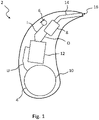
- FIG. 1 1 shows a hearing device 2 as an example of a device according to the invention for processing an audio signal, ie a hearing instrument set up to support the hearing ability of a hearing-impaired user.
- the hearing device 2 is a BTE hearing device that can be worn behind the ear of a user.
- the hearing aid 2 includes at least one microphone 6 as an input transducer and a receiver 8 as an output transducer within a housing 4 .
- the hearing aid 2 further comprises a battery 10 and a (particularly digital) signal processor 12.
- the signal processor 12 preferably comprises both a programmable sub-unit (for example a microprocessor) and a non-programmable sub-unit (for example an ASIC).
- the signal processor 12 is supplied with an electrical supply voltage U from the battery 10 .
- the microphone 6 picks up airborne noise from the surroundings of the hearing aid 2.
- the microphone 6 converts the sound into an (input) audio signal I containing information about the recorded sound.
- the input audio signal I is fed to the signal processor 12 within the hearing device 2, which modifies this input audio signal I to support the hearing ability of the user.
- the signal processor 12 outputs an output audio signal O, which contains information about the processed and thus modified sound, to the listener 8 .
- the listener 8 converts the output sound signal O into a modified airborne sound.
- This modified airborne sound is transmitted via a sound channel 14, which connects the receiver 8 to a tip 16 of the housing 4, and via a flexible sound tube (not explicitly shown), which connects the tip 16 to an earpiece inserted into the user's auditory canal transmitted to the user's ear canal.
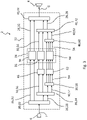
- the functional structure of the signal processor 12 is in 2 shown in more detail.
- the input audio signal I picked up by the microphone 6 is first digitized by an analog/digital converter integrated in the signal processor 12 or upstream of the signal processor 12 .
- the digitized input audio signal I is first fed to an analysis filter bank device 20 within the signal processor 12, which in 2 example shown comprises a first analysis filter bank 22 and a second analysis filter bank 24 connected downstream of this.
- the input audio signal I is divided in a first frequency split into a plurality of first frequency bands 26, ie first frequency channels, each carrying a subband signal of the input audio signal I.
- first frequency bands 26 In 2 are simply four first frequency bands 26 shown.
- the first analysis filter bank 22 divides the input audio signal I into 32 first frequency bands 26, for example.
- the frequency bands 26 have a uniform (first) bandwidth of 500 Hz, for example, and a uniform spectral spacing of 250 Hz.
- the second analysis filter bank 24 only acts on a (first) subgroup 28 of the frequency bands 26, which covers a range from 2 to 3 kHz at the low-frequency edge of the sound spectrum.
- the subgroup 28 includes a number of adjacent frequency bands 26, which includes the lowest (ie lowest frequency) first frequency band 26. in the in 2 example, the subgroup 28 includes the lower two of the four frequency bands 26; In practical implementation, the subgroup 28 includes, for example, the lower 12 of a total of 32 first frequency bands 26.
- the second analysis filter bank 24 splits each first frequency band 26 of the subgroup 28 into a number in a second frequency split (according to 2 split into two) second frequency bands 30, for example.
- the frequency bands 30 have a uniform (second) bandwidth of 125 Hz, for example, and a uniform spectral spacing of 62.5 Hz.
- the respective sub-band signals of the high-frequency frequency bands 26 of the subgroup 32 and of the frequency bands 30 are processed in a signal processing unit 34 (ie modified in terms of signaling).
- a signal processing unit 34 ie modified in terms of signaling
- the respective sub-band signal of each frequency band 26 of the subgroup 32 and of each frequency band 30 is amplified according to an individual (ie frequency-specific predetermined) amplification factor.
- the signal processing unit comprises 34 in the example according to 2 two sub-units 36 and 38 for the high-frequency frequency bands 26 of the sub-group 32 and for the frequency bands 30, the sub-units 36 and 38 each being designed specifically for the different bandwidth of the supplied frequency bands 26 and 30, respectively.
- the processed subband signals of the high-frequency frequency bands 26 of the subgroup 32 and the frequency bands 30 are combined to form the output audio signal O by a synthesis filter bank device 40 .
- the synthesis filter bank device 40 is mirror-symmetrical to the analysis filter bank device 20 . Accordingly, it comprises a second synthesis filter bank 42, which recombines the second frequency bands 30 to form the first frequency bands 26 of the subgroup 28, and a first synthesis filter bank 44, which combines the first frequency channels 26 of the first subgroup 28 and the subgroup 32 to the output -Audio signal O merges.
- the finer frequency splitting performed using analysis filter bank 24 causes a latency difference in the low-frequency subband signals of frequency bands 26 in subgroup 28 compared to the high-frequency subband signals of frequency bands 26 in subgroup 32, which in the absence of further measures leads to a distortion of the output audio signal O would lead.
- a predictor 46 is connected in the signal path of the frequency bands 30 in order to compensate for this latency difference (i.e. to completely eliminate it or at least to reduce it).
- the predictor 46 is preferably embodied as a non-linear predictor that continuously adapts during operation of the hearing aid 2, in particular as a Hammerstein model.
- the predictor 46 has specifically adapted parameters for each frequency band 30 supplied.
- the hearing aid 2 contains a plurality of predictors 46, 46′ connected in series, which in particular are applied to a plurality of the 2 specified positions are arranged and each compensate a part of the latency difference described above.
- the output audio signal O output by the first synthesis filter bank 44 is converted back into an analog signal by a digital-to-analog converter (not shown) which is integrated into the signal processor 12 or is connected downstream of the signal processor 12 and for output to the user of the hearing aid 2 to the handset 8 .
- a digital-to-analog converter (not shown) which is integrated into the signal processor 12 or is connected downstream of the signal processor 12 and for output to the user of the hearing aid 2 to the handset 8 .
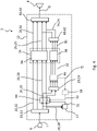
- the analysis filter bank device 20 and the synthesis filter bank device 40 are each constructed in three stages.
- the analysis filter bank device 20 in this embodiment includes a third analysis filter bank 50 which acts on a (first) subgroup 52 of the frequency bands 30 .
- the subgroup 52 again covers a low-frequency part of the part of the sound spectrum spanned by the frequency bands 30 as a whole.
- the subgroup includes 52, in particular - in the example according to 3 -
- every second frequency band 30 of the subgroup 52 is divided even more finely into several (according to 3 split into two) third frequency bands 54 (third frequency splitting).
- the frequency bands 54 have a uniform (third) bandwidth of 62.5 Hz, for example, and a uniform spectral spacing of 31.25 Hz.
- the sub-unit 38 of the signal processing unit 34 processes only the respective sub-band signals of the high-frequency frequency bands 30 of the second sub-group 56 3 additionally a further sub-unit 58, which is designed for the bandwidth of the frequency bands 54.
- the synthesis filter bank device 40 is also in the embodiment according to FIG 3 set up mirror-symmetrical to the analysis filter bank device 20 . It therefore includes, in addition to the first synthesis filter bank 44 and the second synthesis filter bank 42, a third synthesis filter bank 60 which, after signal processing, recombines the third frequency bands 54 to form the second frequency bands 30 of the subgroup 52.
- predictor 46 also acts only on the respective subband signals of high-frequency second frequency bands 30 of second subgroup 56.
- hearing aid 2 includes 3 a further predictor 62.
- the predictor 62 is preferably of the same type as the predictor 46, but designed in such a way that it compensates for the latency difference to the subband signals of the high-frequency first frequency bands 26 of the subgroup 32 caused by the second and third frequency splitting.
- the predictor 62 can also be arranged at different positions between the second analysis filter bank 24 and the second synthesis filter bank 42 . Furthermore, in variants of the embodiment according to 3 several predictors 62 can be connected in series, each compensating for part of the latency difference. In a further embodiment variant, the predictors 46 and 62 are connected in series. In this case, the predictor 46 is arranged between the first analysis filter bank 22 and the second analysis filter bank 24 or between the second synthesis filter bank 42 and the first synthesis filter bank 44 . In these cases, the predictor 62 is designed such that it only compensates for the latency difference caused by the third frequency splitting.
- FIG 4 shows a further embodiment of the hearing aid 2, which essentially corresponds to the embodiment 2 is equivalent to.
- the second frequency splitting of the low-frequency first frequency bands 26 of the subgroup 28 takes place here, however, only if the input audio signal I contains voiced speech (ie voiced spoken or sung sounds).
- a speech recognition module 64 is implemented in the signal processor 12 .
- the speech recognition module 64 recognizes the presence of voiced speech by analyzing the input audio signal I broken down into the first frequency bands 26, and particularly the low-frequency component thereof.
- the frequency bands 26 of the subgroup 28 are fed to the speech recognition module 64 as an input variable.
- the speech recognition module 64 recognizes the presence of voiced speech in particular from the presence of a pronounced fundamental frequency and/or the occurrence of the dominant frequencies (formants) that are characteristic of voiced sounds.
- the speech recognition module 64 Upon detection of voiced speech in the input audio signal I, the speech recognition module 64 outputs a control signal S1.
- a signal splitter 66 is connected in the signal path of the frequency bands 26 of the subgroup 28, which, depending on the control signal S1, transfers the subband signals of the frequency bands 26 of the subgroup 28 either to the second analysis filter bank 24 or the sub-unit 36 of the data processing unit 34 forwards.
- the control signal S1 is present (and thus when voiced speech is recognized in the input audio signal I)
- the signal splitter 66 forwards the subband signals of the frequency bands 26 of the subgroup 28 to the second analysis filter bank 24 .
- the function of the hearing aid corresponds to 2 4 the in 2 embodiment shown.
- the signal splitter 66 directs the subband signals of the frequency bands 26 of the subgroup 28 directly to the subunit 36 of the data processing unit 34 In this case, the subband signals of all first frequency bands 26 are processed without further frequency splitting, in particular amplified in a frequency-specific manner.
- the second frequency splitting is not activated depending on the recognition of voiced speech, but depending on the accuracy (reliability) of the prediction.
- the parameter Q is calculated, for example, from the mean value, the minimum value or the maximum value of the individual band-specific predictor gains.
- the predictor gain of a subband signal selected as a reference is used as the parameter Q.
- the parameter Q has a value that is all the higher, the more precisely the predictor 46 can predict the course of the supplied subband signals.
- evaluation module 68 will compare the parameter Q with a predetermined threshold value. As long as the parameter Q exceeds the threshold value, the evaluation module 68 outputs a control signal S2, which is fed to the signal splitter 66 instead of the control signal S1.
- the signal splitter 66 forwards the subband signals of the frequency bands 26 of the subgroup 28 to the second analysis filter bank 24 .
- the function of the hearing aid corresponds to 2 4 again the in 2 embodiment shown.
- the signal splitter 66 forwards the subband signals of the frequency bands 26 of the subgroup 28 directly to the subunit 36 of the data processing unit 34 for a predetermined period of time.
- the subband signals of all first frequency bands 26 are again processed without further frequency splitting, in particular amplified in a frequency-specific manner. No prediction then takes place. After the specified period of time, the second Frequency splitting and thus the prediction reactivated to check the accuracy of the prediction using the evaluation module 68 again.
- the speech recognition module 64 is not provided in the embodiment variant described above. Accordingly, the signal splitter 66 is controlled exclusively via the control signal S2.
- Both the speech recognition module 64 and the evaluation module 68 are provided.
- the signal splitter 66 is controlled here both by the control signal S1 and by the control signal S2.
- the control signals S1 and S2 are preferably AND-linked, so that the second frequency splitting is only activated by the signal splitter 66 when both the control signal S1 and the control signal S2 are present, i.e. when both the presence of voiced speech in the input Audio signal I was recognized and the prediction has sufficient accuracy.
- the parameter Q is calculated separately for each frequency band 26 of the first subgroup 28, in particular by determining the respective band-specific predictor gain, and compared with a respective band-specific threshold value.
- the evaluation module 68 outputs the control signal S2 band-specifically only for the frequency band 26 or the frequency bands 26 for which the band-specific predictor gain exceeds the respectively assigned threshold value.
- the signal splitter 66 activates the second frequency splitting selectively only for the frequency band 26 or frequency bands 26 concerned.
- control signal S1 is band-specifically generated when the voice recognition module 64 detects the presence of voiced speech in the respective frequency band 26. Accordingly, the signal splitter 66 is also activated in In this case, the second frequency split selectively only for the affected frequency band 26 or the affected frequency bands 26.
- the predictor 46 is only switched from the signal path connecting the microphone 6 to the earphone 8, but continues to run in the background of the signal processing (without the prediction having an effect on the output audio signal O) .
- This is achieved, for example, in that the signal splitter 66 is mirror-symmetrical to the representation according to FIG 4 between the second synthesis filter bank 42 and the first synthesis filter bank 44 is switched.
- the predictor 46 continuously outputs the characteristic Q even if the characteristic Q does not exceed the threshold value. That according to the embodiment 4 Described switching back of the signal switch 66 after the specified period of time to check the accuracy of the prediction again is not necessary here and therefore not provided.
Landscapes
- Engineering & Computer Science (AREA)
- Acoustics & Sound (AREA)
- Signal Processing (AREA)
- Health & Medical Sciences (AREA)
- Physics & Mathematics (AREA)
- Otolaryngology (AREA)
- Neurosurgery (AREA)
- General Health & Medical Sciences (AREA)
- Human Computer Interaction (AREA)
- Multimedia (AREA)
- Audiology, Speech & Language Pathology (AREA)
- Quality & Reliability (AREA)
- Computational Linguistics (AREA)
- Compression, Expansion, Code Conversion, And Decoders (AREA)
- Measurement Of The Respiration, Hearing Ability, Form, And Blood Characteristics Of Living Organisms (AREA)
Applications Claiming Priority (1)
| Application Number | Priority Date | Filing Date | Title |
|---|---|---|---|
| DE102021205251.7A DE102021205251B4 (de) | 2021-05-21 | 2021-05-21 | Verfahren und Vorrichtung zur frequenzselektiven Verarbeitung eines Audiosignals mit geringer Latenz |
Publications (1)
| Publication Number | Publication Date |
|---|---|
| EP4093052A1 true EP4093052A1 (fr) | 2022-11-23 |
Family
ID=81448592
Family Applications (1)
| Application Number | Title | Priority Date | Filing Date |
|---|---|---|---|
| EP22168308.9A Withdrawn EP4093052A1 (fr) | 2021-05-21 | 2022-04-14 | Procédé et dispositif de traitement sélectif en fréquence d'un signal audio à faible latence |
Country Status (4)
| Country | Link |
|---|---|
| US (1) | US11910162B2 (fr) |
| EP (1) | EP4093052A1 (fr) |
| CN (1) | CN115379366B (fr) |
| DE (1) | DE102021205251B4 (fr) |
Families Citing this family (2)
| Publication number | Priority date | Publication date | Assignee | Title |
|---|---|---|---|---|
| US12183029B2 (en) * | 2022-02-18 | 2024-12-31 | Htc Corporation | Device position correction method and device position correction system |
| DE102023200405A1 (de) * | 2023-01-19 | 2024-07-25 | Sivantos Pte. Ltd. | Binaurales Hörsystem mit zwei Hörinstrumenten sowie Verfahren zum Betrieb eines solchen Hörsystems |
Citations (4)
| Publication number | Priority date | Publication date | Assignee | Title |
|---|---|---|---|---|
| US20090290737A1 (en) * | 2008-05-21 | 2009-11-26 | Daniel Alfsmann | Method for optimizing a multilevel filter bank and corresponding filter bank and hearing apparatus |
| US20100094643A1 (en) * | 2006-05-25 | 2010-04-15 | Audience, Inc. | Systems and methods for reconstructing decomposed audio signals |
| EP3197181A1 (fr) | 2016-01-19 | 2017-07-26 | Sivantos Pte. Ltd. | Procédé de réduction du temps de latence d'un banc de filtrage destiné au filtrage d'un signal audio et procédé de fonctionnement sans latence d'un système auditif |
| CN111128174A (zh) * | 2019-12-31 | 2020-05-08 | 北京猎户星空科技有限公司 | 一种语音信息的处理方法、装置、设备及介质 |
Family Cites Families (12)
| Publication number | Priority date | Publication date | Assignee | Title |
|---|---|---|---|---|
| US4852175A (en) * | 1988-02-03 | 1989-07-25 | Siemens Hearing Instr Inc | Hearing aid signal-processing system |
| US5956674A (en) * | 1995-12-01 | 1999-09-21 | Digital Theater Systems, Inc. | Multi-channel predictive subband audio coder using psychoacoustic adaptive bit allocation in frequency, time and over the multiple channels |
| US6996198B2 (en) * | 2000-10-27 | 2006-02-07 | At&T Corp. | Nonuniform oversampled filter banks for audio signal processing |
| JP4286510B2 (ja) * | 2002-09-09 | 2009-07-01 | パナソニック株式会社 | 音響信号処理装置及びその方法 |
| DE102008024534A1 (de) * | 2008-05-21 | 2009-12-03 | Siemens Medical Instruments Pte. Ltd. | Hörvorrichtung mit einem Entzerrungsfilter im Filterbank-System |
| DE102008024490B4 (de) * | 2008-05-21 | 2011-09-22 | Siemens Medical Instruments Pte. Ltd. | Filterbanksystem für Hörgeräte |
| DE102010026884B4 (de) | 2010-07-12 | 2013-11-07 | Siemens Medical Instruments Pte. Ltd. | Verfahren zum Betreiben einer Hörvorrichtung mit zweistufiger Transformation |
| EP2560410B1 (fr) * | 2011-08-15 | 2019-06-19 | Oticon A/s | Contrôle de modulation de sortie dans un instrument auditif |
| EP2864983B1 (fr) * | 2012-06-20 | 2018-02-21 | Widex A/S | Procédé pour le traitement de son dans une prothèse auditive ainsi qu'une prothèse auditive |
| DE102014204557A1 (de) * | 2014-03-12 | 2015-09-17 | Siemens Medical Instruments Pte. Ltd. | Übertragung eines windreduzierten Signals mit verminderter Latenzzeit |
| DE102017203630B3 (de) * | 2017-03-06 | 2018-04-26 | Sivantos Pte. Ltd. | Verfahren zur Frequenzverzerrung eines Audiosignals und nach diesem Verfahren arbeitende Hörvorrichtung |
| DE102018206689A1 (de) * | 2018-04-30 | 2019-10-31 | Sivantos Pte. Ltd. | Verfahren zur Rauschunterdrückung in einem Audiosignal |
-
2021
- 2021-05-21 DE DE102021205251.7A patent/DE102021205251B4/de active Active
-
2022
- 2022-04-14 EP EP22168308.9A patent/EP4093052A1/fr not_active Withdrawn
- 2022-05-17 CN CN202210538122.0A patent/CN115379366B/zh active Active
- 2022-05-19 US US17/748,550 patent/US11910162B2/en active Active
Patent Citations (5)
| Publication number | Priority date | Publication date | Assignee | Title |
|---|---|---|---|---|
| US20100094643A1 (en) * | 2006-05-25 | 2010-04-15 | Audience, Inc. | Systems and methods for reconstructing decomposed audio signals |
| US20090290737A1 (en) * | 2008-05-21 | 2009-11-26 | Daniel Alfsmann | Method for optimizing a multilevel filter bank and corresponding filter bank and hearing apparatus |
| EP2124335B1 (fr) | 2008-05-21 | 2018-03-28 | Sivantos Pte. Ltd. | Procédé d'optimisation d'un banc de filtres multi-étage ainsi que banc de filtres correspondant et dispositif auditif |
| EP3197181A1 (fr) | 2016-01-19 | 2017-07-26 | Sivantos Pte. Ltd. | Procédé de réduction du temps de latence d'un banc de filtrage destiné au filtrage d'un signal audio et procédé de fonctionnement sans latence d'un système auditif |
| CN111128174A (zh) * | 2019-12-31 | 2020-05-08 | 北京猎户星空科技有限公司 | 一种语音信息的处理方法、装置、设备及介质 |
Also Published As
| Publication number | Publication date |
|---|---|
| CN115379366B (zh) | 2026-03-06 |
| CN115379366A (zh) | 2022-11-22 |
| DE102021205251A1 (de) | 2022-11-24 |
| DE102021205251B4 (de) | 2024-08-08 |
| US20220386042A1 (en) | 2022-12-01 |
| US11910162B2 (en) | 2024-02-20 |
Similar Documents
| Publication | Publication Date | Title |
|---|---|---|
| DE10228632B3 (de) | Richtungshören bei binauraler Hörgeräteversorgung | |
| DE69531828T2 (de) | Hörhilfegerät mit signalverarbeitungstechniken | |
| DE69933141T2 (de) | Tonprozessor zur adaptiven dynamikbereichsverbesserung | |
| EP1919257B1 (fr) | Réduction du bruit dépendant du niveau | |
| DE10331956C5 (de) | Hörhilfegerät sowie Verfahren zum Betrieb eines Hörhilfegerätes mit einem Mikrofonsystem, bei dem unterschiedliche Richtcharakteistiken einstellbar sind | |
| CH692884A5 (de) | Verfahren zur Verstärkung von Eingangssignalen eines Hörgerätes sowie Schaltung zur Durchführung des Verfahrens. | |
| EP2421282B1 (fr) | Appareil d'aide auditive et/ou de traitement d'acouphène | |
| EP1489884B1 (fr) | Procédé de commande d'une prothèse auditive et prothèse auditive avec système de microphone dans lequel différentes caractéristiques directionnelles sont réglables | |
| EP1489885A2 (fr) | Procédé pour l'opération d'une prothèse auditive aussi qu'une prothèse auditive avec un système de microphone dans lequel des diagrammes de rayonnement différents sont sélectionnables | |
| EP3454572A1 (fr) | Procédé de reconnaissance d'un défaut dans un appareil auditif | |
| EP4093052A1 (fr) | Procédé et dispositif de traitement sélectif en fréquence d'un signal audio à faible latence | |
| DE60016144T2 (de) | Hörhilfegerät | |
| EP3373599B1 (fr) | Procédé d'ajustement fréquentiel d'un signal audio et dispositif auditif fonctionnant selon ledit procédé | |
| EP1503612B1 (fr) | Prothèse auditive et méthode à l'opération d'une prothèse auditive avec un système de microphone dans lequel de différentes caractéristiques directionnelles sont sélectionnables | |
| DE10114101A1 (de) | Verfahren zum Verarbeiten eines Eingangssignals in einer Signalverarbeitungseinheit eines Hörgerätes sowie Schaltung zur Durchführung des Verfahrens | |
| EP1351550B1 (fr) | Procédé d'adaptation d'une amplification de signal dans une prothèse auditive et prothèse auditive | |
| EP4529225A1 (fr) | Système auditif et procédé de génération de béat monaural ou binaural | |
| EP2434781A1 (fr) | Procédé de reconstruction d'un signal vocal et dispositif auditif | |
| DE3027953A1 (de) | Elektro-akustisches hoergeraet mit adaptiver filterschaltung | |
| AT507844B1 (de) | Methode zur trennung von signalpfaden und anwendung auf die verbesserung von sprache mit elektro-larynx | |
| DE102020201615B3 (de) | Hörsystem mit mindestens einem im oder am Ohr des Nutzers getragenen Hörinstrument sowie Verfahren zum Betrieb eines solchen Hörsystems | |
| DE10114015A1 (de) | Verfahren zum Betrieb eines Hörhilfe- und/oder Gehörschutzgerätes sowie Hörhilfe- und/oder Gehörschutzgerät | |
| EP3913618A1 (fr) | Procédé de fonctionnement d'un appareil auditif et appareil auditif | |
| EP0723381B2 (fr) | Dispositif d'assistance auditive | |
| DE102023208468A1 (de) | Verfahren zur direktionalen Signalverarbeitung für ein Hörsystem |
Legal Events
| Date | Code | Title | Description |
|---|---|---|---|
| PUAI | Public reference made under article 153(3) epc to a published international application that has entered the european phase |
Free format text: ORIGINAL CODE: 0009012 |
|
| STAA | Information on the status of an ep patent application or granted ep patent |
Free format text: STATUS: THE APPLICATION HAS BEEN PUBLISHED |
|
| AK | Designated contracting states |
Kind code of ref document: A1 Designated state(s): AL AT BE BG CH CY CZ DE DK EE ES FI FR GB GR HR HU IE IS IT LI LT LU LV MC MK MT NL NO PL PT RO RS SE SI SK SM TR |
|
| STAA | Information on the status of an ep patent application or granted ep patent |
Free format text: STATUS: REQUEST FOR EXAMINATION WAS MADE |
|
| 17P | Request for examination filed |
Effective date: 20230522 |
|
| RBV | Designated contracting states (corrected) |
Designated state(s): AL AT BE BG CH CY CZ DE DK EE ES FI FR GB GR HR HU IE IS IT LI LT LU LV MC MK MT NL NO PL PT RO RS SE SI SK SM TR |
|
| STAA | Information on the status of an ep patent application or granted ep patent |
Free format text: STATUS: EXAMINATION IS IN PROGRESS |
|
| 17Q | First examination report despatched |
Effective date: 20240607 |
|
| STAA | Information on the status of an ep patent application or granted ep patent |
Free format text: STATUS: THE APPLICATION HAS BEEN WITHDRAWN |
|
| 18W | Application withdrawn |
Effective date: 20251128 |