EP4093237B1 - Gepäckartiger lederwarenartikel - Google Patents
Gepäckartiger lederwarenartikel Download PDFInfo
- Publication number
- EP4093237B1 EP4093237B1 EP21705247.1A EP21705247A EP4093237B1 EP 4093237 B1 EP4093237 B1 EP 4093237B1 EP 21705247 A EP21705247 A EP 21705247A EP 4093237 B1 EP4093237 B1 EP 4093237B1
- Authority
- EP
- European Patent Office
- Prior art keywords
- handle
- locking
- grip portion
- article according
- handle axle
- Prior art date
- Legal status (The legal status is an assumption and is not a legal conclusion. Google has not performed a legal analysis and makes no representation as to the accuracy of the status listed.)
- Active
Links
Images



Classifications
-
- A—HUMAN NECESSITIES
- A45—HAND OR TRAVELLING ARTICLES
- A45C—PURSES; LUGGAGE; HAND CARRIED BAGS
- A45C13/00—Details; Accessories
- A45C13/26—Special adaptations of handles
- A45C13/262—Special adaptations of handles for wheeled luggage
-
- A—HUMAN NECESSITIES
- A45—HAND OR TRAVELLING ARTICLES
- A45C—PURSES; LUGGAGE; HAND CARRIED BAGS
- A45C5/00—Rigid or semi-rigid luggage
- A45C5/03—Suitcases
-
- A—HUMAN NECESSITIES
- A45—HAND OR TRAVELLING ARTICLES
- A45C—PURSES; LUGGAGE; HAND CARRIED BAGS
- A45C13/00—Details; Accessories
- A45C13/26—Special adaptations of handles
-
- A—HUMAN NECESSITIES
- A45—HAND OR TRAVELLING ARTICLES
- A45C—PURSES; LUGGAGE; HAND CARRIED BAGS
- A45C5/00—Rigid or semi-rigid luggage
- A45C5/03—Suitcases
- A45C2005/037—Suitcases with a hard shell, i.e. rigid shell as volume creating element
-
- A—HUMAN NECESSITIES
- A45—HAND OR TRAVELLING ARTICLES
- A45C—PURSES; LUGGAGE; HAND CARRIED BAGS
- A45C13/00—Details; Accessories
- A45C13/26—Special adaptations of handles
- A45C13/262—Special adaptations of handles for wheeled luggage
- A45C2013/267—Special adaptations of handles for wheeled luggage the handle being slidable, extractable and lockable in one or more positions
Definitions
- the invention relates to an article of leather goods of the luggage type, comprising at least two half-shells secured to one another at least partially by a closing mechanism, as well as a deployable and retractable handle mechanism and which is at less partially housed in one of the half-shells. It may be, for example, a suitcase, or a trunk, or any other item of the same kind.
- Luggage comprising two half-shells and a closing mechanism, for example formed of a zipper, configured to connect the two half-shells in a closed configuration of the luggage; as well as a deployable and retractable handle mechanism which is at least partially housed in one of the half-shells.
- a closing mechanism for example formed of a zipper, configured to connect the two half-shells in a closed configuration of the luggage; as well as a deployable and retractable handle mechanism which is at least partially housed in one of the half-shells.
- the invention aims to provide an article of leather goods of the luggage type, of a similar type and having an improved deployable and retractable handle mechanism making it particularly safe to use, while remaining simple and convenient.
- the subject of the invention is therefore an article of leather goods of the luggage type, comprising at least two half-shells as well as a deployable and retractable handle mechanism which is at least partially housed in one of the half-shells and which is configured to lock /unlock a handle of the article in a position selected from a plurality of deployment positions of the handle relative to the half-shells, by rotation of a gripping portion of the handle;
- the deployable and retractable handle mechanism having a handle shaft to which is secured the gripping portion movable in rotation, at least one sheath mounted fixedly in one of the half-shells, at least one profile mounted movable in translation relative to the sheath, at least one locking/unlocking system secured to said at least one profile and housed at least partially in said at least one sheath, and at least one interface system configured to be actuated by the handle shaft and to actuate the locking/unlocking system, characterized in that said at least one system interface which comprises a cam bearing of generally cylindrical shape, secured by a
- the rotation of the gripping portion of the handle from one to the other of the first and second positions of the handle and of the handle shaft allows the locking/unlocking of the translation of the handle in relation to the half-shells, in order to deploy/retract the handle. In other words, it is possible to adjust the height of the luggage handle.
- the transmission of movement from the gripping portion of the handle and therefore from the handle shaft to the locking/unlocking system is carried out by the contact face of the transmission end of the cam bearing, which is secured on the handle shaft.
- Such an interface can be manufactured with great precision so as to generate a particularly reduced clearance between the rotation of the gripping portion of the handle and the locking/unlocking of the translation of the handle relative to the half-shells.
- the deployable and retractable handle mechanism can be configured so that the first position of the gripping portion and the handle shaft, called the locking position, is a stable position, while the second position of the gripping portion and the handle shaft, called the unlocking position, is an unstable position, the deployable and retractable handle mechanism being further configured to naturally return the gripping portion and the handle shaft to the first position.
- the deployable and retractable handle mechanism can be configured so that the second position of the gripping portion and the handle shaft, called the unlocking position, is a stable position, while the first position of the grip portion gripping and the handle shaft, called the locking position, i.e. an unstable position, the deployable and retractable handle mechanism being further configured to naturally return the gripping portion and the handle shaft to the second position.
- each of the first and second positions may be a stable position.
- Said cam bearing can be attached to the handle shaft.
- Said cam bearing can be secured to the handle shaft via at least one fixing member, for example a pin, passing through the handle shaft and of which at least one free end is housed in at least a window provided in the cam bearing.
- fixing member for example a pin
- Said at least one free end of said at least one fixing member can be configured to form a rotational stop of the handle shaft and therefore of the gripping portion.
- Said at least one interface system may comprise at least one pusher having a complementary contact face configured to cooperate directly with the contact face of the transmission end of said cam bearing.
- Said contact face of the transmission end of said cam bearing may have at least one generally ramp profile directed towards a projecting end, while said complementary contact face of said at least one pusher may have a generally flat profile with a protuberance protruding.
- Said at least one interface system is configured so that, in the first position of the gripping portion and the handle shaft, the projecting end of the generally ramped profile is substantially in contact with the projecting protuberance, while that in the second position of the gripping portion and the handle shaft, it is the generally ramp profile of said contact face of the transmission end of said cam bearing which comes substantially into contact with the projecting protuberance of said complementary contact face of said at least one pusher.
- the locking/unlocking system may comprise at least one movable tube inside said at least one profile and configured to be actuated by said at least one pusher.
- Said locking/unlocking system may comprise at least one seal which, in a first position of the gripping portion and the handle shaft, is compressed and applied tight against an internal face of said at least one sheath to keep said fixed at the less one profile relative to said at least one sheath, thus locking the handle in the selected position and which, in a second position of the gripping portion and the handle shaft obtained by rotation of the gripping portion, is decompressed and allows free sliding of said at least one profile in said at least one sheath, thus unlocking the handle.
- the locking/unlocking system may comprise at least one sleeve secured to said at least one profile, and at least one clamp secured to said at least one tube, with said at least one joint which is secured to both said at least one sleeve and audit at least one clamp.
- the locking/unlocking system can be configured so that the actuation of said at least one pusher by the transmission end of said cam bearing causes the movement of said at least tube in the profile and in at the same time said at least one clamp relative to said at least one sleeve; and that the movement of said at least one clamp causes the compression or decompression of said at least one joint following its direction of movement.
- Said at least one interface system may comprise at least one elastic member, in particular for returning the gripping portion of the handle at least from one of its second and first positions towards the other of its first and second positions, for example a torsion spring, mounted on the handle shaft.
- at least one elastic member in particular for returning the gripping portion of the handle at least from one of its second and first positions towards the other of its first and second positions, for example a torsion spring, mounted on the handle shaft.
- Said at least one interface system may comprise a spring bearing to which is secured, via a first end, said at least one elastic member and in which the handle shaft is movably mounted, with said at least one elastic member which is interposed between said spring bearing and said cam bearing and which is secured by a second end, opposite its first end, on a side of said cam bearing which is opposite the side of the latter where the transmission end is located.
- the deployable and retractable handle mechanism may have a general U shape, with the gripping portion of the handle and the handle shaft which form a bottom of the U and each branch of the U which is formed at least by one said sheath, a so-called profile and a so-called locking/unlocking system.
- the deployable and retractable handle mechanism may have a general L shape, with the gripping portion of the handle and the handle shaft which form a branch of the L and the sheath, the profile and the locking system/ unlocking which form another branch of the L.
- the half-shells can be secured together at least partially by a closing mechanism.
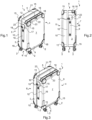
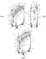
- THE figures 1 to 6 illustrate an article of leather goods, of the luggage type, and in particular here a suitcase 1 with wheels 2, shown in closed configuration and from different viewing angles.
- the suitcase 1 has a generally parallelepiped shape, having six sides, including a front wall 3, a rear wall 4, upper and lower side walls 5 and 6, a bottom wall 7 and a top wall 8.
- the upper side wall 5 and the lower side wall 6 are opposite and each extend at one end from the rear wall 4 and at an opposite end from the front wall 3, which is opposite the rear wall 4.
- the bottom walls and from above 7 and 8 are opposite and are each connected to the front 3, rear 4 and upper and lower side walls 5 and 6.
- the suitcase 1 is formed of a substantially rigid envelope having two half-shells called lower shell 9 and upper shell 10.
- the lower and upper half-shells 9 and 10 define an internal space in the closed configuration of the suitcase 1.
- the lower and upper half-shells 9 and 10 can be covered with an ornamental covering, for example in leather.
- the wheels 2 of the suitcase 1 protrude from its lower side wall 6.
- the suitcase 1 is provided at the corners of the lower and upper half-shells 9 and 10 with reinforcing members 15.
- the suitcase 1 has a fixed handle 16 secured to its front wall 3, substantially in the middle of the thickness of the suitcase 1.
- the suitcase 1 generally has a height defined substantially by the distance separating the side walls 5 and 6; a width defined substantially by the distance separating the front and rear walls 3 and 4; and a thickness defined substantially by the distance separating the bottom and top walls 7 and 8.
- the suitcase 1 has a connecting strip (not visible) provided on its rear wall 4.
- the connecting strip 11 forms a permanent junction between the lower and upper half-shells 9 and 10.
- the connecting strip 11 further forms a hinge for the passage of the suitcase 1 from its closed configuration to an open configuration (not shown) in which the lower and upper half-shells 9 and 10 are spaced apart from each other.
- the suitcase 1 is provided with a zipper 12 which extends on either side of the connecting strip 11, along the perimeter of the luggage.
- the perimeter of the suitcase 1 is formed by the front wall 3 or fourth side, the rear wall 4 or first side, and the side walls 5 and 6 or second and third sides.
- the zipper 12 is configured to connect the lower and upper half-shells 9 and 10 in the closed configuration of the suitcase 1.
- the zipper here has two pull tabs 19 intended to be moved in the direction of the connecting strip, via the front wall 3 then the respective side walls 5 and 6.
- the suitcase 1 is provided with a lock 17 at least partially integrated into the envelope of the suitcase 1 and to which the two zippers 19 can be mechanically and securely attached in the closed configuration of the suitcase 1, i.e. that is to say when the zipper 12 is closed.
- the suitcase 1 further comprises a deployable and retractable handle 18 (hereinafter handle) and a deployable and retractable handle mechanism 20 (hereinafter called handle mechanism) which are here at least partially housed in the lower half-shell 9 .
- handle a deployable and retractable handle 18
- handle mechanism a deployable and retractable handle mechanism 20
- the handle mechanism 20 is configured to lock or unlock the handle 18 of the suitcase 1 in a position selected from a plurality of deployment positions of the handle 18 relative to the lower and upper half-shells 9 and 10.
- the handle mechanism 20 here has a general U shape, with the bottom of the U which is introduced into a housing 23 provided in the upper side wall 5 of the suitcase 1, when the handle 18 is retracted, and the branches of the U which extend at least partially along the front and rear walls 3 and 4 and towards the lower side wall 6.
- the suitcase 1 further comprises an ejection button 22 operable from outside the suitcase 1 and housed in the upper side wall 5.
- the handle 18 is automatically and partially ejected from a predetermined height.
- FIG 1 shows the ejection button 22 not actuated, or not pushed
- the Figure 3 shows the ejection button 22 activated, or pushed and therefore pressed into the upper side wall 5
- the figure 4 shows the eject button 22 released.
- the handle 18 has been ejected.
- the gripping portion 21 is located here substantially in the center of the bottom of the U formed by the handle mechanism 20.
- the handle mechanism 20 is not operated and the handle 18 is retracted.
- the handle mechanism 20 is operated via the eject button 22 to eject the handle 18.
- the handle mechanism 20 is actuated via the gripping portion 21 with a view to deploying the handle 18 in a selected position and locking it in this position.
- the handle mechanism 20 locks the handle 18 in the selected position and, in a second position of the gripping portion 21 obtained by rotation of the gripping portion 21, the handle mechanism 20 unlocks the handle 18 which can then be deployed or retracted.
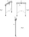
- THE figures 7 to 9 show the handle mechanism 20 which has a general U shape. This is essentially the part of the handle mechanism 20 which extends at least partially from the lower half-shell.
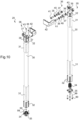
- THE figures 10 to 16 show the handle mechanism 20, in different states, including partially assembled, partially disassembled and enlarged for certain parts.
- FIG. 10 shows a part of the handle mechanism 20 configured to be fully housed in the front and rear walls 3 and 4.
- the handle mechanism 20 here comprises two sheaths 30 fixedly mounted respectively in the front and rear walls 3 and 4.
- Each sheath 30 is hollow and has a tubular shape.
- Each sheath 30 has on an external face fixing wells 32 and securing zones 31, for example by gluing, to ensure the retention of the sheaths 30 respectively in the front and rear walls 3 and 4.
- the handle mechanism 20 comprises, at the bottom of each sheath 30, an elastic ejection member 34, formed for example here by a compression spring, intended to eject the handle 18 when the ejection button 22 is actuated.
- Each elastic ejection member 34 is partially housed in an end piece 35 secured to the bottom of the respective sheath 30, here for example by means of fixing screws 99 inserted in respective fixing wells 32.
- Each sheath 30 here has an enlarged internal section in which the elastic ejection member 34 of the handle 18 can extend (see below).
- the handle mechanism 20 comprises, at the top of each sheath 30, a guide system 36 formed of a plurality of rollers 37 and bearings 38 secured on an ear 39 formed projecting at a high end of the sheath 30.
- Spacers 40 are here housed in the rollers 37, between the bearings 38, and each assembly formed by a roller 37, a spacer 40 and two bearings 38 is secured here on an ear 39 for example via fixing screws 41.
- the handle mechanism 20 here comprises a casing 42 secured to the upper end of each sheath 30.
- Each casing 42 has a substantially corner shape, with a branch of the corner which is located opposite the respective ear 39, and therefore opposite the rollers 37 and bearings 38, and which is secured here on a respective sheath 30 for example via fixing screws 43 inserted into the respective fixing wells 32; and with the other branch of the corner which extends behind an assembly formed by a roller 37, a spacer 40 and two bearings 38.
- the arrangement of the casings 42 vis-à-vis the ears 39 of the sleeves 30 makes it possible to substantially form protection at least for the guiding system 36.
- Each casing 42 is provided with a re-entrant edge 44, directed towards the respective sheath 30 and slightly closing the upper end of the sheath 30 which is open.
- each casing 42 forms an end stop for the deployment of the handle 18 (see below) with respect to the respective sheath 30.
- FIG. 11 shows a part of the handle mechanism 20 configured to be partially housed in the front and rear walls 3 and 4 and to slide relative to the sheaths 30 and thus be at least partially projecting from the lower half-shell 9; while the figures 12 to 15 illustrate in detail certain elements of this part of the mechanism.
- the handle mechanism 20 comprises a handle shaft 45 to which the gripping portion 21 movable in rotation is secured.
- the handle shaft 45 projects from either side of the gripping portion 21 of the handle 18.
- the handle mechanism 20 here comprises two profiles 46 configured to be mounted movable in translation relative to the sheaths 30.
- pebbles visible on the Figure 7 are configured to be in contact with the side faces of a respective profile 46.
- the handle mechanism 20 comprises a locking/unlocking system 47 secured to each of the profiles 46, housed at least partially at the bottom of a respective sheath 30, and configured to be actuated by the handle shaft 45.
- the handle mechanism 20 is configured so that the first position of the gripping portion 21 and thus of the handle shaft 45, or locking position, is a stable position, while the second position of the gripping portion 21 and therefore of the handle shaft 45, or unlocking position, i.e. an unstable position, the handle mechanism 20 being further configured to naturally recall the gripping portion 21 and also the shaft handle 45 in the first position.
- the handle mechanism 20 here has a general U shape.
- the gripping portion 21 of the handle 18 and the handle shaft 45 form the bottom of the U and each branch of the U is formed by a sheath 30, a profile 46 and a locking/unlocking system 47.
- the locking/unlocking system 47 comprises a movable tube 48 inside each profile 46 and configured to be actuated by the handle shaft 45, a sleeve 49 secured to each profile 46, and a clamp 50 secured to the pipe 48.
- the locking/unlocking system 47 includes seals 51.
- the locking/unlocking system 47 is configured to, in the first position of the gripping portion 21 and the handle shaft 45, compress each joint 51 so as to apply them tight against the internal faces of the respective sheaths 30 to maintain fixes the respective profiles 46 relative to the sheaths 30, thus locking the handle 18 in the selected position.
- the locking/unlocking system 47 is configured to, in the second position of the gripping portion 21 and the handle shaft 45 obtained by rotation of the gripping portion 21, decompress each joint 51 so as to allow free sliding respective profiles 46 in the respective sheaths 30, thus unlocking the handle 18.
- Each joint 51 is secured to both a respective sleeve 49 and a respective clamp 50.
- the locking/unlocking system 47 is configured so that the actuation of the handle shaft 45 causes the movement of each tube 48 in a respective profile 46 and at the same time of each clamp 50 relative to the respective sleeve 49 .
- the movement of the clamp 50 causes the compression or decompression of a respective joint 51 depending on its direction of movement.
- each clamp 50 can slide in the enlarged section of a respective sheath 30, even if the joint 51 is compressed.
- each joint 51 comprises a body 52 and each clamp 50 comprises a base 53 around which the body 52 of the joint 51 is mounted.
- Each joint 51 further comprises one or more fixing lugs 54 projecting from the body 52 and each sleeve 49 is provided with one or more notches 55 in which the fixing lug(s) 54 are secured.
- Each clamp 50 further comprises a rod 56 which extends projecting from the base 53 and which has a thinned end 57 secured with one end of a respective tube 48.
- Each sleeve 49 is mounted around the rod 56 of a respective clamp 50 and each body 52 of joint 51 is sandwiched between a respective sleeve 49 and a respective clamp 50.
- Each sleeve 49 comprises extension walls 58 intended to be introduced into a respective profile 46.
- Each sleeve 49 is provided with one or more positioning studs 59 provided on one or more of the extension walls 58, thus forming latching members.
- Each positioning stud 59 is configured to be housed in a corresponding orifice 60 provided in a respective profile 46.
- Each sleeve 49 is provided here with gadroons 13 to facilitate the positioning of the sleeve 49 in the respective profile 46.
- the locking/unlocking system 47 comprises an elastic member 62 mounted around each rod 56 of a respective clamp 50, inside a respective sleeve 49, between a first stop formed on a respective tube 48 and a second stop, opposite the first stop, formed in a respective sleeve 49.
- the first stop is here formed by a washer 61 partially housed in a groove (not shown) provided on each tube 48.
- Each elastic member 62 is here for example formed by a spring having a natural tendency to bias the washer 61 and therefore the respective tube 48.
- each sleeve 49 is fixed relative to the profile 46, the elastic member 62 thus tends to return the respective tube 48 upwards and therefore to bring the base 53 closer to the respective clamp 50 so as to compress the body 52 of the respective joint 51.
- the handle mechanism 20 here comprises two interface systems 63 configured to be actuated by the handle shaft 45 and to actuate each locking/unlocking system 47, via a respective pusher 64 interposed between each locking/unlocking system 47 and each interface system 63.
- each pusher 64 has the shape of a substantially parallelepiped block and is configured to cover a high free end of a respective tube 48, to which it is secured by means of, for example, a fixing screw 65.
- Each pusher 64 is provided, on the side opposite the respective tube 48, with a so-called complementary contact face 68 which here has a generally flat profile with a projecting protuberance 69, formed substantially in the center of the complementary contact face 68.
- Each pusher 64 is partially inserted into a respective profile 46, by a high end which is opposite to that where the locking/unlocking system 47 is located.
- each profile 46 there is a trim 66 which protects access to the branches of the U formed by the handle mechanism 20.
- This hubcap 66 is further secured, here for example by means of screws 67, to the bottom of the U which this handle mechanism 20 forms, and in particular to a support part 70 which this handle mechanism 20 also includes (see below -After).
- Each interface system 63 comprises a cam bearing 71, a spring bearing 73, as well as an elastic return and/or positioning member 74 and 75 interposed between the cam bearing 71 and the spring bearing 73.
- the elastic member is formed by both a return and positioning spring 74.
- a return and positioning spring 74 is configured on the one hand, to return the handle shaft 45 and the gripping portion 21 from its second position towards its first position and on the other hand, to stress the spring bearing 73 on the support part 70, or even to stress the cam bearing 71 vis-à-vis the respective pusher 64 and therefore of the respective profile 46.
- the elastic member is formed by a positioning spring 75 configured to stress the spring bearing 73 on the support part 70, or also to stress the cam bearing 71 with respect to the respective pusher 64 and therefore of the respective profile 46.
- Each cam bearing 71 has a generally cylindrical shape, secured by a first end to the handle shaft 45, and provided at a second end, opposite the first end, with a transmission end piece 76 having a contact face 79 which, in a first position of the gripping portion 21 and the handle shaft 45, is configured to control a locking/unlocking system 47, via the respective pusher 64, so as to lock the handle 18 in the selected position and which, in a second position of the gripping portion 21 and the handle shaft 45 obtained by rotation of the gripping portion 21, is configured to control the respective locking/unlocking system 47 so as to unlock the handle 18 .
- the contact face 79 of the transmission end 76 of each cam bearing 71 here has a generally ramp profile directed towards a projecting end 80.
- each cam bearing 71 The contact face 79 of the transmission end 76 of each cam bearing 71 is configured to cooperate directly with the complementary contact face 68 of a respective pusher 64.
- Each interface system 63 is configured so that, in the first position of the gripping portion 21 and the handle shaft 45, the projecting end 80 of the generally ramped profile of the contact face 79 of the bearing respective cam 71 is substantially in contact with the projecting protuberance 69 of the complementary contact face 68 of the respective pusher 64.
- Each interface system 63 is further configured so that, in the second position of the gripping portion 21 and the handle shaft 45, it is the generally ramp profile of the contact face 79 of the bearing. respective cam 71 which comes substantially into contact with the projecting protuberance 69 of the complementary contact face 68 of the respective pusher 64.
- each locking/unlocking system 47 is configured so that the actuation of the respective pusher 64 by the transmission end 76 of the respective cam bearing 71 causes the movement of the respective tube 48 in the respective profile 46, and at the same time time the movement of the respective clamp 50 relative to the respective sleeve 49, while the movement of the clamp 50 causes the compression or decompression of the respective joint 51 depending on its direction of movement.
- each cam bearing 71 is attached to the handle shaft 45.
- Each cam bearing 71 is secured to the handle shaft 45 via a fixing member 72.
- the free ends of the pins 72 are here configured to form rotational stops of the handle shaft 45 and therefore of the gripping portion 21 (see below).
- Each spring bearing 73 is movably mounted on the handle shaft 45 and is secured, by a first end, to the respective spring 74 or 75, itself mounted around the handle shaft 45.
- the springs 74 and 75 are further secured by a second end, opposite the respective first end, on a side of the respective cam bearing 71 which is opposite the side of the latter where the transmission end 76 is located.
- Each support part 70 (already introduced above) of the handle mechanism is configured to at least partially accommodate both a respective portion of the handle shaft 45, a respective interface system 63, including a cam bearing 71 , a spring bearing 73, one of the springs 74 or 75, as well as a respective pusher 64.
- Each support piece 70 extends generally longitudinally and has a base 82 substantially in the shape of a gutter, a wall 81 in the shape of arch and which projects from the base 82 to have a generally cylindrical shape, a complementary wall 83 also in the shape of an arch and which projects from the base 82 to have a generally cylindrical shape, as well as a complementary housing 84 provided transversely in base 82.
- the complementary wall 83 is provided on a first side of the support part 70 and forms an introduction orifice for the respective portion of the handle shaft 45.
- the complementary housing 84 is provided substantially vertically in the base 82, on a second side of the support part 70, opposite its first side.
- the additional housing 84 is designed to accommodate a portion of a profile 46 and the pusher 64 inserted into the latter.
- the wall 81 is provided substantially close to the additional housing 84.
- the wall 81 forms both a guide and a stop in rotation for the respective interface system 63 and for the handle shaft 45 between the first position of the gripping portion 21 and the handle shaft 45, where the system locking/unlocking 47 locks the handle 18 in the selected position, and the second position of the gripping portion 21 and the handle shaft 45 obtained by rotation of the gripping portion 21, where the locking/unlocking system 47 unlocks handle 18.
- the wall 81 forming both a guide and a stop in rotation is configured so that the cam bearing 71 is introduced through the latter, with the cam bearing 71 which is provided with a positioning collar 85, or shoulder, placed in contact with wall 81.
- the wall 81 is provided with a shoulder 94 against which the free ends of the pins 72 abut in the second position of the gripping portion 21 and the handle shaft 45.
- the complementary wall 83 forms both a guide and a stop in translation for the spring bearing 73 and is configured so that the spring bearing 73 is introduced through the latter, with the spring bearing 73 which has a positioning collar 86, or shoulder, placed in contact with the complementary wall 83.
- the spring 74 or 75 is for its part interposed between a complementary collar 87, or shoulder, provided on the cam bearing 71 and a complementary collar 88, or shoulder, provided on the spring bearing.
- the spring bearing 73 is provided with a fixing notch 90 configured to receive, if necessary, a fixing lug 92 of the return spring 74.
- the cam bearing 71 is provided with a similar fixing notch (not shown) configured to receive, if necessary, a fixing lug 92 opposite the return spring 74.
- the complementary wall 83 is further provided with a positioning notch 91 configured to receive a positioning pin 89, or key, provided on the spring bearing 73.
- Each spring bearing 73 further comprises lugs 33 provided projecting from the free end of the spring bearing 73 towards the complementary wall 83, which has complementary recesses (not illustrated) provided to accommodate these lugs 33.
- FIG. 16 shows in more detail the locking system 93 of the handle 18 which can be activated via the ejection button 22.
- the blocking system 93 is provided with two blocking fingers 95, or bolts, configured to form upper stops and prevent the sliding of the profiles 46.
- each profile 36 is provided with a notch 14 (see Figure 11 ) provided at its upper end to allow the passage of a respective blocking finger 95.
- the blocking system 93 comprises two actuating arms 96 from which the blocking fingers 95 project and which are configured to bring together or spread the locking fingers 95, or bolts, from the profiles 46, via a pivot movement generated around a pivot part 97.
- the pivot part 97 is moved by the actuation of the ejection button 22 which acts on an actuation tab 98 projecting from the pivot part 97.
- the ejection button 22 when the ejection button 22 is actuated, the latter acts on the actuating tab 98 which rotates the pivot part 97, which translates the actuating arms 96 to spread the locking fingers 95 until 'to be outside the notches 14 of the profiles 46 and thus allow them to slide.
- the profiles 46 and more generally the handle 18 are then automatically ejected by the elastic ejection members 34, from a predetermined height corresponding substantially to the enlarged section of the sheaths 30.
- the rotation of the gripping portion 21 of the handle 18 from one to the other of the first and second positions of the handle 18 and the handle shaft 45 allows the locking/ unlocking the translation of the handle 18 relative to the lower and upper half-shells 9 and 10, with a view to deploying/retracting the handle 18.
- the locking of the handle 18 in a selected position is here obtained by expansion of the seal 51 and therefore by friction between the seal 51 and the internal face of the sheath 30, thus generating mechanical resistance between the surfaces which are in tight contact.
- the mechanical resistance generated is sufficient to prevent the translation of the profile 46 in the sheath 30 when the user of the suitcase 1 causes the latter to move, whether for example when carrying it or when rolling it.
- the locking/unlocking system 47 with joint 51 is silent because the compression and decompression of the joint 51 occurs without noise.
- the locking/unlocking system 47 with seal 51 makes it possible to improve the guidance of the profile 46 in the sheath 30 because even in its decompressed state where the seal 51 allows the translation of the profile 46 relative to the sheath 30, the seal 51 can be found substantially in contact with the internal face of the sheath 30.
- this play compensation promotes the guidance of the profile 46 and makes the handle mechanism 20 more ergonomic.
- the transmission of movement from the gripping portion 21 of the handle 18 and therefore from the handle shaft 45 to the locking/unlocking system 47 is carried out by the face of contact of the transmission end 76 of the cam bearing 71, which is secured to the handle shaft 45.
- Such an interface can be manufactured with great precision so as to generate a particularly reduced clearance between the rotation of the gripping portion 21 of the handle 18 and the locking/unlocking of the translation of the handle 18 relative to the lower half-shells and higher 9 and 10.
- Such transmission of movement from the gripping portion 21 of the handle 18 and therefore from the handle shaft 45 to the locking/unlocking system 47 is also ensured precisely and safely by the support part 70 which allows both to house the locking/unlocking system 47 and a portion of the handle shaft 45, and also to guide them when they are rotated between the first locking position of the handle 18 and the second unlocking position of the handle 18, and vice versa.
- THE figures 17 to 32 show the different steps to move from the first locked position of the handle 18 where it is in a retracted configuration, to its second unlocked position to move it into an deployed configuration, then to return to its first locked position, but in its deployed configuration , that is to say at a height selected. These steps are carried out using the handle mechanism 20 described above with reference to the embodiment of the handle mechanism 20 illustrated in particular on the figures 7 to 16 .
- THE figures 17 to 20 are views similar to those of figures 7 to 9 , but showing the handle mechanism 20 in partial section, in the first locked position of the handle 18 where it is in the retracted configuration.
- the blocking system 93 is in a configuration where the blocking fingers 95 prevent the sliding of the profiles 46, with the latter which are totally or almost completely inserted into the sheaths (not shown in these figures), so that the The elastic ejection member 34 is compressed between the clamp 50 and the end piece 35.
- each cam bearing 71 The projecting end 80 of the contact face 79 of the transmission end 76 of each cam bearing 71 is substantially in contact with the projecting protuberance 69 of the contact face 68 of a respective pusher 64.
- the free ends of the pins 72 are at a distance from the shoulder 94 provided on the wall 81 of the cam bearing 71.
- the compressed 51 seals are found here in the part of the sleeves which has an enlarged internal section.
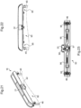
- THE figures 21 to 23 show the actuation of the ejection button 22, located adjacent to the gripping portion 21, with a view to controlling the blocking system 93 and thus ejecting the profiles 46 and therefore the handle 18 from a predetermined height.
- Pressing the ejection button 22 makes it possible to act on the actuating tab 98 which rotates the pivot part 97, which translates the actuating arms 96 to move the locking fingers 95 away from the profiles 46 and thus allow them to slide.
- the profiles 46 and more generally the handle 18 are then automatically ejected by the elastic ejection members 34, from a predetermined height corresponding substantially to the enlarged section of the sheaths 30.
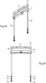
- THE figures 24 to 26 show the handle 18 ejected from a predetermined height which corresponds substantially to the height of the enlarged internal section provided in each sheath (not illustrated).
- the profiles 46 are partially projecting from the lower half-shell 9 (partially illustrated) even though the gripping portion 21 of the handle 18 has not been actuated.
- the cam insert 71 is in the same position as on the Figure 20 (it has not been rotated) and the tubes 48 are not stressed and the elastic members 62 hold the clamps 50 as close as possible to the sleeves 49 so that the joints 51 are compressed.
- each assembly formed of a profile 46, a tube 48 and also a sleeve 49, a clamp 50, an elastic member 62 and a seal 51 has been slid upwards by the force applied by each elastic ejection member 34, bearing on the respective end piece 35.
- each cam bearing 71 The projecting end 80 of the contact face 79 of the transmission end 76 of each cam bearing 71 is then at a distance from the projecting protuberance 69 of the contact face 68 of a respective pusher 64, while the generally ramp profile of the contact face 79 of this transmission end piece presses on the complementary contact face 68 of the pusher 64.
- the tubes 48 are moved and act against the elastic members 62 to separate the clamps 50 from the sleeves 49 and thus decompress the joints 51.
- the profiles 46 can then slide in the sheaths (not illustrated) without being hindered by the joints 51, which then only serve to guide the sliding, like the rollers 37.
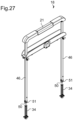
- the handle 18 can thus be brought into a selected deployment position.
- the profiles 46 and the clamps 50 are located at a distance from the elastic ejection member 34.
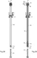
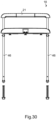
- THE figures 30 to 32 show the gripping portion 21 of the handle 18 returned to its first position.
- the gripping portion 21 is therefore no longer used.
- each cam bearing 71 The projecting end of the contact face of the transmission end of each cam bearing 71 is therefore substantially in contact with the projecting protuberance of the contact face of a respective pusher 64 (as on the Figure 20 ).
- the free ends of the pins 72 have returned to a distance from the shoulder 94 provided on the wall 81 of the respective cam bearing 71.
- the compressed seals 51 are found here in the part of the sleeves (not shown) which is not provided with an enlarged internal section so that the seals 51 maintain the profiles 46 in position in the respective sleeves.
- the deployable and retractable handle mechanism can be configured so that the second position of the gripping portion and the handle shaft, called the unlocking position, is a stable position, while the first position of the gripping portion and the handle shaft the handle shaft, called the locking position, is an unstable position, the deployable and retractable handle mechanism being further configured to naturally return the gripping portion and the handle shaft to the second position; or each of the first and second positions can be a stable position.
- the deployable and retractable handle mechanism may have a general L shape rather than a U shape, with the gripping portion of the handle and the handle shaft forming a branch of the L and the scabbard, the profile and the locking/unlocking system which forms another branch of the L.
- the gripping portion of the handle and the handle shaft may be projecting from the upper side wall rather than in a housing of the latter. In this case, it may be possible to operate the handle mechanism before the handle ejects, or there may even be no handle ejection system.
- the leather goods item may not have a secure lock.
- the leather goods item may have no zipper and simply have a clasp.
- the leather goods item is not a suitcase but a trunk, or any other item of the same kind.
Landscapes
- Purses, Travelling Bags, Baskets, Or Suitcases (AREA)
- Treatment And Processing Of Natural Fur Or Leather (AREA)
Claims (15)
- Lederartikel in der Art eines Gepäckstücks, welcher mindestens zwei Halbschalen (9, 10), sowie einen ausziehbaren und einziehbaren Griffmechanismus (20) beinhaltet, der mindestens teilweise in einer der Halbschalen untergebracht ist, und der konfiguriert ist, um einen Griff (18) des Artikels (1) in einer Position, die aus einer Vielzahl von Auszugspositionen des Griffes in Bezug auf die Halbschalen ausgewählt wird, durch Drehen eines Greifabschnitts (21) des Griffes zu verriegeln/entriegeln; wobei der ausziehbare und einziehbare Griffmechanismus eine Griffwelle (45), an der der drehbewegliche Greifabschnitt festgemacht ist, mindestens eine fest in einer der Halbschalen montierte Pinole (30), mindestens ein in Bezug auf die Pinole translationsbewegliches Profil (46), mindestens ein an dem mindestens einen Profil festgemachtes und mindestens teilweise in der mindestens einen Pinole untergebrachtes Verriegelungs-/Entriegelungssystem (47), und mindestens ein Schnittstellensystem (63) beinhaltet, das konfiguriert ist, um durch die Griffwelle betätigt zu werden, und um das Verriegelungs-/Entriegelungssystem zu betätigen, dadurch gekennzeichnet, dass das mindestens eine Schnittstellensystem ein Nockenlager (71) in einer allgemeinen zylindrischen Form beinhaltet, das durch ein erstes Ende an der Griffwelle festgemacht ist, und an einem zweiten Ende, entgegengesetzt zum ersten Ende, mit einem Übertragungsendstück (76) versehen ist, das eine Kontaktfläche (79) aufweist, die in einer ersten Position des Greifabschnitts und der Griffwelle konfiguriert ist, um das mindestens eine Verriegelungs-/Entriegelungssystem derart anzusteuern, um den Griff in der ausgewählten Position zu verriegeln, und die in einer zweiten Position des Greifabschnitts und der Griffwelle, die durch Drehen des Greifabschnitts erhalten wird, konfiguriert ist, um das mindestens eine Verriegelungs-/Entriegelungssystem derart anzusteuern, um den Griff zu entriegeln.
- Artikel nach Anspruch 1, dadurch gekennzeichnet, dass der ausziehbare und einziehbare Griffmechanismus (20) konfiguriert ist, damit die erste Position des Greifabschnitts (21) und der Griffwelle (45), Verriegelungsposition genannt, eine stabile Position ist, während die zweite Position des Greifabschnitts und der Griffwelle, Entriegelungsposition genannt, eine instabile Position ist, wobei der ausziehbare und einziehbare Griffmechanismus weiter konfiguriert ist, um den Greifabschnitt und die Griffwelle natürlich in die erste Position zurückzustellen.
- Artikel nach einem der Ansprüche 1 und 2, dadurch gekennzeichnet, dass das Nockenlager (71) an der Griffwelle (45) beigebracht ist.
- Artikel nach Anspruch 3, dadurch gekennzeichnet, dass das Nockenlager (71) durch mindestens ein Befestigungsorgan (72), beispielsweise einen Stift, der die Griffwelle durchquert, und von dem mindestens ein freies Ende in mindestens einem Fenster (78) untergebracht ist, das in dem Nockenlager eingearbeitet ist, an der Griffwelle (45) festgemacht ist.
- Artikel nach Anspruch 4, dadurch gekennzeichnet, dass das mindestens eine freie Ende des mindestens einen Befestigungsorgans (72) konfiguriert ist, um einen Drehanschlag der Griffwelle (45) und somit des Greifabschnitts (21) zu bilden.
- Artikel nach einem der Ansprüche 1 bis 5, dadurch gekennzeichnet, dass das mindestens eine Schnittstellensystem (63) mindestens einen Druckknopf (64) beinhaltet, der eine ergänzende Kontaktfläche (68) aufweist, die konfiguriert ist, um direkt mit der Kontaktfläche (79) des Übertragungsendstücks (76) des Nockenlagers (71) zusammenzuwirken.
- Artikel nach Anspruch 6, dadurch gekennzeichnet, dass die Kontaktfläche (79) des Übertragungsendstücks (76) des Nockenlagers (71) mindestens ein Profil im Allgemeinen einer Rampe aufweist, die zu einem hervorstehenden Ende (80) gerichtet ist, während die ergänzende Kontaktfläche (68) des mindestens einen Druckknopfes (64) ein im Allgemeinen flaches Profil mit einer hervorstehenden Ausstülpung (69) aufweist.
- Artikel nach Anspruch 7, dadurch gekennzeichnet, dass das mindestens eine Schnittstellensystem (63) derart konfiguriert ist, dass das hervorstehende Ende (80) des Profils im Allgemeinen einer Rampe in der ersten Position des Greifabschnitts (21) und der Griffwelle (45) im Wesentlichen in Kontakt mit der hervorstehenden Ausstülpung (69) ist, während es in der zweiten Position des Greifabschnitts und der Griffwelle das Profil im Allgemeinen einer Rampe der Kontaktfläche (79) des Übertragungsendstücks (76) des Nockenlagers (71) ist, das im Wesentlichen in Kontakt mit der hervorstehenden Ausstülpung der ergänzenden Kontaktfläche (68) des mindestens einen Druckknopfes (64) tritt.
- Artikel nach einem der Ansprüche 6 bis 8, dadurch gekennzeichnet, dass das Verriegelungs-/Entriegelungssystem (47) mindestens ein im Inneren des mindestens einen Profils (46) bewegliches Rohr (48) beinhaltet, und konfiguriert ist, um durch den mindestens einen Druckknopf (64) betätigt zu werden.
- Artikel nach Anspruch 9, dadurch gekennzeichnet, dass das Verriegelungs-/Entriegelungssystem (47) mindestens eine Dichtung (51) beinhaltet, die in einer ersten Position des Greifabschnitts (21) und der Griffwelle (45) zusammengedrückt wird, und sich eng an die Innenfläche der mindestens einen Pinole (30) anlegt, um das mindestens eine Profil (46) in Bezug auf die mindestens eine Pinole festzuhalten, wodurch der Griff (18) in der ausgewählten Position verriegelt wird, und in einer zweiten Position des Greifabschnitts und der Griffwelle, die durch Drehen des Greifabschnitts erhalten wird, gelöst wird, und ein freies Gleiten des mindestens einen Profils in der mindestens einen Pinole ermöglicht, wodurch der Griff entriegelt wird.
- Artikel nach Anspruch 10, dadurch gekennzeichnet, dass das Verriegelungs-/Entriegelungssystem (47) mindestens eine Muffe (49), die an dem mindestens einen Profil (46) festgemacht ist, und mindestens eine Zwinge (50), die an dem mindestens einen Rohr (48) festgemacht ist, beinhaltet, wobei die mindestens eine Dichtung (51) sowohl an der mindestens einen Muffe, als auch an der mindestens einen Zwinge festgemacht ist.
- Artikel nach Anspruch 11, dadurch gekennzeichnet, dass das Verriegelungs-/Entriegelungssystem (47) derart konfiguriert ist, dass die Betätigung des mindestens einen Druckknopfes (64) durch das Übertragungsendstück (76) des Nockenlagers (71) die Verschiebung des mindestens einen Rohres (48) in dem Profil (46), und gleichzeitig der mindestens einen Zwinge (50) in Bezug auf die mindestens eine Muffe (49) antreibt; und die Verschiebung der mindestens einen Zwinge das Zusammendrücken oder das Lösen der mindestens einen Dichtung (51) in der Verschieberichtung antreibt.
- Artikel nach einem der Ansprüche 1 bis 12, dadurch gekennzeichnet, dass das mindestens eine Schnittstellensystem (63) mindestens ein elastisches Organ (74, 75) beinhaltet, das an der Griffwelle (45) montiert ist.
- Artikel nach Anspruch 13, dadurch gekennzeichnet, dass das mindestens eine Schnittstellensystem (63) ein Federlager (73) beinhaltet, an dem durch ein erstes Ende das mindestens eine elastische Organ (74, 75) festgemacht ist, und in dem die Griffwelle (45) beweglich montiert ist, wobei das mindestens eine elastische Organ zwischen dem Federlager und dem Nockenlager eingesetzt ist, und durch ein zweites Ende, entgegengesetzt zu seinem ersten Ende, auf einer Seite des Nockenlagers festgemacht ist, welche entgegengesetzt zur Seite dieses letzteren ist, wo sich das Übertragungsendstück (76) befindet.
- Artikel nach einem der Ansprüche 1 bis 14, dadurch gekennzeichnet, dass der ausziehbare und einziehbare Griffmechanismus (20) eine allgemeine U-Form aufweist, wobei der Greifabschnitt (21) des Griffes (18) und die Griffwelle (45) einen Boden des U bilden, und jeder Schenkel des U mindestens durch die Pinole (30), ein Profil (46) und ein Verriegelungs-/Entriegelungssystem (47) gebildet werden; oder der ausziehbare und einziehbare Griffmechanismus eine allgemeine L-Form aufweist, wobei der Greifabschnitt des Griffes und die Griffwelle einen Schenkel des L bilden und die Pinole, das Profil und das Verriegelungs-/Entriegelungssystem einen weiteren Schenkel des L bilden.
Applications Claiming Priority (2)
| Application Number | Priority Date | Filing Date | Title |
|---|---|---|---|
| FR2000710A FR3106476B1 (fr) | 2020-01-24 | 2020-01-24 | Article de maroquinerie du type bagage |
| PCT/FR2021/050085 WO2021148747A1 (fr) | 2020-01-24 | 2021-01-18 | Article de maroquinerie du type bagage |
Publications (2)
| Publication Number | Publication Date |
|---|---|
| EP4093237A1 EP4093237A1 (de) | 2022-11-30 |
| EP4093237B1 true EP4093237B1 (de) | 2024-01-17 |
Family
ID=70295354
Family Applications (1)
| Application Number | Title | Priority Date | Filing Date |
|---|---|---|---|
| EP21705247.1A Active EP4093237B1 (de) | 2020-01-24 | 2021-01-18 | Gepäckartiger lederwarenartikel |
Country Status (5)
| Country | Link |
|---|---|
| US (1) | US20230093804A1 (de) |
| EP (1) | EP4093237B1 (de) |
| CN (1) | CN115103613B (de) |
| FR (1) | FR3106476B1 (de) |
| WO (1) | WO2021148747A1 (de) |
Families Citing this family (12)
| Publication number | Priority date | Publication date | Assignee | Title |
|---|---|---|---|---|
| US10219599B2 (en) | 2015-11-06 | 2019-03-05 | JRSK, Inc. | Hard-shell luggage systems |
| USD874821S1 (en) * | 2018-03-15 | 2020-02-11 | JRSK, Inc. | Luggage |
| JP1715777S (ja) * | 2021-05-24 | 2022-05-24 | スーツケース | |
| USD1015741S1 (en) * | 2021-12-31 | 2024-02-27 | Chengdu Skywalker Technology Company Limited | Luggage case |
| GB2619771B (en) * | 2022-06-17 | 2024-08-14 | It Luggage Ltd | Suitcase |
| USD1018044S1 (en) * | 2023-03-28 | 2024-03-19 | Shenzhen Sunrise International Trading Co., Ltd. | Luggage case |
| USD1120623S1 (en) * | 2024-03-07 | 2026-03-31 | Xiamen City Spark Tech. Co., Ltd. | Luggage case |
| USD1109526S1 (en) * | 2024-03-11 | 2026-01-20 | Xiamen Sky Walker Digital Technology Co. Ltd | Luggage case |
| USD1102750S1 (en) * | 2024-05-10 | 2025-11-25 | Yuandaoyuan Technology (Guangzhou) Co., Ltd. | Luggage case |
| USD1105748S1 (en) * | 2024-09-09 | 2025-12-16 | Shenzhen Leqi Intelligent Technology Co., Ltd. | Luggage |
| DE102024003477B3 (de) * | 2024-10-23 | 2026-03-26 | Volker Mittelstaedt | Ausziehgriffvorrichtung zur Verbesserung der Bepackbarkeit handgeführter Transportbehälter durch Anordnung von teleskopierbaren Griffstangen oder durch innenliegende, an den Rändern des Transportbehälters angeordnete Stützstangen |
| USD1132587S1 (en) * | 2025-02-14 | 2026-07-07 | Casetagram Limited | Luggage case |
Family Cites Families (36)
| Publication number | Priority date | Publication date | Assignee | Title |
|---|---|---|---|---|
| US2840402A (en) * | 1955-10-31 | 1958-06-24 | Henrik B Hassel | Telescopic lock |
| US3596946A (en) * | 1970-03-09 | 1971-08-03 | Wooster Brush Co The | Cam lock for telescopic members |
| JP3111702B2 (ja) * | 1992-10-27 | 2000-11-27 | アイシン精機株式会社 | ドアクローザ装置 |
| US5371923A (en) * | 1993-08-04 | 1994-12-13 | Chang; Fu J. | Handle for a baggage cart |
| GB9325698D0 (en) * | 1993-12-15 | 1994-02-16 | Richardson James B | Patient-operated orthopedic device |
| US5499426A (en) * | 1994-04-29 | 1996-03-19 | Hsieh; Dick M. | Retractable handle device for a wheeled suitcase |
| US5502876A (en) * | 1994-09-22 | 1996-04-02 | Wang; Chie-Shan | Pull handle for a trunk |
| US5553350A (en) | 1994-10-12 | 1996-09-10 | Chang; Fu-Jung | Telescopic handle with freely adjustable length |
| JP2003521262A (ja) * | 1998-01-09 | 2003-07-15 | アウトリッガー,インコーポレイテッド | 牽引可能な旅行かばん器具 |
| US5970579A (en) * | 1998-05-19 | 1999-10-26 | Ting Cheng Co., Ltd. | Handle assembly for a wheeled luggage case |
| US6651791B1 (en) * | 2000-11-02 | 2003-11-25 | Trg Accessories, Llc | Pivotal handle for towable baggage |
| US7461730B2 (en) * | 2001-09-05 | 2008-12-09 | Inventive Travelware | Handle apparatus with cantilevered handle grip for luggage case |
| US6830135B2 (en) * | 2001-10-26 | 2004-12-14 | Chaw Khong Technology Co., Ltd. | Handle assembly having a single handle rod of wheeled luggage |
| US6575274B1 (en) * | 2002-02-07 | 2003-06-10 | Chiung-Chu Huang | Adjustable pulling handle for rollaway luggage |
| US6874604B2 (en) * | 2002-10-23 | 2005-04-05 | Travelpro International, Inc. | Adjustable luggage handle system with locking pin |
| US6898823B2 (en) * | 2003-07-22 | 2005-05-31 | James Tsai | Single-tube retractable handle assembly |
| CN2689761Y (zh) * | 2004-02-24 | 2005-04-06 | 乔工科技股份有限公司 | 行李箱单手把控制双拉杆结构 |
| TWI369970B (en) * | 2004-10-20 | 2012-08-11 | Beaver Visitec Int Us Inc | Surgical knife safety handle having user operable lock |
| CN2896998Y (zh) * | 2006-04-06 | 2007-05-09 | 陈小红 | 多功能背箱包拉杆 |
| US7997591B2 (en) * | 2007-04-05 | 2011-08-16 | Retrac Enterprises, Inc. | Chassis with retractable wheels |
| US7802665B2 (en) * | 2007-09-28 | 2010-09-28 | Joy Tong | Rotation-controllable rotary grip assembly for luggage handle |
| DK200800258A (da) * | 2008-02-25 | 2009-08-26 | Raaco Internat A S | Kuffert til transport af værktöjer eller lignende |
| JP4983894B2 (ja) * | 2009-11-17 | 2012-07-25 | アイシン精機株式会社 | 車両用ドア駆動装置 |
| CN202489403U (zh) * | 2012-03-30 | 2012-10-17 | 星宝香港有限公司 | 具伸缩轮的拉杆包及轮伸缩操纵机构 |
| DE102012211062A1 (de) * | 2012-06-27 | 2014-01-02 | Stabilus Gmbh | Antriebseinrichtung und Baukasten für eine derartige Antriebseinrichtung |
| CN202874225U (zh) * | 2012-10-12 | 2013-04-17 | 梁胜忠 | 行李箱 |
| US9204699B2 (en) * | 2013-05-02 | 2015-12-08 | Custom Leathercraft Manuf, Co., Inc. | Roller bag handle with lighting |
| EP2826394B1 (de) * | 2013-07-19 | 2020-07-15 | Samsonite IP Holdings S.a.r.l | Gepäck mit Schale, Rahmen, und Schloss |
| US20150047941A1 (en) * | 2013-08-14 | 2015-02-19 | Saul Barry Wax | Bottled Beverage Carrying Suitcase System |
| FR3022939B1 (fr) * | 2014-06-27 | 2018-08-24 | Hermes Sellier | Dispositif d'ouverture et de fermeture d'un article notamment de maroquinerie et article comportant un tel dispositif |
| JP5982440B2 (ja) * | 2014-09-08 | 2016-08-31 | タキゲン製造株式会社 | 扉のポップアウト型ロックハンドル装置 |
| EP3318158A1 (de) | 2016-11-07 | 2018-05-09 | Samsonite IP Holdings S.à.r.l. | Ausziehbarer nachziehgriff für ein gepäckstück |
| IT201700088144A1 (it) * | 2017-08-01 | 2019-02-01 | Gt Line Srl | Serratura per contenitori trasportabili, del tipo di bauli, valigie, casse, trolley e simili |
| CN209436498U (zh) * | 2018-12-01 | 2019-09-27 | 江苏省盐城专用通信局 | 一种具有指纹识别的固定电话机收纳盒 |
| US20200187617A1 (en) * | 2018-12-17 | 2020-06-18 | Samsonite Ip Holdings S.A R.L. | Luggage article control handle |
| CN111870005B (zh) * | 2020-08-12 | 2021-10-08 | 昆明学院 | 一种市电与太阳能互补助力行走拉杆箱 |
-
2020
- 2020-01-24 FR FR2000710A patent/FR3106476B1/fr not_active Expired - Fee Related
-
2021
- 2021-01-18 US US17/794,964 patent/US20230093804A1/en active Pending
- 2021-01-18 WO PCT/FR2021/050085 patent/WO2021148747A1/fr not_active Ceased
- 2021-01-18 EP EP21705247.1A patent/EP4093237B1/de active Active
- 2021-01-18 CN CN202180010829.8A patent/CN115103613B/zh active Active
Also Published As
| Publication number | Publication date |
|---|---|
| EP4093237A1 (de) | 2022-11-30 |
| CN115103613A (zh) | 2022-09-23 |
| CN115103613B (zh) | 2024-11-22 |
| FR3106476B1 (fr) | 2022-02-18 |
| FR3106476A1 (fr) | 2021-07-30 |
| US20230093804A1 (en) | 2023-03-30 |
| WO2021148747A1 (fr) | 2021-07-29 |
Similar Documents
| Publication | Publication Date | Title |
|---|---|---|
| EP4093237A1 (de) | Gepäckstück-typ-lederartikel | |
| EP0869240B1 (de) | Schlossbeschlag für Schiebetür, Schiebefenster oder ähnliches | |
| EP2795025B1 (de) | Schlüssel mit einziehbarem einsatz und entsprechendes auslösungsmodul | |
| EP1020336A1 (de) | Kraftfahrzeuglenkungs- Diebstahlsicherung | |
| FR2754846A1 (fr) | Poignee a profil bas | |
| EP0869239B1 (de) | Verriegelungsbeschlag für Schiebetür, Schiebefenster oder ähnliches | |
| EP4093235B1 (de) | Gepäckartiger lederwarenartikel | |
| EP2760703B1 (de) | Vorrichtung zur befestigung eines kraftfahrzeugdachbalkens und anordnung für in verschiedenen konfigurationen montierte dachbalken mit einer solchen vorrichtung | |
| EP4093236B1 (de) | Gepäckartiger lederwarenartikel | |
| WO2019202236A1 (fr) | Ensemble de barres de toit destiné à être positionné sur le toit d'un véhicule | |
| FR2738864A1 (fr) | Serrure a combinaison et bagage equipe de cette serrure | |
| EP1063374B1 (de) | Schlüssel, insbesondere für Kraftfahrzeuge, mit einem Schlüsselbart und einem Griffteil | |
| WO2011061276A1 (fr) | Cle a insert escamotable | |
| EP4239149B1 (de) | Betätigungsvorrichtung für verschiedene arten von getrieben für türschloss | |
| FR2863000A1 (fr) | Serrure de porte a empennage automatique | |
| FR2696051A1 (fr) | Armoire à battant de porte équipé d'un détecteur de fermeture. | |
| EP4560098A1 (de) | Schlossanordnung | |
| FR2784132A1 (fr) | Ferrure de verrouillage pour ouvrant coulissant de porte, fenetre ou analogue | |
| EP0880155B1 (de) | Elektrischer Schlie mechanismus, der durch einen blockierbaren Schalter geschaltet wird. | |
| EP0663499A1 (de) | Schlüssel für ein Zylinderschloss und ein Zylinderschloss für einen solchen Schlüssel | |
| EP0083259B1 (de) | Schloss mit Drehknopf | |
| FR2777539A1 (fr) | Dispositif presentant un boitier et une tige rigide, notamment une clef de vehicule automobile logeant une telecommande | |
| FR2842558A3 (fr) | Dispositif formant serrure pour fermoirs de sacs et de valises | |
| FR2858348A1 (fr) | Coffre secondaire pour une serrure multipoints | |
| FR2925096A1 (fr) | Compas de fenetre de vehicule de loisir et vehicule de loisir equipe d'un tel compas |
Legal Events
| Date | Code | Title | Description |
|---|---|---|---|
| STAA | Information on the status of an ep patent application or granted ep patent |
Free format text: STATUS: UNKNOWN |
|
| STAA | Information on the status of an ep patent application or granted ep patent |
Free format text: STATUS: THE INTERNATIONAL PUBLICATION HAS BEEN MADE |
|
| PUAI | Public reference made under article 153(3) epc to a published international application that has entered the european phase |
Free format text: ORIGINAL CODE: 0009012 |
|
| STAA | Information on the status of an ep patent application or granted ep patent |
Free format text: STATUS: REQUEST FOR EXAMINATION WAS MADE |
|
| 17P | Request for examination filed |
Effective date: 20220814 |
|
| AK | Designated contracting states |
Kind code of ref document: A1 Designated state(s): AL AT BE BG CH CY CZ DE DK EE ES FI FR GB GR HR HU IE IS IT LI LT LU LV MC MK MT NL NO PL PT RO RS SE SI SK SM TR |
|
| DAV | Request for validation of the european patent (deleted) | ||
| DAX | Request for extension of the european patent (deleted) | ||
| GRAP | Despatch of communication of intention to grant a patent |
Free format text: ORIGINAL CODE: EPIDOSNIGR1 |
|
| STAA | Information on the status of an ep patent application or granted ep patent |
Free format text: STATUS: GRANT OF PATENT IS INTENDED |
|
| INTG | Intention to grant announced |
Effective date: 20230906 |
|
| P01 | Opt-out of the competence of the unified patent court (upc) registered |
Effective date: 20231004 |
|
| GRAS | Grant fee paid |
Free format text: ORIGINAL CODE: EPIDOSNIGR3 |
|
| GRAA | (expected) grant |
Free format text: ORIGINAL CODE: 0009210 |
|
| STAA | Information on the status of an ep patent application or granted ep patent |
Free format text: STATUS: THE PATENT HAS BEEN GRANTED |
|
| AK | Designated contracting states |
Kind code of ref document: B1 Designated state(s): AL AT BE BG CH CY CZ DE DK EE ES FI FR GB GR HR HU IE IS IT LI LT LU LV MC MK MT NL NO PL PT RO RS SE SI SK SM TR |
|
| REG | Reference to a national code |
Ref country code: GB Ref legal event code: FG4D Free format text: NOT ENGLISH |
|
| REG | Reference to a national code |
Ref country code: DE Ref legal event code: R096 Ref document number: 602021008722 Country of ref document: DE |
|
| REG | Reference to a national code |
Ref country code: CH Ref legal event code: EP |
|
| REG | Reference to a national code |
Ref country code: IE Ref legal event code: FG4D Free format text: LANGUAGE OF EP DOCUMENT: FRENCH |
|
| REG | Reference to a national code |
Ref country code: LT Ref legal event code: MG9D |
|
| REG | Reference to a national code |
Ref country code: NL Ref legal event code: MP Effective date: 20240117 |
|
| REG | Reference to a national code |
Ref country code: AT Ref legal event code: MK05 Ref document number: 1649955 Country of ref document: AT Kind code of ref document: T Effective date: 20240117 |
|
| PG25 | Lapsed in a contracting state [announced via postgrant information from national office to epo] |
Ref country code: NL Free format text: LAPSE BECAUSE OF FAILURE TO SUBMIT A TRANSLATION OF THE DESCRIPTION OR TO PAY THE FEE WITHIN THE PRESCRIBED TIME-LIMIT Effective date: 20240117 |
|
| PG25 | Lapsed in a contracting state [announced via postgrant information from national office to epo] |
Ref country code: NL Free format text: LAPSE BECAUSE OF FAILURE TO SUBMIT A TRANSLATION OF THE DESCRIPTION OR TO PAY THE FEE WITHIN THE PRESCRIBED TIME-LIMIT Effective date: 20240117 |
|
| PG25 | Lapsed in a contracting state [announced via postgrant information from national office to epo] |
Ref country code: IS Free format text: LAPSE BECAUSE OF FAILURE TO SUBMIT A TRANSLATION OF THE DESCRIPTION OR TO PAY THE FEE WITHIN THE PRESCRIBED TIME-LIMIT Effective date: 20240517 |
|
| PG25 | Lapsed in a contracting state [announced via postgrant information from national office to epo] |
Ref country code: LT Free format text: LAPSE BECAUSE OF FAILURE TO SUBMIT A TRANSLATION OF THE DESCRIPTION OR TO PAY THE FEE WITHIN THE PRESCRIBED TIME-LIMIT Effective date: 20240117 |
|
| PG25 | Lapsed in a contracting state [announced via postgrant information from national office to epo] |
Ref country code: GR Free format text: LAPSE BECAUSE OF FAILURE TO SUBMIT A TRANSLATION OF THE DESCRIPTION OR TO PAY THE FEE WITHIN THE PRESCRIBED TIME-LIMIT Effective date: 20240418 |
|
| PG25 | Lapsed in a contracting state [announced via postgrant information from national office to epo] |
Ref country code: HR Free format text: LAPSE BECAUSE OF FAILURE TO SUBMIT A TRANSLATION OF THE DESCRIPTION OR TO PAY THE FEE WITHIN THE PRESCRIBED TIME-LIMIT Effective date: 20240117 Ref country code: RS Free format text: LAPSE BECAUSE OF FAILURE TO SUBMIT A TRANSLATION OF THE DESCRIPTION OR TO PAY THE FEE WITHIN THE PRESCRIBED TIME-LIMIT Effective date: 20240417 |
|
| PG25 | Lapsed in a contracting state [announced via postgrant information from national office to epo] |
Ref country code: ES Free format text: LAPSE BECAUSE OF FAILURE TO SUBMIT A TRANSLATION OF THE DESCRIPTION OR TO PAY THE FEE WITHIN THE PRESCRIBED TIME-LIMIT Effective date: 20240117 |
|
| PG25 | Lapsed in a contracting state [announced via postgrant information from national office to epo] |
Ref country code: AT Free format text: LAPSE BECAUSE OF FAILURE TO SUBMIT A TRANSLATION OF THE DESCRIPTION OR TO PAY THE FEE WITHIN THE PRESCRIBED TIME-LIMIT Effective date: 20240117 |
|
| PG25 | Lapsed in a contracting state [announced via postgrant information from national office to epo] |
Ref country code: RS Free format text: LAPSE BECAUSE OF FAILURE TO SUBMIT A TRANSLATION OF THE DESCRIPTION OR TO PAY THE FEE WITHIN THE PRESCRIBED TIME-LIMIT Effective date: 20240417 Ref country code: NO Free format text: LAPSE BECAUSE OF FAILURE TO SUBMIT A TRANSLATION OF THE DESCRIPTION OR TO PAY THE FEE WITHIN THE PRESCRIBED TIME-LIMIT Effective date: 20240417 Ref country code: LT Free format text: LAPSE BECAUSE OF FAILURE TO SUBMIT A TRANSLATION OF THE DESCRIPTION OR TO PAY THE FEE WITHIN THE PRESCRIBED TIME-LIMIT Effective date: 20240117 Ref country code: IS Free format text: LAPSE BECAUSE OF FAILURE TO SUBMIT A TRANSLATION OF THE DESCRIPTION OR TO PAY THE FEE WITHIN THE PRESCRIBED TIME-LIMIT Effective date: 20240517 Ref country code: HR Free format text: LAPSE BECAUSE OF FAILURE TO SUBMIT A TRANSLATION OF THE DESCRIPTION OR TO PAY THE FEE WITHIN THE PRESCRIBED TIME-LIMIT Effective date: 20240117 Ref country code: GR Free format text: LAPSE BECAUSE OF FAILURE TO SUBMIT A TRANSLATION OF THE DESCRIPTION OR TO PAY THE FEE WITHIN THE PRESCRIBED TIME-LIMIT Effective date: 20240418 Ref country code: FI Free format text: LAPSE BECAUSE OF FAILURE TO SUBMIT A TRANSLATION OF THE DESCRIPTION OR TO PAY THE FEE WITHIN THE PRESCRIBED TIME-LIMIT Effective date: 20240117 Ref country code: ES Free format text: LAPSE BECAUSE OF FAILURE TO SUBMIT A TRANSLATION OF THE DESCRIPTION OR TO PAY THE FEE WITHIN THE PRESCRIBED TIME-LIMIT Effective date: 20240117 Ref country code: BG Free format text: LAPSE BECAUSE OF FAILURE TO SUBMIT A TRANSLATION OF THE DESCRIPTION OR TO PAY THE FEE WITHIN THE PRESCRIBED TIME-LIMIT Effective date: 20240117 Ref country code: AT Free format text: LAPSE BECAUSE OF FAILURE TO SUBMIT A TRANSLATION OF THE DESCRIPTION OR TO PAY THE FEE WITHIN THE PRESCRIBED TIME-LIMIT Effective date: 20240117 |
|
| PG25 | Lapsed in a contracting state [announced via postgrant information from national office to epo] |
Ref country code: PL Free format text: LAPSE BECAUSE OF FAILURE TO SUBMIT A TRANSLATION OF THE DESCRIPTION OR TO PAY THE FEE WITHIN THE PRESCRIBED TIME-LIMIT Effective date: 20240117 Ref country code: PT Free format text: LAPSE BECAUSE OF FAILURE TO SUBMIT A TRANSLATION OF THE DESCRIPTION OR TO PAY THE FEE WITHIN THE PRESCRIBED TIME-LIMIT Effective date: 20240517 |
|
| PG25 | Lapsed in a contracting state [announced via postgrant information from national office to epo] |
Ref country code: SE Free format text: LAPSE BECAUSE OF FAILURE TO SUBMIT A TRANSLATION OF THE DESCRIPTION OR TO PAY THE FEE WITHIN THE PRESCRIBED TIME-LIMIT Effective date: 20240117 Ref country code: PT Free format text: LAPSE BECAUSE OF FAILURE TO SUBMIT A TRANSLATION OF THE DESCRIPTION OR TO PAY THE FEE WITHIN THE PRESCRIBED TIME-LIMIT Effective date: 20240517 Ref country code: PL Free format text: LAPSE BECAUSE OF FAILURE TO SUBMIT A TRANSLATION OF THE DESCRIPTION OR TO PAY THE FEE WITHIN THE PRESCRIBED TIME-LIMIT Effective date: 20240117 Ref country code: LV Free format text: LAPSE BECAUSE OF FAILURE TO SUBMIT A TRANSLATION OF THE DESCRIPTION OR TO PAY THE FEE WITHIN THE PRESCRIBED TIME-LIMIT Effective date: 20240117 |
|
| REG | Reference to a national code |
Ref country code: CH Ref legal event code: PL |
|
| PG25 | Lapsed in a contracting state [announced via postgrant information from national office to epo] |
Ref country code: LU Free format text: LAPSE BECAUSE OF NON-PAYMENT OF DUE FEES Effective date: 20240118 |
|
| PG25 | Lapsed in a contracting state [announced via postgrant information from national office to epo] |
Ref country code: LU Free format text: LAPSE BECAUSE OF NON-PAYMENT OF DUE FEES Effective date: 20240118 |
|
| PG25 | Lapsed in a contracting state [announced via postgrant information from national office to epo] |
Ref country code: DK Free format text: LAPSE BECAUSE OF FAILURE TO SUBMIT A TRANSLATION OF THE DESCRIPTION OR TO PAY THE FEE WITHIN THE PRESCRIBED TIME-LIMIT Effective date: 20240117 |
|
| PG25 | Lapsed in a contracting state [announced via postgrant information from national office to epo] |
Ref country code: SM Free format text: LAPSE BECAUSE OF FAILURE TO SUBMIT A TRANSLATION OF THE DESCRIPTION OR TO PAY THE FEE WITHIN THE PRESCRIBED TIME-LIMIT Effective date: 20240117 |
|
| PG25 | Lapsed in a contracting state [announced via postgrant information from national office to epo] |
Ref country code: BE Free format text: LAPSE BECAUSE OF NON-PAYMENT OF DUE FEES Effective date: 20240131 |
|
| REG | Reference to a national code |
Ref country code: DE Ref legal event code: R097 Ref document number: 602021008722 Country of ref document: DE |
|
| PG25 | Lapsed in a contracting state [announced via postgrant information from national office to epo] |
Ref country code: CH Free format text: LAPSE BECAUSE OF NON-PAYMENT OF DUE FEES Effective date: 20240131 |
|
| PG25 | Lapsed in a contracting state [announced via postgrant information from national office to epo] |
Ref country code: CZ Free format text: LAPSE BECAUSE OF FAILURE TO SUBMIT A TRANSLATION OF THE DESCRIPTION OR TO PAY THE FEE WITHIN THE PRESCRIBED TIME-LIMIT Effective date: 20240117 Ref country code: EE Free format text: LAPSE BECAUSE OF FAILURE TO SUBMIT A TRANSLATION OF THE DESCRIPTION OR TO PAY THE FEE WITHIN THE PRESCRIBED TIME-LIMIT Effective date: 20240117 |
|
| PG25 | Lapsed in a contracting state [announced via postgrant information from national office to epo] |
Ref country code: SK Free format text: LAPSE BECAUSE OF FAILURE TO SUBMIT A TRANSLATION OF THE DESCRIPTION OR TO PAY THE FEE WITHIN THE PRESCRIBED TIME-LIMIT Effective date: 20240117 |
|
| PG25 | Lapsed in a contracting state [announced via postgrant information from national office to epo] |
Ref country code: SM Free format text: LAPSE BECAUSE OF FAILURE TO SUBMIT A TRANSLATION OF THE DESCRIPTION OR TO PAY THE FEE WITHIN THE PRESCRIBED TIME-LIMIT Effective date: 20240117 Ref country code: SK Free format text: LAPSE BECAUSE OF FAILURE TO SUBMIT A TRANSLATION OF THE DESCRIPTION OR TO PAY THE FEE WITHIN THE PRESCRIBED TIME-LIMIT Effective date: 20240117 Ref country code: RO Free format text: LAPSE BECAUSE OF FAILURE TO SUBMIT A TRANSLATION OF THE DESCRIPTION OR TO PAY THE FEE WITHIN THE PRESCRIBED TIME-LIMIT Effective date: 20240117 Ref country code: EE Free format text: LAPSE BECAUSE OF FAILURE TO SUBMIT A TRANSLATION OF THE DESCRIPTION OR TO PAY THE FEE WITHIN THE PRESCRIBED TIME-LIMIT Effective date: 20240117 Ref country code: DK Free format text: LAPSE BECAUSE OF FAILURE TO SUBMIT A TRANSLATION OF THE DESCRIPTION OR TO PAY THE FEE WITHIN THE PRESCRIBED TIME-LIMIT Effective date: 20240117 Ref country code: CZ Free format text: LAPSE BECAUSE OF FAILURE TO SUBMIT A TRANSLATION OF THE DESCRIPTION OR TO PAY THE FEE WITHIN THE PRESCRIBED TIME-LIMIT Effective date: 20240117 Ref country code: CH Free format text: LAPSE BECAUSE OF NON-PAYMENT OF DUE FEES Effective date: 20240131 Ref country code: BE Free format text: LAPSE BECAUSE OF NON-PAYMENT OF DUE FEES Effective date: 20240131 |
|
| REG | Reference to a national code |
Ref country code: BE Ref legal event code: MM Effective date: 20240131 |
|
| PG25 | Lapsed in a contracting state [announced via postgrant information from national office to epo] |
Ref country code: MC Free format text: LAPSE BECAUSE OF FAILURE TO SUBMIT A TRANSLATION OF THE DESCRIPTION OR TO PAY THE FEE WITHIN THE PRESCRIBED TIME-LIMIT Effective date: 20240117 |
|
| PLBE | No opposition filed within time limit |
Free format text: ORIGINAL CODE: 0009261 |
|
| STAA | Information on the status of an ep patent application or granted ep patent |
Free format text: STATUS: NO OPPOSITION FILED WITHIN TIME LIMIT |
|
| PG25 | Lapsed in a contracting state [announced via postgrant information from national office to epo] |
Ref country code: MC Free format text: LAPSE BECAUSE OF FAILURE TO SUBMIT A TRANSLATION OF THE DESCRIPTION OR TO PAY THE FEE WITHIN THE PRESCRIBED TIME-LIMIT Effective date: 20240117 |
|
| 26N | No opposition filed |
Effective date: 20241018 |
|
| PG25 | Lapsed in a contracting state [announced via postgrant information from national office to epo] |
Ref country code: IE Free format text: LAPSE BECAUSE OF NON-PAYMENT OF DUE FEES Effective date: 20240118 |
|
| PG25 | Lapsed in a contracting state [announced via postgrant information from national office to epo] |
Ref country code: IE Free format text: LAPSE BECAUSE OF NON-PAYMENT OF DUE FEES Effective date: 20240118 |
|
| PG25 | Lapsed in a contracting state [announced via postgrant information from national office to epo] |
Ref country code: SI Free format text: LAPSE BECAUSE OF FAILURE TO SUBMIT A TRANSLATION OF THE DESCRIPTION OR TO PAY THE FEE WITHIN THE PRESCRIBED TIME-LIMIT Effective date: 20240117 |
|
| PG25 | Lapsed in a contracting state [announced via postgrant information from national office to epo] |
Ref country code: CY Free format text: LAPSE BECAUSE OF FAILURE TO SUBMIT A TRANSLATION OF THE DESCRIPTION OR TO PAY THE FEE WITHIN THE PRESCRIBED TIME-LIMIT; INVALID AB INITIO Effective date: 20210118 |
|
| PG25 | Lapsed in a contracting state [announced via postgrant information from national office to epo] |
Ref country code: HU Free format text: LAPSE BECAUSE OF FAILURE TO SUBMIT A TRANSLATION OF THE DESCRIPTION OR TO PAY THE FEE WITHIN THE PRESCRIBED TIME-LIMIT; INVALID AB INITIO Effective date: 20210118 |
|
| GBPC | Gb: european patent ceased through non-payment of renewal fee |
Effective date: 20250118 |
|
| PG25 | Lapsed in a contracting state [announced via postgrant information from national office to epo] |
Ref country code: GB Free format text: LAPSE BECAUSE OF NON-PAYMENT OF DUE FEES Effective date: 20250118 |
|
| PG25 | Lapsed in a contracting state [announced via postgrant information from national office to epo] |
Ref country code: TR Free format text: LAPSE BECAUSE OF FAILURE TO SUBMIT A TRANSLATION OF THE DESCRIPTION OR TO PAY THE FEE WITHIN THE PRESCRIBED TIME-LIMIT Effective date: 20240117 |
|
| PGFP | Annual fee paid to national office [announced via postgrant information from national office to epo] |
Ref country code: DE Payment date: 20260127 Year of fee payment: 6 |
|
| PGFP | Annual fee paid to national office [announced via postgrant information from national office to epo] |
Ref country code: IT Payment date: 20260127 Year of fee payment: 6 |
|
| PGFP | Annual fee paid to national office [announced via postgrant information from national office to epo] |
Ref country code: FR Payment date: 20260115 Year of fee payment: 6 |