EP4093305B1 - Dispositif médical pour accéder au système nerveux central - Google Patents
Dispositif médical pour accéder au système nerveux central Download PDFInfo
- Publication number
- EP4093305B1 EP4093305B1 EP21706097.9A EP21706097A EP4093305B1 EP 4093305 B1 EP4093305 B1 EP 4093305B1 EP 21706097 A EP21706097 A EP 21706097A EP 4093305 B1 EP4093305 B1 EP 4093305B1
- Authority
- EP
- European Patent Office
- Prior art keywords
- access port
- expandable access
- expandable
- housing
- tines
- Prior art date
- Legal status (The legal status is an assumption and is not a legal conclusion. Google has not performed a legal analysis and makes no representation as to the accuracy of the status listed.)
- Active
Links
Images




Classifications
-
- A—HUMAN NECESSITIES
- A61—MEDICAL OR VETERINARY SCIENCE; HYGIENE
- A61B—DIAGNOSIS; SURGERY; IDENTIFICATION
- A61B17/00—Surgical instruments, devices or methods
- A61B17/34—Trocars; Puncturing needles
- A61B17/3417—Details of tips or shafts, e.g. grooves, expandable, bendable; Multiple coaxial sliding cannulas, e.g. for dilating
- A61B17/3421—Cannulas
- A61B17/3439—Cannulas with means for changing the inner diameter of the cannula, e.g. expandable
-
- A—HUMAN NECESSITIES
- A61—MEDICAL OR VETERINARY SCIENCE; HYGIENE
- A61B—DIAGNOSIS; SURGERY; IDENTIFICATION
- A61B17/00—Surgical instruments, devices or methods
- A61B17/34—Trocars; Puncturing needles
- A61B17/3417—Details of tips or shafts, e.g. grooves, expandable, bendable; Multiple coaxial sliding cannulas, e.g. for dilating
- A61B17/3421—Cannulas
- A61B17/3423—Access ports, e.g. toroid shape introducers for instruments or hands
-
- A—HUMAN NECESSITIES
- A61—MEDICAL OR VETERINARY SCIENCE; HYGIENE
- A61B—DIAGNOSIS; SURGERY; IDENTIFICATION
- A61B17/00—Surgical instruments, devices or methods
- A61B17/34—Trocars; Puncturing needles
- A61B17/3417—Details of tips or shafts, e.g. grooves, expandable, bendable; Multiple coaxial sliding cannulas, e.g. for dilating
- A61B17/3421—Cannulas
- A61B2017/3443—Cannulas with means for adjusting the length of a cannula
Definitions
- the present disclosure pertains to medical devices, and methods for manufacturing medical devices. More particularly, the present disclosure pertains to medical devices for accessing the central nervous system.
- a wide variety of medical devices have been developed for medical use. Some of these devices include access sheaths, guidewires, catheters, and the like. These devices are manufactured by any one of a variety of different manufacturing methods and may be used according to any one of a variety of methods. Of the known medical devices and methods, each has certain advantages and disadvantages. There is an ongoing need to provide alternative medical devices as well as alternative methods for manufacturing and using medical devices.
- US 2019/247087 A1 shows a medical device for accessing the central nervous system.
- the device includes an expandable access sheath having a proximal end region and a distal end region.
- the expandable access sheath is designed to shift between a first configuration and an expanded configuration.
- the expandable access sheath includes a tubular body having one or more axial support members disposed along the tubular body.
- the medical device also includes an expansion member designed to shift the expandable access sheath between the first configuration and the expanded configuration.
- EP 1 970 012 A1 relates to a trocar especially designed for thoracic surgery.
- US 2014/275801 A1 shows a surgical access system including an access port device.
- WO 2019/046940 A1 shows a radially expandable trocar, port or cannula system provided for use in minimally invasive surgeries.
- US 2006/206008 A1 discloses a retractor for percutaneous surgery in a patient.
- An expandable access port comprises: a housing having a plurality of tines coupled thereto; a thrust washer disposed along the housing; and an actuation member coupled to the housing, the actuation member being designed to shift the plurality of tines between a first configuration and an expanded configuration.
- the plurality of tines include a first tine having a proximal end region with an angled surface.
- the thrust washer includes a cutout region configured to engage the proximal end region.
- the actuation member includes an actuation surface designed to engage the angled surface.
- the thrust washer is disposed between the housing and the actuation member.
- the housing includes a threaded region.
- the actuation member includes a nut threadably engaged with the threaded region.
- the sleeve includes a biocompatible elastomer.
- the sleeve is capable of elongating up to 400-1200%.
- the sleeve is capable of elongating up to 600-1000%.
- the sleeve is capable of elongating up to 800%.
- the expandable access port comprises: a housing having a plurality of tines coupled thereto; a sleeve extending along at least some of the plurality of tines; wherein the sleeve includes a biocompatible elastomer; and an actuation member coupled to the housing, the actuation member being designed to shift the plurality of tines between a first configuration and an expanded configuration.
- the sleeve is capable of elongating up to 400-1200%.
- the sleeve is capable of elongating up to 600-1000%.
- the sleeve is capable of elongating up to 800%.
- the thrust washer is disposed between the housing and the actuation member.
- the plurality of tines include a first tine having a proximal end region with an angled surface.
- the thrust washer includes a cutout region configured to engage the proximal end region.
- the actuation member includes an actuation surface designed to engage the angled surface.
- the housing includes a threaded region.
- the actuation member includes a nut threadably engaged with the threaded region.
- the expandable access port comprises: a housing having a plurality of tines coupled thereto and having a threaded region; an actuation nut coupled to the threaded region, the actuation nut being designed to shift the plurality of tines between a first configuration and an expanded configuration; a thrust washer disposed between the housing and the actuation nut; and a sleeve extending along at least some of the plurality of tines, the sleeve including a biocompatible elastomer.
- the sleeve is capable of elongating up to 400-1200%.
- the sleeve is capable of elongating up to 600-1000%.
- the sleeve is capable of elongating up to 800%.
- the plurality of tines include a first tine having a proximal end region with an angled surface.
- the thrust washer includes a cutout region configured to engage the proximal end region.
- the actuation nut includes an actuation surface designed to engage the angled surface.
- a system comprising an expandable access port including a housing having a plurality of tines coupled thereto, a thrust washer disposed along the housing, an actuation member coupled to the housing, the actuation member being designed to shift the plurality of tines between a first configuration and an expanded configuration.
- the system also includes an obturator including a shaft and nose cone, and a guide having a lumen configured to receive the obturator, the guide configured to mate with the housing.
- references in the specification to "an embodiment”, “some embodiments”, “other embodiments”, etc. indicate that the embodiment described may include one or more particular features, structures, and/or characteristics. However, such recitations do not necessarily mean that all embodiments include the particular features, structures, and/or characteristics. Additionally, when particular features, structures, and/or characteristics are described in connection with one embodiment, it should be understood that such features, structures, and/or characteristics may also be used connection with other embodiments whether or not explicitly described unless clearly stated to the contrary.
- clots, tumors, and/or other malformations in the brain may be challenging to treat. At least some of the challenges associated with such treatments may be associated with gaining access to the target side. For example, accessing a clot within the brain may require navigating a treatment device through regions of the brain. This may require relatively delicate traversal through brain tissue. It may be desirable to access regions of the brain in a manner that reduces trauma to the brain tissue, increases the ability to image/visualize regions of the brain, and/or otherwise provides better access to a target region.
- medical devices that are designed to provide improved access to body regions including regions along the central nervous system and/or the brain. Also disclosed are methods for making and using such devices.
- FIG. 1 is a perspective view of a portion of an example expandable access port or sheath 10 for accessing the central nervous system.
- the expandable access port 10 may include a housing 12 and an expandable conduit 14 coupled to the housing 12.
- the expandable conduit 14 may be designed to be inserted into a body opening, cavity, or the like in order to provide access to a target region.
- the expandable conduit 14 may be designed to be inserted through an opening in the head of a patient, through the skull, and into the brain so as to provide access to a target (e.g., a lesion, clot, tumor, or the like, etc.) within the brain.
- a target e.g., a lesion, clot, tumor, or the like, etc.
- the expandable conduit 14 can be placed near a target site (e.g., within the brain) and expanded.
- the expandable conduit 14 may atraumatically push, move, and/or otherwise expand brain tissue adjacent to the target site, which may provide for better access, visualization (e.g. including direct visualization by a clinician through the expandable conduit 14), etc. of the target site.
- the expandable access port 10 may include a number of structural features.
- the expandable conduit 14 may include a plurality of tines 16.
- a sleeve 18 may be disposed along the tines 16.
- the sleeve 18 may include an elastomeric material and/or a biocompatible elastomer.
- the sleeve 18 may include a thermoplastic rubber elastomer such as CHRONOPRENE (e.g., such as CHRONOPRENE 5A, commercially available from AdvanSource Biomaterials, Wilmington, MA).
- CHRONOPRENE e.g., such as CHRONOPRENE 5A, commercially available from AdvanSource Biomaterials, Wilmington, MA
- the sleeve 18 may be capable of elongating up to about 400-1200%, or up to about 600-1000%, or up to about 800%.
- the sleeve 18 may be substantially resistant to tearing or hole propagation.
- the sleeve 18 is elongated up to about 800%, a relatively small hole poked through the sleeve 18 will resist tearing at the hole and/or propagation at the hole.
- the housing 12 may include a cap 28 and a distal opening 30.
- An actuation member 26 may be coupled to the housing 12.
- the actuation member 26 may be used to shift the expandable conduit 14 between a first configuration (e.g., as shown in FIG. 1 ) and a second or expanded configuration (e.g., as shown in FIG. 2 ).
- the actuation member 26 takes the form of a nut.
- the nut 26 can be rotated about threads along the housing 12. When doing so, the nut 26 engages the tines 16 in order to shift the tines 16 (e.g., and the expandable conduit 14) between the first and second configurations.
- One or more adjustment mechanisms may be coupled to the cap 28.
- the form of the first adjustment mechanism 22a, the second adjustment mechanism 22b, or both may vary.
- the first adjustment mechanism 22a may include a threaded leg 82 that may be used to adjust the position of the expandable access port 10 relative to the patient.
- the first adjustment mechanism 22a may also include a stabilizing bar 52, which may be used to couple/secure the expandable access port 10 to a stabilizing system (not shown).
- the second adjustment mechanism 22b may include one or more threaded legs 82 that may be used to adjust the position of the expandable access port 10 relative to the patient.
- Other adjustment mechanisms are contemplated that include a single threaded leg 82, two or more threaded legs 82, lack a threaded leg 82, a single stabilizing bar 52, two more stabilizing bars 52, lack a stabilizing bar 52, and the like.
- FIG. 3 illustrates a portion of the expandable access port 10.
- the actuation member 26 is removed so that the threaded region 64 of the housing 12 can be seen.
- FIG. 3 also illustrates that a thrust washer 66 may be disposed along the housing 12.
- the thrust washer 66 is generally disposed between the actuation member 26 and the housing 12 and is designed to help reduce sliding forces so that the actuation member 26 can be rotated easily.
- the thrust washer 66 includes a cutout region 68.
- a proximal end region 70 of the tines 16 e.g., having an angled surface 72
- a portion 69 of the cutout region 68 may also help to secure the thrust washer 66 in place by engaging a section 71 of the housing 12 between adjacent tines 16.
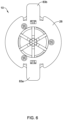
- FIG. 3A illustrates a cross-section of the actuation member 26 with the thrust washer 66.
- FIG. 4 illustrates a portion of the expandable access port 10.
- the distal ends 74 of the tines 16 may include a crimp region 75.
- An end portion 77 of the sleeve 18 may engage the crimp region 75.
- the end portion 77 may be inserted into the crimp region 75 and the crimp region 75 may be crimped. This may help to secure the sleeve 18 to the tines 16.
- FIGS. 5-6 illustrates the expandable access port 10 with the first adjustment mechanism 22a and the second adjustment mechanism 22b detached from the cap 28.
- the cap 28 may include a first attachment region 83a and a second attachment region 83b.
- the first attachment region 83a and the second attachment region 83b allow for a variety of adjustment mechanisms to be releasably coupled thereto.
- the first attachment region 83a and/or the second attachment region 83b may take the form of a flange designed to have an adjustment mechanism (e.g., the first adjustment mechanism 22a, the second adjustment mechanism 22b, or both) releasably attached to the cap 28.
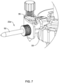
- the adjustment mechanisms 22a/22b may include spring-release attachment/detachment mechanism including a spring or elastic member 33 and a lever member 35 as shown in FIG. 7 .
- the elastic member 33 takes the form of an O-ring that is used as or like a spring to hold down the lever member 35 (e.g., so that adjustment mechanisms 22a/22b can be securely attached to the attachment regions 83a/83b).
- the lever member 35 can be depressed to enlarge or otherwise expand the elastic member 33. This allows the adjustment mechanisms 22a/22b to easily be securely attached/detached from the attachment regions 83a/83b, as desired.
- a clinician may choose to attach a suitable number of adjustment mechanisms to the cap 28 (e.g., the first attachment region 83a and/or the second attachment region 83b).
- the form or type of adjustment mechanism may vary and, in at least some instances, the type of adjustment mechanism may be selected in order to best suit the needs of a particular intervention.
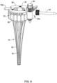
- the first adjustment mechanism 22a may be attached to the first attachment region 83a as shown in FIG. 8 .
- an adjustment mechanism is not attached to the second attachment region 83b.
- FIG. 9 illustrates another adjustment mechanism 22a' attached to the cap 28 (e.g., the first attachment region 83a) of the expandable access port 10.
- the adjustment mechanism 22a' includes the stabilizing bar 52 but does not include a set screw. Other variations are contemplated.
- FIGS. 10-11 illustrates a system 100 that includes the expandable access port 10 along with a holder 56.
- the holder 56 may include a tubular body 58 and a flange 60 disposed along the tubular body 58. In some instances, a nut or grip region 80 may be disposed along the tubular body 58.
- the holder 56 may include a shaft 76 extending from the tubular body 58 and a nose cone 78 may be coupled to the shaft 76.
- the shaft 76 and the nose cone 78 may be designed so that the holder 56 can be inserted into the expandable access port 10 and, when fully inserted, the nose cone 78 may be disposed at the distal end of the expandable access port 10.
- the nose cone 78 may have a generally atraumatic shape.
- the nose cone 78 may include a tapered proximal end region and/or a tapered distal end region. This may allow the nose cone 78 to more easily be inserted into and through the expandable access port 10 and/or more easily removed from the expandable access port 10. When doing so, the expandable access port 10 may partially expand or flex while allowing the nose cone 78 to pass therethrough.
- the nose cone 78 (and/or the holder 56, in general) can be inserted into or removed from the expandable access port 10 without having to shift the expandable conduit 14 to the expanded configuration.
- FIGS. 12-14 illustrate an alternate holder 156 that may be used with the expandable access port 10 described herein.
- the holder 156 may include an obturator 158 and guide 160.
- the obturator 158 may include a lock 180 coupled to the proximal end.
- the lock 180 may have an opening 181 in its distal end face.
- the obturator 158 may have an opening or window 173 extending completely through the obturator 158 transverse to a longitudinal axis x-x.
- the window 173 may allow for a visual confirmation that a pointer tip (not shown) is fully seated within the obturator 158.
- the obturator 158 may have a tapered distal shaft 176 and a nose cone 178.
- the obturator 158 including the distal shaft 176 and nose cone 178, may be a single monolithic element.
- the lock 180 may be coupled to the obturator 158 via a threaded connection.
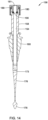
- the proximal end of the obturator 158 may have external threading 159 that mates with internal threading (189; see FIG. 14 ) on the lock 180.
- the guide 160 and obturator 158 may be separate elements with the obturator 158 being insertable into a lumen in the guide 160.
- the guide 160 may be configured to mate with the access port 10.
- the opening 181 in the lock 180 is in communication with a lumen 154 extending partially through the obturator 158, from the proximal end and connecting with the window 173.
- the window 173 is offset from the distal end of the nose cone 178 by about 50 mm to 55 mm, for example 52 mm.
- an O-ring 190 may be positioned within the proximal end of the lumen 154 of the obturator 158, to compress and secure a pointer shaft (not shown).
- the shaft 176 and the nose cone 178 may be designed so that the holder 156 can be inserted into the expandable access port 10 and, when fully inserted, the nose cone 178 may be disposed at the distal end of the expandable access port 10.
- the nose cone 178 may have a generally atraumatic shape.
- the nose cone 178 may include a tapered proximal end region and/or a tapered distal end region.
- the nose cone 178 may have a diameter of 5 mm to 10 mm, for example 6 mm. This may allow the nose cone 178 to more easily be inserted into and through the expandable access port 10 and/or more easily removed from the expandable access port 10.
- the expandable access port 10 may partially expand or flex while allowing the nose cone 178 to pass therethrough. Furthermore, the nose cone 178 (and/or the holder 156, in general) can be inserted into or removed from the expandable access port 10 without having to shift the expandable conduit 14 to the expanded configuration.
- the materials that can be used for the various components of the expandable access port 10 may include those commonly associated with medical devices. For simplicity purposes, the following discussion makes reference to the expandable access port 10. However, this is not intended to limit the devices and methods described herein, as the discussion may be applied to other similar medical devices and/or system disclosed herein.
- the expandable access port 10 may be made from a metal, metal alloy, polymer (some examples of which are disclosed below), a metal-polymer composite, ceramics, combinations thereof, and the like, or other suitable material.
- suitable polymers may include polytetrafluoroethylene (PTFE), ethylene tetrafluoroethylene (ETFE), fluorinated ethylene propylene (FEP), polyoxymethylene (POM, for example, DELRIN ® available from DuPont), polyether block ester, polyurethane (for example, Polyurethane 85A), polypropylene (PP), polyvinylchloride (PVC), polyether-ester (for example, ARNITEL ® available from DSM Engineering Plastics), ether or ester based copolymers (for example, butylene/poly(alkylene ether) phthalate and/or other polyester elastomers such as HYTREL ® available from DuPont), polyamide (for example, DURETHAN ® available from Bayer or
- suitable metals and metal alloys include stainless steel, such as 304V, 304L, and 316LV stainless steel; mild steel; nickel-titanium alloy such as linear-elastic and/or super-elastic nitinol; other nickel alloys such as nickel-chromium-molybdenum alloys (e.g., UNS: N06625 such as INCONEL ® 625, UNS: N06022 such as HASTELLOY ® C-22 ® , UNS: N10276 such as HASTELLOY ® C276 ® , other HASTELLOY ® alloys, and the like), nickel-copper alloys (e.g., UNS: N04400 such as MONEL ® 400, NICKELVAC ® 400, NICORROS ® 400, and the like), nickel-cobalt-chromium-molybdenum alloys (e.g., UNS: R30035 such as MP35-N ® and the like), nickel-co
Landscapes
- Health & Medical Sciences (AREA)
- Surgery (AREA)
- Life Sciences & Earth Sciences (AREA)
- Animal Behavior & Ethology (AREA)
- Public Health (AREA)
- Engineering & Computer Science (AREA)
- Biomedical Technology (AREA)
- Heart & Thoracic Surgery (AREA)
- Medical Informatics (AREA)
- Molecular Biology (AREA)
- Pathology (AREA)
- General Health & Medical Sciences (AREA)
- Nuclear Medicine, Radiotherapy & Molecular Imaging (AREA)
- Veterinary Medicine (AREA)
- Prostheses (AREA)
- Infusion, Injection, And Reservoir Apparatuses (AREA)
- Surgical Instruments (AREA)
- External Artificial Organs (AREA)
- Accommodation For Nursing Or Treatment Tables (AREA)
- Measuring And Recording Apparatus For Diagnosis (AREA)
Claims (12)
- Orifice d'accès expansible (10) comprenant :un boîtier (12) ayant une pluralité de dents (16) couplées à ce dernier ;une rondelle de butée (66) disposée le long du boîtier, la rondelle de butée ayant des régions découpées (68), chaque région découpée (68) étant configurée pour mettre en prise une région d'extrémité proximale (70) d'une de chacune de la pluralité de dents ; etun élément d'actionnement (26) couplé au boîtier, l'élément d'actionnement étant conçu pour déplacer la pluralité de dents entre une première configuration et une configuration expansée.
- Orifice d'accès expansible selon la revendication 1, dans lequel la région d'extrémité proximale de la pluralité de dents a une surface coudée (72).
- Orifice d'accès expansible selon la revendication 2, dans lequel l'élément d'actionnement comprend une surface d'actionnement (86) conçue pour mettre en prise la surface coudée.
- Orifice d'accès expansible selon l'une quelconque des revendications 1 à 3, dans lequel la rondelle de butée est disposée entre le boîtier et l'élément d'actionnement.
- Orifice d'accès expansible selon l'une quelconque des revendications 1 à 4, dans lequel le boîtier comprend une région filetée (64).
- Orifice d'accès expansible selon la revendication 5, dans lequel l'élément d'actionnement comprend un écrou (26) mis en prise, par filetage, avec la région filetée (64).
- Orifice d'accès expansible selon l'une quelconque des revendications 1 à 6, comprenant en outre un manchon (18) s'étendant le long d'au moins certaines de la pluralité de dents (16).
- Orifice d'accès expansible selon la revendication 7, dans lequel le manchon comprend un élastomère biocompatible.
- Orifice d'accès expansible selon la revendication 7, dans lequel le manchon peut s'allonger jusqu'à 400 - 1200%.
- Orifice d'accès expansible selon la revendication 7, dans lequel le manchon peut s'allonger jusqu'à 600 - 1000%.
- Orifice d'accès expansible selon la revendication 7, dans lequel le manchon peut s'allonger jusqu'à 800%.
- Système comprenant :l'orifice d'accès expansible (10) selon l'une quelconque des revendications 1 à 11 ;un obturateur (158) comprenant un arbre (176) et un cône de nez (178) ; etun guide (160) ayant une lumière configurée pour recevoir l'obturateur, le guide étant configuré pour se coupler avec le boîtier (12).
Priority Applications (1)
| Application Number | Priority Date | Filing Date | Title |
|---|---|---|---|
| EP25178933.5A EP4643797A3 (fr) | 2020-01-22 | 2021-01-22 | Dispositif médical pour accéder au système nerveux central |
Applications Claiming Priority (2)
| Application Number | Priority Date | Filing Date | Title |
|---|---|---|---|
| US202062964394P | 2020-01-22 | 2020-01-22 | |
| PCT/US2021/014672 WO2021150927A1 (fr) | 2020-01-22 | 2021-01-22 | Dispositif médical pour accéder au système nerveux central |
Related Child Applications (1)
| Application Number | Title | Priority Date | Filing Date |
|---|---|---|---|
| EP25178933.5A Division EP4643797A3 (fr) | 2020-01-22 | 2021-01-22 | Dispositif médical pour accéder au système nerveux central |
Publications (2)
| Publication Number | Publication Date |
|---|---|
| EP4093305A1 EP4093305A1 (fr) | 2022-11-30 |
| EP4093305B1 true EP4093305B1 (fr) | 2025-05-28 |
Family
ID=74661482
Family Applications (2)
| Application Number | Title | Priority Date | Filing Date |
|---|---|---|---|
| EP21706097.9A Active EP4093305B1 (fr) | 2020-01-22 | 2021-01-22 | Dispositif médical pour accéder au système nerveux central |
| EP25178933.5A Pending EP4643797A3 (fr) | 2020-01-22 | 2021-01-22 | Dispositif médical pour accéder au système nerveux central |
Family Applications After (1)
| Application Number | Title | Priority Date | Filing Date |
|---|---|---|---|
| EP25178933.5A Pending EP4643797A3 (fr) | 2020-01-22 | 2021-01-22 | Dispositif médical pour accéder au système nerveux central |
Country Status (8)
| Country | Link |
|---|---|
| US (3) | US11974775B2 (fr) |
| EP (2) | EP4093305B1 (fr) |
| JP (1) | JP7419545B2 (fr) |
| CN (1) | CN115348843B (fr) |
| AU (2) | AU2021209682B2 (fr) |
| CA (1) | CA3168250A1 (fr) |
| ES (1) | ES3034735T3 (fr) |
| WO (1) | WO2021150927A1 (fr) |
Citations (1)
| Publication number | Priority date | Publication date | Assignee | Title |
|---|---|---|---|---|
| EP1970012B1 (fr) * | 2007-03-14 | 2011-11-02 | AB Medica S.p.A. | Trocart pour chirurgie thoracique |
Family Cites Families (88)
| Publication number | Priority date | Publication date | Assignee | Title |
|---|---|---|---|---|
| US380745A (en) * | 1888-04-10 | Speculum | ||
| US3804750A (en) | 1972-12-22 | 1974-04-16 | Atlantic Richfield Co | Shale oil treatment |
| US4130113A (en) | 1976-12-15 | 1978-12-19 | Richards Manufacturing Co., Inc. | Retractor |
| US5865728A (en) | 1991-05-29 | 1999-02-02 | Origin Medsystems, Inc. | Method of using an endoscopic inflatable lifting apparatus to create an anatomic working space |
| US5382230A (en) | 1991-12-16 | 1995-01-17 | Thomas Jefferson University | Vascular access sheath for interventional devices |
| US7553290B1 (en) | 1999-06-04 | 2009-06-30 | Medtronic Ps Medical, Inc. | Subdural evacuating port aspiration system |
| US7694821B1 (en) | 1999-06-04 | 2010-04-13 | Medtronic Ps Medical, Inc. | Subdural evacuating port system |
| US6923799B1 (en) | 1999-06-04 | 2005-08-02 | Wilson T. Asfora | Subdural evacuating port system |
| US7660621B2 (en) | 2000-04-07 | 2010-02-09 | Medtronic, Inc. | Medical device introducer |
| DE20015813U1 (de) * | 2000-09-12 | 2001-03-15 | Condor GmbH Medicaltechnik, 33129 Delbrück | Schnellspannklammer für eine Wundspreizvorrichtung |
| US6730021B2 (en) | 2001-11-07 | 2004-05-04 | Computer Motion, Inc. | Tissue spreader with force measurement, force indication or force limitation |
| US6945933B2 (en) | 2002-06-26 | 2005-09-20 | Sdgi Holdings, Inc. | Instruments and methods for minimally invasive tissue retraction and surgery |
| US7850608B2 (en) | 2002-10-25 | 2010-12-14 | K2M, Inc. | Minimal incision maximal access MIS spine instrumentation and method |
| US7645232B2 (en) | 2003-05-16 | 2010-01-12 | Zimmer Spine, Inc. | Access device for minimally invasive surgery |
| US7481766B2 (en) | 2003-08-14 | 2009-01-27 | Synthes (U.S.A.) | Multiple-blade retractor |
| EP1667584B1 (fr) | 2003-08-26 | 2008-12-10 | Zimmer Spine, Inc. | Systemes d'acces permettant les operations chirurgicales avec un degre minimal d'invasivite |
| US7182729B2 (en) | 2003-09-18 | 2007-02-27 | Stryker Spine | Surgical retractor with removable scissor arms |
| FR2863504B1 (fr) * | 2003-12-10 | 2006-09-29 | Claude Mialhe | Valve pour instrument chirurgical ou medical |
| AU2004303424C1 (en) | 2003-12-18 | 2009-11-05 | Depuy Spine, Inc. | Surgical retractor systems, illuminated cannulae, and methods of use |
| US7195592B2 (en) * | 2004-01-27 | 2007-03-27 | Sundaram Ravikumar | Surgical retractor apparatus for use with a surgical port |
| US7435219B2 (en) | 2004-03-25 | 2008-10-14 | Depuy Spine, Inc. | Surgical retractor positioning device |
| JP4868602B2 (ja) | 2004-04-05 | 2012-02-01 | タイコ・ヘルスケア・グループ・リミテッド・パートナーシップ | 外科用手接近装置 |
| US7150714B2 (en) | 2004-06-14 | 2006-12-19 | Ebi, L.P. | Minimally invasive surgical spinal exposure system |
| US8152837B2 (en) | 2004-10-20 | 2012-04-10 | The Board Of Trustees Of The Leland Stanford Junior University | Systems and methods for posterior dynamic stabilization of the spine |
| US9161820B2 (en) | 2004-10-28 | 2015-10-20 | Nico Corporation | Surgical access assembly and method of using same |
| US9387010B2 (en) | 2004-10-28 | 2016-07-12 | Nico Corporation | Surgical access assembly and method of using same |
| US9216015B2 (en) | 2004-10-28 | 2015-12-22 | Vycor Medical, Inc. | Apparatus and methods for performing brain surgery |
| US9265523B2 (en) | 2011-10-24 | 2016-02-23 | Nico Corporation | Surgical access system with navigation element and method of using same |
| US9770261B2 (en) | 2004-10-28 | 2017-09-26 | Nico Corporation | Surgical access assembly and method of using same |
| US9186175B2 (en) | 2004-10-28 | 2015-11-17 | Nico Corporation | Surgical access assembly and method of using same |
| US7594888B2 (en) | 2004-10-29 | 2009-09-29 | Depuy Spine, Inc. | Expandable ports and methods for minimally invasive surgery |
| US8579809B2 (en) | 2004-12-23 | 2013-11-12 | Symmetry Medical Manufacturing, Inc. | Radially expanding surgical retractor |
| US7473223B2 (en) | 2005-02-07 | 2009-01-06 | Peter Edward Fetzer | Push-button activated grasper for surgical retractor |
| US7374534B2 (en) | 2005-03-09 | 2008-05-20 | Dalton Brian E | Retractor and method for percutaneous tissue retraction and surgery |
| US20060287583A1 (en) | 2005-06-17 | 2006-12-21 | Pool Cover Corporation | Surgical access instruments for use with delicate tissues |
| EP1906810B1 (fr) | 2005-06-22 | 2016-04-27 | Vycor Medical, Inc. | Instruments d'accès chirurgical pour la chirurgie rachidienne ou orthopédique |
| US8105236B2 (en) | 2005-07-11 | 2012-01-31 | Kyphon Sarl | Surgical access device, system, and methods of use |
| US20070060939A1 (en) * | 2005-09-02 | 2007-03-15 | Zimmer Spine, Inc. | Expandable and retractable cannula |
| EP1959844B1 (fr) | 2005-12-15 | 2011-07-20 | Microdel Idea Center Ltd. | Rétracteur radialement extensible amélioré pour chirurgie peu invasive |
| US7758501B2 (en) | 2006-01-04 | 2010-07-20 | Depuy Spine, Inc. | Surgical reactors and methods of minimally invasive surgery |
| US7981031B2 (en) | 2006-01-04 | 2011-07-19 | Depuy Spine, Inc. | Surgical access devices and methods of minimally invasive surgery |
| US7985179B2 (en) | 2006-01-23 | 2011-07-26 | Pioneer Surgical Technology | Retraction apparatus and method of use |
| US8876687B2 (en) | 2006-03-08 | 2014-11-04 | Zimmer Spine, Inc. | Surgical retractor and retractor assembly |
| US8992425B2 (en) | 2006-06-06 | 2015-03-31 | Globus Medical, Inc. | Surgical retractor system |
| US7935053B2 (en) | 2006-06-06 | 2011-05-03 | Globus Medical, Inc | Surgical Retractor System |
| US7892174B2 (en) | 2006-07-19 | 2011-02-22 | Zimmer Spine, Inc. | Surgical access system and method of using the same |
| US7931589B2 (en) | 2006-11-09 | 2011-04-26 | Ebi, Llc | Surgical retractor device and related methods |
| US7896088B2 (en) | 2007-12-21 | 2011-03-01 | Schlumberger Technology Corporation | Wellsite systems utilizing deployable structure |
| US8733453B2 (en) | 2007-12-21 | 2014-05-27 | Schlumberger Technology Corporation | Expandable structure for deployment in a well |
| US8291781B2 (en) | 2007-12-21 | 2012-10-23 | Schlumberger Technology Corporation | System and methods for actuating reversibly expandable structures |
| US8992558B2 (en) | 2008-12-18 | 2015-03-31 | Osteomed, Llc | Lateral access system for the lumbar spine |
| US8152720B2 (en) | 2009-08-05 | 2012-04-10 | Thomas Stuart Loftus | Retracto component system and method of using same |
| US7967790B2 (en) | 2009-09-01 | 2011-06-28 | Pacesetter, Inc. | Hemostasis valve with iris seal |
| US8454504B2 (en) | 2010-02-24 | 2013-06-04 | Meni-Med Ltd | Surgical retractor |
| US8974380B2 (en) * | 2010-02-24 | 2015-03-10 | Meni-Med Ltd | Surgical retractor |
| US8409089B2 (en) | 2010-02-24 | 2013-04-02 | Meni-Med Ltd. | Surgical retractor |
| US8663102B2 (en) | 2010-02-24 | 2014-03-04 | Meni-Med Ltd. | Surgical retractor |
| US9179903B2 (en) | 2010-03-11 | 2015-11-10 | Globus Medical, Inc. | Tissue retractor and method of use |
| US8353826B2 (en) | 2010-03-11 | 2013-01-15 | Globus Medical, Inc. | Tissue retractor and method of use |
| BR112012026160A2 (pt) | 2010-04-14 | 2017-08-22 | Osteomed Llc | Sistema para abertura de uma passaem em um corpo |
| PL2558154T3 (pl) | 2010-04-16 | 2020-11-30 | Clearpoint Neuro, Inc. | Systemy chirurgiczne MRI zawierające kaniule chirurgiczne kompatybilne z MRI do transferu substancji do i/lub od pacjenta |
| WO2012050973A1 (fr) | 2010-09-29 | 2012-04-19 | Ams Research Corporation | Systèmes, outils et procédés pour le traitement d'affections pelviennes |
| CN201824152U (zh) * | 2010-10-16 | 2011-05-11 | 嘉兴永佳精密机械制造有限公司 | 一种筒夹锁紧机构 |
| CN204218948U (zh) | 2011-08-31 | 2015-03-25 | 兰克斯股份有限公司 | 一种外科手术牵开器 |
| US8961535B2 (en) | 2011-10-25 | 2015-02-24 | Medtronic Navigation, Inc. | Method and apparatus for securing a guide tube |
| US8821394B2 (en) | 2012-03-30 | 2014-09-02 | DePuy Synthes Products, LLC | Methods and devices for tissue retraction |
| US9757147B2 (en) | 2012-04-11 | 2017-09-12 | Nico Corporation | Surgical access system with navigation element and method of using same |
| US9629523B2 (en) | 2012-06-27 | 2017-04-25 | Camplex, Inc. | Binocular viewing assembly for a surgical visualization system |
| US9113854B2 (en) * | 2012-10-22 | 2015-08-25 | Alan G Ellman | Tissue retractor |
| US9693761B2 (en) | 2012-10-24 | 2017-07-04 | Blackstone Medical, Inc. | Retractor device and method |
| US9855027B2 (en) | 2012-10-24 | 2018-01-02 | Blackstone Medical, Inc. | Retractor device and method |
| US10022520B2 (en) | 2012-12-17 | 2018-07-17 | Nico Corporation | Surgical access system |
| US9072501B2 (en) | 2013-03-15 | 2015-07-07 | Regents Of The University Of Minnesota | Micro-orifice surgical access system |
| US10548630B2 (en) | 2014-02-11 | 2020-02-04 | Vanderbilt University | System, method, and apparatus for configuration, design, and operation of an active cannula robot |
| CN106659375A (zh) | 2014-05-13 | 2017-05-10 | Vycor医学有限责任公司 | 用于手术导引器的引导系统安装件 |
| US9675333B2 (en) * | 2014-06-19 | 2017-06-13 | Kyphon SÀRL | Cannula with flexible holder and methods of use |
| US20170215860A1 (en) | 2014-07-23 | 2017-08-03 | Robert TRIMARCHE | Modifications to access ports for minimally invasive neuro surgery |
| US10456061B2 (en) | 2014-11-12 | 2019-10-29 | Nico Corporation | Holding arrangement for a surgical access system |
| US10357280B2 (en) | 2015-04-30 | 2019-07-23 | Nico Corporation | Navigating introducer for tissue access system |
| US10828123B2 (en) | 2015-07-02 | 2020-11-10 | Nico Corporation | Navigation stylet for a tissue access system |
| US10543057B2 (en) | 2016-03-15 | 2020-01-28 | Nico Corporation | Selectively lockable holding arrangement for a surgical access system |
| US10765450B2 (en) | 2016-03-15 | 2020-09-08 | Nico Corporation | Selectively lockable holding arrangement for a surgical access system |
| JP7026645B2 (ja) | 2016-03-17 | 2022-02-28 | トライス メディカル インコーポレイテッド | 凝血塊の排出及び視覚化装置及び使用方法 |
| US10543016B2 (en) | 2016-11-07 | 2020-01-28 | Vycor Medical, Inc. | Surgical introducer with guidance system receptacle |
| US10376258B2 (en) | 2016-11-07 | 2019-08-13 | Vycor Medical, Inc. | Surgical introducer with guidance system receptacle |
| CA2993590A1 (fr) * | 2017-09-06 | 2019-03-06 | Xpan Inc. | Systeme de canule extensible radialement |
| JP7231637B2 (ja) | 2018-02-15 | 2023-03-01 | ミネトロニクス ニューロ インコーポレイテッド | 中枢神経系にアクセスするための医療用デバイス |
| US20240008896A1 (en) * | 2022-07-06 | 2024-01-11 | Vycor Medical, Inc. | Expandable surgical access port |
-
2021
- 2021-01-22 EP EP21706097.9A patent/EP4093305B1/fr active Active
- 2021-01-22 JP JP2022544199A patent/JP7419545B2/ja active Active
- 2021-01-22 CA CA3168250A patent/CA3168250A1/fr active Pending
- 2021-01-22 WO PCT/US2021/014672 patent/WO2021150927A1/fr not_active Ceased
- 2021-01-22 AU AU2021209682A patent/AU2021209682B2/en active Active
- 2021-01-22 US US17/155,972 patent/US11974775B2/en active Active
- 2021-01-22 EP EP25178933.5A patent/EP4643797A3/fr active Pending
- 2021-01-22 CN CN202180010222.XA patent/CN115348843B/zh active Active
- 2021-01-22 ES ES21706097T patent/ES3034735T3/es active Active
-
2024
- 2024-04-08 US US18/629,018 patent/US12527598B2/en active Active
- 2024-06-07 AU AU2024203882A patent/AU2024203882B2/en active Active
-
2025
- 2025-12-22 US US19/428,832 patent/US20260114898A1/en active Pending
Patent Citations (1)
| Publication number | Priority date | Publication date | Assignee | Title |
|---|---|---|---|---|
| EP1970012B1 (fr) * | 2007-03-14 | 2011-11-02 | AB Medica S.p.A. | Trocart pour chirurgie thoracique |
Also Published As
| Publication number | Publication date |
|---|---|
| AU2021209682B2 (en) | 2024-03-14 |
| AU2021209682A1 (en) | 2022-09-15 |
| WO2021150927A1 (fr) | 2021-07-29 |
| US20240252207A1 (en) | 2024-08-01 |
| CN115348843B (zh) | 2026-01-16 |
| CN115348843A (zh) | 2022-11-15 |
| US12527598B2 (en) | 2026-01-20 |
| CA3168250A1 (fr) | 2021-07-29 |
| EP4093305A1 (fr) | 2022-11-30 |
| US11974775B2 (en) | 2024-05-07 |
| JP7419545B2 (ja) | 2024-01-22 |
| EP4643797A3 (fr) | 2026-01-21 |
| EP4643797A2 (fr) | 2025-11-05 |
| AU2024203882B2 (en) | 2026-01-08 |
| AU2024203882A1 (en) | 2024-06-27 |
| US20210220011A1 (en) | 2021-07-22 |
| JP2023511890A (ja) | 2023-03-23 |
| US20260114898A1 (en) | 2026-04-30 |
| ES3034735T3 (en) | 2025-08-22 |
Similar Documents
| Publication | Publication Date | Title |
|---|---|---|
| US12232765B2 (en) | Medical device for accessing the central nervous system | |
| EP3562545B1 (fr) | Dispositifs et procédés de pose de dispositifs cardiaques sans fil | |
| EP2773272B1 (fr) | Dispositif médical rotatif | |
| EP4093305B1 (fr) | Dispositif médical pour accéder au système nerveux central | |
| US20240268830A1 (en) | Multi-part medical devices with locking mechanism | |
| US20250057537A1 (en) | Delivery device for occlusive implants | |
| US20260076678A1 (en) | Medical devices for use in delivering occlusive implants | |
| US20230149670A1 (en) | Medical device for septal crossing with trapping features | |
| WO2025019657A1 (fr) | Dispositif de pose d'implants occlusifs | |
| WO2025015013A1 (fr) | Dispositif de pose d'implants occlusifs | |
| WO2025038808A1 (fr) | Dispositif de pose d'implants occlusifs | |
| WO2025096414A1 (fr) | Dispositif de pose d'implants occlusifs |
Legal Events
| Date | Code | Title | Description |
|---|---|---|---|
| STAA | Information on the status of an ep patent application or granted ep patent |
Free format text: STATUS: UNKNOWN |
|
| STAA | Information on the status of an ep patent application or granted ep patent |
Free format text: STATUS: THE INTERNATIONAL PUBLICATION HAS BEEN MADE |
|
| PUAI | Public reference made under article 153(3) epc to a published international application that has entered the european phase |
Free format text: ORIGINAL CODE: 0009012 |
|
| STAA | Information on the status of an ep patent application or granted ep patent |
Free format text: STATUS: REQUEST FOR EXAMINATION WAS MADE |
|
| 17P | Request for examination filed |
Effective date: 20220805 |
|
| AK | Designated contracting states |
Kind code of ref document: A1 Designated state(s): AL AT BE BG CH CY CZ DE DK EE ES FI FR GB GR HR HU IE IS IT LI LT LU LV MC MK MT NL NO PL PT RO RS SE SI SK SM TR |
|
| DAV | Request for validation of the european patent (deleted) | ||
| DAX | Request for extension of the european patent (deleted) | ||
| STAA | Information on the status of an ep patent application or granted ep patent |
Free format text: STATUS: EXAMINATION IS IN PROGRESS |
|
| 17Q | First examination report despatched |
Effective date: 20240429 |
|
| GRAP | Despatch of communication of intention to grant a patent |
Free format text: ORIGINAL CODE: EPIDOSNIGR1 |
|
| STAA | Information on the status of an ep patent application or granted ep patent |
Free format text: STATUS: GRANT OF PATENT IS INTENDED |
|
| INTG | Intention to grant announced |
Effective date: 20241218 |
|
| GRAS | Grant fee paid |
Free format text: ORIGINAL CODE: EPIDOSNIGR3 |
|
| GRAA | (expected) grant |
Free format text: ORIGINAL CODE: 0009210 |
|
| STAA | Information on the status of an ep patent application or granted ep patent |
Free format text: STATUS: THE PATENT HAS BEEN GRANTED |
|
| AK | Designated contracting states |
Kind code of ref document: B1 Designated state(s): AL AT BE BG CH CY CZ DE DK EE ES FI FR GB GR HR HU IE IS IT LI LT LU LV MC MK MT NL NO PL PT RO RS SE SI SK SM TR |
|
| P01 | Opt-out of the competence of the unified patent court (upc) registered |
Free format text: CASE NUMBER: APP_19140/2025 Effective date: 20250422 |
|
| REG | Reference to a national code |
Ref country code: GB Ref legal event code: FG4D |
|
| REG | Reference to a national code |
Ref country code: CH Ref legal event code: EP |
|
| REG | Reference to a national code |
Ref country code: IE Ref legal event code: FG4D Ref country code: DE Ref legal event code: R096 Ref document number: 602021031404 Country of ref document: DE |
|
| REG | Reference to a national code |
Ref country code: ES Ref legal event code: FG2A Ref document number: 3034735 Country of ref document: ES Kind code of ref document: T3 Effective date: 20250822 |
|
| REG | Reference to a national code |
Ref country code: DE Ref legal event code: R081 Ref document number: 602021031404 Country of ref document: DE Owner name: MINNETRONIX NEURO, INC., EXCELSIOR, US Free format text: FORMER OWNER: MINNETRONIX NEURO, INC., ST. PAUL, MN, US Ref country code: NL Ref legal event code: MP Effective date: 20250528 Ref country code: DE Ref legal event code: R081 Ref document number: 602021031404 Country of ref document: DE Owner name: PHARAOH NEURO, INC. (N.D.GES.D.STAATES DELAWAR, US Free format text: FORMER OWNER: MINNETRONIX NEURO, INC., ST. PAUL, MN, US |
|
| PG25 | Lapsed in a contracting state [announced via postgrant information from national office to epo] |
Ref country code: FI Free format text: LAPSE BECAUSE OF FAILURE TO SUBMIT A TRANSLATION OF THE DESCRIPTION OR TO PAY THE FEE WITHIN THE PRESCRIBED TIME-LIMIT Effective date: 20250528 |
|
| REG | Reference to a national code |
Ref country code: LT Ref legal event code: MG9D |
|
| PG25 | Lapsed in a contracting state [announced via postgrant information from national office to epo] |
Ref country code: NO Free format text: LAPSE BECAUSE OF FAILURE TO SUBMIT A TRANSLATION OF THE DESCRIPTION OR TO PAY THE FEE WITHIN THE PRESCRIBED TIME-LIMIT Effective date: 20250828 Ref country code: GR Free format text: LAPSE BECAUSE OF FAILURE TO SUBMIT A TRANSLATION OF THE DESCRIPTION OR TO PAY THE FEE WITHIN THE PRESCRIBED TIME-LIMIT Effective date: 20250829 |
|
| PG25 | Lapsed in a contracting state [announced via postgrant information from national office to epo] |
Ref country code: PL Free format text: LAPSE BECAUSE OF FAILURE TO SUBMIT A TRANSLATION OF THE DESCRIPTION OR TO PAY THE FEE WITHIN THE PRESCRIBED TIME-LIMIT Effective date: 20250528 Ref country code: NL Free format text: LAPSE BECAUSE OF FAILURE TO SUBMIT A TRANSLATION OF THE DESCRIPTION OR TO PAY THE FEE WITHIN THE PRESCRIBED TIME-LIMIT Effective date: 20250528 |
|
| RAP4 | Party data changed (patent owner data changed or rights of a patent transferred) |
Owner name: MINNETRONIX NEURO, INC. |
|
| PG25 | Lapsed in a contracting state [announced via postgrant information from national office to epo] |
Ref country code: BG Free format text: LAPSE BECAUSE OF FAILURE TO SUBMIT A TRANSLATION OF THE DESCRIPTION OR TO PAY THE FEE WITHIN THE PRESCRIBED TIME-LIMIT Effective date: 20250528 |
|
| PG25 | Lapsed in a contracting state [announced via postgrant information from national office to epo] |
Ref country code: HR Free format text: LAPSE BECAUSE OF FAILURE TO SUBMIT A TRANSLATION OF THE DESCRIPTION OR TO PAY THE FEE WITHIN THE PRESCRIBED TIME-LIMIT Effective date: 20250528 |
|
| PG25 | Lapsed in a contracting state [announced via postgrant information from national office to epo] |
Ref country code: RS Free format text: LAPSE BECAUSE OF FAILURE TO SUBMIT A TRANSLATION OF THE DESCRIPTION OR TO PAY THE FEE WITHIN THE PRESCRIBED TIME-LIMIT Effective date: 20250828 |
|
| PG25 | Lapsed in a contracting state [announced via postgrant information from national office to epo] |
Ref country code: IS Free format text: LAPSE BECAUSE OF FAILURE TO SUBMIT A TRANSLATION OF THE DESCRIPTION OR TO PAY THE FEE WITHIN THE PRESCRIBED TIME-LIMIT Effective date: 20250928 |
|
| PG25 | Lapsed in a contracting state [announced via postgrant information from national office to epo] |
Ref country code: LV Free format text: LAPSE BECAUSE OF FAILURE TO SUBMIT A TRANSLATION OF THE DESCRIPTION OR TO PAY THE FEE WITHIN THE PRESCRIBED TIME-LIMIT Effective date: 20250528 |
|
| REG | Reference to a national code |
Ref country code: CH Ref legal event code: W10 Free format text: ST27 STATUS EVENT CODE: U-0-0-W10-W00 (AS PROVIDED BY THE NATIONAL OFFICE) Effective date: 20251112 |
|
| REG | Reference to a national code |
Ref country code: DE Ref legal event code: R081 Ref document number: 602021031404 Country of ref document: DE Owner name: PHARAOH NEURO, INC. (N.D.GES.D.STAATES DELAWAR, US Free format text: FORMER OWNER: MINNETRONIX NEURO, INC., EXCELSIOR, MN, US |
|
| RAP4 | Party data changed (patent owner data changed or rights of a patent transferred) |
Owner name: PHARAOH NEURO, INC. |
|
| REG | Reference to a national code |
Ref country code: AT Ref legal event code: MK05 Ref document number: 1798183 Country of ref document: AT Kind code of ref document: T Effective date: 20250528 |
|
| PG25 | Lapsed in a contracting state [announced via postgrant information from national office to epo] |
Ref country code: AT Free format text: LAPSE BECAUSE OF FAILURE TO SUBMIT A TRANSLATION OF THE DESCRIPTION OR TO PAY THE FEE WITHIN THE PRESCRIBED TIME-LIMIT Effective date: 20250528 Ref country code: DK Free format text: LAPSE BECAUSE OF FAILURE TO SUBMIT A TRANSLATION OF THE DESCRIPTION OR TO PAY THE FEE WITHIN THE PRESCRIBED TIME-LIMIT Effective date: 20250528 Ref country code: SM Free format text: LAPSE BECAUSE OF FAILURE TO SUBMIT A TRANSLATION OF THE DESCRIPTION OR TO PAY THE FEE WITHIN THE PRESCRIBED TIME-LIMIT Effective date: 20250528 |
|
| PG25 | Lapsed in a contracting state [announced via postgrant information from national office to epo] |
Ref country code: CZ Free format text: LAPSE BECAUSE OF FAILURE TO SUBMIT A TRANSLATION OF THE DESCRIPTION OR TO PAY THE FEE WITHIN THE PRESCRIBED TIME-LIMIT Effective date: 20250528 |
|
| PG25 | Lapsed in a contracting state [announced via postgrant information from national office to epo] |
Ref country code: EE Free format text: LAPSE BECAUSE OF FAILURE TO SUBMIT A TRANSLATION OF THE DESCRIPTION OR TO PAY THE FEE WITHIN THE PRESCRIBED TIME-LIMIT Effective date: 20250528 |
|
| PG25 | Lapsed in a contracting state [announced via postgrant information from national office to epo] |
Ref country code: SK Free format text: LAPSE BECAUSE OF FAILURE TO SUBMIT A TRANSLATION OF THE DESCRIPTION OR TO PAY THE FEE WITHIN THE PRESCRIBED TIME-LIMIT Effective date: 20250528 |
|
| REG | Reference to a national code |
Ref country code: DE Ref legal event code: R097 Ref document number: 602021031404 Country of ref document: DE |
|
| PLBE | No opposition filed within time limit |
Free format text: ORIGINAL CODE: 0009261 |
|
| STAA | Information on the status of an ep patent application or granted ep patent |
Free format text: STATUS: NO OPPOSITION FILED WITHIN TIME LIMIT |
|
| PGFP | Annual fee paid to national office [announced via postgrant information from national office to epo] |
Ref country code: GB Payment date: 20260128 Year of fee payment: 6 |
|
| REG | Reference to a national code |
Ref country code: CH Ref legal event code: L10 Free format text: ST27 STATUS EVENT CODE: U-0-0-L10-L00 (AS PROVIDED BY THE NATIONAL OFFICE) Effective date: 20260409 |
|
| PGFP | Annual fee paid to national office [announced via postgrant information from national office to epo] |
Ref country code: ES Payment date: 20260210 Year of fee payment: 6 |
|
| PGFP | Annual fee paid to national office [announced via postgrant information from national office to epo] |
Ref country code: DE Payment date: 20260129 Year of fee payment: 6 |
|
| PGFP | Annual fee paid to national office [announced via postgrant information from national office to epo] |
Ref country code: IT Payment date: 20260122 Year of fee payment: 6 |
|
| PGFP | Annual fee paid to national office [announced via postgrant information from national office to epo] |
Ref country code: FR Payment date: 20260126 Year of fee payment: 6 |