EP4093492B1 - Implantierbare medizinprodukte mit einsetzbar abnehmbaren elementen - Google Patents
Implantierbare medizinprodukte mit einsetzbar abnehmbaren elementen Download PDFInfo
- Publication number
- EP4093492B1 EP4093492B1 EP21705794.2A EP21705794A EP4093492B1 EP 4093492 B1 EP4093492 B1 EP 4093492B1 EP 21705794 A EP21705794 A EP 21705794A EP 4093492 B1 EP4093492 B1 EP 4093492B1
- Authority
- EP
- European Patent Office
- Prior art keywords
- housing
- implantable
- cavity
- elements
- implantable element
- Prior art date
- Legal status (The legal status is an assumption and is not a legal conclusion. Google has not performed a legal analysis and makes no representation as to the accuracy of the status listed.)
- Active
Links
Images



Classifications
-
- A—HUMAN NECESSITIES
- A61—MEDICAL OR VETERINARY SCIENCE; HYGIENE
- A61B—DIAGNOSIS; SURGERY; IDENTIFICATION
- A61B90/00—Instruments, implements or accessories specially adapted for surgery or diagnosis and not covered by any of the groups A61B1/00 - A61B50/00, e.g. for luxation treatment or for protecting wound edges
- A61B90/39—Markers, e.g. radio-opaque or breast lesions markers
-
- A—HUMAN NECESSITIES
- A61—MEDICAL OR VETERINARY SCIENCE; HYGIENE
- A61M—DEVICES FOR INTRODUCING MEDIA INTO, OR ONTO, THE BODY; DEVICES FOR TRANSDUCING BODY MEDIA OR FOR TAKING MEDIA FROM THE BODY; DEVICES FOR PRODUCING OR ENDING SLEEP OR STUPOR
- A61M39/00—Tubes, tube connectors, tube couplings, valves, access sites or the like, specially adapted for medical use
- A61M39/02—Access sites
- A61M39/0247—Semi-permanent or permanent transcutaneous or percutaneous access sites to the inside of the body
-
- A—HUMAN NECESSITIES
- A61—MEDICAL OR VETERINARY SCIENCE; HYGIENE
- A61N—ELECTROTHERAPY; MAGNETOTHERAPY; RADIATION THERAPY; ULTRASOUND THERAPY
- A61N1/00—Electrotherapy; Circuits therefor
- A61N1/02—Details
- A61N1/04—Electrodes
- A61N1/05—Electrodes for implantation or insertion into the body, e.g. heart electrode
-
- A—HUMAN NECESSITIES
- A61—MEDICAL OR VETERINARY SCIENCE; HYGIENE
- A61N—ELECTROTHERAPY; MAGNETOTHERAPY; RADIATION THERAPY; ULTRASOUND THERAPY
- A61N1/00—Electrotherapy; Circuits therefor
- A61N1/18—Applying electric currents by contact electrodes
- A61N1/32—Applying electric currents by contact electrodes alternating or intermittent currents
- A61N1/36—Applying electric currents by contact electrodes alternating or intermittent currents for stimulation
- A61N1/36036—Applying electric currents by contact electrodes alternating or intermittent currents for stimulation of the outer, middle or inner ear
- A61N1/36038—Cochlear stimulation
-
- A—HUMAN NECESSITIES
- A61—MEDICAL OR VETERINARY SCIENCE; HYGIENE
- A61N—ELECTROTHERAPY; MAGNETOTHERAPY; RADIATION THERAPY; ULTRASOUND THERAPY
- A61N1/00—Electrotherapy; Circuits therefor
- A61N1/18—Applying electric currents by contact electrodes
- A61N1/32—Applying electric currents by contact electrodes alternating or intermittent currents
- A61N1/36—Applying electric currents by contact electrodes alternating or intermittent currents for stimulation
- A61N1/372—Arrangements in connection with the implantation of stimulators
- A61N1/37211—Means for communicating with stimulators
- A61N1/37252—Details of algorithms or data aspects of communication system, e.g. handshaking, transmitting specific data or segmenting data
- A61N1/37264—Changing the program; Upgrading firmware
-
- A—HUMAN NECESSITIES
- A61—MEDICAL OR VETERINARY SCIENCE; HYGIENE
- A61N—ELECTROTHERAPY; MAGNETOTHERAPY; RADIATION THERAPY; ULTRASOUND THERAPY
- A61N1/00—Electrotherapy; Circuits therefor
- A61N1/18—Applying electric currents by contact electrodes
- A61N1/32—Applying electric currents by contact electrodes alternating or intermittent currents
- A61N1/36—Applying electric currents by contact electrodes alternating or intermittent currents for stimulation
- A61N1/372—Arrangements in connection with the implantation of stimulators
- A61N1/375—Constructional arrangements, e.g. casings
- A61N1/37514—Brain implants
-
- H—ELECTRICITY
- H04—ELECTRIC COMMUNICATION TECHNIQUE
- H04R—LOUDSPEAKERS, MICROPHONES, GRAMOPHONE PICK-UPS OR LIKE ACOUSTIC ELECTROMECHANICAL TRANSDUCERS; ELECTRIC HEARING AIDS; PUBLIC ADDRESS SYSTEMS
- H04R25/00—Electric hearing aids
- H04R25/60—Mounting or interconnection of hearing aid parts, e.g. inside tips, housings or to ossicles
-
- A—HUMAN NECESSITIES
- A61—MEDICAL OR VETERINARY SCIENCE; HYGIENE
- A61B—DIAGNOSIS; SURGERY; IDENTIFICATION
- A61B90/00—Instruments, implements or accessories specially adapted for surgery or diagnosis and not covered by any of the groups A61B1/00 - A61B50/00, e.g. for luxation treatment or for protecting wound edges
- A61B90/39—Markers, e.g. radio-opaque or breast lesions markers
- A61B2090/3954—Markers, e.g. radio-opaque or breast lesions markers magnetic, e.g. NMR or MRI
-
- A—HUMAN NECESSITIES
- A61—MEDICAL OR VETERINARY SCIENCE; HYGIENE
- A61B—DIAGNOSIS; SURGERY; IDENTIFICATION
- A61B90/00—Instruments, implements or accessories specially adapted for surgery or diagnosis and not covered by any of the groups A61B1/00 - A61B50/00, e.g. for luxation treatment or for protecting wound edges
- A61B90/39—Markers, e.g. radio-opaque or breast lesions markers
- A61B2090/3966—Radiopaque markers visible in an X-ray image
-
- A—HUMAN NECESSITIES
- A61—MEDICAL OR VETERINARY SCIENCE; HYGIENE
- A61B—DIAGNOSIS; SURGERY; IDENTIFICATION
- A61B90/00—Instruments, implements or accessories specially adapted for surgery or diagnosis and not covered by any of the groups A61B1/00 - A61B50/00, e.g. for luxation treatment or for protecting wound edges
- A61B90/39—Markers, e.g. radio-opaque or breast lesions markers
- A61B2090/3987—Applicators for implanting markers
-
- A—HUMAN NECESSITIES
- A61—MEDICAL OR VETERINARY SCIENCE; HYGIENE
- A61B—DIAGNOSIS; SURGERY; IDENTIFICATION
- A61B2560/00—Constructional details of operational features of apparatus; Accessories for medical measuring apparatus
- A61B2560/04—Constructional details of apparatus
- A61B2560/0406—Constructional details of apparatus specially shaped apparatus housings
- A61B2560/0412—Low-profile patch shaped housings
-
- A—HUMAN NECESSITIES
- A61—MEDICAL OR VETERINARY SCIENCE; HYGIENE
- A61M—DEVICES FOR INTRODUCING MEDIA INTO, OR ONTO, THE BODY; DEVICES FOR TRANSDUCING BODY MEDIA OR FOR TAKING MEDIA FROM THE BODY; DEVICES FOR PRODUCING OR ENDING SLEEP OR STUPOR
- A61M39/00—Tubes, tube connectors, tube couplings, valves, access sites or the like, specially adapted for medical use
- A61M39/02—Access sites
- A61M39/0247—Semi-permanent or permanent transcutaneous or percutaneous access sites to the inside of the body
- A61M2039/025—Semi-permanent or permanent transcutaneous or percutaneous access sites to the inside of the body through bones or teeth, e.g. through the skull
-
- A—HUMAN NECESSITIES
- A61—MEDICAL OR VETERINARY SCIENCE; HYGIENE
- A61M—DEVICES FOR INTRODUCING MEDIA INTO, OR ONTO, THE BODY; DEVICES FOR TRANSDUCING BODY MEDIA OR FOR TAKING MEDIA FROM THE BODY; DEVICES FOR PRODUCING OR ENDING SLEEP OR STUPOR
- A61M39/00—Tubes, tube connectors, tube couplings, valves, access sites or the like, specially adapted for medical use
- A61M39/02—Access sites
- A61M39/0247—Semi-permanent or permanent transcutaneous or percutaneous access sites to the inside of the body
- A61M2039/0279—Semi-permanent or permanent transcutaneous or percutaneous access sites to the inside of the body for introducing medical instruments into the body, e.g. endoscope, surgical tools
-
- A—HUMAN NECESSITIES
- A61—MEDICAL OR VETERINARY SCIENCE; HYGIENE
- A61M—DEVICES FOR INTRODUCING MEDIA INTO, OR ONTO, THE BODY; DEVICES FOR TRANSDUCING BODY MEDIA OR FOR TAKING MEDIA FROM THE BODY; DEVICES FOR PRODUCING OR ENDING SLEEP OR STUPOR
- A61M39/00—Tubes, tube connectors, tube couplings, valves, access sites or the like, specially adapted for medical use
- A61M39/02—Access sites
- A61M39/0247—Semi-permanent or permanent transcutaneous or percutaneous access sites to the inside of the body
- A61M2039/0291—Semi-permanent or permanent transcutaneous or percutaneous access sites to the inside of the body method or device for implanting it in the body
-
- A—HUMAN NECESSITIES
- A61—MEDICAL OR VETERINARY SCIENCE; HYGIENE
- A61M—DEVICES FOR INTRODUCING MEDIA INTO, OR ONTO, THE BODY; DEVICES FOR TRANSDUCING BODY MEDIA OR FOR TAKING MEDIA FROM THE BODY; DEVICES FOR PRODUCING OR ENDING SLEEP OR STUPOR
- A61M39/00—Tubes, tube connectors, tube couplings, valves, access sites or the like, specially adapted for medical use
- A61M39/02—Access sites
- A61M39/0247—Semi-permanent or permanent transcutaneous or percutaneous access sites to the inside of the body
- A61M2039/0294—Semi-permanent or permanent transcutaneous or percutaneous access sites to the inside of the body having a specific shape matching the shape of a tool to be inserted therein, e.g. for easy introduction, for sealing purposes, guide
-
- H—ELECTRICITY
- H04—ELECTRIC COMMUNICATION TECHNIQUE
- H04R—LOUDSPEAKERS, MICROPHONES, GRAMOPHONE PICK-UPS OR LIKE ACOUSTIC ELECTROMECHANICAL TRANSDUCERS; ELECTRIC HEARING AIDS; PUBLIC ADDRESS SYSTEMS
- H04R2225/00—Details of deaf aids covered by H04R25/00, not provided for in any of its subgroups
- H04R2225/67—Implantable hearing aids or parts thereof not covered by H04R25/606
Definitions
- Implantable medical devices exhibit numerous limitations, including limited implant lifetime during which sensing can be reliably performed.
- WO2013/054312 discloses an implant configured for secured implantation into a recess formed in a recipient's bone and to removably retain a separate component in a compartment thereof such that the separate component is removable from the implant without removing the implant from the bone.
- the implant includes bonded top and a bottom plates, and an insert bonded to an aperture in the bottom plate. Passageways that extend through the insert are filled with a conductive material to provide hermetic but conductive leads to the interior of the implant. Successive layers of metals are used to bond the insert to the bottom plate and to establish a bond between a first layer of polymer covering the insert and bottom plate. An additional polymer layer containing contact pads and conductor lines is bonded to the first layer.
- the implant includes a low profile safety on-off switch and a hermetically sealed low profile rechargeable battery.
- WO2016/086219 discloses neurostimulation assemblies, systems, and methods to make possible the providing of short-term therapy or diagnostic testing by providing electrical connections between muscles and/or nerves inside the body and stimulus generators and/or recording instruments mounted on the surface of the skin or carried outside the body.
- WO2017/196477 discloses a device for causing cardioversion or defibrillation of the heart of a patient.
- An electrical energy storage device such as a battery and capacitor, are connected to an electronic processor.
- the energy storage device and the electronic processor are sized to be implantable within the body of the patient.
- Two leads are subcutaneously implanted and connected to the energy storage device under control of the processor.
- An electrode is connected to each lead, and are also subcutaneously implanted, the first able proximate the heart and an anterior portion of the ribcage in the patient's chest, and the second proximate the heart and a posterior portion of the ribcage in the patients back.
- Sensors transmit information to the processor relating to heart function, and under control of software, the processor causes the electrodes to be energized to restore normal heart function.
- US8290593 discloses an implantable medical device (IMD) which may include at least two separate lead connection assemblies, each with electrical connectors for connecting implantable leads to the IMD.
- a IMD may include a first therapy module configured to generate a first electrical stimulation therapy and a second therapy module configured to generate a second electrical stimulation therapy for delivery to the patient.
- the IMD may include a first lead connection assembly including a first electrical connector electrically coupled to the first therapy module and a second lead connection assembly including a second electrical connector electrically coupled to the second therapy module.
- the first and second lead connection assemblies are distributed around the outer perimeter of the IMD housing.
- the present disclosure is directed to medical devices which feature elements that can be inserted into, and removed from, an already implanted medical device through small skin incisions.
- the elements may be, for example, magnets that cannot remain implanted in case the patient needs to undergo MRI procedures, glucose sensors that degrade over time and need to be replaced, radio-opaque markers, RFID tags, electronic modules, different types of sensors (personalized monitoring), and battery packs.
- the elements have specific shapes (or specific mechanisms) that allow them to be inserted and removed parallel to the surgical plane of the implanted device, so as to require only minimal incisions.
- the geometries of the elements serve to anchor them to the implanted device, and also provide features that allow an easier grasping/handling with standard surgical instruments, or alternatively with custom designed instruments.
- an implantable device according to claim 1.
- the housing and implantable element are composed of biocompatible materials.
- the first portion is adapted to be friction fit into the cavity.
- the cavity includes a cavity wall and the first portion and the cavity wall are keyed to each other for engagement and alignment.
- the cavity is a first cavity
- the side is a first side
- the element is a first element.
- the device further includes one or more second cavities defined in the first side or in one or more respective second sides of the low-profile housing.
- the device further includes one or more respective second elements insertably removable with respect to the housing in one or more respective second directions substantially parallel to the surgical plane of the implantable device.
- the one or more respective second elements have one or more respective first portions adapted to be received in the housing cavity.
- FIG. 1 illustrates a conceptual view of an example embodiment of a simplified implantable device 100 which includes a low-profile housing 110.
- a "low-profile housing” is a housing that has a width 101 and length 103 in a surgical plane of the implantable device 100, both of which are greater than a height (thickness) 105 of the device in a direction perpendicular to the surgical plane of the device.
- a low-profile housing may be relatively flat in various embodiments, as exemplified by the housing 110 and by embodiments described hereinafter in connection with FIGS. 2A-2B and 3 .
- a "low-profile housing” as used herein is a housing of a size that is suitable for implantation.
- a low-profile housing allows the device to be implanted subcutaneously, such as between layers of skin or flesh or between bone and skin or other flesh, such as between the skull and skin covering the skull.
- the low-profile housing may allow the device to be implanted subcutaneously, such as by screwing the device to the skull, while avoiding having to sink the device itself into the skull or requiring any other intrusion into the skull, while still avoiding significant protrusions of the device through the normal contour of the skin, where the normal contour of the skin is that which would be expected in the absence of the implanted device. Bumps under the skin that indicate a presence of the device may be substantially avoided.
- the height (thickness) 105 may be less than or equal to 10mm, such as in the range of 2mm to 10mm. More preferably, the height 105 may be less than or equal to 6mm, such as in the range of 2mm to 6mm. Even more preferably, the height 105 may be less than or equal to 5mm, such as in the range of 2mm to 5mm. Still more preferably, the height may be less than or equal to 3mm, such as in the range of 2mm to 3mm. In some particular subcutaneously implantable embodiments used for neurological applications applied to the skull, the height may be in a range of 2mm to 5mm. However, it should be understood that other embodiments can be applied to other body parts not in the vicinity of the skull.
- the surgical plane of the device 100 is the XY plane illustrated in FIG. 1 .
- the width 101 is measured parallel to the X axis
- the length 103 is measured in a direction parallel to the Y axis
- the height (thickness) 105 is measured in a direction parallel to the Z axis.
- the surgical plane may be substantially parallel to the portion of the skull to which the implanted device is applied. In this usage, “substantially parallel” can indicate that the XY surgical plane is within 20 degrees of perfectly parallel to the skull, or, more preferably, within 10 degrees of perfectly parallel to the skull.
- FIG. 1 illustrates two example types of respective, insertably removable elements 120, 140.
- Element 120 has a first portion 124 and a second portion 128.
- the first portion 124 is configured to be received in a cavity 150 that is defined in a first side 117 in the housing 110.
- the housing cavity 150 includes a cavity wall 152, which is keyed for alignment and engagement with opposing locking indents 126 of the first portion 124.
- the second portion 128 of the element 120 is configured to protrude from the housing 110 upon insertion of the first portion 124 of element 120 into the housing cavity 150.
- the second portion 128 includes a detent 130 configured for engagement with a surgical instrument (not shown) adapted for insertion and removal of the element 120 with respect to the housing 110.
- Element 140 is generally cylindrical in shape and has a respective first portion 142 and a respective second portion 144.
- the first portion 142 is configured to be received in a cavity 160 that is defined in another, second side 117 in the housing 110.
- the housing cavity 160 includes a cavity wall 162 that is defined and cylindrically keyed for alignment and engagement with annular locking indent 146 of the first portion 124.
- the first portions 124 and 142 and the respective housing cavities 150 and 160 may be adapted for a friction-fit-based alignment, engagement, and locking.
- embodiments are not limited to one cavity per side of the housing.
- any number of respective cavities and corresponding respective insertably removable elements such as two or more insertably removable elements, may be provided for a given side 117 of the housing.
- a given embodiment device may include either one or two or more cavities and corresponding insertably removable elements distributed among one side 117, two respective sides 117, or more respective sides of the device.
- embodiments are not limited to any particular housing shape. While the housing 110 has a generally rectangular profile in the surgical plane (parallel to the XY plane), a housing in other embodiments may have another shape, or may be characterized by multiple shapes of different portions thereof, including irregular shapes.
- a housing 210 described hereinafter in connection with FIGS. 2A-2B includes a semicircular portion encapsulating a coil, a substantially rectangular portion encapsulating electronics, and various protrusions at sides thereof that are useful for securing the device to a subject skull, forming cavities that can accommodate insertably removable elements, and protecting leads that extend through the housing.
- insertion and removal occur in respective directions, both of which are parallel to a surgical plane of the housing. These respective directions are parallel to the X axis for the element 120 and parallel the Y axis for the element 140.
- the insertion and removal occur in a direction that is only substantially parallel to the surgical plane of the housing. In this usage in relation to insertion and removal, "substantially parallel" to the surgical plane means that the insertion and removal are in a direction that is within 45 degrees of the surgical plane.
- the housing cavities 150 and 160 can be oriented at a corresponding angle with respect to the surgical plane, instead of parallel to the surgical plane as illustrated in FIG. 1 .
- the insertion and removal are in a direction that is within 20 degrees of the surgical plane. Still more preferably, the insertion and removal can be in a direction that is within 10 degrees of the surgical plane. Nonetheless, as illustrated and described in connection with FIGS. 1 and 2A-2B , it is most preferable for the insertion and removal to be in a direction that is parallel to the surgical plane.
- Substantially parallel insertion and removal enable servicing the elements with minimal invasiveness and in a manner that avoids significant protrusions of the device through the normal contour of the skin, where the normal contour of the skin is the contour that would be expected in the absence of the implanted device.
- insert insert
- insertion insertably
- insertable in relation to the insertably removable elements denotes insertion into the housing of the device, under the skin, without leads or other connections to the elements protruding through skin after an insertion procedure is complete.
- insert insert, “insertion”, “insertably”, “insertable”, and the like may be understood to mean “connectorlessly insert”, “connectorless insertion”, “connectorlessly insertably”, “connectorlessly insertable”, and the like.
- an insertably removable element may include a magnet that is used for alignment of a coil that is part of the device, such as the induction coil 270 illustrated in FIG. 2A , with a coil that is external to the device. While such a magnet may be useful for alignment, the magnet can interfere with an MRI procedure.
- Embodiments described herein permit minimally invasive removal and reinstallation of an insertably removable magnet element as needed.
- insertably removable elements can include batteries or sensors that require replacement periodically, such as a glucose sensor. Replacement of such sensors, also, can be minimally invasive as part of embodiment devices.
- Other exemplary types of insertably removable elements within the scope of embodiments are described herein. However, the scope of what is encompassed by insertably removable elements is not limited to these examples. Insertably removable elements as described herein may be electrically coupled to an electrical circuit encompassed by the housing for power flow or communication between the housing and the elements.
- FIGs. 2A and 2B illustrate a schematic view of an example embodiment of an implantable device 200 with elements inserted ( FIG. 2A ) and partially removed ( FIG. 2B ).
- the device 200 includes a low-profile housing 210 that houses several components including induction coil 270 and electronic circuits 280 (inside housing). Electronic circuits as described herein may also be referred to as one or more "electronic modules.” Leads 290 connect to the sensor 280.
- the housing includes skull attachment features 219 for securing the housing to a skull of a subject. In this embodiment, the skull attachment features 219 are holes for screwing the device to the skull. In other embodiments, other types of attachment features optionally may be provided for attachment to a different bone or for securing the device in other subcutaneous locations.
- the electronic circuits 280 can include a processor, such as a microprocessor, that receives and processes information received from one or more insertably removable elements. In some embodiments, the electronic circuits 280 can include a processor that sends information or instructions to one or more insertably removable elements. Instructions may include actuating the one or more elements to perform a function. In some embodiments, the electronic circuits 280 include a communication interface that is configured to send information to a receiver outside of the housing, device, and subject. In some embodiments, the electronic circuits 280 include a communication interface that is configured to receive information, commands, or other instructions from a transmitter outside of the housing, device, and subject.
- the housing 210 further includes insertably removable elements 220A, 220B.
- the elements 220A, 220B are magnets encapsulated in titanium housings, and these housings are adapted to snap into respective cavities in the housing 210 for both insertion and removal, along a direction that is parallel to a surgical plane of the housing.
- the surgical plane of the housing 210 is parallel to the XY plane illustrated in FIG. 2A .
- the housing 210 may be made from biocompatible materials such as silicone and/or titanium.
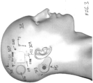
- FIG. 3 illustrates a pictorial view of a skull of a subject 311 with subcutaneous implants including the implantable device 200 of FIGs. 2A and 2B and a cochlear implant device 315.
- the surgical plane of the device 200 which is the XY plane shown, is approximately parallel to the skull at the position of implantation.
- This pictorial view illustrates the relatively small and straight, respective incisions (S1 307 and S2 309, blue straight lines) that are proximate and beside the implant location for insertion and/or removal of elements, in contrast with the more invasive and relatively larger arc incision (C 313, in blue) with a skin flap lift required for the cochlear implant.
- each S (for "straight") incision 307, 309 is circa 10mm long, whereas C 313 ("c-shaped" incision) is roughly 55mm long.
- an element can be insertably removable with respect to the housing via an incision through a skin of a subject, wherein a length of the incision is less than or equal to 20mm, 10mm, or 5mm, or wherein the length of the incision is in a range of 5mm to 20mm, and preferably 5mm to 15mm, or 7mm to 13mm.
- FIG. 4 is a flow diagram illustrating an embodiment procedure 400 for servicing an implantable device.
- the implantable device comprising a low-profile housing having a cavity defined in a side thereof and an element having a first portion adapted to be received in the housing cavity and a second portion adapted to protrude from the housing, insertably and removably accessing the element in a direction substantially parallel to a surgical plane of the implantable device.
- procedure 400 includes servicing additional elements of an embodiment device, as illustrated at 433.
- the cavity is considered to be a first cavity
- the side is considered to be a first side
- the element is considered to be a first element
- the incision is considered to be a first incision.
- the method further includes accessing at one or more respective second incisions proximate the implant location of the implantable device.
- the low-profile housing can have one or more respective second cavities defined in the first side or in one or more respective second sides thereof.
- the implantable device can include one or more second elements having respective first portions adapted to be received in the housing cavity.
- the accessing is particularly insertably and removably accessing the one or more second elements in one or more respective second directions substantially parallel to the surgical plane, as will be understood in relation to the description of other embodiments herein.
- the second portion includes at least one surface adapted for engagement with a surgical instrument for insertion and removal of the element with respect to the housing.
- the method may further be modified to utilize, employ, or operate upon any of the features of embodiments described above.
- first element when a first element is referred to as being “in”, “on” and/or “within” a second element, the first element can be positioned: within an internal space of the second element, within a portion of the second element (e.g. within a wall of the second element); positioned on an external and/or internal surface of the second element; and combinations of one or more of these.
- proximate when used to describe proximity of a first component or location to a second component or location, is to be taken to include one or more locations near to the second component or location, as well as locations in, on and/or within the second component or location.
- a component positioned proximate an anatomical site e.g. a target tissue location
- spatially relative terms such as “beneath”, “below”, “lower”, “above”, “upper” and the like may be used to describe an element and/or feature's relationship to another element(s) and/or feature(s) as, for example, illustrated in the figures. It will be further understood that the spatially relative terms are intended to encompass different orientations of the device in use and/or operation in addition to the orientation depicted in the figures. For example, if the device in a figure is turned over, elements described as “below” and/or “beneath” other elements or features would then be oriented “above” the other elements or features. The device can be otherwise oriented (e.g. rotated 90 degrees or at other orientations) and the spatially relative descriptors used herein interpreted accordingly.
- a functional element is to be taken to include one or more elements constructed and arranged to perform a function.
- a functional element can comprise a sensor and/or a transducer.
- a functional element is configured to deliver energy and/or otherwise treat tissue (e.g. a functional element configured as a treatment element).
- a functional element e.g. a functional element comprising a sensor
- a sensor or other functional element is configured to perform a diagnostic function (e.g.
- a functional element is configured to perform a therapeutic function (e.g. to deliver therapeutic energy and/or a therapeutic agent).
- a functional element comprises one or more elements constructed and arranged to perform a function selected from the group consisting of: deliver energy; extract energy (e.g. to cool a component); deliver a drug or other agent; manipulate a system component or subject tissue; record or otherwise sense a parameter such as a subject physiologic parameter or a system parameter; and combinations of one or more of these.
- a transducer where used herein is to be taken to include any component or combination of components that receives energy or any input, and produces an output.
- a transducer can include an electrode that receives electrical energy, and distributes the electrical energy to tissue (e.g. based on the size of the electrode).
- a transducer converts an electrical signal into any output, such as light (e.g. a transducer comprising a light emitting diode or light bulb), sound (e.g. a transducer comprising a piezo crystal configured to deliver ultrasound energy), pressure, heat energy, cryogenic energy, chemical energy; mechanical energy (e.g.
- a transducer comprising a motor or a solenoid), magnetic energy, and/or a different electrical signal (e.g. a Bluetooth or other wireless communication element).
- a transducer can convert a physical quantity (e.g. variations in a physical quantity) into an electrical signal.
- a transducer can include any component that delivers energy and/or an agent to tissue, such as a transducer configured to deliver one or more of: electrical energy to tissue (e.g. a transducer comprising one or more electrodes); light energy to tissue (e.g. a transducer comprising a laser, light emitting diode and/or optical component such as a lens or prism); mechanical energy to tissue (e.g. a transducer comprising a tissue manipulating element); sound energy to tissue (e.g. a transducer comprising a piezo crystal); chemical energy; electromagnetic energy; magnetic energy; and combinations of one or more of these.
- electrical energy to tissue e.g. a transducer comprising one or
- fluid can refer to a liquid, gas, gel, or any flowable material, such as a material which can be propelled through a lumen and/or opening.
Landscapes
- Health & Medical Sciences (AREA)
- Life Sciences & Earth Sciences (AREA)
- Engineering & Computer Science (AREA)
- General Health & Medical Sciences (AREA)
- Animal Behavior & Ethology (AREA)
- Veterinary Medicine (AREA)
- Public Health (AREA)
- Biomedical Technology (AREA)
- Nuclear Medicine, Radiotherapy & Molecular Imaging (AREA)
- Heart & Thoracic Surgery (AREA)
- Radiology & Medical Imaging (AREA)
- Otolaryngology (AREA)
- Surgery (AREA)
- Neurosurgery (AREA)
- Cardiology (AREA)
- Medical Informatics (AREA)
- Molecular Biology (AREA)
- Pathology (AREA)
- Oral & Maxillofacial Surgery (AREA)
- Signal Processing (AREA)
- Anesthesiology (AREA)
- Hematology (AREA)
- Pulmonology (AREA)
- Gastroenterology & Hepatology (AREA)
- Biophysics (AREA)
- Neurology (AREA)
- Acoustics & Sound (AREA)
- Physics & Mathematics (AREA)
- Prostheses (AREA)
Claims (12)
- Implantierbare Vorrichtung (100) umfassend:ein Niedrigprofilgehäuse (110) mit einer Breite (101) und einer Länge (103), die sich in X- und Y-Richtung einer chirurgischen XY-Ebene der implantierbaren Vorrichtung erstrecken, wobei die Breite und die Länge größer sind als eine Höhe (105) des Gehäuses, wobei das Gehäuse einen Hohlraum (150) aufweist, der in einer Seite davon definiert ist; undein implantierbares Element (120, 220a, 220b), das in Bezug auf den Hohlraum in der Seite des Gehäuses in einer Richtung im Wesentlichen parallel zu der chirurgischen XY-Ebene der implantierbaren Vorrichtung einführbar entfernbar ist, wobei das implantierbare Element einen ersten Abschnitt (124) aufweist, der angepasst ist, um in dem Gehäusehohlraum aufgenommen zu werden, und einen zweiten Abschnitt (128), der angepasst ist, um beim Einführen des Elements in den Gehäusehohlraum aus dem Gehäuse hervorzustehen, dadurch gekennzeichnet, dass der zweite Abschnitt ein distales Ende des implantierbaren Elements ist, das eine Arretierung (130) einschließt, die für Eingriff mit einem chirurgischen Instrument zum Einführen und Entfernen des implantierbaren Elements in Bezug auf das Gehäuse konfiguriert ist, wobei sich die Arretierung von einer Oberfläche des zweiten Abschnitts in den zweiten Abschnitt in einer Richtung senkrecht zu der chirurgischen XY-Ebene erstreckt.
- Vorrichtung nach Anspruch 1, wobei das implantierbare Element eines oder eine beliebige Kombination von: einem Magneten, einer Batterie, einem Sensor und einem elektronischen Modul einschließt.
- Vorrichtung nach Anspruch 1 oder 2, die ferner eine elektronische Schaltung (280) innerhalb des Gehäuses einschließt.
- Vorrichtung nach Anspruch 3, wobei das implantierbare Element dazu konfiguriert ist, eine elektrische Kopplung mit der elektronischen Schaltung aufzuweisen.
- Vorrichtung nach einem der Ansprüche 1 bis 4, wobei das implantierbare Element einen radio-opaken Marker einschließt.
- Vorrichtung nach einem der Ansprüche 1 bis 5, wobei das implantierbare Element einen RFID-Tag einschließt.
- Vorrichtung nach einem der Ansprüche 1 bis 6, wobei das implantierbare Element ein resorbierbares Material einschließt.
- Vorrichtung nach einem der Ansprüche 1 bis 7, wobei das implantierbare Element ein verbrauchbares Material einschließt.
- Vorrichtung nach einem der Ansprüche 1 bis 8, wobei das Gehäuse und das implantierbare Element aus biokompatiblen Materialien bestehen.
- Vorrichtung nach einem der Ansprüche 1 bis 9, wobei der erste Abschnitt angepasst ist, um reibschlüssig in den Hohlraum eingepasst zu sein.
- Vorrichtung nach einem der Ansprüche 1 bis 10, wobei der Hohlraum eine Hohlraumwand einschließt und der erste Abschnitt und die Hohlraumwand für Eingriff und Ausrichtung miteinander verkeilt sind.
- Vorrichtung nach einem der Ansprüche 1 bis 11, wobei der Hohlraum ein erster Hohlraum ist, die Seite eine erste Seite ist und das Element ein erstes Element ist, die Vorrichtung ferner einen oder mehrere zweite Hohlräume umfasst, die in der ersten Seite oder in einer oder mehreren jeweiligen zweiten Seiten des Niedrigprofilgehäuses definiert sind, die Vorrichtung ferner ein oder mehrere jeweilige zweite Elemente umfasst, die in Bezug auf das Gehäuse in einer oder mehreren jeweiligen zweiten Richtungen im Wesentlichen parallel zu der chirurgischen Ebene der implantierbaren Vorrichtung einführbar entfernbar sind, das eine oder die mehreren jeweiligen zweiten Elemente einen oder mehrere jeweilige erste Abschnitte aufweisen, die angepasst sind, um in dem Gehäusehohlraum aufgenommen zu werden.
Applications Claiming Priority (3)
| Application Number | Priority Date | Filing Date | Title |
|---|---|---|---|
| US202062964918P | 2020-01-23 | 2020-01-23 | |
| US202063131595P | 2020-12-29 | 2020-12-29 | |
| PCT/US2021/014520 WO2021150827A1 (en) | 2020-01-23 | 2021-01-22 | Implantable medical devices with insertably removable elements |
Publications (2)
| Publication Number | Publication Date |
|---|---|
| EP4093492A1 EP4093492A1 (de) | 2022-11-30 |
| EP4093492B1 true EP4093492B1 (de) | 2025-06-11 |
Family
ID=74626219
Family Applications (1)
| Application Number | Title | Priority Date | Filing Date |
|---|---|---|---|
| EP21705794.2A Active EP4093492B1 (de) | 2020-01-23 | 2021-01-22 | Implantierbare medizinprodukte mit einsetzbar abnehmbaren elementen |
Country Status (8)
| Country | Link |
|---|---|
| US (2) | US12329589B2 (de) |
| EP (1) | EP4093492B1 (de) |
| JP (1) | JP7603697B2 (de) |
| CN (1) | CN115666711B (de) |
| AU (1) | AU2021209663B2 (de) |
| CA (1) | CA3164584A1 (de) |
| ES (1) | ES3038018T3 (de) |
| WO (1) | WO2021150827A1 (de) |
Families Citing this family (1)
| Publication number | Priority date | Publication date | Assignee | Title |
|---|---|---|---|---|
| US12491043B2 (en) * | 2022-12-12 | 2025-12-09 | Aj1E Superior Solutions Llc | Holder for X-ray marker and associated method |
Family Cites Families (67)
| Publication number | Priority date | Publication date | Assignee | Title |
|---|---|---|---|---|
| US3951154A (en) * | 1974-04-30 | 1976-04-20 | Medtronic, Inc. | Lead connector for electro-medical device |
| US4141752A (en) * | 1977-07-21 | 1979-02-27 | Coratomic, Inc. | Organ-stimulating apparatus and insulating set screw for such apparatus |
| US4566464A (en) | 1981-07-27 | 1986-01-28 | Piccone Vincent A | Implantable epilepsy monitor apparatus |
| US5374279A (en) * | 1992-10-30 | 1994-12-20 | Medtronic, Inc. | Switchable connector block for implantable defibrillator |
| US5535097A (en) * | 1993-11-23 | 1996-07-09 | Medtronic, Inc. | Implantable medical device including a first enclosure portion having a feedthrough in a second interior surface |
| DE19544750A1 (de) * | 1995-11-30 | 1997-06-05 | Christoph Rehberg | Implantierbare Vorrichtung mit Innenelektrode zur Förderung des Gewebewachstums |
| WO1997036457A1 (en) | 1996-03-25 | 1997-10-02 | Lesinski S George | Attaching an implantable hearing aid microactuator |
| US6018682A (en) | 1998-04-30 | 2000-01-25 | Medtronic, Inc. | Implantable seizure warning system |
| US9113801B2 (en) | 1998-08-05 | 2015-08-25 | Cyberonics, Inc. | Methods and systems for continuous EEG monitoring |
| US6572655B1 (en) * | 1998-08-26 | 2003-06-03 | Lanny L. Johnson | Method for securing a prosthesis component to bone |
| WO2000025668A1 (en) | 1998-11-05 | 2000-05-11 | Medhkour Adel M | System and method for long-term recording of neural activity |
| SE523123C2 (sv) * | 2000-06-02 | 2004-03-30 | P & B Res Ab | Hörapparat som arbetar med principen benledning |
| WO2002007596A1 (en) | 2000-07-21 | 2002-01-31 | Medtronic, Inc. | Measurement and communication of body parameters |
| US7001333B2 (en) * | 2000-12-20 | 2006-02-21 | Hamel Ross J | Surgical retractor system |
| US6597953B2 (en) | 2001-02-20 | 2003-07-22 | Neuropace, Inc. | Furcated sensing and stimulation lead |
| US7787958B2 (en) * | 2001-04-13 | 2010-08-31 | Greatbatch Ltd. | RFID detection and identification system for implantable medical lead systems |
| US20030109903A1 (en) * | 2001-12-12 | 2003-06-12 | Epic Biosonics Inc. | Low profile subcutaneous enclosure |
| US20030144711A1 (en) | 2002-01-29 | 2003-07-31 | Neuropace, Inc. | Systems and methods for interacting with an implantable medical device |
| US20040193228A1 (en) * | 2003-03-31 | 2004-09-30 | Gerber Martin T. | Method, system and device for treating various disorders of the pelvic floor by electrical stimulation of the left and right pudendal nerves |
| US7218232B2 (en) * | 2003-07-11 | 2007-05-15 | Depuy Products, Inc. | Orthopaedic components with data storage element |
| CN101091114A (zh) | 2004-08-31 | 2007-12-19 | 生命扫描苏格兰有限公司 | 制造自动校准传感器的方法 |
| US8118741B2 (en) | 2004-12-20 | 2012-02-21 | Hypo-Safe A/X | Method and apparatus for prediction and warning of hypoglycaemic attack |
| US7840279B2 (en) * | 2005-02-11 | 2010-11-23 | Boston Scientific Neuromodulation Corporation | Implantable microstimulator having a separate battery unit and methods of use thereof |
| US7787945B2 (en) | 2006-03-08 | 2010-08-31 | Neuropace, Inc. | Implantable seizure monitor |
| US7676263B2 (en) | 2006-06-23 | 2010-03-09 | Neurovista Corporation | Minimally invasive system for selecting patient-specific therapy parameters |
| US7966077B2 (en) * | 2006-09-29 | 2011-06-21 | Cochlear Limited | Electrode assembly for a stimulating medical device |
| WO2008092133A2 (en) | 2007-01-25 | 2008-07-31 | Neurovista Corporation | Methods and systems for measuring a subject's susceptibility to a seizure |
| US8036736B2 (en) | 2007-03-21 | 2011-10-11 | Neuro Vista Corporation | Implantable systems and methods for identifying a contra-ictal condition in a subject |
| US8738139B2 (en) | 2007-08-01 | 2014-05-27 | Bruce Lanning | Wireless system for epilepsy monitoring and measurement |
| GB0800615D0 (en) | 2008-01-14 | 2008-02-20 | Hypo Safe As | Implantable electronic device |
| GB0804998D0 (en) * | 2008-03-18 | 2008-04-16 | Depuy Ireland Ltd | A cup component of an orthopaedic joint prosthesis |
| US8290593B2 (en) | 2008-10-31 | 2012-10-16 | Medtronic, Inc. | Implantable medical device including a plurality of lead connection assemblies |
| EP2445400A1 (de) | 2009-06-26 | 2012-05-02 | Widex A/S | Eeg-überwachungssystem und verfahren zur eeg-überwachung |
| BR112012003078A2 (pt) | 2009-08-17 | 2019-09-24 | Univ California | sistema de sensor externo interrogável para obter uma ou mais características biológicas de uma superfície ou região de tecido interno do corpo de um paciente, método para obter uma ou mais características biológicas de uma superfície ou regiaõ de tecido interno de um paciente, sistema de sensor transdérmico para obter uma ou mais características biológicas de uma regiaõ de tecido interno de paciente, método para obter uma ou mais características biológicas de uma região do tecido interno de um paciente e sistema de sensor interrogável para obter uma oumais características biológicas de uma regiaõ de tecido interno de um paciente |
| US9061134B2 (en) | 2009-09-23 | 2015-06-23 | Ripple Llc | Systems and methods for flexible electrodes |
| WO2011123150A2 (en) | 2009-10-20 | 2011-10-06 | The Regents Of The University Of Michigan | Distributed, minimally-invasive neural interface for wireless epidural recording |
| KR20120086324A (ko) | 2009-12-02 | 2012-08-02 | 비덱스 에이/에스 | Eeg 조립체를 지닌 사람에게 경고하는 방법 및 장치 |
| CA2788731C (en) | 2010-02-01 | 2016-06-21 | Widex A/S | A portable eeg monitor system with wireless communication |
| WO2012126003A1 (en) | 2011-03-17 | 2012-09-20 | Brown University | Implantable wireless neural device |
| US20130096366A1 (en) * | 2011-10-12 | 2013-04-18 | Wim Bervoets | Implantable medical device |
| US9526810B2 (en) | 2011-12-09 | 2016-12-27 | Sophono, Inc. | Systems, devices, components and methods for improved acoustic coupling between a bone conduction hearing device and a patient's head or skull |
| EP2870781B1 (de) | 2012-07-09 | 2019-05-01 | Med-El Elektromedizinische Geräte GmbH | Elektromagnetische knochenleitungshörvorrichtung |
| US10634181B2 (en) * | 2013-03-12 | 2020-04-28 | Case Western Reserve University | Asymmetrical-force connector system |
| US9516434B2 (en) | 2013-05-09 | 2016-12-06 | Cochlear Limited | Medical device coupling arrangement |
| AU2014268445B2 (en) * | 2013-05-22 | 2019-03-07 | Deep Brain Innovations LLC | Deep brain stimulator and method of use |
| WO2015130955A1 (en) | 2014-02-27 | 2015-09-03 | New York University | Minimally invasive subgaleal extra-cranial electroencephalography (eeg) monitoring device |
| BR112017006393B1 (pt) | 2014-10-03 | 2023-01-03 | Woodwelding Ag | Capacete de detecção e/ou de entrega para ser implantado em uma cabeça humana |
| TWI696448B (zh) | 2014-11-11 | 2020-06-21 | 芬蘭商腦部關懷公司 | 植入式電極裝置及其製造方法 |
| CN108367150B (zh) | 2014-11-26 | 2021-11-30 | Spr治疗股份有限公司 | 用于外周刺激的电刺激器 |
| DK3291730T3 (da) | 2015-05-04 | 2023-11-27 | T&W Eng A/S | Eeg-monitor med et hus individuelt tilpasset en person |
| FR3036623B1 (fr) | 2015-05-28 | 2017-05-19 | Commissariat Energie Atomique | Dispositif pour stimulation electrique et optique profonde du cerveau |
| US9872115B2 (en) | 2015-09-14 | 2018-01-16 | Cochlear Limited | Retention magnet system for medical device |
| WO2017101977A1 (en) | 2015-12-15 | 2017-06-22 | T&W Engineering A/S | An eeg monitor with an implantable part |
| US10129667B2 (en) | 2016-02-26 | 2018-11-13 | Cochlear Limited | Multi-pole magnetic coupling for bone conduction device |
| WO2017196477A1 (en) * | 2016-05-12 | 2017-11-16 | University Of Florida Research Foundation, Inc. | Subcutaneous defibrillation |
| WO2018032060A1 (en) | 2016-08-18 | 2018-02-22 | Durso Paul S | Wearable medical device and systems derived therefrom |
| EP3506979B1 (de) | 2016-09-01 | 2023-04-12 | Epi-Minder Pty Ltd | Elektrodenvorrichtung zur überwachung der gehirnaktivität bei einer person |
| US20180117331A1 (en) * | 2016-11-03 | 2018-05-03 | New York University | Minimally Invasive Subgaleal Extra-Cranial Electroencephalography EEG Monitoring Device |
| CA3070980C (en) | 2017-07-25 | 2023-10-31 | Seer Medical Pty Ltd | Methods and systems for forecasting seizures |
| US20200330749A1 (en) | 2017-12-28 | 2020-10-22 | Inner Cosmos Llc | Intracalvarial bci systems and methods for their making, implantation and use |
| JP7106914B2 (ja) | 2018-03-22 | 2022-07-27 | 住友ベークライト株式会社 | 留置型医療機器、留置型医療機器セット及び標識部セット |
| CN108606778B (zh) | 2018-04-16 | 2024-04-19 | 顾继炎 | 医疗装置、算法更新方法、医疗系统及外部监测装置 |
| EP3787735B1 (de) | 2018-05-01 | 2026-01-28 | Wyss Center for Bio and Neuro Engineering | Neuralschnittstellensystem |
| US12484829B2 (en) | 2018-08-27 | 2025-12-02 | Verily Life Sciences Llc | Thin-film high-density sensing array, sub-scalp implantation tool and implant method |
| CN113271856A (zh) | 2018-10-22 | 2021-08-17 | 爱思神经系统公司 | 优化用于短期半球脑监测的帽状腱膜下电极阵列的床边插入和记录功能的系统和方法 |
| WO2020160613A1 (en) | 2019-02-05 | 2020-08-13 | Commonwealth Scientific And Industrial Research Organisation | Brain activity monitoring |
| DE202019102592U1 (de) | 2019-05-08 | 2020-08-11 | Albert-Ludwigs-Universität Freiburg | Adaptive Tiefenhirnstimulation des superolateralen medialen Vorderhirnbündels |
-
2021
- 2021-01-22 ES ES21705794T patent/ES3038018T3/es active Active
- 2021-01-22 JP JP2022545008A patent/JP7603697B2/ja active Active
- 2021-01-22 EP EP21705794.2A patent/EP4093492B1/de active Active
- 2021-01-22 CN CN202180010294.4A patent/CN115666711B/zh active Active
- 2021-01-22 CA CA3164584A patent/CA3164584A1/en active Pending
- 2021-01-22 WO PCT/US2021/014520 patent/WO2021150827A1/en not_active Ceased
- 2021-01-22 US US17/155,249 patent/US12329589B2/en active Active
- 2021-01-22 AU AU2021209663A patent/AU2021209663B2/en active Active
-
2025
- 2025-05-13 US US19/206,706 patent/US20250387192A1/en active Pending
Also Published As
| Publication number | Publication date |
|---|---|
| EP4093492A1 (de) | 2022-11-30 |
| AU2021209663A1 (en) | 2022-08-11 |
| US20250387192A1 (en) | 2025-12-25 |
| US20210228310A1 (en) | 2021-07-29 |
| CN115666711B (zh) | 2026-04-07 |
| WO2021150827A1 (en) | 2021-07-29 |
| JP2023511962A (ja) | 2023-03-23 |
| CN115666711A (zh) | 2023-01-31 |
| AU2021209663B2 (en) | 2025-11-20 |
| JP7603697B2 (ja) | 2024-12-20 |
| ES3038018T3 (en) | 2025-10-08 |
| US12329589B2 (en) | 2025-06-17 |
| CA3164584A1 (en) | 2021-07-29 |
Similar Documents
| Publication | Publication Date | Title |
|---|---|---|
| US8792987B2 (en) | Satellite therapy delivery system for brain neuromodulation | |
| EP1624927B1 (de) | Implantierbare medizinische vorrichtung mit drahtmanagementeinrichtung | |
| US8412332B2 (en) | Miniature wireless system for deep brain stimulation | |
| US20040176817A1 (en) | Modular implantable medical device | |
| US20050003268A1 (en) | Battery housing configuration | |
| US10258801B2 (en) | Varying lead configuration implantable medical device | |
| WO2005039696A1 (en) | Intracranial neural interface system | |
| CN111886050A (zh) | 包括再充电和/或遥测线圈的植入式医疗设备结构 | |
| EP2421606B1 (de) | System aus einer box zur implantation in einen körperteil | |
| US20250387192A1 (en) | Implantable Medical Devices With Insertably Removable Elements | |
| EP2714191B1 (de) | Elektrische durchführung und elektrodenstruktur für implantierbare medizinische vorrichtung | |
| CN212940175U (zh) | 植入装置和具有其的视觉假体 | |
| EP2934289A1 (de) | Implantierbare medizinische vorrichtung zur minimal invasiven einführung | |
| EP2186541B1 (de) | Satellitensystem zur Therapiebereitstellung zur Neuromodulation im Gehirn | |
| WO2008110005A1 (en) | Implantable cardiac device |
Legal Events
| Date | Code | Title | Description |
|---|---|---|---|
| STAA | Information on the status of an ep patent application or granted ep patent |
Free format text: STATUS: UNKNOWN |
|
| STAA | Information on the status of an ep patent application or granted ep patent |
Free format text: STATUS: THE INTERNATIONAL PUBLICATION HAS BEEN MADE |
|
| PUAI | Public reference made under article 153(3) epc to a published international application that has entered the european phase |
Free format text: ORIGINAL CODE: 0009012 |
|
| STAA | Information on the status of an ep patent application or granted ep patent |
Free format text: STATUS: REQUEST FOR EXAMINATION WAS MADE |
|
| 17P | Request for examination filed |
Effective date: 20220808 |
|
| AK | Designated contracting states |
Kind code of ref document: A1 Designated state(s): AL AT BE BG CH CY CZ DE DK EE ES FI FR GB GR HR HU IE IS IT LI LT LU LV MC MK MT NL NO PL PT RO RS SE SI SK SM TR |
|
| DAV | Request for validation of the european patent (deleted) | ||
| DAX | Request for extension of the european patent (deleted) | ||
| STAA | Information on the status of an ep patent application or granted ep patent |
Free format text: STATUS: EXAMINATION IS IN PROGRESS |
|
| 17Q | First examination report despatched |
Effective date: 20230510 |
|
| GRAP | Despatch of communication of intention to grant a patent |
Free format text: ORIGINAL CODE: EPIDOSNIGR1 |
|
| STAA | Information on the status of an ep patent application or granted ep patent |
Free format text: STATUS: GRANT OF PATENT IS INTENDED |
|
| INTG | Intention to grant announced |
Effective date: 20250117 |
|
| GRAS | Grant fee paid |
Free format text: ORIGINAL CODE: EPIDOSNIGR3 |
|
| GRAA | (expected) grant |
Free format text: ORIGINAL CODE: 0009210 |
|
| STAA | Information on the status of an ep patent application or granted ep patent |
Free format text: STATUS: THE PATENT HAS BEEN GRANTED |
|
| AK | Designated contracting states |
Kind code of ref document: B1 Designated state(s): AL AT BE BG CH CY CZ DE DK EE ES FI FR GB GR HR HU IE IS IT LI LT LU LV MC MK MT NL NO PL PT RO RS SE SI SK SM TR |
|
| REG | Reference to a national code |
Ref country code: GB Ref legal event code: FG4D |
|
| REG | Reference to a national code |
Ref country code: CH Ref legal event code: EP |
|
| REG | Reference to a national code |
Ref country code: IE Ref legal event code: FG4D |
|
| REG | Reference to a national code |
Ref country code: DE Ref legal event code: R096 Ref document number: 602021032084 Country of ref document: DE |
|
| REG | Reference to a national code |
Ref country code: NL Ref legal event code: FP |
|
| REG | Reference to a national code |
Ref country code: ES Ref legal event code: FG2A Ref document number: 3038018 Country of ref document: ES Kind code of ref document: T3 Effective date: 20251008 |
|
| PG25 | Lapsed in a contracting state [announced via postgrant information from national office to epo] |
Ref country code: FI Free format text: LAPSE BECAUSE OF FAILURE TO SUBMIT A TRANSLATION OF THE DESCRIPTION OR TO PAY THE FEE WITHIN THE PRESCRIBED TIME-LIMIT Effective date: 20250611 |
|
| REG | Reference to a national code |
Ref country code: LT Ref legal event code: MG9D |
|
| PG25 | Lapsed in a contracting state [announced via postgrant information from national office to epo] |
Ref country code: NO Free format text: LAPSE BECAUSE OF FAILURE TO SUBMIT A TRANSLATION OF THE DESCRIPTION OR TO PAY THE FEE WITHIN THE PRESCRIBED TIME-LIMIT Effective date: 20250911 Ref country code: GR Free format text: LAPSE BECAUSE OF FAILURE TO SUBMIT A TRANSLATION OF THE DESCRIPTION OR TO PAY THE FEE WITHIN THE PRESCRIBED TIME-LIMIT Effective date: 20250912 |
|
| PG25 | Lapsed in a contracting state [announced via postgrant information from national office to epo] |
Ref country code: BG Free format text: LAPSE BECAUSE OF FAILURE TO SUBMIT A TRANSLATION OF THE DESCRIPTION OR TO PAY THE FEE WITHIN THE PRESCRIBED TIME-LIMIT Effective date: 20250611 |
|
| PG25 | Lapsed in a contracting state [announced via postgrant information from national office to epo] |
Ref country code: HR Free format text: LAPSE BECAUSE OF FAILURE TO SUBMIT A TRANSLATION OF THE DESCRIPTION OR TO PAY THE FEE WITHIN THE PRESCRIBED TIME-LIMIT Effective date: 20250611 |
|
| PG25 | Lapsed in a contracting state [announced via postgrant information from national office to epo] |
Ref country code: RS Free format text: LAPSE BECAUSE OF FAILURE TO SUBMIT A TRANSLATION OF THE DESCRIPTION OR TO PAY THE FEE WITHIN THE PRESCRIBED TIME-LIMIT Effective date: 20250911 |
|
| PG25 | Lapsed in a contracting state [announced via postgrant information from national office to epo] |
Ref country code: LV Free format text: LAPSE BECAUSE OF FAILURE TO SUBMIT A TRANSLATION OF THE DESCRIPTION OR TO PAY THE FEE WITHIN THE PRESCRIBED TIME-LIMIT Effective date: 20250611 |
|
| PG25 | Lapsed in a contracting state [announced via postgrant information from national office to epo] |
Ref country code: PT Free format text: LAPSE BECAUSE OF FAILURE TO SUBMIT A TRANSLATION OF THE DESCRIPTION OR TO PAY THE FEE WITHIN THE PRESCRIBED TIME-LIMIT Effective date: 20251013 |
|
| REG | Reference to a national code |
Ref country code: AT Ref legal event code: MK05 Ref document number: 1801896 Country of ref document: AT Kind code of ref document: T Effective date: 20250611 |
|
| PG25 | Lapsed in a contracting state [announced via postgrant information from national office to epo] |
Ref country code: IS Free format text: LAPSE BECAUSE OF FAILURE TO SUBMIT A TRANSLATION OF THE DESCRIPTION OR TO PAY THE FEE WITHIN THE PRESCRIBED TIME-LIMIT Effective date: 20251011 |
|
| PGFP | Annual fee paid to national office [announced via postgrant information from national office to epo] |
Ref country code: GB Payment date: 20251204 Year of fee payment: 6 |
|
| PG25 | Lapsed in a contracting state [announced via postgrant information from national office to epo] |
Ref country code: AT Free format text: LAPSE BECAUSE OF FAILURE TO SUBMIT A TRANSLATION OF THE DESCRIPTION OR TO PAY THE FEE WITHIN THE PRESCRIBED TIME-LIMIT Effective date: 20250611 Ref country code: SM Free format text: LAPSE BECAUSE OF FAILURE TO SUBMIT A TRANSLATION OF THE DESCRIPTION OR TO PAY THE FEE WITHIN THE PRESCRIBED TIME-LIMIT Effective date: 20250611 |
|
| PGFP | Annual fee paid to national office [announced via postgrant information from national office to epo] |
Ref country code: NL Payment date: 20251215 Year of fee payment: 6 Ref country code: FR Payment date: 20251128 Year of fee payment: 6 |
|
| PG25 | Lapsed in a contracting state [announced via postgrant information from national office to epo] |
Ref country code: CZ Free format text: LAPSE BECAUSE OF FAILURE TO SUBMIT A TRANSLATION OF THE DESCRIPTION OR TO PAY THE FEE WITHIN THE PRESCRIBED TIME-LIMIT Effective date: 20250611 |
|
| PG25 | Lapsed in a contracting state [announced via postgrant information from national office to epo] |
Ref country code: PL Free format text: LAPSE BECAUSE OF FAILURE TO SUBMIT A TRANSLATION OF THE DESCRIPTION OR TO PAY THE FEE WITHIN THE PRESCRIBED TIME-LIMIT Effective date: 20250611 |
|
| PG25 | Lapsed in a contracting state [announced via postgrant information from national office to epo] |
Ref country code: EE Free format text: LAPSE BECAUSE OF FAILURE TO SUBMIT A TRANSLATION OF THE DESCRIPTION OR TO PAY THE FEE WITHIN THE PRESCRIBED TIME-LIMIT Effective date: 20250611 |
|
| PG25 | Lapsed in a contracting state [announced via postgrant information from national office to epo] |
Ref country code: SK Free format text: LAPSE BECAUSE OF FAILURE TO SUBMIT A TRANSLATION OF THE DESCRIPTION OR TO PAY THE FEE WITHIN THE PRESCRIBED TIME-LIMIT Effective date: 20250611 |
|
| REG | Reference to a national code |
Ref country code: CH Ref legal event code: U11 Free format text: ST27 STATUS EVENT CODE: U-0-0-U10-U11 (AS PROVIDED BY THE NATIONAL OFFICE) Effective date: 20260201 |
|
| REG | Reference to a national code |
Ref country code: DE Ref legal event code: R097 Ref document number: 602021032084 Country of ref document: DE |
|
| PGFP | Annual fee paid to national office [announced via postgrant information from national office to epo] |
Ref country code: ES Payment date: 20260209 Year of fee payment: 6 |
|
| PG25 | Lapsed in a contracting state [announced via postgrant information from national office to epo] |
Ref country code: DK Free format text: LAPSE BECAUSE OF FAILURE TO SUBMIT A TRANSLATION OF THE DESCRIPTION OR TO PAY THE FEE WITHIN THE PRESCRIBED TIME-LIMIT Effective date: 20250611 |
|
| PGFP | Annual fee paid to national office [announced via postgrant information from national office to epo] |
Ref country code: DE Payment date: 20251126 Year of fee payment: 6 |
|
| PGFP | Annual fee paid to national office [announced via postgrant information from national office to epo] |
Ref country code: IT Payment date: 20251219 Year of fee payment: 6 |
|
| PLBE | No opposition filed within time limit |
Free format text: ORIGINAL CODE: 0009261 |
|
| STAA | Information on the status of an ep patent application or granted ep patent |
Free format text: STATUS: NO OPPOSITION FILED WITHIN TIME LIMIT |
|
| PGFP | Annual fee paid to national office [announced via postgrant information from national office to epo] |
Ref country code: CH Payment date: 20260201 Year of fee payment: 6 |
|
| REG | Reference to a national code |
Ref country code: CH Ref legal event code: L10 Free format text: ST27 STATUS EVENT CODE: U-0-0-L10-L00 (AS PROVIDED BY THE NATIONAL OFFICE) Effective date: 20260423 |