EP4093669B1 - Systèmes d'aéronef et connecteurs électriques - Google Patents
Systèmes d'aéronef et connecteurs électriques Download PDFInfo
- Publication number
- EP4093669B1 EP4093669B1 EP21707311.3A EP21707311A EP4093669B1 EP 4093669 B1 EP4093669 B1 EP 4093669B1 EP 21707311 A EP21707311 A EP 21707311A EP 4093669 B1 EP4093669 B1 EP 4093669B1
- Authority
- EP
- European Patent Office
- Prior art keywords
- connector body
- aircraft system
- cable harness
- aircraft
- connector
- Prior art date
- Legal status (The legal status is an assumption and is not a legal conclusion. Google has not performed a legal analysis and makes no representation as to the accuracy of the status listed.)
- Active
Links
Images


Classifications
-
- B—PERFORMING OPERATIONS; TRANSPORTING
- B64—AIRCRAFT; AVIATION; COSMONAUTICS
- B64C—AEROPLANES; HELICOPTERS
- B64C9/00—Adjustable control surfaces or members, e.g. rudders
- B64C9/14—Adjustable control surfaces or members, e.g. rudders forming slots
- B64C9/22—Adjustable control surfaces or members, e.g. rudders forming slots at the front of the wing
-
- B—PERFORMING OPERATIONS; TRANSPORTING
- B64—AIRCRAFT; AVIATION; COSMONAUTICS
- B64C—AEROPLANES; HELICOPTERS
- B64C9/00—Adjustable control surfaces or members, e.g. rudders
- B64C9/14—Adjustable control surfaces or members, e.g. rudders forming slots
-
- H—ELECTRICITY
- H02—GENERATION; CONVERSION OR DISTRIBUTION OF ELECTRIC POWER
- H02G—INSTALLATION OF ELECTRIC CABLES OR LINES, OR OF COMBINED OPTICAL AND ELECTRIC CABLES OR LINES
- H02G11/00—Arrangements of electric cables or lines between relatively-movable parts
-
- B—PERFORMING OPERATIONS; TRANSPORTING
- B64—AIRCRAFT; AVIATION; COSMONAUTICS
- B64D—EQUIPMENT FOR FITTING IN OR TO AIRCRAFT; FLIGHT SUITS; PARACHUTES; ARRANGEMENT OR MOUNTING OF POWER PLANTS OR PROPULSION TRANSMISSIONS IN AIRCRAFT
- B64D15/00—De-icing or preventing icing on exterior surfaces of aircraft
- B64D15/12—De-icing or preventing icing on exterior surfaces of aircraft by electric heating
Definitions
- the present invention relates to aircraft systems and electrical connectors for aircraft systems.
- Aircraft systems may comprise many component parts, and at least some of those component parts may be movable relative to one another. It may sometimes be desirable to transfer electrical power between two such components, which may introduce challenges that can be exacerbated depending on the type of aircraft system and the type of relative motion required.
- US 2010/0130065 A1 and EP 2397404 A2 relate to aircraft systems comprising a telescopic strut arranged to extend and retract as one component moves relative to the other.
- the strut is pivotably coupled to the components at its end portions.
- electrical power is provided from one component to another by means of a telescopic conductor inside the strut.
- electrical power is provided by a helical cable inside the strut.
- US 2010/0193642 A1 discloses an aircraft wing comprising a wing fixed central body, and a leading edge mobile slat designed to be moved in rotation relative to the fixed central body along a circular trajectory inscribed on a sphere with centre C.
- the wing also comprises a cable carrier chain comprising links articulated to each other through articulation axes that converge towards a single point, the chain being connected at its two ends to the fixed central body and to the mobile slat.
- the single point is the centre C of the sphere, located on a rotation axis of the leading edge mobile slat relative to the wing fixed body.
- a first aspect of the present invention provides an aircraft system comprising a first structure, a second structure coupled to the first structure and movable between first and second positions relative to the first structure, and an electrical connector for providing an electrical connection running between respective components housed within the first and second structures, the electrical connector comprising a cable harness housed within the first structure, and a connector body coupled to an end of the cable harness, the connector body extending through an aperture formed in the first structure, and the connector body coupled to the second structure such that movement of the second structure between the first and second positions relative to the first structure causes the connector body to move through the aperture, wherein the connector body is fixedly attached to the second structure, and the system further comprises a guide within the first structure arranged to enable the cable harness to sweep in a predetermined range of motion as the second structure moves between the first and second positions.
- the guide defines a track which enables motion of the cable harness, with respect to the track, in a direction substantially corresponding to the direction of extent of the connector body in use.
- the connector body is coupled to an end of the cable harness, the connector body extends through an aperture formed in the first structure, and the connector body is coupled to the second structure such that movement of the second structure between the first and second positions relative to the first structure causes the connector body to move through the aperture.
- this may enable the connector body to extend between the first and second structures whilst not requiring the cable harness to extend in a similar manner.
- This may allow the connector body to be designed specifically to cope with the requirements of being located between the first and second structure, whilst also allowing for a conventional cable harness to be used.
- the connector body may be coupled to the harness such that the connector body extends substantially orthogonally relative to a principal direction of extent of the cable harness within the first structure.
- the aircraft system may be configured so that the connector body follows a pre-defined path relative to the first structure when the second structure is moved between the first and second positions.
- the connector body may comprise a rigid material, which may result in the connector body following a pre-defined path relative to the first structure when the second structure is moved between the first and second positions in use. This may provide a rigid component located between the first and second structures, which may allow for reliable performance and for the connector body to be located in a wide variety of environments.
- the connector body may be exposed to airflow when the second structure is in the second position.
- the connector body may comprise a rigid outer shell. This may, for example, enable the connector body to be exposed to an airflow when between the first and second components in use. This may reduce the risk in path deviations negatively impacting an electrical connection provided by the electrical connector.
- the connector body may comprise a composite material.
- the connector body may comprise an outer shell, and the outer shell may be a monolithic structure, i.e. a singular component. This may reduce the number of parts of the connector body, which may reduce cost.
- the connector body may comprise an internal holding member for holding an electrical power cable. This may be beneficial as the internal holding member may be used to retain a fixed position of an electrical power cable within the connector body as the connector body moves relative to the first structure in use. This may provide a relatively stable arrangement, which may be particularly useful where the connector body is exposed to airflow in use.
- the internal holding member may comprise a plurality of holding channels, with electrically insulative material located between the holding channels. This may enable the cables to be electrically isolated from one another within the connector body.
- the outer shell of the connector body may be overmoulded onto the internal holding member.
- At least a portion of the connector body may be exposed between the first structure and the second structure when the second structure is in the second position. For example, at least 50% of a length of the connector body may be exposed between the first structure and the second structure when the second structure is in the second position. At least a portion of the connector body may extend through the aperture when the second structure is in the first position and when the second structure is in the second position. Thus, the connector body may fill at least a portion of the aperture both when the second structure is in the first position and when the second structure is in the second position.
- the aircraft system may comprise a seal between the connector body and the perimeter of the aperture. This may prevent ingress of debris into the interior of the first structure via the aperture in use.
- the second structure may be spaced further from the first structure when at the second position compared to the first position
- the connector body may comprise an aerodynamic shape that is exposed when the second structure is in the second position.
- an outer surface of the connector body may comprise an aerodynamic shape. This may enable the connector body to be used in a scenario where air flows between the first and second structures in use.
- the aerodynamic shape may comprise a curved shape, for example an aerofoil shape.
- the connector body is fixedly coupled to the second structure.
- a first end of the connector body may be fixedly coupled to the second structure.
- movement of the second structure relative to the first structure may cause movement of the connector body relative to the first structure in use.
- a first end of the connector body may be fixedly coupled to the second structure and a second end of the connector body may be slidably received within the aperture. This may reduce the number of fixings required for the electrical connector, thereby reducing component count and cost.
- the connector body may be slidable through the aperture.
- a first end of the connector body may be fixedly coupled to the second structure and a second end of the connector body may be supported by a perimeter of the aperture, for example supported by a perimeter of the aperture when the second structure is in both its first and second positions relative to the first structure.
- the aircraft comprises a guide for restricting motion of the cable harness in at least one plane of motion during movement of the second structure between the first and second positions.
- This may be beneficial as the cable harness may have a relatively flexible nature when compared to the connector body.
- motion of the cable harness may be restricted to ensure that the cable harness does not interfere with further components of the aircraft system in use.
- the cable harness is substantially contained within the first structure, and the guide restricts motion of the cable harness within the first structure.
- the guide may allow motion in each of the planes of motion, whilst restricting motion in at least one plane.
- the aircraft system may comprise a guide for restricting motion of the cable harness in at least two planes of motion during movement of the second structure between the first and second positions.
- the guide comprises track housed within the first structure.
- the guide allows motion of the cable harness that corresponds to motion of the second structure between the first and second positions. Specifically, the guide allows the cable harness to sweep in a direction substantially corresponding to a direction of extent of the connector body in use.
- the cable harness may be fixed relative to the first structure at a fixation point within the first structure, the fixation point being remote from the end of the cable harness which is coupled to the connector body. This may support the cable harness at the fixation point, which may prevent the cable harness from flexing to an unacceptable degree within the first structure.
- the fixation point may allow substantially no motion of the cable harness in at least two planes.
- the fixation point may comprise a loop having a cross-sectional shape and size substantially corresponding to a cross-sectional shape and size of the cable harness.
- a section of the cable harness between the fixation point and the connector body may held by the guide, for example such that a section of the cable harness between the fixation point and the connector body is allowed to sweep within the first structure when the second structure is moved from the first position to the second position, and vice versa.
- the connector body may be curved, and a curvature of the connector body may correspond to a range of motion of the second structure as it moves between the first and second positions. This may be beneficial as it may allow for a smooth motion of both the connector body and the second structure as the second structure is moved between the first and second positions.
- a curvature of the connector body may correspond to a curvature of a track which defines motion of the second structure relative to the first structure.
- the aircraft system may comprise a power cable and/or a signal cable that runs through the harness and/or the connector body.
- the aircraft system may comprise a HVDC power cable and/or a data signal cable that run through the harness and/or the connector body.
- the electrical connector may enable transfer of one or both of power and signals between the first and second structures in use.
- the connector body may comprise a connection portion, for example at an end of the connector body remote from the coupling to the cable harness.
- the connector portion may be housed within the second structure, for example such that a further cable harness within the second structure does not need to extend out of the second structure.
- the connector portion may comprise a plurality of different connection types, for example a HVDC connector portion and a signal connector portion.
- the first structure may comprise a fixed wing structure
- the second structure may comprise a flight control surface coupled to the fixed wing structure.
- the first and second positions of the second structure may comprise retracted and deployed positions of the flight control surface.
- the flight control surface may be movable between retracted and deployed positions relative to the fixed wing structure.
- the connector body may extend between the fixed wing structure and the flight control surface when the flight control surface is in a deployed position.
- the second structure may comprise a heating device, and the electrical connector may provide an electrical connection from the first structure to the heating device.
- the first structure comprises a fixed wing structure
- the second structure comprises a flight control surface coupled to the fixed wing structure.
- the heater may be used to prevent build-up of ice on the flight control surface during operation of an aircraft in use.
- a second aspect of the present invention provides an aircraft comprising an aircraft system of the first aspect.
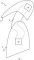
- An aircraft system is shown schematically in Figures 1 to 4 , and takes the form of an aircraft wing system.
- the aircraft wing system 10 comprises a fixed wing structure 12, and a flight control surface 14 movable between a first retracted position relative to the fixed wing structure 12, and a second deployed position relative to the fixed wing structure 12.
- the flight control surface 14 is shown in the retracted and deployed positions in Figures 1 and 2 respectively, and the aircraft wing system 10 is shown with the flight control surface 14 removed for clarity in Figures 3 and 4 .
- the flight control surface 14 may comprise any of an aileron, a flap, a slat, an elevator, a rudder or the like.
- the aircraft system 10 comprises a first electrical component 16 housed within the fixed wing structure 12, a second electrical component 18 housed within the flight control surface 14, and an electrical connector 20 for providing an electrical connection between the first 16 and second 18 components.
- the first 16 and second 18 electrical components are taken to be a power source 16 and a heater 18. This may particularly be the case where, for example, a heater is required in the flight control surface 14 to prevent the build-up of ice in use.
- the power source 16 itself is depicted here as being within the fixed wing structure 12, it will be appreciated that in practice the power source 16 may be located within a further component of an aircraft, for example the fuselage of an aircraft, but that the connectors from the power source 16 may still extend through the fixed wing structure 12, and that the electrical connector 20 may still be utilised for such an example.
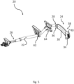
- the electrical connector 20 is shown in isolation in Figure 5 , and comprises a cable harness 22 and a connector body 24.
- the cable harness 22 is a combined high voltage DC (HVDC) and signal harness, and carries both HVDC and signal cabling from the power source 16 to the connector body 24.
- a first end 26 of the cable harness 22 is coupled to the power source 16 by appropriate cabling, and a second end 28 of the cable harness 22 is coupled to the connector body 24.
- the cable harness 22 may be a conventional cable harness chosen appropriately for the aircraft wing system 10.
- the connector body 24 comprises a composite shell 30, a structural foam core 32, and a connection portion 34.
- the composite shell 30 is generally elongate in form, and is curved along its length between a first end 36 coupled to the second end 28 of the cable harness 2, and a second end 38 in the region of the connection portion 34.
- the curvature of the composite shell 30 substantially matches a curved range of motion between the flight control surface 14 and the fixed wing structure 12 as the flight control surface 14 moves between its retracted and deployed positions relative to the fixed wing structure 12.
- the composite shell 30 is rigid such that deflections due to aerodynamic loading and vibration may be reduced, and is a monolithic component.
- the second end 38 of the composite shell 30 comprises a collar 40, with the collar 40 comprising a plurality of coupling points for coupling the composite shell 30 to an interior surface 44 of the flight control surface 14.
- the composite shell 30 extends through an aperture (not shown) in the flight control surface 14, such that the collar 40 is fixedly coupled to an interior surface 44 of the flight control surface 14 and the connection portion 34 is housed within the interior of the flight control surface 14.
- the composite shell 30, and hence the connector body 24 may be supported at the second end 38 by the flight control surface 14.
- a cross-sectional shape of the composite shell 30 between the first 36 and second 38 ends is an aerodynamic shape, for example an aerofoil shape.
- This aerodynamic shape of the composite shell 30 is exposed between the fixed wing structure 12 and the flight control surface 14 when the flight control surface 14 is in its deployed position relative to the fixed wing structure 12, and hence may provide aerodynamic benefits.
- the cross-sectional shape of the composite shell 30 is also such that its height is greater than its width. This may minimise the extent to which the connector body 24 extends across the span of the fixed wing structure 12 and the flight control surface 14, which may save space for other components.
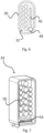
- the structural foam core 32 is provided internally of the composite shell 30, as can be seen from Figure 6 , and defines an internal holding member.
- the structural foam core 32 comprises a plurality of channels 46, with each channel configured to receive a HVDC cable from the cable harness 22, and a plastic conduit 48 configured to receive signal cables from the cable harness 22.
- the structural foam core 32 may be any suitable structural foam core, for example a closed cell foam core.
- the structural foam core 32 holds HVDC and signal cables within the connector body 24 in use.
- An alternative internal holding member not shown here may take the form of a series of spacers or inserts housed within the composite shell 30. This may allow for the composite shell to be formed from more than one piece.
- connection portion 34 is disposed at the second end 38 of the composite shell 30, and extends from the composite shell 30 such that the connection portion is located within the interior of the flight control surface 14 in use.
- the connection portion 34 can be seen in more detail in Figure 7 .
- the connection portion 34 interfaces with HVDC cables held within the structural foam core 32, and comprises a plurality of output HVDC contacts 50 which interact with corresponding HVDC electrical contacts (not shown) of the heater 18.
- the connection portion 34 also interfaces with signal cables held within the structural foam core 32, and comprises a plurality of output signal contacts 52 which interact with corresponding signal contacts (not shown) of the heater 18.
- the output HVDC contacts 50 and the output signal contacts 52 are located in different sections of the connection portion 34, with a physical barrier 54 between the output HVDC contacts 50 and the output signal contacts 52. This may provide appropriate electrical segregation at the connector level.
- the connector body 24 extends through an aperture 56 formed in an outer surface 58 of the fixed wing structure 12.
- a seal 60 is provided between the composite shell 30 and the aperture 56, and is indicated by hashed lines in Figure 4 .
- the interface between the composite shell 30 and the aperture 56 may itself define the seal 60, but in other instances, as shown in Figure 4 , the seal 60 comprises a resilient material located between the composite shell 30 and the perimeter of the aperture 56.
- the size of the aperture 56 has been exaggerated for the sake of clarity, and that in practice the aperture 56 may have a size which closely matches an outer perimeter of the composite shell 30
- the connector body 24 is not fixed to the fixed wing structure 12, such that the connector body 24 is slidable within the aperture 56.
- the second end 38 of the composite shell 30 is fixedly attached to the flight control surface 14.
- the connector body 24 is slidable through the aperture 56 between its own retracted position relative to the fixed wing structure 12 and its own deployed position relative to the fixed wing structure 12.
- This motion is illustrated schematically in Figures 1-4 .
- the connector body 24 extends through the aperture 56.
- the cable harness 22 is not required to be exposed between the fixed wing structure 12 and the flight control surface 14 in use, which may remove design constraints for the cable harness 22.
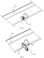
- motion of the cable harness 22 within the fixed wing structure 12 is limited by a fixation structure 62 and a guide 64 with the fixed wing structure 12 indicated by dotted lines.
- the fixation structure 62 takes the form of an annular loop fixed within the fixed wing structure 12 by a bracket.
- the inner diameter of the fixation structure 62 is chosen to correspond substantially to an outer diameter of the cable harness 22, and the cable harness 22 is held within the fixation structure 62 such that motion of the cable harness 22, particularly in vertical and front-back directions (i.e. not necessarily in the span direction) of the fixed wing structure 12 is limited.
- the fixation structure may ensure that the cable harness 22 does not extend within the fixed wing structure 12 unsupported to too great an extent, and hence may prevent potential clashes with further components housed within the fixed wing structure 12 in use.
- the guide 64 is located between the fixation structure 62 and the second end 28 of the cable harness 22 that is attached to the connector body 24.
- the guide 64 also takes the form of a full loop fixed within the fixed wing structure 12, but unlike the fixation structure 62, the guide 64 defines a track which enables motion of the cable harness 22 in both a front-back direction, for example a direction between a frontward facing surface and a rearward facing surface of the fixed wing structure 12 when installed on an aircraft 100, and a vertical direction (i.e. not necessarily in the span direction) of the fixed wing structure 12.
- the guide 64 enables the cable harness 22 to sweep, to a limited extent, within the fixed wing structure as the flight control surface 14 and the connector body 24 move between their retracted and deployed positions.
- This sweep of the cable harness 22 can be seen schematically in Figures 8 and 9 .
- This may help to encourage a smooth transition of the cable harness 22 when the flight control surface 14 and the connector body 24 move between their retracted and deployed positions, and may prevent excessive harness bending in use, which may be particularly problematic with HVDC cables that have a relatively low flexibility.
- the degree of motion afforded by the guide 64 may match movement of the flight control surface 14 relative to the fixed wing structure 22 for example with the shape of the guide 64 matching the shape of motion of the flight control surface 14 relative to the fixed wing structure 22. This may minimise vertical bending of the cable harness 22 during motion of the flight control surface 14 in use.
- the guide 64 may ensure that the cable harness 22 does not extend within the fixed wing structure 12 unsupported to too great an extent, and hence may prevent potential clashes with further components housed within the fixed wing structure 12 in use.
- a low-friction bushing (not shown) may be provided between the cable harness 22 and the guide 64.
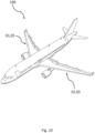
- FIG. 10 An aircraft 100 comprising the aircraft wing system 10 and electrical connector 20 is illustrated schematically in Figure 10 .
- an electrical connector 20 providing an electrical connection between respective components housed within a fixed wing structure 12 and a flight control surface 14, it will be recognised that the electrical connector 20 may also find utility for any appropriate aircraft system where there are fixed and movable structures.
- the composite shell 30 is described above as extending through an aperture in the flight control surface 14, in other examples the composite shell 30 may be attached to an exterior surface of the flight control surface 14 whilst the connection portion 34 extends through an aperture in the flight control surface. Furthermore, the composite shell 30 may not necessarily be curved, and may instead be straight in form. Whilst described herein as a heater, the second electrical component 18 in other examples may comprise lights, or sensors such as pressure sensors. It will further be appreciated that the electrical connector 20 may only carry power, or may only carry signals, as appropriate.
Landscapes
- Engineering & Computer Science (AREA)
- Aviation & Aerospace Engineering (AREA)
- Connector Housings Or Holding Contact Members (AREA)
Claims (17)
- Système d'aéronef (10) comprenant une première structure (12), une seconde structure (14) couplée à la première structure et mobile entre des première et seconde positions par rapport à la première structure, et un connecteur électrique (20) pour fournir une connexion électrique entre des composants (16, 18) respectifs logés dans les première et seconde structures (12, 14), le connecteur électrique (20) comprenant un faisceau de câbles (22) logé à l'intérieur de la première structure (12), et un corps de connecteur (24) couplé à une extrémité du faisceau de câbles (22), le corps de connecteur (24) s'étendant à travers une ouverture (56) formée dans la première structure (12), et le corps de connecteur (24) étant couplé à la seconde structure (14) de telle sorte que le mouvement de la seconde structure entre les première et seconde positions par rapport à la première structure amène le corps de connecteur (24) à se déplacer à travers l'ouverture (56),
dans lequel :le corps de connecteur (24) est fixé de manière fixe à la seconde structure (14) ; etle système comprend en outre un guide (64) à l'intérieur de la première structure (12) agencé pour permettre au faisceau de câbles (22) de balayer dans une plage de mouvement prédéterminée lorsque la seconde structure (14) se déplace entre les première et seconde positions,caractérisé en ce que :
le guide définit une piste qui permet un mouvement du faisceau de câbles, par rapport à la piste, dans une direction correspondant sensiblement à la direction d'extension du corps de connecteur en utilisation. - Système d'aéronef selon la revendication 1, dans lequel le système d'aéronef est configuré de sorte que le corps de connecteur (24) suit un trajet prédéfini par rapport à la première structure (12) lorsque la seconde structure (14) est déplacée entre les première et seconde positions.
- Système d'aéronef selon la revendication 1 ou la revendication 2, dans lequel le corps de connecteur (24) comprend une enveloppe externe (30) qui est une structure monolithique.
- Système d'aéronef selon l'une quelconque des revendications précédentes, dans lequel le corps de connecteur (24) comprend une enveloppe externe rigide (30).
- Système d'aéronef selon l'une quelconque des revendications précédentes, dans lequel le corps de connecteur (24) comprend un élément de support interne pour supporter un câble d'alimentation électrique.
- Système d'aéronef selon l'une quelconque des revendications précédentes, dans lequel au moins une partie du corps de connecteur (24) est exposée entre la première structure (12) et la seconde structure (14) lorsque la seconde structure (14) est dans la seconde position.
- Système d'aéronef selon l'une quelconque des revendications précédentes, dans lequel le corps de connecteur (24) comprend une forme aérodynamique qui est exposée lorsque la seconde structure (14) est dans la seconde position.
- Système d'aéronef selon l'une quelconque des revendications précédentes, dans lequel le faisceau de câbles (22) est fixé par rapport à la première structure (12) au niveau d'un point de fixation (62) à l'intérieur de la première structure (12), le point de fixation (62) étant distant de l'extrémité du faisceau de câbles (22) qui est couplé au corps de connecteur (24).
- Système d'aéronef selon l'une quelconque des revendications précédentes, dans lequel le corps de connecteur (24) est courbé, et une courbure du corps de connecteur correspond à une plage de mouvement de la seconde structure (14) lorsqu'elle se déplace entre les première et seconde positions.
- Système d'aéronef selon l'une quelconque des revendications précédentes, dans lequel le corps de connecteur (24) peut coulisser à travers l'ouverture (56).
- Système d'aéronef selon l'une quelconque des revendications précédentes, dans lequel le système d'aéronef comprend un joint (60) entre le corps de connecteur (24) et la première structure (12).
- Système d'aéronef selon l'une quelconque des revendications précédentes, dans lequel le corps de connecteur (24) a une hauteur et une largeur, dans lequel la hauteur est supérieure à la largeur, avec la hauteur et la largeur étant généralement perpendiculaires à un trajet le long duquel le corps de connecteur (24) se déplace pendant un mouvement à travers l'ouverture (56).
- Système d'aéronef selon l'une quelconque des revendications précédentes, dans lequel le système d'aéronef (10) comprend un câble d'alimentation et un câble de données qui s'étendent à travers le faisceau de câbles (22) et le corps de connecteur (24).
- Système d'aéronef selon l'une quelconque des revendications précédentes, dans lequel le corps de connecteur (24) comprend une partie de connexion (34) comprenant une pluralité de types de connexion (50, 52) différents.
- Système d'aéronef selon l'une quelconque des revendications précédentes, dans lequel la première structure comprend une structure d'aile fixe (12), la seconde structure comprend une surface de commande de vol (14) couplée à la structure d'aile fixe, et les première et seconde positions de la seconde structure sont des positions rétractée et déployée de la surface de commande de vol (14).
- Système d'aéronef selon l'une quelconque des revendications précédentes, dans lequel la seconde structure comprend un dispositif de chauffage (18), et le connecteur électrique (20) fournit une connexion électrique de la première structure (12) au dispositif de chauffage (18).
- Aéronef comprenant un système d'aéronef selon l'une quelconque des revendications 1 à 16.
Applications Claiming Priority (2)
| Application Number | Priority Date | Filing Date | Title |
|---|---|---|---|
| GB2003541.6A GB2593446A (en) | 2020-03-11 | 2020-03-11 | Aircraft systems and electrical connectors |
| PCT/EP2021/055046 WO2021180504A1 (fr) | 2020-03-11 | 2021-03-01 | Systèmes d'aéronef et connecteurs électriques |
Publications (2)
| Publication Number | Publication Date |
|---|---|
| EP4093669A1 EP4093669A1 (fr) | 2022-11-30 |
| EP4093669B1 true EP4093669B1 (fr) | 2024-09-25 |
Family
ID=70453536
Family Applications (1)
| Application Number | Title | Priority Date | Filing Date |
|---|---|---|---|
| EP21707311.3A Active EP4093669B1 (fr) | 2020-03-11 | 2021-03-01 | Systèmes d'aéronef et connecteurs électriques |
Country Status (4)
| Country | Link |
|---|---|
| US (1) | US12348014B2 (fr) |
| EP (1) | EP4093669B1 (fr) |
| GB (1) | GB2593446A (fr) |
| WO (1) | WO2021180504A1 (fr) |
Families Citing this family (4)
| Publication number | Priority date | Publication date | Assignee | Title |
|---|---|---|---|---|
| CN114421375B (zh) * | 2022-01-20 | 2023-09-05 | 中国商用飞机有限责任公司 | 用于飞机固定前缘和缝翼的线缆引导装置 |
| US12176697B2 (en) * | 2023-03-24 | 2024-12-24 | Archer Aviation Inc. | Systems and methods for routing electrical wiring through an aircraft structure |
| FR3162939A1 (fr) * | 2024-05-28 | 2025-12-05 | Safran Aircraft Engines | Dispositif de maintien d'un câble ou d’un faisceau de câbles d’alimentation électrique d’une pale d’un moteur d’aéronef |
| FR3162732A1 (fr) * | 2024-05-28 | 2025-12-05 | Safran Aircraft Engines | Dispositif de montage d'un câble dans un ensemble rotatif d'un système propulsif d'aéronef |
Family Cites Families (8)
| Publication number | Priority date | Publication date | Assignee | Title |
|---|---|---|---|---|
| US4615499A (en) * | 1983-08-12 | 1986-10-07 | The Boeing Company | Wing slat anti-ice air duct system |
| CA2515276A1 (fr) * | 2004-08-23 | 2006-02-23 | Goodrich Corporation | Aile d'aeronef |
| GB2417937B (en) * | 2004-09-10 | 2009-08-12 | Ultra Electronics Ltd | An aircraft wing coupling arrangement |
| GB0709128D0 (en) * | 2007-05-14 | 2007-06-20 | Airbus Uk Ltd | Electrical connector |
| BE1017685A3 (fr) * | 2007-07-13 | 2009-03-03 | Sonaca Sociutu Anonyme | Chaine porteuse de cables pour volet mobile de bord d'attaque d'une aile d'aeronef. |
| GB0913128D0 (en) * | 2009-07-29 | 2009-09-02 | Airbus Operations Ltd | Electrical power transfer assembly |
| GB201009970D0 (en) * | 2010-06-15 | 2010-07-21 | Airbus Operations Ltd | Telescopic strut |
| GB201011378D0 (en) * | 2010-07-06 | 2010-08-18 | Ultra Electronics Ltd | Linkage for guiding a flexible cable |
-
2020
- 2020-03-11 GB GB2003541.6A patent/GB2593446A/en not_active Withdrawn
-
2021
- 2021-03-01 EP EP21707311.3A patent/EP4093669B1/fr active Active
- 2021-03-01 WO PCT/EP2021/055046 patent/WO2021180504A1/fr not_active Ceased
- 2021-03-01 US US17/910,563 patent/US12348014B2/en active Active
Also Published As
| Publication number | Publication date |
|---|---|
| GB2593446A (en) | 2021-09-29 |
| US20230132687A1 (en) | 2023-05-04 |
| WO2021180504A1 (fr) | 2021-09-16 |
| US12348014B2 (en) | 2025-07-01 |
| GB202003541D0 (en) | 2020-04-29 |
| EP4093669A1 (fr) | 2022-11-30 |
Similar Documents
| Publication | Publication Date | Title |
|---|---|---|
| EP4093669B1 (fr) | Systèmes d'aéronef et connecteurs électriques | |
| US7048234B2 (en) | Adaptive flap and slat drive system for aircraft | |
| US8371536B2 (en) | Aircraft electrical power transfer assembly | |
| US8708280B2 (en) | Telescopic strut | |
| US6978971B1 (en) | Methods and apparatuses for controlling airflow proximate to engine/airfoil systems | |
| EP2604512B1 (fr) | Joint pour dispositif de câble décalable | |
| US12195170B2 (en) | Aircraft with movable wing tip device | |
| GB2417469A (en) | Moveable slat of aircraft wing having electrical cable housing | |
| US8439311B2 (en) | Aerial refueling boom and boom pivot | |
| US20060049302A1 (en) | Apparatus and methods for structurally-integrated conductive conduits for rotor blades | |
| RU2683698C2 (ru) | Управление устранением отклонения закрылка крыла | |
| US20160059952A1 (en) | Torque tube door | |
| WO2017176583A1 (fr) | Actionneur pour profil aérodynamique adaptatif | |
| GB2145048A (en) | Aircraft door or access panel | |
| EP2609013B1 (fr) | Perche pivotante de ravitaillement en vol | |
| EP3253652B1 (fr) | Appareil pour bloquer un flux d'air à travers une ouverture pour un conduit dans une aile d'aéronef | |
| EP2657131B1 (fr) | Système de câblage électrique pour un moyeu de rotor | |
| CN120117164A (zh) | 前缘下垂致动系统 | |
| US20260109475A1 (en) | Wing assembly comprising a wiring harness | |
| EP4477531A1 (fr) | Aile pour un aéronef | |
| CN220721415U (zh) | 一种无人机机翼折叠机构 | |
| US20250388332A1 (en) | Aerial refuelling drogue assembly stabilization and guidance system | |
| EP3219604B1 (fr) | Section de fuselage d'aéronef incorporant un harnais dynamique |
Legal Events
| Date | Code | Title | Description |
|---|---|---|---|
| STAA | Information on the status of an ep patent application or granted ep patent |
Free format text: STATUS: UNKNOWN |
|
| STAA | Information on the status of an ep patent application or granted ep patent |
Free format text: STATUS: THE INTERNATIONAL PUBLICATION HAS BEEN MADE |
|
| PUAI | Public reference made under article 153(3) epc to a published international application that has entered the european phase |
Free format text: ORIGINAL CODE: 0009012 |
|
| STAA | Information on the status of an ep patent application or granted ep patent |
Free format text: STATUS: REQUEST FOR EXAMINATION WAS MADE |
|
| 17P | Request for examination filed |
Effective date: 20220822 |
|
| AK | Designated contracting states |
Kind code of ref document: A1 Designated state(s): AL AT BE BG CH CY CZ DE DK EE ES FI FR GB GR HR HU IE IS IT LI LT LU LV MC MK MT NL NO PL PT RO RS SE SI SK SM TR |
|
| DAV | Request for validation of the european patent (deleted) | ||
| DAX | Request for extension of the european patent (deleted) | ||
| GRAP | Despatch of communication of intention to grant a patent |
Free format text: ORIGINAL CODE: EPIDOSNIGR1 |
|
| STAA | Information on the status of an ep patent application or granted ep patent |
Free format text: STATUS: GRANT OF PATENT IS INTENDED |
|
| GRAJ | Information related to disapproval of communication of intention to grant by the applicant or resumption of examination proceedings by the epo deleted |
Free format text: ORIGINAL CODE: EPIDOSDIGR1 |
|
| INTG | Intention to grant announced |
Effective date: 20240306 |
|
| STAA | Information on the status of an ep patent application or granted ep patent |
Free format text: STATUS: REQUEST FOR EXAMINATION WAS MADE |
|
| GRAP | Despatch of communication of intention to grant a patent |
Free format text: ORIGINAL CODE: EPIDOSNIGR1 |
|
| STAA | Information on the status of an ep patent application or granted ep patent |
Free format text: STATUS: GRANT OF PATENT IS INTENDED |
|
| INTC | Intention to grant announced (deleted) | ||
| INTG | Intention to grant announced |
Effective date: 20240502 |
|
| GRAS | Grant fee paid |
Free format text: ORIGINAL CODE: EPIDOSNIGR3 |
|
| GRAA | (expected) grant |
Free format text: ORIGINAL CODE: 0009210 |
|
| STAA | Information on the status of an ep patent application or granted ep patent |
Free format text: STATUS: THE PATENT HAS BEEN GRANTED |
|
| AK | Designated contracting states |
Kind code of ref document: B1 Designated state(s): AL AT BE BG CH CY CZ DE DK EE ES FI FR GB GR HR HU IE IS IT LI LT LU LV MC MK MT NL NO PL PT RO RS SE SI SK SM TR |
|
| REG | Reference to a national code |
Ref country code: GB Ref legal event code: FG4D |
|
| REG | Reference to a national code |
Ref country code: CH Ref legal event code: EP |
|
| REG | Reference to a national code |
Ref country code: DE Ref legal event code: R096 Ref document number: 602021019285 Country of ref document: DE |
|
| REG | Reference to a national code |
Ref country code: IE Ref legal event code: FG4D |
|
| REG | Reference to a national code |
Ref country code: LT Ref legal event code: MG9D |
|
| PG25 | Lapsed in a contracting state [announced via postgrant information from national office to epo] |
Ref country code: NO Free format text: LAPSE BECAUSE OF FAILURE TO SUBMIT A TRANSLATION OF THE DESCRIPTION OR TO PAY THE FEE WITHIN THE PRESCRIBED TIME-LIMIT Effective date: 20241225 |
|
| PG25 | Lapsed in a contracting state [announced via postgrant information from national office to epo] |
Ref country code: GR Free format text: LAPSE BECAUSE OF FAILURE TO SUBMIT A TRANSLATION OF THE DESCRIPTION OR TO PAY THE FEE WITHIN THE PRESCRIBED TIME-LIMIT Effective date: 20241226 Ref country code: FI Free format text: LAPSE BECAUSE OF FAILURE TO SUBMIT A TRANSLATION OF THE DESCRIPTION OR TO PAY THE FEE WITHIN THE PRESCRIBED TIME-LIMIT Effective date: 20240925 |
|
| PG25 | Lapsed in a contracting state [announced via postgrant information from national office to epo] |
Ref country code: BG Free format text: LAPSE BECAUSE OF FAILURE TO SUBMIT A TRANSLATION OF THE DESCRIPTION OR TO PAY THE FEE WITHIN THE PRESCRIBED TIME-LIMIT Effective date: 20240925 |
|
| PG25 | Lapsed in a contracting state [announced via postgrant information from national office to epo] |
Ref country code: LV Free format text: LAPSE BECAUSE OF FAILURE TO SUBMIT A TRANSLATION OF THE DESCRIPTION OR TO PAY THE FEE WITHIN THE PRESCRIBED TIME-LIMIT Effective date: 20240925 |
|
| PG25 | Lapsed in a contracting state [announced via postgrant information from national office to epo] |
Ref country code: RS Free format text: LAPSE BECAUSE OF FAILURE TO SUBMIT A TRANSLATION OF THE DESCRIPTION OR TO PAY THE FEE WITHIN THE PRESCRIBED TIME-LIMIT Effective date: 20241225 |
|
| REG | Reference to a national code |
Ref country code: NL Ref legal event code: MP Effective date: 20240925 |
|
| PG25 | Lapsed in a contracting state [announced via postgrant information from national office to epo] |
Ref country code: RS Free format text: LAPSE BECAUSE OF FAILURE TO SUBMIT A TRANSLATION OF THE DESCRIPTION OR TO PAY THE FEE WITHIN THE PRESCRIBED TIME-LIMIT Effective date: 20241225 Ref country code: NO Free format text: LAPSE BECAUSE OF FAILURE TO SUBMIT A TRANSLATION OF THE DESCRIPTION OR TO PAY THE FEE WITHIN THE PRESCRIBED TIME-LIMIT Effective date: 20241225 Ref country code: LV Free format text: LAPSE BECAUSE OF FAILURE TO SUBMIT A TRANSLATION OF THE DESCRIPTION OR TO PAY THE FEE WITHIN THE PRESCRIBED TIME-LIMIT Effective date: 20240925 Ref country code: GR Free format text: LAPSE BECAUSE OF FAILURE TO SUBMIT A TRANSLATION OF THE DESCRIPTION OR TO PAY THE FEE WITHIN THE PRESCRIBED TIME-LIMIT Effective date: 20241226 Ref country code: FI Free format text: LAPSE BECAUSE OF FAILURE TO SUBMIT A TRANSLATION OF THE DESCRIPTION OR TO PAY THE FEE WITHIN THE PRESCRIBED TIME-LIMIT Effective date: 20240925 Ref country code: BG Free format text: LAPSE BECAUSE OF FAILURE TO SUBMIT A TRANSLATION OF THE DESCRIPTION OR TO PAY THE FEE WITHIN THE PRESCRIBED TIME-LIMIT Effective date: 20240925 |
|
| REG | Reference to a national code |
Ref country code: AT Ref legal event code: MK05 Ref document number: 1726469 Country of ref document: AT Kind code of ref document: T Effective date: 20240925 |
|
| PG25 | Lapsed in a contracting state [announced via postgrant information from national office to epo] |
Ref country code: NL Free format text: LAPSE BECAUSE OF FAILURE TO SUBMIT A TRANSLATION OF THE DESCRIPTION OR TO PAY THE FEE WITHIN THE PRESCRIBED TIME-LIMIT Effective date: 20240925 |
|
| PG25 | Lapsed in a contracting state [announced via postgrant information from national office to epo] |
Ref country code: IS Free format text: LAPSE BECAUSE OF FAILURE TO SUBMIT A TRANSLATION OF THE DESCRIPTION OR TO PAY THE FEE WITHIN THE PRESCRIBED TIME-LIMIT Effective date: 20250125 Ref country code: PT Free format text: LAPSE BECAUSE OF FAILURE TO SUBMIT A TRANSLATION OF THE DESCRIPTION OR TO PAY THE FEE WITHIN THE PRESCRIBED TIME-LIMIT Effective date: 20250127 |
|
| PG25 | Lapsed in a contracting state [announced via postgrant information from national office to epo] |
Ref country code: RO Free format text: LAPSE BECAUSE OF FAILURE TO SUBMIT A TRANSLATION OF THE DESCRIPTION OR TO PAY THE FEE WITHIN THE PRESCRIBED TIME-LIMIT Effective date: 20240925 Ref country code: SM Free format text: LAPSE BECAUSE OF FAILURE TO SUBMIT A TRANSLATION OF THE DESCRIPTION OR TO PAY THE FEE WITHIN THE PRESCRIBED TIME-LIMIT Effective date: 20240925 |
|
| PG25 | Lapsed in a contracting state [announced via postgrant information from national office to epo] |
Ref country code: ES Free format text: LAPSE BECAUSE OF FAILURE TO SUBMIT A TRANSLATION OF THE DESCRIPTION OR TO PAY THE FEE WITHIN THE PRESCRIBED TIME-LIMIT Effective date: 20240925 |
|
| PG25 | Lapsed in a contracting state [announced via postgrant information from national office to epo] |
Ref country code: AT Free format text: LAPSE BECAUSE OF FAILURE TO SUBMIT A TRANSLATION OF THE DESCRIPTION OR TO PAY THE FEE WITHIN THE PRESCRIBED TIME-LIMIT Effective date: 20240925 Ref country code: EE Free format text: LAPSE BECAUSE OF FAILURE TO SUBMIT A TRANSLATION OF THE DESCRIPTION OR TO PAY THE FEE WITHIN THE PRESCRIBED TIME-LIMIT Effective date: 20240925 |
|
| PG25 | Lapsed in a contracting state [announced via postgrant information from national office to epo] |
Ref country code: PL Free format text: LAPSE BECAUSE OF FAILURE TO SUBMIT A TRANSLATION OF THE DESCRIPTION OR TO PAY THE FEE WITHIN THE PRESCRIBED TIME-LIMIT Effective date: 20240925 Ref country code: CZ Free format text: LAPSE BECAUSE OF FAILURE TO SUBMIT A TRANSLATION OF THE DESCRIPTION OR TO PAY THE FEE WITHIN THE PRESCRIBED TIME-LIMIT Effective date: 20240925 |
|
| PG25 | Lapsed in a contracting state [announced via postgrant information from national office to epo] |
Ref country code: IT Free format text: LAPSE BECAUSE OF FAILURE TO SUBMIT A TRANSLATION OF THE DESCRIPTION OR TO PAY THE FEE WITHIN THE PRESCRIBED TIME-LIMIT Effective date: 20240925 Ref country code: SK Free format text: LAPSE BECAUSE OF FAILURE TO SUBMIT A TRANSLATION OF THE DESCRIPTION OR TO PAY THE FEE WITHIN THE PRESCRIBED TIME-LIMIT Effective date: 20240925 |
|
| REG | Reference to a national code |
Ref country code: DE Ref legal event code: R097 Ref document number: 602021019285 Country of ref document: DE |
|
| PG25 | Lapsed in a contracting state [announced via postgrant information from national office to epo] |
Ref country code: DK Free format text: LAPSE BECAUSE OF FAILURE TO SUBMIT A TRANSLATION OF THE DESCRIPTION OR TO PAY THE FEE WITHIN THE PRESCRIBED TIME-LIMIT Effective date: 20240925 |
|
| PLBE | No opposition filed within time limit |
Free format text: ORIGINAL CODE: 0009261 |
|
| STAA | Information on the status of an ep patent application or granted ep patent |
Free format text: STATUS: NO OPPOSITION FILED WITHIN TIME LIMIT |
|
| 26N | No opposition filed |
Effective date: 20250626 |
|
| PG25 | Lapsed in a contracting state [announced via postgrant information from national office to epo] |
Ref country code: SE Free format text: LAPSE BECAUSE OF FAILURE TO SUBMIT A TRANSLATION OF THE DESCRIPTION OR TO PAY THE FEE WITHIN THE PRESCRIBED TIME-LIMIT Effective date: 20240925 |
|
| REG | Reference to a national code |
Ref country code: DE Ref legal event code: R119 Ref document number: 602021019285 Country of ref document: DE |
|
| PG25 | Lapsed in a contracting state [announced via postgrant information from national office to epo] |
Ref country code: MC Free format text: LAPSE BECAUSE OF FAILURE TO SUBMIT A TRANSLATION OF THE DESCRIPTION OR TO PAY THE FEE WITHIN THE PRESCRIBED TIME-LIMIT Effective date: 20240925 |
|
| REG | Reference to a national code |
Ref country code: CH Ref legal event code: H13 Free format text: ST27 STATUS EVENT CODE: U-0-0-H10-H13 (AS PROVIDED BY THE NATIONAL OFFICE) Effective date: 20251023 |
|
| PG25 | Lapsed in a contracting state [announced via postgrant information from national office to epo] |
Ref country code: LU Free format text: LAPSE BECAUSE OF NON-PAYMENT OF DUE FEES Effective date: 20250301 |
|
| PG25 | Lapsed in a contracting state [announced via postgrant information from national office to epo] |
Ref country code: DE Free format text: LAPSE BECAUSE OF NON-PAYMENT OF DUE FEES Effective date: 20251001 |
|
| PG25 | Lapsed in a contracting state [announced via postgrant information from national office to epo] |
Ref country code: HR Free format text: LAPSE BECAUSE OF FAILURE TO SUBMIT A TRANSLATION OF THE DESCRIPTION OR TO PAY THE FEE WITHIN THE PRESCRIBED TIME-LIMIT Effective date: 20240925 |
|
| PG25 | Lapsed in a contracting state [announced via postgrant information from national office to epo] |
Ref country code: CH Free format text: LAPSE BECAUSE OF NON-PAYMENT OF DUE FEES Effective date: 20250331 |
|
| PG25 | Lapsed in a contracting state [announced via postgrant information from national office to epo] |
Ref country code: IE Free format text: LAPSE BECAUSE OF NON-PAYMENT OF DUE FEES Effective date: 20250301 |
|
| PGFP | Annual fee paid to national office [announced via postgrant information from national office to epo] |
Ref country code: GB Payment date: 20260324 Year of fee payment: 6 |
|
| PGFP | Annual fee paid to national office [announced via postgrant information from national office to epo] |
Ref country code: BE Payment date: 20260319 Year of fee payment: 6 |
|
| PGFP | Annual fee paid to national office [announced via postgrant information from national office to epo] |
Ref country code: FR Payment date: 20260323 Year of fee payment: 6 |