EP4093975B1 - Structure de rotor pour une turbomachine avec agencement de ventilation/étanchéité dans un boulon d'attache - Google Patents
Structure de rotor pour une turbomachine avec agencement de ventilation/étanchéité dans un boulon d'attache Download PDFInfo
- Publication number
- EP4093975B1 EP4093975B1 EP20712799.4A EP20712799A EP4093975B1 EP 4093975 B1 EP4093975 B1 EP 4093975B1 EP 20712799 A EP20712799 A EP 20712799A EP 4093975 B1 EP4093975 B1 EP 4093975B1
- Authority
- EP
- European Patent Office
- Prior art keywords
- chamber
- conduit
- rotor structure
- fluid
- stub shaft
- Prior art date
- Legal status (The legal status is an assumption and is not a legal conclusion. Google has not performed a legal analysis and makes no representation as to the accuracy of the status listed.)
- Active
Links
Images

Classifications
-
- F—MECHANICAL ENGINEERING; LIGHTING; HEATING; WEAPONS; BLASTING
- F04—POSITIVE - DISPLACEMENT MACHINES FOR LIQUIDS; PUMPS FOR LIQUIDS OR ELASTIC FLUIDS
- F04D—NON-POSITIVE-DISPLACEMENT PUMPS
- F04D29/00—Details, component parts, or accessories
- F04D29/08—Sealings
- F04D29/10—Shaft sealings
- F04D29/102—Shaft sealings especially adapted for elastic fluid pumps
- F04D29/104—Shaft sealings especially adapted for elastic fluid pumps the sealing fluid being other than the working fluid or being the working fluid treated
-
- F—MECHANICAL ENGINEERING; LIGHTING; HEATING; WEAPONS; BLASTING
- F04—POSITIVE - DISPLACEMENT MACHINES FOR LIQUIDS; PUMPS FOR LIQUIDS OR ELASTIC FLUIDS
- F04D—NON-POSITIVE-DISPLACEMENT PUMPS
- F04D29/00—Details, component parts, or accessories
- F04D29/04—Shafts or bearings, or assemblies thereof
- F04D29/043—Shafts
-
- F—MECHANICAL ENGINEERING; LIGHTING; HEATING; WEAPONS; BLASTING
- F04—POSITIVE - DISPLACEMENT MACHINES FOR LIQUIDS; PUMPS FOR LIQUIDS OR ELASTIC FLUIDS
- F04D—NON-POSITIVE-DISPLACEMENT PUMPS
- F04D29/00—Details, component parts, or accessories
- F04D29/05—Shafts or bearings, or assemblies thereof, specially adapted for elastic fluid pumps
- F04D29/053—Shafts
-
- F—MECHANICAL ENGINEERING; LIGHTING; HEATING; WEAPONS; BLASTING
- F04—POSITIVE - DISPLACEMENT MACHINES FOR LIQUIDS; PUMPS FOR LIQUIDS OR ELASTIC FLUIDS
- F04D—NON-POSITIVE-DISPLACEMENT PUMPS
- F04D29/00—Details, component parts, or accessories
- F04D29/08—Sealings
- F04D29/083—Sealings especially adapted for elastic fluid pumps
-
- F—MECHANICAL ENGINEERING; LIGHTING; HEATING; WEAPONS; BLASTING
- F05—INDEXING SCHEMES RELATING TO ENGINES OR PUMPS IN VARIOUS SUBCLASSES OF CLASSES F01-F04
- F05D—INDEXING SCHEME FOR ASPECTS RELATING TO NON-POSITIVE-DISPLACEMENT MACHINES OR ENGINES, GAS-TURBINES OR JET-PROPULSION PLANTS
- F05D2240/00—Components
- F05D2240/60—Shafts
- F05D2240/61—Hollow
Definitions
- Disclosed embodiments relate generally to the field of turbomachinery, and, more particularly, to a rotor structure for a turbomachine, and, even more particularly, to a venting/sealing arrangement in a tie bolt.
- EP 2 381 109 A2 discloses a rotor structure that has a first stub shaft that is connected through a flange-like interface to a first impeller.
- the rotor structure comprises further impellers stacked in an axial direction on the first impeller.
- Each impeller has a central passage through that a tie rod is guided.
- At its end neighboring the first stub shaft a nut is affixed to a threaded region of the tie rod, wherein the nut axially tensions the plurality of impellers.
- An axial end of the tie rod is received in a cavity of the first impeller.
- the stub shaft is a massive part and the tie rod does not penetrate there through.
- a similar rotor structure is disclosed in document JP 2006 138255 A .
- EP 3 264 011 A1 discloses a gas recovery system of a turbocompressor having a seal portion between a stator and a rotor.
- the seal comprises a multi-labyrinth-seal arrangement with first, second, third and fourth labyrinth seals.
- first space is formed that is fluidically connected to a channel that supplies pressurized process gas to the first space so that a leakage of process gas through the first labyrinth seal is avoided or at least reduced.
- Axially neighboring to the first space a second space is formed that at one axial end is sealed by said first dry gas seal and at the other axial end is sealed by a second labyrinth seal.
- the second space is fluidically connected to a channel that feeds process gas leaking through the first dry gas seal to a gas recovery system. Consequently, the sealing system disclosed therein is arranged between a stationary part and a rotating part, i.e. relates to dynamic seals.
- Turbomachinery is used extensively in the oil and gas industry, such as for performing compression of a process fluid, conversion of thermal energy into mechanical energy, fluid liquefaction, etc.
- One example of such turbomachinery is a compressor, such as a centrifugal compressor.
- turbomachinery involving rotors of tie bolt construction need to be sealed so that a process fluid (which could be flammable or otherwise hazardous) and which is pressurized by a turbomachine (e.g., a compressor) is inhibited from escaping to the atmosphere.
- a turbomachine e.g., a compressor
- this sealing is typically done using one or more seals (e.g., O-rings) disposed between the tie-bolt and the bore of a shaft section of the rotor.
- a respective O-ring may thus be subject to the process fluid internal pressure on one side and to atmospheric pressure on the other side.
- Such known rotor structures lack features that would allow monitoring an incipient leakage of the process fluid about the tie bolt. Additionally, such known rotor structures lack features that would allow conveying a sealing fluid (such as a dry sealing fluid) about the tie bolt.
- a sealing fluid such as a dry sealing fluid
- Disclosed embodiments make use of an innovative venting/sealing arrangement providing reliable and cost-effective venting/sealing backups and/or venting/sealing redundancies, such as with features that may be effective for venting about the tie bolt so that, for example, an incipient leakage of the process fluid can be monitored and in turn malfunctioning seals can be appropriately and timely replaced before escalating to an undesirable condition.
- the venting may be carried out by way of a conduit --drilled or otherwise constructed through a stub shaft-- that under certain operational conditions effectively functions as a vent. Additionally, such features may be effective for conveying an appropriately pressurized sealing fluid about the tie bolt effective for reducing the likelihood of the process fluid escaping to the atmosphere.
- the conveying of the sealing fluid to the tie bolt may be carried out by way of another conduit -- similarly drilled or otherwise constructed through the stub shaft-- that under certain operational conditions effectively permits conveying the sealing fluid to the tie bolt.
- FIG. 1 illustrates a fragmentary cross-sectional view of one non-limiting embodiment of a disclosed rotor structure 100, as may be used in industrial applications involving turbomachinery, such as without limitation, compressors (e.g., centrifugal compressors, etc.).
- turbomachinery such as without limitation, compressors (e.g., centrifugal compressors, etc.).
- a tie bolt 102 extends axially between a pressurized (e.g., relatively high pressure) process side and an atmospheric pressure side of the turbomachine.
- a stub shaft 104 1 is fixed to a first end of tie bolt 102.
- a second stub shaft 104 2 is fixed to a second end of tie bolt 102.
- Second end of tie bolt 102 is axially opposite the first end of tie bolt 102.
- first venting/sealing arrangement arranged proximate the first end of tie bolt 102, as illustrated in FIG. 1 .
- a second venting/sealing arrangement is arranged proximate the second end of tie bolt 102. Since the first and second venting/sealing arrangements comprise identical structural and/or operational relationships in order to avoid pedantic and burdensome repetition the description will proceed in connection with just the first venting/sealing arrangement arranged proximate the first end of tie bolt 102, as illustrated in FIG. 1 . Essentially, the first and second venting/sealing arrangements would exhibit structural symmetry with respect to one another about a radial plane 101 that cuts the longitudinal axis of the turbomachine.
- annular seals 106 such as annular seals 106 1 , 106 2 through 106 n (e.g., O-rings) may be arranged about a segment of tie bolt 102 in correspondence with a radially-inward segment 108 of respective stub shaft 102.
- each respective neighboring seal pair of the plurality of axially spaced apart annular seals 106 defines sealing sides of a respective chamber 109 of a plurality of axially sequential chambers, such as chambers 109 1 , 109 2 , as seen in FIG. 2 , disposed between the process side and the atmospheric pressure side of the turbomachine.
- a respective chamber 109 of a plurality of axially sequential chambers such as chambers 109 1 , 109 2 , as seen in FIG. 2 , disposed between the process side and the atmospheric pressure side of the turbomachine.
- four axially sequential chambers would be defined by annular seals 106 1 , 106 2 through 106 5 .
- two of such chambers are shown in FIGs. 2-5 .
- a plurality of conduits 107 such as conduits 107 1 , 107 2 through 107 n-1 (e.g., drilled or otherwise constructed through the tie bolt) extend from a radially-outward segment 111 of the respective stub shaft 102 through the stub shaft to communicate with the plurality of axially sequential chambers 109 disposed between the process side and the atmospheric side of the turbomachine.
- four conduits would communicate with the four chambers defined by annular seals 106 1 , 106 2 through 106 5 .
- the plurality of conduits 107 alternates between a first conduit 107 1 fluidly coupled at the radially-outward segment of the respective stub shaft 102 to receive a sealing fluid and a second conduit 107 2 fluidly connected at the radially-outward segment of the respective stub shaft to a venting outlet.
- a dry fluid seal system 130 such as is commonly used in process gas centrifugal compressors.
- dry fluid seal system 130 may involve a tandem seal configuration involving stationary and rotatable sealing elements.
- dry fluid seal system 130 may be disposed about the radially-outward segment 111 of the respective stub shaft 102 and, as noted above, may be used as the source of the sealing fluid and may be further used to provide a venting mechanism to a flow that may comprise the incipient leakage of the process fluid.
- a plurality of impeller stages 140 may be disposed between stub shafts 104 1 and 104 2 .
- the plurality of impeller stages being supported by tie bolt 102 using any affixing technique appropriate for a given application.
- respective joint structures 150 may be arranged to couple contiguous impeller stages to one another.
- the respective joint structures 150 may, without limitation, comprise joining/stacking rotating elements, such as Hirth joint structures, Gleason curvic joints, and piloted rabbet or spigot-fit joints, each of which, as would be appreciated by one skilled in the art may center parts and transmit load but may also leak gas through the joint area.
- a computerized leakage monitor 160 may be coupled to second conduit/s (e.g., venting conduits 107 2 ,107 3 , etc.) to monitor a presence of any incipient leakage of process fluid in any of such venting conduits.
- second conduit/s e.g., venting conduits 107 2 ,107 3 , etc.
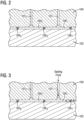
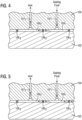
- FIGs. 2 through 5 respectively illustrate zoomed-in views of a portion of the cross-sectional view shown in FIG. 1 that may be used for illustrating and describing certain non-limiting structural and/or operational relationships of features in the disclosed rotor structure.
- FIG. 2 illustrates an example where annular seals 106 1 , 106 2 and 106 3 are intact. That is, no seal malfunction is present in any of the annular seals. In this case, no fluid flow would develop in conduits 107 1 and 107 2 . This is essentially a static condition.
- FIG. 3 illustrates an example where annular seal 106 1 is broken and annular seals 106 2 and 106 3 are intact. That is, a seal malfunction is present in annular seal 106 1 .
- pressurized process fluid would pass through malfunctioning annular seal 106 1 into chamber 109 1 ; pressurized sealing fluid would flow into chamber 109 1 and this would be effective to inhibit further progress of the pressurized process fluid in chamber 109 1 , provided the internal pressure of the sealing fluid is relatively larger compared to the internal pressure of the process fluid passing into chamber 109 1 .
- FIG. 4 illustrates an example where annular seal 106 2 is broken and annular seals 106 1 and 106 3 are intact. That is, a seal malfunction is present in annular seal 106 2 . In this case, sealing fluid would pass through malfunctioning annular seal 106 2 and into chamber 109 2 , effectively forming a fluid buffer zone overlapping chambers 109 1 and 109 2 with venting through conduit 107 2 .
- FIG. 5 illustrates an example where annular seals 106 1 and 106 2 are broken and annular seal 106 3 is intact. That is, seal malfunctions are present in annular seals 106 1 and 106 2 . In this case, sealing fluid mixed with pressurized process fluid would pass through malfunctioning annular seal 106 2 and this mixture would be vented through conduit 107 2 . In this example, this mixture would not advance beyond chamber 109 2 .
- the alternating chambers 109 1 , 109 2 through 109 n-1 include at least one backup first chamber (e.g., the chamber connected to first conduit 107 4 fluidly coupled to receive the sealing fluid) relative to the first chamber 109 1 , which is disposed downstream of the backup chamber connected to first conduit 107 4 .
- the term downstream is indicative of the direction of process fluid flow between the pressurized process side and the atmospheric pressure side of the turbomachine.
- the alternating chambers 109 1 , 109 2 through 109 n-1 includes at least one backup second chamber (e.g., the chamber connected to second conduit 107 3 fluidly coupled for venting) relative to a second chamber 109 2 disposed downstream of the chamber connected to second conduit 107 3 .
- first chamber e.g., chamber 109 1
- the backup first chamber e.g., chamber 109 4
- the second chamber e.g., chamber 109 2
- the backup chamber e.g., chamber 109 3
- a first fluid flow may be established through the first conduit/s (e.g., conduits 107 1 ,107 4 ) to convey sealing fluid into the respective chamber in communication with the first conduit/s, and/or a second fluid flow is established through the second conduit/s (e.g., conduits 107 2 ,107 3 ) to permit venting of the respective chamber in communication with the second conduit/s.
- first conduit/s e.g., conduits 107 1 ,107 4
- second fluid flow is established through the second conduit/s (e.g., conduits 107 2 ,107 3 ) to permit venting of the respective chamber in communication with the second conduit/s.
- disclosed embodiments make use of innovative venting/sealing arrangements effective for venting the tie bolt rotor so that, for example, an incipient leakage of the process fluid can be monitored. Additionally, in operation disclosed embodiments are effective to, for example, convey to the tie bolt rotor a pressurized sealing fluid effective for reducing the likelihood of process fluid escaping to the atmosphere.
Landscapes
- Engineering & Computer Science (AREA)
- Mechanical Engineering (AREA)
- General Engineering & Computer Science (AREA)
- Structures Of Non-Positive Displacement Pumps (AREA)
Claims (12)
- Structure de rotor (100) pour une turbomachine, la structure de rotor comprenant :un boulon d'attache (102) qui s'étend axialement entre un côté processus sous pression et un côté pression atmosphérique de la turbomachine ;un arbre de liaison (1041) respectif fixé à une première extrémité du boulon d'attache ; la structure de rotor étant caractérisée parun premier agencement de ventilation/étanchéité comprenant :une pluralité de dispositifs d'étanchéité annulaires (106) axialement espacés agencés autour d'un segment du boulon d'attache en correspondance avec un segment (108) radialement vers l'intérieur de l'arbre de liaison (1041) respectif, dans laquelle chaque paire de dispositifs d'étanchéité voisins respectifs de la pluralité de dispositifs d'étanchéité annulaires (106) axialement espacés définit des côtés d'étanchéité d'une chambre (109) respective d'une pluralité de chambres (109) axialement séquentielles disposées entre le côté processus et le côté pression atmosphérique de la turbomachine ; etune pluralité de conduits (107) s'étendant à partir d'un segment (111) radialement vers l'extérieur de l'arbre de liaison (1041) respectif à travers l'arbre de liaison pour communiquer avec la pluralité de chambres (109) axialement séquentielles disposées entre le côté processus et le côté pression atmosphérique de la turbomachine, la pluralité de conduits (107) alternant entre un premier conduit (1071) couplé de manière fluidique au niveau du segment radialement vers l'extérieur de l'arbre de liaison respectif pour recevoir un fluide d'étanchéité et un deuxième conduit (1072) raccordé de manière fluidique au niveau du segment radialement vers l'extérieur de l'arbre de liaison (1041) respectif pour ventilation,dans laquelle, en réponse à l'écoulement d'un début de fuite d'un fluide de processus à travers un ou plusieurs dispositifs d'étanchéité annulaires de la pluralité de dispositifs d'étanchéité annulaires (106) axialement espacés, un premier écoulement de fluide est établi à travers le premier conduit (1071) pour transporter un fluide d'étanchéité dans la chambre (109) respective en communication avec le premier conduit (1071), et/ou un deuxième écoulement de fluide est établi à travers le deuxième conduit (1072) pour permettre une ventilation de la chambre (109) respective en communication avec le deuxième conduit (1072).
- Structure de rotor (100) selon la revendication 1, dans laquelle la pluralité de chambres (109) axialement séquentielles disposées entre le côté processus et le côté pression atmosphérique de la turbomachine définissent une séquence de chambres alternées entre une première chambre (1091) agencée pour recevoir un fluide d'étanchéité et une deuxième chambre (1092) agencée pour ventiler le début de fuite du fluide de processus.
- Structure de rotor (100) selon la revendication 2, dans laquelle la pluralité de chambres (109) axialement séquentielles inclut au moins une première chambre de secours relativement à une première chambre(1091) disposée en aval de l'au moins une première chambre de secours et au moins une deuxième chambre de secours relativement à une deuxième chambre (1092) disposée en aval de l'au moins une deuxième chambre de secours, dans laquelle la première chambre (1091) et la première chambre de secours sont chacune indépendamment agencées pour recevoir un fluide d'étanchéité, et dans laquelle la deuxième chambre (1092) et la deuxième chambre de secours sont chacune indépendamment agencées pour permettre une ventilation.
- Structure de rotor (100) selon la revendication 1, dans laquelle un système d'étanchéité à fluide sec (130) disposé autour du segment radialement vers l'extérieur de l'arbre de liaison (1041) respectif comprend une source du fluide d'étanchéité et une sortie de ventilation pour le début de fuite du fluide de processus.
- Structure de rotor (100) selon la revendication 1, dans laquelle la première extrémité du boulon d'attache (102) correspond au côté traitement sous pression de la turbomachine.
- Structure de rotor (100) selon la revendication 1, comprenant en outre un deuxième arbre de liaison (1042) fixé à une deuxième extrémité du boulon d'attache (102), la deuxième extrémité étant axialement opposée à la première extrémité du boulon d'attache ;
un deuxième agencement de ventilation/étanchéité comprenant :une pluralité supplémentaire de dispositifs d'étanchéité annulaires (106) axialement espacés agencés autour d'un segment du boulon d'attache (102) en correspondance avec un segment radialement vers l'intérieur du deuxième arbre de liaison (1042), dans laquelle chaque paire de dispositifs d'étanchéité voisins respectifs de la pluralité supplémentaire de dispositifs d'étanchéité annulaires (106) axialement espacés définit des côtés d'étanchéité d'une chambre (109) respective d'une pluralité supplémentaire de chambres (109) axialement séquentielles disposées entre le côté processus et le côté pression atmosphérique de la turbomachine ; etune pluralité supplémentaire de conduits (107) s'étendant à partir d'un segment radialement vers l'extérieur du deuxième arbre de liaison (1042) à travers le deuxième arbre de liaison (1042) pour communiquer avec la pluralité supplémentaire de chambres (109) axialement séquentielles disposées entre le côté processus et le côté pression atmosphérique de la turbomachine, la pluralité supplémentaire de conduits (107) alternant entre un premier conduit (1071) couplé de manière fluidique au niveau du segment radialement vers l'extérieur du deuxième arbre de liaison (1042) pour recevoir un fluide d'étanchéité supplémentaire et un deuxième conduit (1072) raccordé de manière fluidique au niveau du segment radialement vers l'extérieur du deuxième arbre de liaison (1042) pour ventilation,dans laquelle, en réponse à l'écoulement d'un début de fuite supplémentaire du fluide de processus à travers un ou plusieurs dispositifs d'étanchéité annulaires de la pluralité supplémentaire de dispositifs d'étanchéité annulaires (106) axialement espacés, un premier écoulement de fluide est établi à travers le premier conduit (1071) de la pluralité supplémentaire de conduits (107) pour transporter le fluide d'étanchéité supplémentaire dans la chambre (109) respective de la pluralité supplémentaire de chambres axialement séquentielles (109) en communication avec le premier conduit (1071), et un deuxième écoulement de fluide est établi à travers le deuxième conduit (1072) de la pluralité supplémentaire de conduits (107) raccordés pour permettre une ventilation de la chambre (109) respective en communication avec le deuxième conduit (1072). - Structure de rotor (100) selon la revendication 6, dans laquelle la deuxième extrémité du boulon d'attache (102) correspond au côté pression atmosphérique de la turbomachine.
- Structure de rotor (100) selon la revendication 6, comprenant en outre une pluralité d'étages (140) de rouets disposés entre les arbres de liaison (1041, 1042), la pluralité d'étages (140) de rouets supportés par le boulon d'attache (102).
- Structure de rotor (100) selon la revendication 8, comprenant en outre des structures (150) de dispositifs d'étanchéité respectives agencées pour coupler des étages (140) de roue contigus les uns aux autres.
- Structure de rotor (100) selon la revendication 9, dans laquelle les structures (150) de dispositifs d'étanchéité respectifs comprennent des structures de dispositifs d'étanchéité Hirth respectives.
- Structure de rotor (100) selon la revendication 1, comprenant en outre un moniteur de fuite (160) informatisé couplé au deuxième conduit (1072) pour surveiller une présence du début de fuite du fluide de processus.
- Compresseur centrifuge comprenant la structure de rotor (100) selon l'une quelconque des revendications précédentes.
Applications Claiming Priority (1)
| Application Number | Priority Date | Filing Date | Title |
|---|---|---|---|
| PCT/US2020/019779 WO2021173124A1 (fr) | 2020-02-26 | 2020-02-26 | Structure de rotor pour une turbomachine avec agencement de ventilation/étanchéité dans un boulon d'attache |
Publications (2)
| Publication Number | Publication Date |
|---|---|
| EP4093975A1 EP4093975A1 (fr) | 2022-11-30 |
| EP4093975B1 true EP4093975B1 (fr) | 2025-04-02 |
Family
ID=69846619
Family Applications (1)
| Application Number | Title | Priority Date | Filing Date |
|---|---|---|---|
| EP20712799.4A Active EP4093975B1 (fr) | 2020-02-26 | 2020-02-26 | Structure de rotor pour une turbomachine avec agencement de ventilation/étanchéité dans un boulon d'attache |
Country Status (4)
| Country | Link |
|---|---|
| US (1) | US11859631B2 (fr) |
| EP (1) | EP4093975B1 (fr) |
| CN (1) | CN115210475B (fr) |
| WO (1) | WO2021173124A1 (fr) |
Families Citing this family (3)
| Publication number | Priority date | Publication date | Assignee | Title |
|---|---|---|---|---|
| WO2023059321A1 (fr) * | 2021-10-06 | 2023-04-13 | Siemens Energy Global GmbH & Co. KG | Structure de rotor disposée dans une turbomachine, comprenant un ensemble joint d'étanchéité et procédé en liaison avec cette dernière |
| EP4490485A4 (fr) | 2022-03-11 | 2026-04-15 | Atlas Copco Mafi Trench Company Llc | Système et procédé d'étanchéification de barrière thermique |
| US20250179957A1 (en) * | 2023-12-05 | 2025-06-05 | Baker Hughes Oilfield Operations Llc | System for passing a driveshaft between hazardous and nonhazardous environments, and method |
Family Cites Families (15)
| Publication number | Priority date | Publication date | Assignee | Title |
|---|---|---|---|---|
| GB986500A (en) * | 1961-01-09 | 1965-03-17 | Halbergerhutte Ges Mit Beschra | Method of and arrangement for pressure tight guiding of a piston rod or plunger |
| FR2221982A5 (fr) * | 1973-03-14 | 1974-10-11 | Technip Etud Construction | |
| US4057371A (en) * | 1974-05-03 | 1977-11-08 | Norwalk-Turbo Inc. | Gas turbine driven high speed centrifugal compressor unit |
| SE459683B (sv) * | 1987-11-19 | 1989-07-24 | Abb Stal Ab | Gasturbin med laenkinfaestning av en taetningsring i en ledskovelkrans |
| DE19645272A1 (de) * | 1996-11-02 | 1998-05-07 | Asea Brown Boveri | Gasgekühlte elektrische Maschine |
| US20020104316A1 (en) * | 2000-11-03 | 2002-08-08 | Capstone Turbine Corporation | Ultra low emissions gas turbine cycle using variable combustion primary zone airflow control |
| US6601547B2 (en) * | 2001-10-15 | 2003-08-05 | Osama M. Al-Hawaj | Axial piston rotary power device |
| IT1399904B1 (it) * | 2010-04-21 | 2013-05-09 | Nuovo Pignone Spa | Rotore impilato con tirante e flangia imbullonata e metodo |
| US10006364B2 (en) * | 2014-08-20 | 2018-06-26 | United Technologies Corporation | Gas turbine rotors |
| DE102014226429A1 (de) * | 2014-12-18 | 2016-06-23 | Eagleburgmann Germany Gmbh & Co. Kg | Wellendichtungsanordnung einer Fluidmaschine sowie Verfahren zur Abdichtung einer Welle einer Fluidmaschine |
| EP3264011A4 (fr) * | 2015-04-27 | 2018-01-17 | Mitsubishi Heavy Industries Compressor Corporation | Système de récupération de gaz, système de compression et système de cycle frigorifique |
| US10208762B2 (en) * | 2016-10-10 | 2019-02-19 | Solar Turbines Incorporated | Swirl brakes for compressors with teeth-on-rotor seals |
| CN206682032U (zh) * | 2016-11-25 | 2017-11-28 | 沈阳鼓风机集团安装检修配件有限公司 | 高密封性氯化氢压缩机轴端密封装置 |
| US10968762B2 (en) * | 2018-11-19 | 2021-04-06 | General Electric Company | Seal assembly for a turbo machine |
| US11118469B2 (en) * | 2018-11-19 | 2021-09-14 | General Electric Company | Seal assembly for a turbo machine |
-
2020
- 2020-02-26 EP EP20712799.4A patent/EP4093975B1/fr active Active
- 2020-02-26 CN CN202080097671.8A patent/CN115210475B/zh active Active
- 2020-02-26 US US17/779,584 patent/US11859631B2/en active Active
- 2020-02-26 WO PCT/US2020/019779 patent/WO2021173124A1/fr not_active Ceased
Also Published As
| Publication number | Publication date |
|---|---|
| CN115210475A (zh) | 2022-10-18 |
| WO2021173124A1 (fr) | 2021-09-02 |
| US20230003225A1 (en) | 2023-01-05 |
| US11859631B2 (en) | 2024-01-02 |
| EP4093975A1 (fr) | 2022-11-30 |
| CN115210475B (zh) | 2025-09-30 |
Similar Documents
| Publication | Publication Date | Title |
|---|---|---|
| EP4093975B1 (fr) | Structure de rotor pour une turbomachine avec agencement de ventilation/étanchéité dans un boulon d'attache | |
| US9279324B2 (en) | Reduced leakage balance piston seal | |
| EP2631489B1 (fr) | Compresseur | |
| EP2098686B1 (fr) | Turbine à gaz à deux arbres | |
| US4816213A (en) | Thermal distortion isolation system for turbine blade rings | |
| EP3019778B1 (fr) | Compresseur avec joint annulaire | |
| US9488187B2 (en) | Seal assembly for centrifugal compressors | |
| CN114787544A (zh) | 用于机器的复合密封结构和制造复合密封结构的方法 | |
| EP2971615B1 (fr) | Segment de conduit à faible niveau de fuite utilisant un ensemble joint de dilatation | |
| US20150369074A1 (en) | Compressor aft hub sealing system | |
| EP2279353B1 (fr) | Récupération de gaz de fuite d'un extenseur-accélérateur | |
| CN118188810A (zh) | 一种负压组合式密封装置 | |
| US11885340B2 (en) | Compressor rotor structure | |
| US20170191486A1 (en) | Fluid energy machine having a tandem dry gas seal | |
| US9540942B2 (en) | Shaft sealing system for steam turbines | |
| KR20020028221A (ko) | 터빈 및 누출 유체를 방출시키기 위한 방법 | |
| JP7358660B2 (ja) | 締め付けボルト内に流動ループを有するコンプレッサ用ロータ | |
| CN103375189B (zh) | 用于蒸汽涡轮的轴密封系统 | |
| EP3126678B1 (fr) | Joint d'étanchéité de registre pour agencement de compresseur à double écoulement | |
| US12055152B1 (en) | In a turbomachine, rotor structure with seal assembly and method in connection with same | |
| KR102471025B1 (ko) | 플로팅 링 실 | |
| CN116201604A (zh) | 一种自适应弹性变形轴类连接结构及发动机转子组件 | |
| US20210285331A1 (en) | Turbine stator blade | |
| JP2005233080A (ja) | ガスタービン | |
| EP3960999B1 (fr) | Turbine à gaz et procédé de fabrication d'une turbine à gaz |
Legal Events
| Date | Code | Title | Description |
|---|---|---|---|
| STAA | Information on the status of an ep patent application or granted ep patent |
Free format text: STATUS: UNKNOWN |
|
| STAA | Information on the status of an ep patent application or granted ep patent |
Free format text: STATUS: THE INTERNATIONAL PUBLICATION HAS BEEN MADE |
|
| PUAI | Public reference made under article 153(3) epc to a published international application that has entered the european phase |
Free format text: ORIGINAL CODE: 0009012 |
|
| STAA | Information on the status of an ep patent application or granted ep patent |
Free format text: STATUS: REQUEST FOR EXAMINATION WAS MADE |
|
| 17P | Request for examination filed |
Effective date: 20220824 |
|
| AK | Designated contracting states |
Kind code of ref document: A1 Designated state(s): AL AT BE BG CH CY CZ DE DK EE ES FI FR GB GR HR HU IE IS IT LI LT LU LV MC MK MT NL NO PL PT RO RS SE SI SK SM TR |
|
| RAP3 | Party data changed (applicant data changed or rights of an application transferred) |
Owner name: SIEMENS ENERGY GLOBAL GMBH & CO. KG |
|
| DAV | Request for validation of the european patent (deleted) | ||
| DAX | Request for extension of the european patent (deleted) | ||
| GRAP | Despatch of communication of intention to grant a patent |
Free format text: ORIGINAL CODE: EPIDOSNIGR1 |
|
| STAA | Information on the status of an ep patent application or granted ep patent |
Free format text: STATUS: GRANT OF PATENT IS INTENDED |
|
| INTG | Intention to grant announced |
Effective date: 20241024 |
|
| GRAS | Grant fee paid |
Free format text: ORIGINAL CODE: EPIDOSNIGR3 |
|
| GRAA | (expected) grant |
Free format text: ORIGINAL CODE: 0009210 |
|
| STAA | Information on the status of an ep patent application or granted ep patent |
Free format text: STATUS: THE PATENT HAS BEEN GRANTED |
|
| AK | Designated contracting states |
Kind code of ref document: B1 Designated state(s): AL AT BE BG CH CY CZ DE DK EE ES FI FR GB GR HR HU IE IS IT LI LT LU LV MC MK MT NL NO PL PT RO RS SE SI SK SM TR |
|
| REG | Reference to a national code |
Ref country code: GB Ref legal event code: FG4D |
|
| REG | Reference to a national code |
Ref country code: CH Ref legal event code: EP |
|
| REG | Reference to a national code |
Ref country code: IE Ref legal event code: FG4D |
|
| REG | Reference to a national code |
Ref country code: DE Ref legal event code: R096 Ref document number: 602020048679 Country of ref document: DE |
|
| REG | Reference to a national code |
Ref country code: NL Ref legal event code: MP Effective date: 20250402 |
|
| PG25 | Lapsed in a contracting state [announced via postgrant information from national office to epo] |
Ref country code: NL Free format text: LAPSE BECAUSE OF FAILURE TO SUBMIT A TRANSLATION OF THE DESCRIPTION OR TO PAY THE FEE WITHIN THE PRESCRIBED TIME-LIMIT Effective date: 20250402 |
|
| REG | Reference to a national code |
Ref country code: AT Ref legal event code: MK05 Ref document number: 1781499 Country of ref document: AT Kind code of ref document: T Effective date: 20250402 |
|
| PG25 | Lapsed in a contracting state [announced via postgrant information from national office to epo] |
Ref country code: ES Free format text: LAPSE BECAUSE OF FAILURE TO SUBMIT A TRANSLATION OF THE DESCRIPTION OR TO PAY THE FEE WITHIN THE PRESCRIBED TIME-LIMIT Effective date: 20250402 Ref country code: PT Free format text: LAPSE BECAUSE OF FAILURE TO SUBMIT A TRANSLATION OF THE DESCRIPTION OR TO PAY THE FEE WITHIN THE PRESCRIBED TIME-LIMIT Effective date: 20250804 Ref country code: FI Free format text: LAPSE BECAUSE OF FAILURE TO SUBMIT A TRANSLATION OF THE DESCRIPTION OR TO PAY THE FEE WITHIN THE PRESCRIBED TIME-LIMIT Effective date: 20250402 |
|
| REG | Reference to a national code |
Ref country code: LT Ref legal event code: MG9D |
|
| PG25 | Lapsed in a contracting state [announced via postgrant information from national office to epo] |
Ref country code: NO Free format text: LAPSE BECAUSE OF FAILURE TO SUBMIT A TRANSLATION OF THE DESCRIPTION OR TO PAY THE FEE WITHIN THE PRESCRIBED TIME-LIMIT Effective date: 20250702 Ref country code: GR Free format text: LAPSE BECAUSE OF FAILURE TO SUBMIT A TRANSLATION OF THE DESCRIPTION OR TO PAY THE FEE WITHIN THE PRESCRIBED TIME-LIMIT Effective date: 20250703 |
|
| PG25 | Lapsed in a contracting state [announced via postgrant information from national office to epo] |
Ref country code: PL Free format text: LAPSE BECAUSE OF FAILURE TO SUBMIT A TRANSLATION OF THE DESCRIPTION OR TO PAY THE FEE WITHIN THE PRESCRIBED TIME-LIMIT Effective date: 20250402 |
|
| PG25 | Lapsed in a contracting state [announced via postgrant information from national office to epo] |
Ref country code: BG Free format text: LAPSE BECAUSE OF FAILURE TO SUBMIT A TRANSLATION OF THE DESCRIPTION OR TO PAY THE FEE WITHIN THE PRESCRIBED TIME-LIMIT Effective date: 20250402 |
|
| PG25 | Lapsed in a contracting state [announced via postgrant information from national office to epo] |
Ref country code: HR Free format text: LAPSE BECAUSE OF FAILURE TO SUBMIT A TRANSLATION OF THE DESCRIPTION OR TO PAY THE FEE WITHIN THE PRESCRIBED TIME-LIMIT Effective date: 20250402 |
|
| PG25 | Lapsed in a contracting state [announced via postgrant information from national office to epo] |
Ref country code: AT Free format text: LAPSE BECAUSE OF FAILURE TO SUBMIT A TRANSLATION OF THE DESCRIPTION OR TO PAY THE FEE WITHIN THE PRESCRIBED TIME-LIMIT Effective date: 20250402 |
|
| PG25 | Lapsed in a contracting state [announced via postgrant information from national office to epo] |
Ref country code: RS Free format text: LAPSE BECAUSE OF FAILURE TO SUBMIT A TRANSLATION OF THE DESCRIPTION OR TO PAY THE FEE WITHIN THE PRESCRIBED TIME-LIMIT Effective date: 20250702 |
|
| PG25 | Lapsed in a contracting state [announced via postgrant information from national office to epo] |
Ref country code: IS Free format text: LAPSE BECAUSE OF FAILURE TO SUBMIT A TRANSLATION OF THE DESCRIPTION OR TO PAY THE FEE WITHIN THE PRESCRIBED TIME-LIMIT Effective date: 20250802 |
|
| PG25 | Lapsed in a contracting state [announced via postgrant information from national office to epo] |
Ref country code: LV Free format text: LAPSE BECAUSE OF FAILURE TO SUBMIT A TRANSLATION OF THE DESCRIPTION OR TO PAY THE FEE WITHIN THE PRESCRIBED TIME-LIMIT Effective date: 20250402 |
|
| REG | Reference to a national code |
Ref country code: DE Ref legal event code: R097 Ref document number: 602020048679 Country of ref document: DE |
|
| PG25 | Lapsed in a contracting state [announced via postgrant information from national office to epo] |
Ref country code: SM Free format text: LAPSE BECAUSE OF FAILURE TO SUBMIT A TRANSLATION OF THE DESCRIPTION OR TO PAY THE FEE WITHIN THE PRESCRIBED TIME-LIMIT Effective date: 20250402 Ref country code: DK Free format text: LAPSE BECAUSE OF FAILURE TO SUBMIT A TRANSLATION OF THE DESCRIPTION OR TO PAY THE FEE WITHIN THE PRESCRIBED TIME-LIMIT Effective date: 20250402 |
|
| PG25 | Lapsed in a contracting state [announced via postgrant information from national office to epo] |
Ref country code: CZ Free format text: LAPSE BECAUSE OF FAILURE TO SUBMIT A TRANSLATION OF THE DESCRIPTION OR TO PAY THE FEE WITHIN THE PRESCRIBED TIME-LIMIT Effective date: 20250402 |
|
| PG25 | Lapsed in a contracting state [announced via postgrant information from national office to epo] |
Ref country code: EE Free format text: LAPSE BECAUSE OF FAILURE TO SUBMIT A TRANSLATION OF THE DESCRIPTION OR TO PAY THE FEE WITHIN THE PRESCRIBED TIME-LIMIT Effective date: 20250402 |
|
| PG25 | Lapsed in a contracting state [announced via postgrant information from national office to epo] |
Ref country code: SK Free format text: LAPSE BECAUSE OF FAILURE TO SUBMIT A TRANSLATION OF THE DESCRIPTION OR TO PAY THE FEE WITHIN THE PRESCRIBED TIME-LIMIT Effective date: 20250402 |
|
| PLBE | No opposition filed within time limit |
Free format text: ORIGINAL CODE: 0009261 |
|
| STAA | Information on the status of an ep patent application or granted ep patent |
Free format text: STATUS: NO OPPOSITION FILED WITHIN TIME LIMIT |
|
| REG | Reference to a national code |
Ref country code: CH Ref legal event code: L10 Free format text: ST27 STATUS EVENT CODE: U-0-0-L10-L00 (AS PROVIDED BY THE NATIONAL OFFICE) Effective date: 20260211 |
|
| REG | Reference to a national code |
Ref country code: CH Ref legal event code: U11 Free format text: ST27 STATUS EVENT CODE: U-0-0-U10-U11 (AS PROVIDED BY THE NATIONAL OFFICE) Effective date: 20260301 |
|
| 26N | No opposition filed |
Effective date: 20260105 |
|
| PGFP | Annual fee paid to national office [announced via postgrant information from national office to epo] |
Ref country code: DE Payment date: 20260220 Year of fee payment: 7 |
|
| PGFP | Annual fee paid to national office [announced via postgrant information from national office to epo] |
Ref country code: IT Payment date: 20260220 Year of fee payment: 7 |
|
| PGFP | Annual fee paid to national office [announced via postgrant information from national office to epo] |
Ref country code: FR Payment date: 20260224 Year of fee payment: 7 |