EP4093982B1 - Transfert ou transmission de signal dans un instrument chirurgical - Google Patents
Transfert ou transmission de signal dans un instrument chirurgical Download PDFInfo
- Publication number
- EP4093982B1 EP4093982B1 EP21701438.0A EP21701438A EP4093982B1 EP 4093982 B1 EP4093982 B1 EP 4093982B1 EP 21701438 A EP21701438 A EP 21701438A EP 4093982 B1 EP4093982 B1 EP 4093982B1
- Authority
- EP
- European Patent Office
- Prior art keywords
- sleeve
- signal line
- signal
- surgical instrument
- roller bearing
- Prior art date
- Legal status (The legal status is an assumption and is not a legal conclusion. Google has not performed a legal analysis and makes no representation as to the accuracy of the status listed.)
- Active
Links
Images


Classifications
-
- A—HUMAN NECESSITIES
- A61—MEDICAL OR VETERINARY SCIENCE; HYGIENE
- A61B—DIAGNOSIS; SURGERY; IDENTIFICATION
- A61B17/00—Surgical instruments, devices or methods
- A61B17/16—Instruments for performing osteoclasis; Drills or chisels for bones; Trepans
- A61B17/1613—Component parts
- A61B17/1633—Sleeves, i.e. non-rotating parts surrounding the bit shaft, e.g. the sleeve forming a single unit with the bit shaft
-
- A—HUMAN NECESSITIES
- A61—MEDICAL OR VETERINARY SCIENCE; HYGIENE
- A61B—DIAGNOSIS; SURGERY; IDENTIFICATION
- A61B17/00—Surgical instruments, devices or methods
- A61B17/16—Instruments for performing osteoclasis; Drills or chisels for bones; Trepans
- A61B17/1613—Component parts
- A61B17/1622—Drill handpieces
-
- A—HUMAN NECESSITIES
- A61—MEDICAL OR VETERINARY SCIENCE; HYGIENE
- A61B—DIAGNOSIS; SURGERY; IDENTIFICATION
- A61B17/00—Surgical instruments, devices or methods
- A61B17/16—Instruments for performing osteoclasis; Drills or chisels for bones; Trepans
- A61B17/1613—Component parts
- A61B17/1622—Drill handpieces
- A61B17/1624—Drive mechanisms therefor
-
- A—HUMAN NECESSITIES
- A61—MEDICAL OR VETERINARY SCIENCE; HYGIENE
- A61B—DIAGNOSIS; SURGERY; IDENTIFICATION
- A61B17/00—Surgical instruments, devices or methods
- A61B17/16—Instruments for performing osteoclasis; Drills or chisels for bones; Trepans
- A61B17/1613—Component parts
- A61B17/1626—Control means; Display units
-
- F—MECHANICAL ENGINEERING; LIGHTING; HEATING; WEAPONS; BLASTING
- F16—ENGINEERING ELEMENTS AND UNITS; GENERAL MEASURES FOR PRODUCING AND MAINTAINING EFFECTIVE FUNCTIONING OF MACHINES OR INSTALLATIONS; THERMAL INSULATION IN GENERAL
- F16C—SHAFTS; FLEXIBLE SHAFTS; ELEMENTS OR CRANKSHAFT MECHANISMS; ROTARY BODIES OTHER THAN GEARING ELEMENTS; BEARINGS
- F16C19/00—Bearings with rolling contact, for exclusively rotary movement
- F16C19/02—Bearings with rolling contact, for exclusively rotary movement with bearing balls essentially of the same size in one or more circular rows
- F16C19/04—Bearings with rolling contact, for exclusively rotary movement with bearing balls essentially of the same size in one or more circular rows for radial load mainly
- F16C19/06—Bearings with rolling contact, for exclusively rotary movement with bearing balls essentially of the same size in one or more circular rows for radial load mainly with a single row or balls
-
- F—MECHANICAL ENGINEERING; LIGHTING; HEATING; WEAPONS; BLASTING
- F16—ENGINEERING ELEMENTS AND UNITS; GENERAL MEASURES FOR PRODUCING AND MAINTAINING EFFECTIVE FUNCTIONING OF MACHINES OR INSTALLATIONS; THERMAL INSULATION IN GENERAL
- F16C—SHAFTS; FLEXIBLE SHAFTS; ELEMENTS OR CRANKSHAFT MECHANISMS; ROTARY BODIES OTHER THAN GEARING ELEMENTS; BEARINGS
- F16C19/00—Bearings with rolling contact, for exclusively rotary movement
- F16C19/54—Systems consisting of a plurality of bearings with rolling friction
-
- F—MECHANICAL ENGINEERING; LIGHTING; HEATING; WEAPONS; BLASTING
- F16—ENGINEERING ELEMENTS AND UNITS; GENERAL MEASURES FOR PRODUCING AND MAINTAINING EFFECTIVE FUNCTIONING OF MACHINES OR INSTALLATIONS; THERMAL INSULATION IN GENERAL
- F16C—SHAFTS; FLEXIBLE SHAFTS; ELEMENTS OR CRANKSHAFT MECHANISMS; ROTARY BODIES OTHER THAN GEARING ELEMENTS; BEARINGS
- F16C33/00—Parts of bearings; Special methods for making bearings or parts thereof
- F16C33/30—Parts of ball or roller bearings
- F16C33/58—Raceways; Race rings
- F16C33/583—Details of specific parts of races
- F16C33/586—Details of specific parts of races outside the space between the races, e.g. end faces or bore of inner ring
-
- F—MECHANICAL ENGINEERING; LIGHTING; HEATING; WEAPONS; BLASTING
- F16—ENGINEERING ELEMENTS AND UNITS; GENERAL MEASURES FOR PRODUCING AND MAINTAINING EFFECTIVE FUNCTIONING OF MACHINES OR INSTALLATIONS; THERMAL INSULATION IN GENERAL
- F16C—SHAFTS; FLEXIBLE SHAFTS; ELEMENTS OR CRANKSHAFT MECHANISMS; ROTARY BODIES OTHER THAN GEARING ELEMENTS; BEARINGS
- F16C33/00—Parts of bearings; Special methods for making bearings or parts thereof
- F16C33/30—Parts of ball or roller bearings
- F16C33/58—Raceways; Race rings
- F16C33/62—Selection of substances
-
- F—MECHANICAL ENGINEERING; LIGHTING; HEATING; WEAPONS; BLASTING
- F16—ENGINEERING ELEMENTS AND UNITS; GENERAL MEASURES FOR PRODUCING AND MAINTAINING EFFECTIVE FUNCTIONING OF MACHINES OR INSTALLATIONS; THERMAL INSULATION IN GENERAL
- F16C—SHAFTS; FLEXIBLE SHAFTS; ELEMENTS OR CRANKSHAFT MECHANISMS; ROTARY BODIES OTHER THAN GEARING ELEMENTS; BEARINGS
- F16C33/00—Parts of bearings; Special methods for making bearings or parts thereof
- F16C33/30—Parts of ball or roller bearings
- F16C33/58—Raceways; Race rings
- F16C33/64—Special methods of manufacture
-
- F—MECHANICAL ENGINEERING; LIGHTING; HEATING; WEAPONS; BLASTING
- F16—ENGINEERING ELEMENTS AND UNITS; GENERAL MEASURES FOR PRODUCING AND MAINTAINING EFFECTIVE FUNCTIONING OF MACHINES OR INSTALLATIONS; THERMAL INSULATION IN GENERAL
- F16C—SHAFTS; FLEXIBLE SHAFTS; ELEMENTS OR CRANKSHAFT MECHANISMS; ROTARY BODIES OTHER THAN GEARING ELEMENTS; BEARINGS
- F16C35/00—Rigid support of bearing units; Housings, e.g. caps, covers
- F16C35/04—Rigid support of bearing units; Housings, e.g. caps, covers in the case of ball or roller bearings
- F16C35/06—Mounting or dismounting of ball or roller bearings; Fixing them onto shaft or in housing
- F16C35/067—Fixing them in a housing
-
- F—MECHANICAL ENGINEERING; LIGHTING; HEATING; WEAPONS; BLASTING
- F16—ENGINEERING ELEMENTS AND UNITS; GENERAL MEASURES FOR PRODUCING AND MAINTAINING EFFECTIVE FUNCTIONING OF MACHINES OR INSTALLATIONS; THERMAL INSULATION IN GENERAL
- F16C—SHAFTS; FLEXIBLE SHAFTS; ELEMENTS OR CRANKSHAFT MECHANISMS; ROTARY BODIES OTHER THAN GEARING ELEMENTS; BEARINGS
- F16C41/00—Other accessories, e.g. devices integrated in the bearing not relating to the bearing function as such
- F16C41/002—Conductive elements, e.g. to prevent static electricity
-
- F—MECHANICAL ENGINEERING; LIGHTING; HEATING; WEAPONS; BLASTING
- F16—ENGINEERING ELEMENTS AND UNITS; GENERAL MEASURES FOR PRODUCING AND MAINTAINING EFFECTIVE FUNCTIONING OF MACHINES OR INSTALLATIONS; THERMAL INSULATION IN GENERAL
- F16C—SHAFTS; FLEXIBLE SHAFTS; ELEMENTS OR CRANKSHAFT MECHANISMS; ROTARY BODIES OTHER THAN GEARING ELEMENTS; BEARINGS
- F16C41/00—Other accessories, e.g. devices integrated in the bearing not relating to the bearing function as such
- F16C41/008—Identification means, e.g. markings, RFID-tags; Data transfer means
-
- H—ELECTRICITY
- H01—ELECTRIC ELEMENTS
- H01R—ELECTRICALLY-CONDUCTIVE CONNECTIONS; STRUCTURAL ASSOCIATIONS OF A PLURALITY OF MUTUALLY-INSULATED ELECTRICAL CONNECTING ELEMENTS; COUPLING DEVICES; CURRENT COLLECTORS
- H01R39/00—Rotary current collectors, distributors or interrupters
- H01R39/64—Devices for uninterrupted current collection
- H01R39/643—Devices for uninterrupted current collection through ball or roller bearing
-
- A—HUMAN NECESSITIES
- A61—MEDICAL OR VETERINARY SCIENCE; HYGIENE
- A61B—DIAGNOSIS; SURGERY; IDENTIFICATION
- A61B17/00—Surgical instruments, devices or methods
- A61B2017/00017—Electrical control of surgical instruments
- A61B2017/00022—Sensing or detecting at the treatment site
- A61B2017/00084—Temperature
-
- A—HUMAN NECESSITIES
- A61—MEDICAL OR VETERINARY SCIENCE; HYGIENE
- A61B—DIAGNOSIS; SURGERY; IDENTIFICATION
- A61B17/00—Surgical instruments, devices or methods
- A61B2017/00017—Electrical control of surgical instruments
- A61B2017/00137—Details of operation mode
-
- A—HUMAN NECESSITIES
- A61—MEDICAL OR VETERINARY SCIENCE; HYGIENE
- A61B—DIAGNOSIS; SURGERY; IDENTIFICATION
- A61B17/00—Surgical instruments, devices or methods
- A61B2017/00477—Coupling
-
- A—HUMAN NECESSITIES
- A61—MEDICAL OR VETERINARY SCIENCE; HYGIENE
- A61B—DIAGNOSIS; SURGERY; IDENTIFICATION
- A61B17/00—Surgical instruments, devices or methods
- A61B17/16—Instruments for performing osteoclasis; Drills or chisels for bones; Trepans
- A61B2017/1602—Mills
-
- F—MECHANICAL ENGINEERING; LIGHTING; HEATING; WEAPONS; BLASTING
- F16—ENGINEERING ELEMENTS AND UNITS; GENERAL MEASURES FOR PRODUCING AND MAINTAINING EFFECTIVE FUNCTIONING OF MACHINES OR INSTALLATIONS; THERMAL INSULATION IN GENERAL
- F16C—SHAFTS; FLEXIBLE SHAFTS; ELEMENTS OR CRANKSHAFT MECHANISMS; ROTARY BODIES OTHER THAN GEARING ELEMENTS; BEARINGS
- F16C2202/00—Solid materials defined by their properties
- F16C2202/30—Electric properties; Magnetic properties
- F16C2202/32—Conductivity
-
- F—MECHANICAL ENGINEERING; LIGHTING; HEATING; WEAPONS; BLASTING
- F16—ENGINEERING ELEMENTS AND UNITS; GENERAL MEASURES FOR PRODUCING AND MAINTAINING EFFECTIVE FUNCTIONING OF MACHINES OR INSTALLATIONS; THERMAL INSULATION IN GENERAL
- F16C—SHAFTS; FLEXIBLE SHAFTS; ELEMENTS OR CRANKSHAFT MECHANISMS; ROTARY BODIES OTHER THAN GEARING ELEMENTS; BEARINGS
- F16C2220/00—Shaping
- F16C2220/60—Shaping by removing material, e.g. machining
- F16C2220/62—Shaping by removing material, e.g. machining by turning, boring, drilling
-
- F—MECHANICAL ENGINEERING; LIGHTING; HEATING; WEAPONS; BLASTING
- F16—ENGINEERING ELEMENTS AND UNITS; GENERAL MEASURES FOR PRODUCING AND MAINTAINING EFFECTIVE FUNCTIONING OF MACHINES OR INSTALLATIONS; THERMAL INSULATION IN GENERAL
- F16C—SHAFTS; FLEXIBLE SHAFTS; ELEMENTS OR CRANKSHAFT MECHANISMS; ROTARY BODIES OTHER THAN GEARING ELEMENTS; BEARINGS
- F16C2226/00—Joining parts; Fastening; Assembling or mounting parts
- F16C2226/30—Material joints
- F16C2226/40—Material joints with adhesive
-
- F—MECHANICAL ENGINEERING; LIGHTING; HEATING; WEAPONS; BLASTING
- F16—ENGINEERING ELEMENTS AND UNITS; GENERAL MEASURES FOR PRODUCING AND MAINTAINING EFFECTIVE FUNCTIONING OF MACHINES OR INSTALLATIONS; THERMAL INSULATION IN GENERAL
- F16C—SHAFTS; FLEXIBLE SHAFTS; ELEMENTS OR CRANKSHAFT MECHANISMS; ROTARY BODIES OTHER THAN GEARING ELEMENTS; BEARINGS
- F16C2226/00—Joining parts; Fastening; Assembling or mounting parts
- F16C2226/50—Positive connections
- F16C2226/52—Positive connections with plastic deformation, e.g. caulking or staking
-
- F—MECHANICAL ENGINEERING; LIGHTING; HEATING; WEAPONS; BLASTING
- F16—ENGINEERING ELEMENTS AND UNITS; GENERAL MEASURES FOR PRODUCING AND MAINTAINING EFFECTIVE FUNCTIONING OF MACHINES OR INSTALLATIONS; THERMAL INSULATION IN GENERAL
- F16C—SHAFTS; FLEXIBLE SHAFTS; ELEMENTS OR CRANKSHAFT MECHANISMS; ROTARY BODIES OTHER THAN GEARING ELEMENTS; BEARINGS
- F16C2240/00—Specified values or numerical ranges of parameters; Relations between them
- F16C2240/40—Linear dimensions, e.g. length, radius, thickness, gap
- F16C2240/44—Hole or pocket sizes
-
- F—MECHANICAL ENGINEERING; LIGHTING; HEATING; WEAPONS; BLASTING
- F16—ENGINEERING ELEMENTS AND UNITS; GENERAL MEASURES FOR PRODUCING AND MAINTAINING EFFECTIVE FUNCTIONING OF MACHINES OR INSTALLATIONS; THERMAL INSULATION IN GENERAL
- F16C—SHAFTS; FLEXIBLE SHAFTS; ELEMENTS OR CRANKSHAFT MECHANISMS; ROTARY BODIES OTHER THAN GEARING ELEMENTS; BEARINGS
- F16C2300/00—Application independent of particular apparatuses
- F16C2300/10—Application independent of particular apparatuses related to size
- F16C2300/12—Small applications, e.g. miniature bearings
-
- F—MECHANICAL ENGINEERING; LIGHTING; HEATING; WEAPONS; BLASTING
- F16—ENGINEERING ELEMENTS AND UNITS; GENERAL MEASURES FOR PRODUCING AND MAINTAINING EFFECTIVE FUNCTIONING OF MACHINES OR INSTALLATIONS; THERMAL INSULATION IN GENERAL
- F16C—SHAFTS; FLEXIBLE SHAFTS; ELEMENTS OR CRANKSHAFT MECHANISMS; ROTARY BODIES OTHER THAN GEARING ELEMENTS; BEARINGS
- F16C2316/00—Apparatus in health or amusement
- F16C2316/10—Apparatus in health or amusement in medical appliances, e.g. in diagnosis, dentistry, instruments, prostheses, medical imaging appliances
-
- H—ELECTRICITY
- H01—ELECTRIC ELEMENTS
- H01R—ELECTRICALLY-CONDUCTIVE CONNECTIONS; STRUCTURAL ASSOCIATIONS OF A PLURALITY OF MUTUALLY-INSULATED ELECTRICAL CONNECTING ELEMENTS; COUPLING DEVICES; CURRENT COLLECTORS
- H01R2201/00—Connectors or connections adapted for particular applications
- H01R2201/12—Connectors or connections adapted for particular applications for medicine and surgery
-
- H—ELECTRICITY
- H01—ELECTRIC ELEMENTS
- H01R—ELECTRICALLY-CONDUCTIVE CONNECTIONS; STRUCTURAL ASSOCIATIONS OF A PLURALITY OF MUTUALLY-INSULATED ELECTRICAL CONNECTING ELEMENTS; COUPLING DEVICES; CURRENT COLLECTORS
- H01R24/00—Two-part coupling devices, or either of their cooperating parts, characterised by their overall structure
- H01R24/86—Parallel contacts arranged about a common axis
-
- H—ELECTRICITY
- H01—ELECTRIC ELEMENTS
- H01R—ELECTRICALLY-CONDUCTIVE CONNECTIONS; STRUCTURAL ASSOCIATIONS OF A PLURALITY OF MUTUALLY-INSULATED ELECTRICAL CONNECTING ELEMENTS; COUPLING DEVICES; CURRENT COLLECTORS
- H01R31/00—Coupling parts supported only by co-operation with counterpart
- H01R31/06—Intermediate parts for linking two coupling parts, e.g. adapter
- H01R31/065—Intermediate parts for linking two coupling parts, e.g. adapter with built-in electric apparatus
Definitions
- the present invention relates to signal forwarding or transmission in a surgical instrument, for example a milling handpiece.
- the present invention relates to a surgical instrument with a rolling bearing, a method for producing a rolling bearing and a use of a rolling bearing in a surgical instrument.
- Surgical motor systems that is, surgical instruments that have a motor, such as milling handpieces, are increasingly being equipped with new functions that require transmission, forwarding or transmission of electrical signals.
- Such new functions can be, for example, that a temperature at a tip of the milling handpiece is determined via temperature sensors, that forces during milling are determined via strain gauges, or that a type of tool inserted into the milling handpiece is identified via sensors or antennas, for example RFID or NFC readout antennas becomes.
- What these new functions have in common is that they require an electrical connection to a control unit in order to transmit, forward or transfer data.
- Such an electrical connection has so far been implemented, for example, by attaching or inserting signal lines into the milling handpiece.
- Electrical signals are transmitted via individual, insulated signal strands, which run in a separate channel through the shaft of the milling handpiece and extend to a tip/distal end of the milling handpiece.
- introducing or inserting conventional signal lines into the milling handpiece means that an outer diameter of a shaft of the milling handpiece must be increased since an additional channel is required for the insulated signal strands.
- the DE 10 2015 007593 A1 discloses a wheel bearing for a vehicle with heating elements that are supplied with electrical energy via electrical supply lines.
- the heating elements serve to heat up the wheel bearing and are intended to reduce bearing friction and bearing wear.
- the DE 10 2008 016592 A1 discloses a measuring bearing for a wheelset of a rail vehicle, which reliably measures the actual loads on the bearing. Sensors designed as strain gauges are provided, as well as signal lines which are guided in grooves.
- the EP 2 589 347 A1 discloses a surgical gripping instrument with a hollow cylindrical component through which signal lines run. Furthermore, the reveals DE 698 08 255 T2 a sheath that can be attached to a surgical instrument and has conductors for transmitting electrical signals. In addition, the reveals CN 204 394 449 U a socket or sleeve, which is intended for image capture in vivo in animal experiments and has electrodes for signal capture/transmission/forwarding through the sleeve.
- the US 2018/064438 A1 , the WO 2014/116782 A1 and the US 2014/074084 A1 each reveal sleeve-shaped components through which cables/signal lines run.
- signal lines or signal paths should be better integrated into the existing structure of surgical (motor) instruments such as milling handpieces, without thereby changing the dimensions of the surgical instrument or the components provided in the instrument, i.e. without, for example, increasing the outer diameter of the surgical instrument.
- a new design of a rolling bearing and a sleeve which enables a forwarding/transmission/transmission of electrical signals through the rolling bearing and the sleeve, as well as between these components, with the dimensions of the components (rolling bearing and sleeve) remaining unchanged, see above that the outer diameter of the surgical instrument is not increased.
- the surgical instrument therefore retains its compact design and the existing installation space is appropriately utilized.
- the disclosure initially relates to a rolling bearing, in particular a ball bearing, which is set up for the, preferably multidirectional, forwarding or transmission of electrical signals and for this purpose has at least one signal line or signal path integrated into the ball bearing.
- the disclosure basically relates to a rolling bearing and is therefore not limited to a ball bearing, that is, any other rolling bearings such as cylindrical roller bearings, needle bearings, tapered roller bearings, barrel bearings, toroidal roller bearings, etc. should also be included in the disclosure.
- the ball bearing represents the preferred embodiment of a rolling bearing according to the present disclosure.
- the ball bearing is a micro-ball bearing.
- the roller bearing/ball bearing is preferably set up or suitable or intended for use in a surgical (motor) instrument, in particular a surgical handpiece, in particular a milling handpiece.
- the signal line or signal track is integrated in an outer ring of the roller bearing/ball bearing.
- the rolling bearing/ball bearing (in particular the outer ring of the rolling bearing/ball bearing) is preferably made of a non-conductive material. More preferably, the material of the rolling bearing/ball bearing (the outer ring) is a hard material. Ceramics have proven to be particularly suitable.
- the signal line or signal track is preferably made of a (good) conductive material, in particular copper, silver or gold.
- An advantageous exemplary embodiment is characterized in that at least one signal line, in particular signal wire, is provided, which enters a hole provided in the rolling bearing/ball bearing, in particular the outer ring of the rolling bearing/ball bearing, which extends over an entire axial length of the rolling bearing/ball bearing extends, is inserted.
- the signal line or signal strand is preferably axially fixed in the bore.
- the rolling bearing/ball bearing or the outer ring of the rolling bearing/ball bearing preferably has at least one fine bore.
- the diameter of the hole can be smaller than 0.2 mm.
- the diameter is preferably in the range of 0.1 mm.
- Microlaser drilling has proven to be particularly suitable as a manufacturing process for such a fine hole.
- the diameter of the signal line or signal strand is preferably smaller than 0.2 mm, more preferably approximately in the range of 0.1 mm.
- An axial fixation of the signal line or signal strand in the bore can be achieved, for example, by plastically deforming axial ends of the signal line or signal strand. Caulking has proven to be particularly suitable here.
- the hole can also be metalized first (before the signal cable or signal strand is inserted) and the axial fixation can take place via an adhesive connection or a brazing connection.
- the signal line protrudes/protrudes in the axial direction of the rolling bearing/ball bearing (over the outer ring), in particular on both sides/axial ends of the rolling bearing/ball bearing, so that the signal line can be used for contacting or plug-in connection with another Component of the surgical instrument, in particular with a sleeve, is set up.
- the signal line preferably projects approximately 0.1 to 0.5 mm, particularly preferably approximately 0.1 to 0.3 mm, beyond the outer ring.
- a plurality of signal lines or signal paths for example two, three, four, five, six or more, are preferably provided.
- the signal lines or signal tracks can basically be distributed anywhere over the circumference of the roller bearing/ball bearing/outer ring. It is also conceivable to use the entire circular ring of the rolling bearing/ball bearing (the outer ring). Accordingly, the signal lines can also be distributed evenly over the circular ring.
- An upper limit for the number of signal lines or signal tracks preferably results from the size of the roller bearing/ball bearing.
- the ratio of the outer diameter D (in mm) of the ball bearing to the number of bores or signal lines N should apply: D/N > 0.1.
- the disclosure further relates to a sleeve which is used for the, preferably multidirectional, forwarding or transmission of electrical signals is set up and has at least one signal line or signal path integrated into the sleeve.
- the sleeve is preferably a spacer sleeve. Further preferably, the sleeve or spacer sleeve is set up or suitable or intended for use in a surgical (motor) instrument, in particular a surgical handpiece, in particular a milling handpiece.
- a surgical (motor) instrument in particular a surgical handpiece, in particular a milling handpiece.
- the sleeve is preferably made of a non-conductive material. More preferably, the material of the sleeve is a hard material. Ceramics have proven to be particularly suitable.
- the signal line or signal track is preferably made of a (good) conductive material, in particular copper, silver or gold.
- the sleeve is preferably set up for forwarding or transmitting electrical signals in an axial direction between a first axial end and a second axial end of the sleeve and/or in a radial direction between an inner lateral surface and an outer lateral surface of the sleeve.
- an outer surface of the sleeve has at least one groove/channel which extends over an entire axial length of the sleeve.
- the signal track or signal line is preferably provided or arranged in the groove/channel.
- the at least one channel or the at least one groove is preferably fine or filigree and is made by grinding or engraving, in particular laser engraving. manufactured.
- the channel or groove is preferably metallized and coated with the highly conductive material in order to form the signal line or signal path.
- the signal track or signal line is offset inwards with respect to the outer surface of the sleeve, so that the signal track or signal line is only provided in a lower region of the groove.
- the signal track or signal line is preferably completely sunk into the groove/channel, so that the (outer) outer surface of the sleeve is spaced from the signal track or signal line in the radial direction of the sleeve.
- the signal track/signal line is therefore preferably not flush with the outer surface, but is located further inside.
- more than one signal path or signal line is provided, this ensures that the individual signal paths or signal lines are electrically separated from one another. This is particularly necessary because an outer tube of a milling handpiece, into which the sleeve is preferably to be inserted and on which the sleeve rests directly, is often made of metal.
- an insulator is arranged above the signal track or signal line.
- the mentioned electrical separation of the signal paths or signal lines from one another can be improved if an insulator is additionally provided.
- the insulator can, for example, be an insert, in particular made of silicone.
- the insulator can also be implemented using an adhesive layer, for example.
- the additional insulation makes the surgical instrument, in particular the milling handpiece into which the sleeve is to be inserted, less sensitive to penetrating conductive liquids (e.g. a saline solution).
- An advantageous exemplary embodiment is characterized in that an inner surface of the sleeve has at least one signal track or signal line. If signal lines or signal tracks are additionally or alternatively provided on the inner surface of the sleeve, electrical signals can be picked up and forwarded or transmitted in the interior area. For example, metallized tracks (at least one metallized track) can be provided on the inner surface.
- a signal track or signal line provided on an inner surface of the sleeve is electrically conductively connected to a signal track or signal line provided on an outer surface of the sleeve.
- the sleeve can have fine bores (micro-holes) which extend in the radial direction of the sleeve and via which a signal line or signal track on the inner surface can be electrically conductively connected to a signal line or signal track on the outer surface (for example by means of conductive material in the hole).
- the hole (microhole) preferably runs between the groove/channel on the outer surface and the signal line or signal track on the inner surface.
- through-holes are preferably created, as in printed circuit board technology, which can also function as solder pads at the same time. This means that wired components can also be integrated into the system, provided that preferably no SMD components are available.
- a signal track or signal line can basically be inserted into the sleeve at different depths. As a result, a sleeve that is at least partially very thin-walled can be realized. Furthermore, a large number of signal tracks or signal lines can also be provided, which are inserted into the sleeve at different depths. This applies to both signal tracks or signal lines attached to the outer surface and to the inner surface.
- an electrical contact and/or a readout antenna is electrically conductively connected to the signal line or signal track. This applies both to signal lines or tracks on the inner surface as well as to signal lines or tracks on the outer surface. If a large number of signal lines or paths are provided, it can be advantageous if a signal path or line is interrupted on one side (for example the inside) and is continued on the other side (for example the outside). This can be achieved via a conductive connection in a radial bore.
- an electrical contact/an electrical contact surface for a sensor or for another (electronic) component can be applied to the inner lateral surface of the sleeve, which is preferably connected in an electrically conductive manner to a signal line or signal track applied to the inner lateral surface.
- a readout antenna is provided on the inner lateral surface, which is preferably connected in an electrically conductive manner to a signal line or signal track applied to the inner lateral surface.
- This can also be realized in such a way that the signal line or signal track is arranged or designed on the inner surface in such a way that the signal line or signal track itself forms the readout antenna.
- a readout antenna can be used, for example, to read or write to an RFID chip.
- an electrical contact/an electrical contact surface for a sensor or for another component can also be applied to the outer lateral surface of the sleeve, which is preferably connected in an electrically conductive manner to a signal line or signal track applied to the outer lateral surface.
- the external electrical contacts or contact surfaces can be used to connect external sensors, (electronic) components, (readout) antennas, etc.
- the sleeve consists of a large number of (at least two, preferably three or more) sleeves placed one inside the other.
- several sleeves should preferably be arranged in several layers. This allows even more functions to be advantageously integrated into the sleeve and the installation space is utilized to the maximum.
- the disclosure further relates to a surgical (motor) instrument or handpiece, in particular a milling handpiece, with at least one roller bearing as described above and at least one sleeve as described above.
- the rolling bearing and the sleeve are preferably arranged adjacent to one another in the surgical instrument, such that the at least one signal line or Signal track of the rolling bearing is connected/connected to the at least one signal line or signal track of the sleeve via a plug connection, so that the surgical instrument is set up for (multidirectional) signal forwarding or signal transmission between the ball bearing and the sleeve.
- electrical signals can be transmitted via the ball bearing and the sleeve or via a plurality of ball bearings and a plurality of sleeves from a distal region to a proximal region of the surgical instrument and vice versa, that is to say in the axial direction of the surgical instrument, forwarded and transmitted.
- rolling bearings with integrated signal lines and sleeves with integrated signal lines are provided, and the signal lines of the rolling bearings can be connected to the signal lines of the sleeves via a plug connection, electrical signals can be transmitted both through these components and between these components.
- the rolling bearing according to the disclosure preferably allows signal transmission from distal to proximal and vice versa, that is, in the axial direction of the surgical instrument or the rolling bearing.
- the sleeve according to the disclosure preferably allows signal transmission both from distal to proximal and vice versa, that is, in the axial direction of the surgical instrument or sleeve, as well as from the inside to outside and vice versa, that is, in the radial direction of the surgical instrument or sleeve.
- New/expanded functions/functionalities are implemented in the surgical instrument without changing the outer diameter or the External dimensions of the shaft of the surgical handpiece is/are increased.
- the solution according to the disclosure is characterized by miniaturized signal transmission, simple assembly, expanded/new placement options for signal transmitters, antennas or sensors, implementation of complex circuits in the smallest space, and suitable integration into existing components.
- the disclosure further relates to a method for producing a rolling bearing/ball bearing, in particular a rolling bearing as described above, with the steps: providing at least one through hole running in the axial direction of the rolling bearing, in particular in an outer ring of the rolling bearing, in particular by microlaser drilling; Inserting a signal line, in particular a signal strand, into the hole; and preferably providing axial fixation of the signal line in the bore.
- the step of axially fixing the signal line in the bore is effected by: plastically deforming axial ends of the signal line, in particular caulking; or metallizing the hole before inserting the signal line into the hole and providing an adhesive connection or brazing connection after inserting the signal line into the hole.
- the disclosure relates to a method for producing a sleeve, in particular a sleeve as described above, with the steps: producing the sleeve from a non-conductive material; and providing a conductive signal track or signal line on an outer surface and/or an inner surface of the sleeve by metallizing and optionally coating with a conductive material.
- the method further comprises the step: grinding or engraving, in particular laser engraving, of at least one channel/groove in the outer surface of the sleeve.
- the method further comprises the step: Providing a bore extending in the radial direction of the sleeve between the channel/groove and the inner lateral surface of the sleeve.
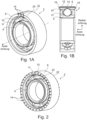
- FIGS 1A and 1B show a first embodiment of a ball bearing 2 according to the disclosure.
- the ball bearing 2 is a micro ball bearing and is intended in a surgical instrument 4 (not shown in Figures 1A and 1B ) to be used.
- the ball bearing 2 has an inner ring 6 and an outer ring 8. Between the inner ring 6 and the outer ring 8 rolling (rolling) bodies, in particular balls 10, are provided, which are held by a cage 11.
- rolling bearings such as cylindrical roller bearings, needle bearings, tapered roller bearings, barrel bearings, toroidal roller bearings, with or without a ball cage, etc. can also be included in the disclosure should.
- the outer ring 8 of the ball bearing is in this case made of a non-conductive, hard material, for example ceramic.
- Three bores 12 extending in the axial direction of the ball bearing 2 are provided in the outer ring 8 of the ball bearing 2.
- the bores 12 extend over an entire axial length of the ball bearing 2 and are therefore through bores.
- a diameter of the bores is preferably smaller than 0.2 mm, more preferably approximately in the range of 0.1 mm.
- the holes are made, for example, by microlaser drilling.
- Signal lines (signal strands) 14 are inserted into the holes 12 and extend over the entire axial length of the holes 12.
- the signal lines 14 are made of a highly conductive material, in particular copper, silver or gold.
- a diameter of the signal lines 14 corresponds approximately to a diameter of the bores and is therefore smaller than 0.2 mm, preferably in the range of 0.1 mm.
- the signal lines 14 are axially fixed in the bores 12. This axial fixation is realized in the present case by plastically changing axial ends 16 of the signal lines 14 deformed, in particular caulked. Then the signal lines 14 have a slightly enlarged diameter at their axial ends 16, as shown Fig. 1B emerges.
- the bores 12 can also first be metallized (before the signal lines 14 are inserted) and the axial fixation can take place via an adhesive connection or a solder connection.
- the (two) axial ends 16 of the signal lines 14 protrude beyond the outer ring 8 in the axial direction of the ball bearing 2, preferably by approximately 0.1 to 0.3 mm. This is so that the signal lines 14 can enter into a plug connection with another component of the surgical instrument 4, for example a sleeve 18.
- a ball bearing 2 is provided with signal lines 14 integrated into the ball bearing 2.
- the ball bearing can forward or transmit electrical signals from a first axial end 20 to a second axial end 22 of the ball bearing 2 (from proximal to distal and vice versa, or in the axial direction of the ball bearing 2) via the signal lines 14.
- the disclosure is not limited to this and one, two, four, five, six or more signal lines 14 can also be provided, which can be of any size the circumference of the outer ring 8 of the ball bearing 2 can be distributed.
- the entire outer ring 8 of the ball bearing 2' is utilized and provided with bores 12 and signal lines 14 (see Fig. 2 ).
- the holes 12 or signal lines 14 are evenly distributed over the outer ring 8 of the ball bearing 2 '.
- the diameter of the signal lines 14 is in Fig. 2 shown embodiment preferably approximately/rounded 0.1 mm.
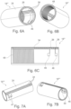
- Figures 3A, 3B, 3C and 3D show a sleeve 18 according to a first embodiment according to the disclosure.
- the sleeve 18 is preferably a spacer sleeve and is intended in a surgical instrument 4 (not shown in Fig. 3A to Fig. 3D ) to be used.
- the sleeve 18 is made of a non-conductive, hard material, for example ceramic.
- the sleeve 18 basically has an outer lateral surface 24, an inner lateral surface 26, a first axial end 28 and a second axial end 30.
- three straight/rectilinear grooves (channels) 32 are provided on the outer lateral surface 24 of the sleeve 18, which extend over an entire axial length of the sleeve 18.
- the grooves 32 are relatively fine or filigree and are produced by grinding or engraving, in particular laser engraving.
- Signal lines 34 are provided in the grooves 32, which also extend over the entire axial length of the sleeve 18.
- the signal lines (signal tracks) 34 are formed by first metallizing the grooves 32 and then coating them with a highly conductive material, in particular copper, silver or gold.
- the signal lines 34 on the outer surface 24 of the sleeve 18 are only provided in a lower region of the groove 32, as shown in particular Fig. 3D emerges, so that the outer surface 24 of the sleeve 18 is spaced from each signal line (signal path) 34 in the radial direction of the sleeve 18, in particular has a distance a.
- the disclosure is not limited to this and one, two, four, five, six or more signal lines 34 can also be provided, which can be arranged arbitrarily over the Outer surface 24 of the sleeve 18 can be distributed. It is also possible to utilize the entire outer surface 24 of the sleeve 18 and thus to distribute signal lines 34 (evenly) over the entire outer surface 24.
- Three straight/rectilinear signal lines (signal paths) 36 are provided on the inner surface 26 of the sleeve 18.
- the signal lines 36 on the inner surface 26 extend over an entire axial length of the sleeve 18 and are in the present case designed as metallized (signal) tracks.
- Each signal line 36 on the inner surface 26 of the sleeve 18 is presently provided in the circumferential direction of the sleeve 18 at the same location as a signal line 34 on the outer surface 24 of the sleeve 18.
- the signal lines 34 and the signal lines 36 run parallel and straight in the axial direction of the sleeve 18 and are provided at the same position in the circumferential direction of the sleeve 18.
- At least one signal line 36 on the inner surface 26 of the sleeve 18 is electrically conductively connected to a signal line 34 on the outer surface 24 of the sleeve 18.
- each signal line 36 can also be connected in an electrically conductive manner to a corresponding signal line 34.
- fine (micro) bores 38 are provided in the sleeve 18 between the groove 32/the signal line 34 on the outer lateral surface 24 and the signal line 36 on the inner lateral surface 26, which each extend in a radial direction of the sleeve 18.
- the holes 38 contain (good) conductive material, so that the signal lines 34 are electrically conductively connected to the signal lines 36 via the conductive material in the holes 38.
- the disclosure is not limited to this and one, two, four, five, six or more signal lines 36 can also be provided, which can be arranged arbitrarily over the Inner lateral surface 26 of the sleeve 18 can be distributed. It is also possible to utilize the entire inner surface 26 of the sleeve 18 and thus distribute signal lines 36 (evenly) over the entire inner surface 26.
- the sleeve 18 is a sleeve 18 which has integrated signal lines 34, 36.
- the signal lines 34 on the outer surface 24 of the sleeve 18 you can use the outer area of the sleeve 18 electrical signals are picked up, forwarded and transmitted.
- the signal lines 36 on the inner surface 26 of the sleeve 18 electrical signals can be picked up, forwarded and transmitted in an interior region of the sleeve 18.
- the sleeve 18 basically enables a forwarding or transmission of electrical signals both in the axial direction between the first axial end 28 of the sleeve 18 and the second axial end 30 of the sleeve 18 and in the radial direction of the sleeve 18 between the inner lateral surface 26 and the Outer lateral surface 24.
- the sleeve 18 is therefore set up for the multidirectional forwarding or transmission of electrical signals.
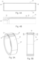
- Figures 4A and 4B show a sleeve 18 'according to the disclosure according to a second embodiment.
- the sleeve 18 'according to the second embodiment has a signal line/signal track 34 on the outer surface 24.
- the sleeve 18' is very thin-walled.
- the sleeve 18' is slightly thicker-walled only at the first axial end 28 of the sleeve 18' and at the second axial end 30 of the sleeve 18'.
- the groove 32 provided on the outer surface 24 has different depths.
- a depth of the groove 32 at the first axial end 28 and the second axial end 30 of the sleeve 18' is deeper/larger than in the remaining remaining (middle) region of the sleeve 18'.
- the signal line/signal path 34 is also inserted into the sleeve 18' at different depths (deeper at the axial ends 28, 30), so that an extremely thin-walled sleeve 18' is realized, particularly in the central region of the sleeve 18'.
- a signal line 34, 36 of the sleeve 18 according to the first embodiment according to the disclosure can be inserted into the sleeve 18 at different depths (corresponding to the second embodiment).
- the grooves 32 can also have different depths overall, that is to say a first groove 32 can be deeper than a second groove 32, so that accordingly a first Signal line 34 can be inserted deeper than a second signal line 34 into the sleeve 18/can run in the axial direction of the sleeve 18.
- Figures 5A and 5B show a sleeve 18" according to the disclosure according to a third embodiment.
- the sleeve 18" according to the third embodiment has three signal lines/signal tracks 34 on the outer surface 24.
- the comments on the sleeve 18 of the first embodiment are, in particular, that this ensures electrical separation of the signal lines 34 from one another. This is necessary because an outer tube 40 of a surgical instrument 4, into which the sleeve 18 is preferably to be inserted and on which the sleeve 18 rests directly, is often made of metal.
- an insulator 42 is arranged on each signal line 34 in the sleeve 18".
- the insulator 42 is an insert, in particular made of silicone.
- the insulator 42 can also be realized using an adhesive layer.
- the insulator 42 is arranged in the groove 32, is inserted into the groove 32 and is located on the signal line 34 or, in other words, radially further out with respect to the signal line 34.
- the insulator 42 extends over an entire axial length of the groove 32 or the signal line 34 and thus covers the signal line 34 completely.
- recesses 44 are provided on the first axial end 28 of the sleeve 18" and on the second axial end 30 of the sleeve 18" in the area in which the insulator 42 is applied to the signal line 34.
- the recesses 44 are provided in particular to enable a plug-in connection with the projecting axial ends 16 of the ball bearing 2, 2' (the signal contacts of the ball bearing 2, 2').
- the additional insulation provided by the insulator 42 makes the surgical instrument (milling handpiece) 4, into which the sleeve 18" is to be inserted, less sensitive to penetrating conductive liquids (e.g. a saline solution).
- penetrating conductive liquids e.g. a saline solution
- electrical contacts/contact surfaces 46 are provided on the inner lateral surface 26 of the sleeve 18'".
- the electrical contacts/contact surfaces 46 basically serve as contacts/contact surfaces for sensors or other (electronic) components.
- Each of the electrical contacts/contact surfaces 46 is electrically conductively connected to a respective signal line 36, that is to say a first electrical contact 46 of the two electrical contacts 46 is electrically conductively connected to a first signal line 36 of the three signal lines 36 and a second electrical contact 46 of the two electrical contacts 46 is electrically conductive to one second signal line 36 of the three signal lines 36 connected. How out Fig.
- the signal lines 36 which are connected to electrical contacts 46, are interrupted on the inner surface 26 of the sleeve 18′′′.
- These signal lines 36 which are interrupted here, are electrically conductively connected to signal lines 34 on the outer surface 24 by means of conductive material in the (micro) bores 38 (cf. first embodiment of the sleeve 18) and are accordingly continued on the outside of the sleeve 18′′′.
- a signal line 36 (the third signal line 36) provided on the inner surface 26 is electrically conductively connected to a readout antenna 48.
- the third signal line 36 is designed on the inner surface 26 in such a way that the third signal line 36 itself forms the readout antenna 48.
- the readout antenna 48 is preferably used for reading or writing to an RFID chip (not shown).
- the RFID chip can be used for Example may be provided in a tool (not shown) which is inserted into the surgical instrument (milling handpiece), for example a milling tool.
- the descriptions of the sleeve 18, 18′, 18′′ of the previous embodiments, in particular the description of the sleeve 18 of the first embodiment, are applicable.
- Figures 7A and 7B show a sleeve 18 ⁇ according to the disclosure according to a fifth embodiment.
- two electrical contacts/contact surfaces 47 are provided on the outer surface 24, each of which is electrically conductively connected to a signal line 34.
- electrical contacts/contact surfaces 47 which are provided on the outer lateral surface 24 (outside) are also conceivable.
- the external electrical contacts/contact surfaces 47 can be used to connect external (electronic) components, such as sensors or antennas.
- external (electronic) components such as sensors or antennas.
- electrical signals are transmitted to the outside (e.g. to the outer tube 40 of the surgical instrument 4) via the electrical contacts/contact surfaces 47 on the outer surface 24. This can be useful, for example, in a proximal area of the surgical instrument 4, in which the installation space of the surgical instrument 4 increases.
- signal lines 34, 36 which are on one side (for example a signal line 34 on the outside in Fig. 7A ) are interrupted, are continued by continuous signal lines 34, 36 on the opposite side (for example a signal line 36 on the inside). Also is in Fig. 7B It can be seen that according to the present fifth embodiment, preferably also inside/on the Inner lateral surface 26 an electrical contact 46/electrical contacts 46 is/are provided, to which a sensor 50 is attached.
- the descriptions of the sleeve 18, 18', 18", 18' of the previous embodiments, in particular the descriptions of the sleeve 18, 18' of the first and fourth embodiments, are applicable.
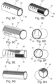
- the sleeve 18′′′ ⁇ is basically a multilayer sleeve and consists of a large number of sleeves or tubes placed one inside the other, i.e. arranged in several layers.
- three sleeves/tubes are placed one inside the other, namely an outer sleeve 52, which is in Figures 8C and 8D is shown, a middle sleeve 54, which in Figures 8E and 8F is shown, and an inner sleeve 56, which in Figures 8G and 8H is shown.
- the outer sleeve 52 has signal lines/signal tracks 34 and electrical contacts/contact surfaces 47 on the outside (on its outer surface).
- signal lines 34 and four electrical contacts 47 are provided here.
- Both the signal lines 34 and the electrical contacts 47 are connected/connectable to the inside (to the inner lateral surface of the sleeve 52) via micro-holes 38, which can contain conductive material.
- the micro-holes 38 which can connect the signal lines 34 to the inside, are in the present case only provided in a defined (certain) connection area 58.
- the middle sleeve 54 also has signal lines/signal tracks 34 and electrical contacts/contact surfaces 47 on the outside (on its outer surface).
- a readout antenna 48 is also provided on the outside.
- Two signal lines 34 of the six signal lines 34 provided are connected to the readout antenna 48.
- the remaining four signal lines are each connected to an electrical contact 47.
- the signal lines 34 and the electrical contacts 47 are connected/connectable to the inside (to the inner surface of the sleeve 54).
- the micro-holes, which connect the signal lines 34 to the inside are only provided in a defined (certain) connection area 58 and connect the external signal lines 34 to internal signal lines 36. Both the external signal lines 34 and the internal signal lines 36 extend on the middle one Sleeve 54 does not extend over the entire axial length of sleeve 54.
- the middle sleeve 54 is used in particular for a connection/connection/interconnection (of signal lines or electrical contacts) from the inside to the outside or from the outside to the inside (in the radial direction of the sleeve 18''). Furthermore, additional signal lines/signal tracks (conducting tracks) can be applied via the middle sleeve 54 (for example in antenna form to form the readout antenna 48).
- the inner sleeve 56 has signal lines/signal tracks 34 on the outside (on its outer surface). Inside (on its inner surface) it has signal lines/signal tracks 36.
- the external signal lines 34 extend over the entire axial length of the inner sleeve 56 and are therefore continuous.
- the inner sleeve 56 has two electrical contacts 46 on the inside, each of which is connected to a signal line 36. In order to realize the connection of the electrical contacts 46 to the signal lines 36, a signal line 36 is interrupted in the present case.
- a connection from the inner sleeve 56 to a signal line 34 (outside) of the inner sleeve 56 is then conceivable.
- a connection can also be made directly to the middle sleeve 54. From the middle sleeve 54, a connection can finally take place both to the outer sleeve 52 and back to the inner sleeve 56, in particular another signal line 34, 36 of the inner sleeve 56.
- all signal lines 36 can also be continuous, that is, extend over the entire axial length of the inner sleeve 52.
- the signal lines 34, 36 of the sleeves 52, 54, 56 are in alignment, i.e. arranged directly above or below one another, when the multilayer sleeve 18'' is mounted.
- the connection areas 58 provided on the outer sleeve 52 and the middle sleeve 54 are also arranged in congruence, i.e. directly above or below one another. The same applies to the contact surfaces 47 arranged on both the outer sleeve 52 and the middle sleeve 54.
- An electrical connection between the three sleeves 52, 54, 56 is realized via the micro-holes 38.
- a connection can be made at certain, defined points using solder or other metallic connection.
- even more functions can be integrated into the sleeve 18′′′ ⁇ according to the sixth embodiment and the available installation space is utilized to the maximum.
- Fig. 9A shows a sectional view of a surgical instrument 4 according to the disclosure.
- the surgical instrument 4 in the present case is preferably a surgical handpiece, more preferably a milling handpiece.
- the surgical instrument 4 basically has a distal region 60 and a proximal region 62.
- the proximal region 62 is characterized by the fact that the installation space in it increases.
- the outer tube 40 (a cylindrical, elongated tube) of the surgical instrument (milling handpiece) 4 is provided in the distal region 60.
- a coupling element 64 is arranged, which serves to hold a tool, for example a milling tool.
- electrical signals are to be transmitted from a distal end of the surgical instrument 4 to the proximal region 62 without the installation space increasing, that is to say without the outer diameter of the outer tube 40 becoming larger, for example. According to the disclosure, this is achieved when the ball bearings 2, 2' according to the disclosure and the sleeves 18, 18', 18", 18′′′, 18"", 18" according to the disclosure are arranged within the outer tube 40.
- a ball bearing 2 according to the disclosure is initially connected to the coupling element 64 at the distal tip.
- a sleeve according to the disclosure which can be designed, for example, like the sleeve 18 "(whereby the insulator 42 can also be omitted).
- a ball bearing 2 is provided, which in turn is followed by a sleeve according to the disclosure.
- This sleeve is similar to that Sleeve 18 (with additional electrical contacts 46) or similar to the sleeve 18′′′ (without readout antenna 48).
- a ball bearing 2, a sleeve 18" (with or without insulator 42), a ball bearing 2, a sleeve 18' , a ball bearing 2 and a sleeve 18.
- the protruding axial ends 16 of the signal lines 14 provided on the ball bearings 2, 2' are used for the electrical connection/connection between the ball bearings 2, 2' and the sleeve 18, 18', 18", 18", 18", 18". Plug connection with the sleeves 18, 18', 18", 18′′′, 18"", 18′′′ ⁇ .
- the axial ends 16 can be inserted into recesses 44 or into grooves 32.
- FIG. 9D which shows the arrangement of ball bearings 2, 2 'and sleeves 18, 18', 18", 18', 18'', 18'' (without outer tube 40), any number of ball bearings 2, 2' and Sleeves 18, 18', 18", 18′′′, 18"", 18′′′ ⁇ can be combined.
Landscapes
- Engineering & Computer Science (AREA)
- General Engineering & Computer Science (AREA)
- Health & Medical Sciences (AREA)
- Mechanical Engineering (AREA)
- Surgery (AREA)
- Life Sciences & Earth Sciences (AREA)
- Biomedical Technology (AREA)
- Molecular Biology (AREA)
- Orthopedic Medicine & Surgery (AREA)
- Oral & Maxillofacial Surgery (AREA)
- Dentistry (AREA)
- Heart & Thoracic Surgery (AREA)
- Medical Informatics (AREA)
- Nuclear Medicine, Radiotherapy & Molecular Imaging (AREA)
- Animal Behavior & Ethology (AREA)
- General Health & Medical Sciences (AREA)
- Public Health (AREA)
- Veterinary Medicine (AREA)
- Manufacturing & Machinery (AREA)
- Surgical Instruments (AREA)
- Mounting Of Bearings Or Others (AREA)
- Rolling Contact Bearings (AREA)
Claims (15)
- Instrument chirurgical (4), en particulier pièce à main de fraisage, avec : au moins un palier à roulement (2, 2'), en particulier un palier à billes, lequel est conçu pour la transmission ou le transfert de signaux électriques et présente à cet effet au moins une ligne de signalisation de palier à roulement (14) ou une voie de signalisation de palier à roulement intégrée dans le palier à roulement (2, 2').
- Instrument chirurgical (4) selon la revendication 1, caractérisé en ce qu'est prévue au moins une ligne de signal de palier à roulement (14), en particulier un toron de signal de palier à roulement, laquelle est insérée dans un alésage (12) prévu dans le palier à roulement (2, 2'), qui s'étend sur toute une longueur axiale du palier à roulement (2, 2'), et est de préférence fixée axialement.
- Instrument chirurgical (4) selon la revendication 2, caractérisé en ce que la ligne de signal de palier à roulement (14) fait saillie dans la direction axiale du palier à roulement (2, 2'), de sorte que la ligne de signal de palier à roulement (14) est agencée pour établir un contact ou une connexion enfichable avec un autre composant, en particulier avec une douille (18, 18', 18", 18‴, 18"", 18‴ʺ).
- Instrument chirurgical (4) selon l'une quelconque des revendications 1 à 3, comprenant en outre au moins une douille (18, 18', 18", 18‴, 18"", 18‴ʺ) qui est agencée pour la transmission ou le transfert de signaux électriques et qui présente à cet effet au moins une ligne de signal de douille (34, 36) ou une voie de signal de douille intégrée dans la douille (18, 18', 18", 18"", 18‴ʺ).
- Instrument chirurgical (4) selon la revendication 4, caractérisé en ce que la douille (18, 18', 18", 18‴, 18"", 18‴ʺ) est destinée à la transmission ou au transfert de signaux électriques dans une direction axiale entre une première extrémité axiale (28) et une seconde extrémité axiale (30) de la douille (18, 18', 18", 18‴, 18"", 18‴ʺ) et/ou dans une direction radiale entre une surface d'enveloppe intérieure (26) et une surface d'enveloppe extérieure (24) de la douille (18, 18', 18", 18‴, 18"", 18‴ʺ).
- Instrument chirurgical (4) selon la revendication 4 ou 5, caractérisé en ce qu'une surface d'enveloppe extérieure (24) de la douille (18, 18', 18", 18‴, 18"", 18‴ʺ) présente au moins une rainure (32) qui s'étend sur toute une longueur axiale de la douille (18, 18', 18", 18‴, 18"", 18‴ʺ), et la ligne de signal de douille (34) ou la voie de signal de douille est prévue dans la rainure (32).
- Instrument chirurgical (4) selon la revendication 6, caractérisé en ce que la ligne de signal de douille (34) ou la voie de signal de douille est décalée vers l'intérieur par rapport à la surface d'enveloppe extérieure (24) de la douille (18, 18', 18", 18‴, 18"", 18‴ʺ), de sorte que la ligne de signal de douille (34) ou la voie de signal de douille est située dans une portion inférieure de la rainure (32), dans lequel de préférence un isolant (42) est agencé au-dessus de la ligne de signal de douille (34) ou de la voie de signal de douille.
- Instrument chirurgical (4) selon l'une quelconque des revendications 4 à 7, caractérisé en ce qu'une surface d'enveloppe intérieure (26) du manchon (18, 18‴, 18"", 18‴ʺ) présente au moins une ligne de signal de douille (36) ou une voie de signal de douille.
- Instrument chirurgical (4) selon l'une quelconque des revendications 4 à 8, caractérisé en ce qu'une ligne de signal de douille (36) ou une voie de signal de douille prévue sur une surface d'enveloppe intérieure (26) de la douille (18, 18‴, 18"", 18‴ʺ) est reliée de manière électriquement conductrice à une ligne de signal de douille (36) ou à une voie de signal de douille prévue sur une surface d'enveloppe extérieure (24) de la douille (18, 18‴, 18"", 18‴ʺ).
- Instrument chirurgical (4) selon l'une quelconque des revendications 4 à 9, caractérisé en ce qu'un contact électrique (46, 47) et/ou une antenne de lecture (48) est/sont relié(s) de manière électriquement conductrice à la ligne de signal de douille (34, 36) ou à la voie de signal de douille.
- Instrument chirurgical (4) selon l'une quelconque des revendications 4 à 10, caractérisé en ce que la douille (18‴ʺ) est constituée d'une pluralité de douilles (52, 54, 56) emboîtées les unes dans les autres.
- Instrument chirurgical (4) selon l'une quelconque des revendications 4 à 11, caractérisé en ce que la douille (18, 18', 18", 18‴, 18"", 18‴ʺ) est réalisée comme suit :fabrication de la douille (18, 18', 18", 18‴, 18"", 18‴ʺ) à partir d'un matériau non conducteur ; etpréparation d'une ligne de signal (34, 36) ou d'une voie de signal conductrice sur une surface d'enveloppe extérieure (24) et/ou une surface d'enveloppe intérieure (26) de la douille par métallisation et éventuellement par revêtement avec un matériau conducteur.
- Instrument chirurgical (4) selon l'une quelconque des revendications 4 à 12, caractérisé en ce que le palier à roulement (2, 2') et la douille (18, 18', 18", 18"", 18‴ʺ) sont agencés de manière adjacente l'un à l'autre dans l'instrument chirurgical (4), de sorte que l'au moins une ligne de signal de palier à roulement (14) ou voie de signal de palier à roulement du palier à roulement (2, 2') est reliée à l'au moins une ligne de signal de douille (34, 36) ou voie de signal de douille de la douille (18, 18', 18", 18‴, 18"", 18‴ʺ) par le biais d'une connexion enfichable, de sorte que l'instrument chirurgical (4) est conçu pour la transmission de signaux ou le transfert de signaux entre le palier à roulement (2, 2') et la douille (18, 18', 18", 18"", 18"", 18‴ʺ).
- Procédé de fabrication d'un palier à roulement (2, 2'), en particulier d'un palier à roulement (2, 2') d'un instrument chirurgical (4) selon l'une quelconque des revendications 1 à 13, comprenant les étapes suivantes :préparation d'au moins un alésage (12) traversant s'étendant dans la direction axiale du palier à roulement (2, 2'), en particulier dans une bague extérieure (8) du palier à roulement, en particulier par micro-perçage au laser ;insertion d'une ligne de signal (14), en particulier d'un fil de signal, dans l'alésage (12) ; etpréparation d'une fixation axiale de la ligne de signal (14) dans l'alésage (12).
- Utilisation dans un instrument chirurgical (4) d'un palier à roulement (2, 2') qui est conçu pour la transmission ou le transfert de signaux électriques et qui présente à cet effet au moins une ligne de signal de palier à roulement (14) ou une voie de signal de palier à roulement intégrée dans le palier à roulement (2, 2').
Applications Claiming Priority (2)
| Application Number | Priority Date | Filing Date | Title |
|---|---|---|---|
| DE102020101171.7A DE102020101171A1 (de) | 2020-01-20 | 2020-01-20 | Signalweiterleitung bzw. -übertragung in einem chirurgischen Instrument |
| PCT/EP2021/051061 WO2021148400A1 (fr) | 2020-01-20 | 2021-01-19 | Transfert ou transmission de signal dans un instrument chirurgical |
Publications (2)
| Publication Number | Publication Date |
|---|---|
| EP4093982A1 EP4093982A1 (fr) | 2022-11-30 |
| EP4093982B1 true EP4093982B1 (fr) | 2023-12-20 |
Family
ID=74215910
Family Applications (1)
| Application Number | Title | Priority Date | Filing Date |
|---|---|---|---|
| EP21701438.0A Active EP4093982B1 (fr) | 2020-01-20 | 2021-01-19 | Transfert ou transmission de signal dans un instrument chirurgical |
Country Status (8)
| Country | Link |
|---|---|
| US (1) | US12390230B2 (fr) |
| EP (1) | EP4093982B1 (fr) |
| JP (1) | JP2023512632A (fr) |
| CN (1) | CN115280026A (fr) |
| BR (1) | BR112022014084A2 (fr) |
| DE (1) | DE102020101171A1 (fr) |
| ES (1) | ES2972497T3 (fr) |
| WO (1) | WO2021148400A1 (fr) |
Families Citing this family (1)
| Publication number | Priority date | Publication date | Assignee | Title |
|---|---|---|---|---|
| CN117167408B (zh) * | 2023-09-04 | 2026-03-27 | 二重(德阳)重型装备有限公司 | 齿轮箱内轴承用智能化轴承套 |
Citations (2)
| Publication number | Priority date | Publication date | Assignee | Title |
|---|---|---|---|---|
| US5830144A (en) * | 1995-03-28 | 1998-11-03 | Vesely; Ivan | Tracking data sheath |
| EP2589347B1 (fr) * | 2011-03-24 | 2015-09-09 | Olympus Medical Systems Corp. | Dispositif de préhension de traitement |
Family Cites Families (21)
| Publication number | Priority date | Publication date | Assignee | Title |
|---|---|---|---|---|
| JPH07127647A (ja) * | 1993-11-04 | 1995-05-16 | Nippon Seiko Kk | 回転支持装置 |
| US5868673A (en) | 1995-03-28 | 1999-02-09 | Sonometrics Corporation | System for carrying out surgery, biopsy and ablation of a tumor or other physical anomaly |
| SE9600408L (sv) * | 1996-02-05 | 1997-08-06 | Skf Ab | Rullningslager |
| DE19824022C2 (de) * | 1998-05-29 | 2003-10-30 | Skf Gmbh | Wälzlager mit Strombrücke |
| DE10017572B4 (de) * | 2000-04-10 | 2008-04-17 | INSTITUT FüR MIKROTECHNIK MAINZ GMBH | Wälzlager mit fernabfragbaren Erfassungseinheiten |
| DE102008016592A1 (de) | 2008-03-31 | 2009-10-01 | Bombardier Transportation Gmbh | Messlager |
| US20120116261A1 (en) | 2010-11-05 | 2012-05-10 | Mumaw Daniel J | Surgical instrument with slip ring assembly to power ultrasonic transducer |
| WO2012151493A2 (fr) | 2011-05-04 | 2012-11-08 | The University Of Akron | Stimulateur à fréquence variable pour électrochirurgie |
| DE102011050193A1 (de) | 2011-05-06 | 2012-11-08 | Aesculap Ag | Chirurgisches Instrument, chirurgisches Handstück und chirurgisches Antriebssystem |
| US8734476B2 (en) | 2011-10-13 | 2014-05-27 | Ethicon Endo-Surgery, Inc. | Coupling for slip ring assembly and ultrasonic transducer in surgical instrument |
| WO2014116782A1 (fr) * | 2013-01-23 | 2014-07-31 | Cambridge Surgical Instruments, Inc. | Dispositif pour fournir un renvoi d'informations sensorielles lors d'interventions chirurgicales |
| CN103054624B (zh) * | 2013-01-28 | 2014-11-19 | 青岛理工大学 | 外科手术颅骨磨削温度在线检测及可控手持式磨削装置 |
| DE102013214703A1 (de) | 2013-07-29 | 2015-01-29 | Zf Friedrichshafen Ag | Wälzlager für ein Getriebe |
| US9839425B2 (en) * | 2014-06-26 | 2017-12-12 | Covidien Lp | Adapter assembly for interconnecting electromechanical surgical devices and surgical loading units, and surgical systems thereof |
| EP3026277B1 (fr) | 2014-11-27 | 2023-04-26 | Skf Magnetic Mechatronics | Palier magnétique, appareil comprenant un tel palier magnétique et procédé de fabrication dudit palier |
| CN204394449U (zh) * | 2015-01-11 | 2015-06-17 | 复旦大学 | 一种用于在体显微成像及多通道电信号同步记录的套管 |
| DE102015007593B4 (de) * | 2015-06-16 | 2019-04-04 | Audi Ag | Radlager für ein Fahrzeug, insbesondere für ein Kraftfahrzeug |
| JP2017219099A (ja) | 2016-06-07 | 2017-12-14 | 株式会社ジェイテクト | 転がり軸受装置 |
| US10381871B2 (en) * | 2016-06-29 | 2019-08-13 | Wisconsin Alumni Research Foundation | High power transfer through load-supporting bearings |
| DE102017117004B4 (de) | 2017-07-27 | 2021-08-12 | Ims Connector Systems Gmbh | Koaxialer Steckverbinder |
| CN110645266B (zh) * | 2019-06-26 | 2020-11-27 | 扬州市舜意机械有限公司 | 一种传感一体化的关节轴承及其使用方法 |
-
2020
- 2020-01-20 DE DE102020101171.7A patent/DE102020101171A1/de active Pending
-
2021
- 2021-01-19 ES ES21701438T patent/ES2972497T3/es active Active
- 2021-01-19 JP JP2022543772A patent/JP2023512632A/ja active Pending
- 2021-01-19 US US17/793,607 patent/US12390230B2/en active Active
- 2021-01-19 EP EP21701438.0A patent/EP4093982B1/fr active Active
- 2021-01-19 BR BR112022014084A patent/BR112022014084A2/pt unknown
- 2021-01-19 CN CN202180009916.1A patent/CN115280026A/zh active Pending
- 2021-01-19 WO PCT/EP2021/051061 patent/WO2021148400A1/fr not_active Ceased
Patent Citations (2)
| Publication number | Priority date | Publication date | Assignee | Title |
|---|---|---|---|---|
| US5830144A (en) * | 1995-03-28 | 1998-11-03 | Vesely; Ivan | Tracking data sheath |
| EP2589347B1 (fr) * | 2011-03-24 | 2015-09-09 | Olympus Medical Systems Corp. | Dispositif de préhension de traitement |
Also Published As
| Publication number | Publication date |
|---|---|
| BR112022014084A2 (pt) | 2022-09-13 |
| EP4093982A1 (fr) | 2022-11-30 |
| CN115280026A (zh) | 2022-11-01 |
| US20230062637A1 (en) | 2023-03-02 |
| US12390230B2 (en) | 2025-08-19 |
| DE102020101171A1 (de) | 2021-07-22 |
| ES2972497T3 (es) | 2024-06-13 |
| JP2023512632A (ja) | 2023-03-28 |
| WO2021148400A1 (fr) | 2021-07-29 |
Similar Documents
| Publication | Publication Date | Title |
|---|---|---|
| DE69700120T2 (de) | Federkontaktelement | |
| DE19781697B4 (de) | Elektrisch leitfähige Kontakteinheit | |
| DE60109499T2 (de) | Verfahren und vorrichtung zum zurückhalten einer federtastspitze | |
| DE102007054592B4 (de) | Steckverbindungsvorrichtung, ausgebildet zur Verbindung zweier Funktionselemente zur Signal- und Leistungsübertragung | |
| DE19707490A1 (de) | HF-Koaxial-Steckverbinder | |
| EP3593412B1 (fr) | Élément de conducteur intérieur et procédé de production d'un système | |
| EP3627636B1 (fr) | Connecteur enfichable électrique, raccord de modules et ensemble de carte de circuits imprimés | |
| EP3979436A1 (fr) | Connecteur enfichable électrique, agencement de carte de circuit imprimé et procédé de montage d'un agencement de carte de circuit imprimé | |
| WO2010018098A1 (fr) | Capteur inductif de conductivité | |
| EP4093982B1 (fr) | Transfert ou transmission de signal dans un instrument chirurgical | |
| DE102005023977B4 (de) | Vorrichtung und Verfahren zum Herstellen einer Vorrichtung | |
| EP3482465B1 (fr) | Élément de contact à conducteur interne, sollicité par un ressort | |
| DE60000853T2 (de) | Verbinder mit überbrückbaren und konfigurierbaren Kontakten | |
| DE4125018A1 (de) | Elektrische verbindung, insbesondere durchkontaktierung bei einer leiterplatte | |
| DE69330436T2 (de) | Dielektrische Filteranordnung | |
| EP4185219B1 (fr) | Instrument médical doté d'un roulement à billes ou d'un palier lisse comme générateur | |
| DE102017202329A1 (de) | Multilayer-Leiterplatte sowie elektronische Anordnung mit einer solchen | |
| DE102007005559B4 (de) | Führungsdraht mit elektrischem Funktionselement | |
| DE102014107241A1 (de) | Kontakthülse, elektronikbaugruppe und verfahren zur herstellung einer elektronikbaugruppe | |
| EP3439115A1 (fr) | Connecteur à fiches électrique | |
| DE102018105857A1 (de) | Vorrichtung zum Messen von Strom und Verfahren zur Herstellung | |
| DE3243690C2 (de) | Kontaktvorrichtung für eine Energieversorgungsanlage | |
| DE102018109306B4 (de) | Verfahren zur Herstellung einer elektrischen Heizvorrichtung | |
| DE10328285A1 (de) | Leiterplatte | |
| DE102020111040B3 (de) | Werkzeugspannvorrichtung |
Legal Events
| Date | Code | Title | Description |
|---|---|---|---|
| STAA | Information on the status of an ep patent application or granted ep patent |
Free format text: STATUS: UNKNOWN |
|
| STAA | Information on the status of an ep patent application or granted ep patent |
Free format text: STATUS: THE INTERNATIONAL PUBLICATION HAS BEEN MADE |
|
| PUAI | Public reference made under article 153(3) epc to a published international application that has entered the european phase |
Free format text: ORIGINAL CODE: 0009012 |
|
| STAA | Information on the status of an ep patent application or granted ep patent |
Free format text: STATUS: REQUEST FOR EXAMINATION WAS MADE |
|
| 17P | Request for examination filed |
Effective date: 20220809 |
|
| AK | Designated contracting states |
Kind code of ref document: A1 Designated state(s): AL AT BE BG CH CY CZ DE DK EE ES FI FR GB GR HR HU IE IS IT LI LT LU LV MC MK MT NL NO PL PT RO RS SE SI SK SM TR |
|
| DAV | Request for validation of the european patent (deleted) | ||
| DAX | Request for extension of the european patent (deleted) | ||
| GRAP | Despatch of communication of intention to grant a patent |
Free format text: ORIGINAL CODE: EPIDOSNIGR1 |
|
| STAA | Information on the status of an ep patent application or granted ep patent |
Free format text: STATUS: GRANT OF PATENT IS INTENDED |
|
| INTG | Intention to grant announced |
Effective date: 20230718 |
|
| GRAS | Grant fee paid |
Free format text: ORIGINAL CODE: EPIDOSNIGR3 |
|
| GRAA | (expected) grant |
Free format text: ORIGINAL CODE: 0009210 |
|
| STAA | Information on the status of an ep patent application or granted ep patent |
Free format text: STATUS: THE PATENT HAS BEEN GRANTED |
|
| AK | Designated contracting states |
Kind code of ref document: B1 Designated state(s): AL AT BE BG CH CY CZ DE DK EE ES FI FR GB GR HR HU IE IS IT LI LT LU LV MC MK MT NL NO PL PT RO RS SE SI SK SM TR |
|
| REG | Reference to a national code |
Ref country code: GB Ref legal event code: FG4D Free format text: NOT ENGLISH |
|
| REG | Reference to a national code |
Ref country code: CH Ref legal event code: EP |
|
| REG | Reference to a national code |
Ref country code: DE Ref legal event code: R096 Ref document number: 502021002220 Country of ref document: DE |
|
| REG | Reference to a national code |
Ref country code: IE Ref legal event code: FG4D Free format text: LANGUAGE OF EP DOCUMENT: GERMAN |
|
| P01 | Opt-out of the competence of the unified patent court (upc) registered |
Effective date: 20240103 |
|
| PG25 | Lapsed in a contracting state [announced via postgrant information from national office to epo] |
Ref country code: GR Free format text: LAPSE BECAUSE OF FAILURE TO SUBMIT A TRANSLATION OF THE DESCRIPTION OR TO PAY THE FEE WITHIN THE PRESCRIBED TIME-LIMIT Effective date: 20240321 |
|
| REG | Reference to a national code |
Ref country code: LT Ref legal event code: MG9D |
|
| PG25 | Lapsed in a contracting state [announced via postgrant information from national office to epo] |
Ref country code: LT Free format text: LAPSE BECAUSE OF FAILURE TO SUBMIT A TRANSLATION OF THE DESCRIPTION OR TO PAY THE FEE WITHIN THE PRESCRIBED TIME-LIMIT Effective date: 20231220 |
|
| REG | Reference to a national code |
Ref country code: NL Ref legal event code: MP Effective date: 20231220 |
|
| PG25 | Lapsed in a contracting state [announced via postgrant information from national office to epo] |
Ref country code: LT Free format text: LAPSE BECAUSE OF FAILURE TO SUBMIT A TRANSLATION OF THE DESCRIPTION OR TO PAY THE FEE WITHIN THE PRESCRIBED TIME-LIMIT Effective date: 20231220 Ref country code: GR Free format text: LAPSE BECAUSE OF FAILURE TO SUBMIT A TRANSLATION OF THE DESCRIPTION OR TO PAY THE FEE WITHIN THE PRESCRIBED TIME-LIMIT Effective date: 20240321 Ref country code: FI Free format text: LAPSE BECAUSE OF FAILURE TO SUBMIT A TRANSLATION OF THE DESCRIPTION OR TO PAY THE FEE WITHIN THE PRESCRIBED TIME-LIMIT Effective date: 20231220 Ref country code: BG Free format text: LAPSE BECAUSE OF FAILURE TO SUBMIT A TRANSLATION OF THE DESCRIPTION OR TO PAY THE FEE WITHIN THE PRESCRIBED TIME-LIMIT Effective date: 20240320 |
|
| PG25 | Lapsed in a contracting state [announced via postgrant information from national office to epo] |
Ref country code: NL Free format text: LAPSE BECAUSE OF FAILURE TO SUBMIT A TRANSLATION OF THE DESCRIPTION OR TO PAY THE FEE WITHIN THE PRESCRIBED TIME-LIMIT Effective date: 20231220 |
|
| PG25 | Lapsed in a contracting state [announced via postgrant information from national office to epo] |
Ref country code: SE Free format text: LAPSE BECAUSE OF FAILURE TO SUBMIT A TRANSLATION OF THE DESCRIPTION OR TO PAY THE FEE WITHIN THE PRESCRIBED TIME-LIMIT Effective date: 20231220 Ref country code: RS Free format text: LAPSE BECAUSE OF FAILURE TO SUBMIT A TRANSLATION OF THE DESCRIPTION OR TO PAY THE FEE WITHIN THE PRESCRIBED TIME-LIMIT Effective date: 20231220 Ref country code: NO Free format text: LAPSE BECAUSE OF FAILURE TO SUBMIT A TRANSLATION OF THE DESCRIPTION OR TO PAY THE FEE WITHIN THE PRESCRIBED TIME-LIMIT Effective date: 20240320 Ref country code: NL Free format text: LAPSE BECAUSE OF FAILURE TO SUBMIT A TRANSLATION OF THE DESCRIPTION OR TO PAY THE FEE WITHIN THE PRESCRIBED TIME-LIMIT Effective date: 20231220 Ref country code: LV Free format text: LAPSE BECAUSE OF FAILURE TO SUBMIT A TRANSLATION OF THE DESCRIPTION OR TO PAY THE FEE WITHIN THE PRESCRIBED TIME-LIMIT Effective date: 20231220 Ref country code: HR Free format text: LAPSE BECAUSE OF FAILURE TO SUBMIT A TRANSLATION OF THE DESCRIPTION OR TO PAY THE FEE WITHIN THE PRESCRIBED TIME-LIMIT Effective date: 20231220 |
|
| REG | Reference to a national code |
Ref country code: ES Ref legal event code: FG2A Ref document number: 2972497 Country of ref document: ES Kind code of ref document: T3 Effective date: 20240613 |
|
| PG25 | Lapsed in a contracting state [announced via postgrant information from national office to epo] |
Ref country code: IS Free format text: LAPSE BECAUSE OF FAILURE TO SUBMIT A TRANSLATION OF THE DESCRIPTION OR TO PAY THE FEE WITHIN THE PRESCRIBED TIME-LIMIT Effective date: 20240420 |
|
| PG25 | Lapsed in a contracting state [announced via postgrant information from national office to epo] |
Ref country code: CZ Free format text: LAPSE BECAUSE OF FAILURE TO SUBMIT A TRANSLATION OF THE DESCRIPTION OR TO PAY THE FEE WITHIN THE PRESCRIBED TIME-LIMIT Effective date: 20231220 |
|
| PG25 | Lapsed in a contracting state [announced via postgrant information from national office to epo] |
Ref country code: SK Free format text: LAPSE BECAUSE OF FAILURE TO SUBMIT A TRANSLATION OF THE DESCRIPTION OR TO PAY THE FEE WITHIN THE PRESCRIBED TIME-LIMIT Effective date: 20231220 |
|
| PG25 | Lapsed in a contracting state [announced via postgrant information from national office to epo] |
Ref country code: SM Free format text: LAPSE BECAUSE OF FAILURE TO SUBMIT A TRANSLATION OF THE DESCRIPTION OR TO PAY THE FEE WITHIN THE PRESCRIBED TIME-LIMIT Effective date: 20231220 Ref country code: SK Free format text: LAPSE BECAUSE OF FAILURE TO SUBMIT A TRANSLATION OF THE DESCRIPTION OR TO PAY THE FEE WITHIN THE PRESCRIBED TIME-LIMIT Effective date: 20231220 Ref country code: RO Free format text: LAPSE BECAUSE OF FAILURE TO SUBMIT A TRANSLATION OF THE DESCRIPTION OR TO PAY THE FEE WITHIN THE PRESCRIBED TIME-LIMIT Effective date: 20231220 Ref country code: IS Free format text: LAPSE BECAUSE OF FAILURE TO SUBMIT A TRANSLATION OF THE DESCRIPTION OR TO PAY THE FEE WITHIN THE PRESCRIBED TIME-LIMIT Effective date: 20240420 Ref country code: EE Free format text: LAPSE BECAUSE OF FAILURE TO SUBMIT A TRANSLATION OF THE DESCRIPTION OR TO PAY THE FEE WITHIN THE PRESCRIBED TIME-LIMIT Effective date: 20231220 Ref country code: CZ Free format text: LAPSE BECAUSE OF FAILURE TO SUBMIT A TRANSLATION OF THE DESCRIPTION OR TO PAY THE FEE WITHIN THE PRESCRIBED TIME-LIMIT Effective date: 20231220 |
|
| PG25 | Lapsed in a contracting state [announced via postgrant information from national office to epo] |
Ref country code: PL Free format text: LAPSE BECAUSE OF FAILURE TO SUBMIT A TRANSLATION OF THE DESCRIPTION OR TO PAY THE FEE WITHIN THE PRESCRIBED TIME-LIMIT Effective date: 20231220 Ref country code: PT Free format text: LAPSE BECAUSE OF FAILURE TO SUBMIT A TRANSLATION OF THE DESCRIPTION OR TO PAY THE FEE WITHIN THE PRESCRIBED TIME-LIMIT Effective date: 20240422 |
|
| PG25 | Lapsed in a contracting state [announced via postgrant information from national office to epo] |
Ref country code: PT Free format text: LAPSE BECAUSE OF FAILURE TO SUBMIT A TRANSLATION OF THE DESCRIPTION OR TO PAY THE FEE WITHIN THE PRESCRIBED TIME-LIMIT Effective date: 20240422 Ref country code: PL Free format text: LAPSE BECAUSE OF FAILURE TO SUBMIT A TRANSLATION OF THE DESCRIPTION OR TO PAY THE FEE WITHIN THE PRESCRIBED TIME-LIMIT Effective date: 20231220 |
|
| REG | Reference to a national code |
Ref country code: CH Ref legal event code: PL |
|
| PG25 | Lapsed in a contracting state [announced via postgrant information from national office to epo] |
Ref country code: LU Free format text: LAPSE BECAUSE OF NON-PAYMENT OF DUE FEES Effective date: 20240119 |
|
| REG | Reference to a national code |
Ref country code: DE Ref legal event code: R097 Ref document number: 502021002220 Country of ref document: DE |
|
| PG25 | Lapsed in a contracting state [announced via postgrant information from national office to epo] |
Ref country code: LU Free format text: LAPSE BECAUSE OF NON-PAYMENT OF DUE FEES Effective date: 20240119 Ref country code: MC Free format text: LAPSE BECAUSE OF FAILURE TO SUBMIT A TRANSLATION OF THE DESCRIPTION OR TO PAY THE FEE WITHIN THE PRESCRIBED TIME-LIMIT Effective date: 20231220 |
|
| PG25 | Lapsed in a contracting state [announced via postgrant information from national office to epo] |
Ref country code: DK Free format text: LAPSE BECAUSE OF FAILURE TO SUBMIT A TRANSLATION OF THE DESCRIPTION OR TO PAY THE FEE WITHIN THE PRESCRIBED TIME-LIMIT Effective date: 20231220 |
|
| PG25 | Lapsed in a contracting state [announced via postgrant information from national office to epo] |
Ref country code: BE Free format text: LAPSE BECAUSE OF NON-PAYMENT OF DUE FEES Effective date: 20240131 |
|
| PG25 | Lapsed in a contracting state [announced via postgrant information from national office to epo] |
Ref country code: CH Free format text: LAPSE BECAUSE OF NON-PAYMENT OF DUE FEES Effective date: 20240131 |
|
| PLBE | No opposition filed within time limit |
Free format text: ORIGINAL CODE: 0009261 |
|
| STAA | Information on the status of an ep patent application or granted ep patent |
Free format text: STATUS: NO OPPOSITION FILED WITHIN TIME LIMIT |
|
| PG25 | Lapsed in a contracting state [announced via postgrant information from national office to epo] |
Ref country code: SI Free format text: LAPSE BECAUSE OF FAILURE TO SUBMIT A TRANSLATION OF THE DESCRIPTION OR TO PAY THE FEE WITHIN THE PRESCRIBED TIME-LIMIT Effective date: 20231220 |
|
| PG25 | Lapsed in a contracting state [announced via postgrant information from national office to epo] |
Ref country code: SI Free format text: LAPSE BECAUSE OF FAILURE TO SUBMIT A TRANSLATION OF THE DESCRIPTION OR TO PAY THE FEE WITHIN THE PRESCRIBED TIME-LIMIT Effective date: 20231220 Ref country code: DK Free format text: LAPSE BECAUSE OF FAILURE TO SUBMIT A TRANSLATION OF THE DESCRIPTION OR TO PAY THE FEE WITHIN THE PRESCRIBED TIME-LIMIT Effective date: 20231220 Ref country code: CH Free format text: LAPSE BECAUSE OF NON-PAYMENT OF DUE FEES Effective date: 20240131 Ref country code: BE Free format text: LAPSE BECAUSE OF NON-PAYMENT OF DUE FEES Effective date: 20240131 |
|
| REG | Reference to a national code |
Ref country code: BE Ref legal event code: MM Effective date: 20240131 |
|
| 26N | No opposition filed |
Effective date: 20240923 |
|
| PG25 | Lapsed in a contracting state [announced via postgrant information from national office to epo] |
Ref country code: IE Free format text: LAPSE BECAUSE OF NON-PAYMENT OF DUE FEES Effective date: 20240119 |
|
| PG25 | Lapsed in a contracting state [announced via postgrant information from national office to epo] |
Ref country code: IE Free format text: LAPSE BECAUSE OF NON-PAYMENT OF DUE FEES Effective date: 20240119 |
|
| PGFP | Annual fee paid to national office [announced via postgrant information from national office to epo] |
Ref country code: AT Payment date: 20250417 Year of fee payment: 5 |
|
| PG25 | Lapsed in a contracting state [announced via postgrant information from national office to epo] |
Ref country code: CY Free format text: LAPSE BECAUSE OF FAILURE TO SUBMIT A TRANSLATION OF THE DESCRIPTION OR TO PAY THE FEE WITHIN THE PRESCRIBED TIME-LIMIT; INVALID AB INITIO Effective date: 20210119 |
|
| PG25 | Lapsed in a contracting state [announced via postgrant information from national office to epo] |
Ref country code: HU Free format text: LAPSE BECAUSE OF FAILURE TO SUBMIT A TRANSLATION OF THE DESCRIPTION OR TO PAY THE FEE WITHIN THE PRESCRIBED TIME-LIMIT; INVALID AB INITIO Effective date: 20210119 |
|
| PG25 | Lapsed in a contracting state [announced via postgrant information from national office to epo] |
Ref country code: TR Free format text: LAPSE BECAUSE OF FAILURE TO SUBMIT A TRANSLATION OF THE DESCRIPTION OR TO PAY THE FEE WITHIN THE PRESCRIBED TIME-LIMIT Effective date: 20231220 |
|
| PGFP | Annual fee paid to national office [announced via postgrant information from national office to epo] |
Ref country code: GB Payment date: 20260122 Year of fee payment: 6 |
|
| PGFP | Annual fee paid to national office [announced via postgrant information from national office to epo] |
Ref country code: ES Payment date: 20260217 Year of fee payment: 6 |
|
| PGFP | Annual fee paid to national office [announced via postgrant information from national office to epo] |
Ref country code: DE Payment date: 20260120 Year of fee payment: 6 |
|
| PGFP | Annual fee paid to national office [announced via postgrant information from national office to epo] |
Ref country code: IT Payment date: 20260130 Year of fee payment: 6 |
|
| PGFP | Annual fee paid to national office [announced via postgrant information from national office to epo] |
Ref country code: FR Payment date: 20260127 Year of fee payment: 6 |