EP4094191B1 - Jeton à bande ultra-large - Google Patents
Jeton à bande ultra-large Download PDFInfo
- Publication number
- EP4094191B1 EP4094191B1 EP21700934.9A EP21700934A EP4094191B1 EP 4094191 B1 EP4094191 B1 EP 4094191B1 EP 21700934 A EP21700934 A EP 21700934A EP 4094191 B1 EP4094191 B1 EP 4094191B1
- Authority
- EP
- European Patent Office
- Prior art keywords
- uwb
- token
- data
- sensor data
- sensors
- Prior art date
- Legal status (The legal status is an assumption and is not a legal conclusion. Google has not performed a legal analysis and makes no representation as to the accuracy of the status listed.)
- Active
Links
Images




Classifications
-
- G—PHYSICS
- G06—COMPUTING OR CALCULATING; COUNTING
- G06K—GRAPHICAL DATA READING; PRESENTATION OF DATA; RECORD CARRIERS; HANDLING RECORD CARRIERS
- G06K19/00—Record carriers for use with machines and with at least a part designed to carry digital markings
- G06K19/06—Record carriers for use with machines and with at least a part designed to carry digital markings characterised by the kind of the digital marking, e.g. shape, nature, code
- G06K19/067—Record carriers with conductive marks, printed circuits or semiconductor circuit elements, e.g. credit or identity cards also with resonating or responding marks without active components
- G06K19/0672—Record carriers with conductive marks, printed circuits or semiconductor circuit elements, e.g. credit or identity cards also with resonating or responding marks without active components with resonating marks
-
- G—PHYSICS
- G06—COMPUTING OR CALCULATING; COUNTING
- G06K—GRAPHICAL DATA READING; PRESENTATION OF DATA; RECORD CARRIERS; HANDLING RECORD CARRIERS
- G06K19/00—Record carriers for use with machines and with at least a part designed to carry digital markings
- G06K19/06—Record carriers for use with machines and with at least a part designed to carry digital markings characterised by the kind of the digital marking, e.g. shape, nature, code
- G06K19/067—Record carriers with conductive marks, printed circuits or semiconductor circuit elements, e.g. credit or identity cards also with resonating or responding marks without active components
- G06K19/07—Record carriers with conductive marks, printed circuits or semiconductor circuit elements, e.g. credit or identity cards also with resonating or responding marks without active components with integrated circuit chips
- G06K19/0701—Record carriers with conductive marks, printed circuits or semiconductor circuit elements, e.g. credit or identity cards also with resonating or responding marks without active components with integrated circuit chips at least one of the integrated circuit chips comprising an arrangement for power management
- G06K19/0707—Record carriers with conductive marks, printed circuits or semiconductor circuit elements, e.g. credit or identity cards also with resonating or responding marks without active components with integrated circuit chips at least one of the integrated circuit chips comprising an arrangement for power management the arrangement being capable of collecting energy from external energy sources, e.g. thermocouples, vibration, electromagnetic radiation
-
- G—PHYSICS
- G06—COMPUTING OR CALCULATING; COUNTING
- G06K—GRAPHICAL DATA READING; PRESENTATION OF DATA; RECORD CARRIERS; HANDLING RECORD CARRIERS
- G06K7/00—Methods or arrangements for sensing record carriers, e.g. for reading patterns
- G06K7/10—Methods or arrangements for sensing record carriers, e.g. for reading patterns by electromagnetic radiation, e.g. optical sensing; by corpuscular radiation
- G06K7/10009—Methods or arrangements for sensing record carriers, e.g. for reading patterns by electromagnetic radiation, e.g. optical sensing; by corpuscular radiation sensing by radiation using wavelengths larger than 0.1 mm, e.g. radio-waves or microwaves
Definitions
- the invention relates to a UWB token, a UWB monitoring system and a method for controlling a UWB monitoring system.
- Access cards or key cards are used, for example, to monitor access to buildings.
- Individual access cards or key cards can be distinguished using card IDs and/or cryptographic keys assigned to the cards. Since such card IDs, like cryptographic keys, are pure data values, they can be transferred to another card (once they are known).
- Clones resulting from such a data copying process can be used for deception and/or manipulation purposes.
- US 2014/354414 A1 describes a method for reading an RFID tag comprising receiving a signal from the tag comprising a structural mode and an antenna mode, and selectively analyzing a time period of the received signal corresponding to the antenna mode.
- RFID radio frequency identification
- CN 105 956 645 A describes an electronic tag without a chip that uses a double-sided dielectric substrate.
- the electronic tag includes an upper conductive pattern layer, a middle dielectric layer, and a lower conductive ground.
- the conductive pattern layer is composed of six rectangular complementary open resonant microstrip loops having different sizes and a characteristic 50-ohm impedance signal transmission microstrip line.
- the six rectangular complementary open resonant microstrip loops of different sizes form a 6-bit coding resonant circuit on a dielectric plate.
- Different code combinations can be realized by changing the size of the different rectangular complementary open resonant microstrip loops, adjusting the resonant frequency of the corresponding rectangular complementary open resonant microstrip loops, and increasing or removing the rectangular complementary open resonant microstrip loops.
- the invention is based on the object of creating a token with an improved identity assignment.
- Embodiments include a UWB token comprising a UWB antenna for transmitting and receiving UWB signals.
- the UWB antenna comprises a plurality of conductive antenna structures.
- the antenna structures have a geometric coding with an individual resonance pattern identifying the UWB token.
- Embodiments may have the advantage that the UWB token can be identified based on its resonance pattern identifiable, which is a hardware feature. Such a hardware feature makes it difficult to simply clone the UWB token by copying identification data.
- a UWB communication channel is established between the UWB token and one or more UWB communication devices, e.g. UWB sensors.
- UWB signals from the UWB token are received by the UWB communication devices. These signals can be measured and the underlying resonance pattern referenced in order to identify the UWB token based on individual resonance patterns of the antenna structures. For example, one or more reference resonance patterns are provided. The determined resonance pattern of the UWB token is compared with the one or more reference resonance patterns.
- the determined resonance pattern is identified as the corresponding reference resonance pattern and the UWB token is identified as a UWB token to which or whose token ID the reference resonance pattern is assigned.
- the antenna structures for the UWB token are individually coordinated with one another so that the electromagnetic waves transmitted by the antenna structures overlap and have an individual resonance pattern that identifies the UWB token.
- cloning requires a considerable amount of testing. or dismantling the UWB token to be cloned.
- hardware features allow the corresponding data to be easily read out. In particular, phishing attacks are not possible, in which the user is asked for identification data under false pretenses. In addition, it is much more difficult and time-consuming to gain direct physical access to the UWB token than to request identification data, for example digitally. Access to the hardware features would only be possible, for example, if the user hands over the UWB token or if it is stolen.
- the conductive antenna structures comprise strip-shaped and/or planar antenna elements.
- Embodiments can have the advantage that a large number of different resonance patterns can be realized through the geometric design of the strip-shaped and/or planar antenna elements, which can be used to individualize a large number of UWB tokens.
- the antenna structures comprise a plurality of coordinated individual antennas which form a patch antenna.
- Embodiments can have the advantage that a patch antenna can be designed to be particularly space-saving and flat and is, for example, well suited for integration on circuit boards.
- the patch antenna can, for example, consist of metal surfaces, such as rectangular metal surfaces, the long side of which corresponds to a length of ⁇ /2. The metal surface thus acts as a resonator, similar to dipole antennas.
- a patch antenna can have a directional effect.
- the patch antenna can be combined with a reflector, such as in the form of a metal surface, to amplify the signal.
- the reflector is arranged, for example, behind the patch antenna.
- the individual antennas can be designed, for example, as a loop for inductive antenna coupling, as a surface for capacitive antenna coupling and/or as an antenna stub, omnidirectional antenna, wire, etc. for antenna coupling using an E-field.
- UWB Ultra Wideband
- UWB refers to a wireless transmission of electromagnetic pulse-shaped signals over a number of parallel radio channels with low transmission power, e.g. up to a maximum of 1 mW.
- frequency ranges with a bandwidth of at least 500 MHz and/or of at least 20% of the arithmetic mean of the lower and upper limit frequencies of the frequency band used are used.
- UWB is based on generating pulses with the shortest possible pulse duration, which is why the spectrum emitted or received via the UWB antenna is larger or wider the shorter the pulse duration, according to the laws of Fourier transformation.
- the product of the temporal and spectral width of the pulse is constant.
- the total transmission power of a few milliwatts or less is distributed over such a large frequency range that no interference is to be expected for the radio operation of narrowband transmission methods. It is therefore difficult or impossible to detect that a transmission is taking place using UWB.
- a UWB signal appears more like noise. This enables communication that is difficult to locate and can be used in the same frequency range as conventional transmission methods.
- UWB does not use a fixed carrier frequency that is modulated. Instead, data transmission is based on pulse phase modulation or pulse position modulation ("Pulse-Position Modulation"/PPM) using a number of individual pulses. Another option for data transmission using UWB is to modulate the polarity and/or amplitude of the pulses. If the timing of the individual pulses differs sufficiently, several UWB transmission channels can be operated in the same spatial area without mutual interference.
- Pulse-Position Modulation Pulse-Position Modulation
- UWB systems can provide useful bit rates up to the Gbit/s range.
- the range of UWB transmissions can be in the range of a few meters up to a hundred meters.
- UWB technology also enables the implementation of a radar method using UWB radar sensors.
- an alternating electromagnetic field with a wide bandwidth and small field strengths is generated. Depending on the nature of objects in the propagation range of the alternating electromagnetic field, this will deform the alternating field.
- the resulting field can be detected by a UWB sensor. If both the initial field and the resulting field are known, the cause of the detected deformation and thus the type and geometry of the object(s) in the propagation range of the alternating electromagnetic field can be determined.
- UWB radar sensors for example, operate at frequencies between 30 MHz and 12.4 GHz. Depending on the application, resolutions of centimeters down to a few millimeters can be achieved with working bandwidths of 5 GHz.
- short pulses are sent out and compared with the pulse patterns reflected by the object(s). This allows geometrical dimensions such as distance, thickness, length, position, body shape, movement and/or speed to be determined. Objects can also be detected through clothing and walls. The properties of the propagation medium for the electromagnetic fields are assumed to be known.
- UWB can prevent tracking of mobile devices because devices communicating via UWB, such as UWB tokens, cannot be located without knowledge of the UWB coding used. Furthermore, the relatively short range of UWB ensures that tracking and/or eavesdropping from a distance can be effectively prevented.
- UWB coding offers independent, instantaneous encryption of the transmitted data, which is thus protected against eavesdropping.
- UWB has a high resistance to interference signals ("jamming") due to the wide frequency band. Due to these special technical properties, which are advantageous for security applications, a monitoring system can be implemented using UWB that can guarantee a high level of protection of the processes as well as the sensor data contained therein or used, but especially in connection with personal sensor data of those involved. In particular, a high level of data transmission security can be ensured using UWB.
- a UWB token is understood to be a hardware token in the form of a mobile, portable electronic device that is configured for wireless communication using UWB.
- a UWB token can also be configured to determine position data based on a time-of-flight measurement and triangulation of UWB signals that it receives from localization sensors of the UWB monitoring system.
- the UWB token can be designed as a document or integrated into a document, in particular a valuable or security document.
- a "document” is understood to mean paper-based and/or plastic-based documents, such as electronic identification documents, in particular passports, identity cards, visas and driving licenses, vehicle registration documents, vehicle registration documents, company IDs, health cards or other ID documents as well as chip cards, means of payment, in particular banknotes, bank cards and credit cards, waybills or other proof of authorization.
- electronic identification documents in particular passports, identity cards, visas and driving licenses
- vehicle registration documents vehicle registration documents
- company IDs company IDs
- health cards or other ID documents as well as chip cards
- means of payment in particular banknotes, bank cards and credit cards, waybills or other proof of authorization.
- one or more attributes of a user or object associated with the document are stored in the memory of such a document.
- a UWB sensor is understood to be a sensor or anchor that is configured to transmit recorded data, e.g. sensor data, using UWB.
- a UWB sensor such as a UWB radar sensor or a UWB localization sensor, can be configured to capture sensor data using UWB.
- a UWB sensor can be configured to capture the sensor data using a UWB-independent method, such as an optical, acoustic, chemical, thermal, electromagnetic and/or vibration-based method.
- the UWB sensors are configured for data transmission exclusively using UWB.
- one or more of the UWB sensors can additionally be configured to transmit recorded data using a wired data connection.
- some of the UWB sensors of the UWB monitoring system are configured to transmit recorded data using a wired data connection.
- all of the UWB sensors of the UWB monitoring system are configured to transmit sensed data via a wired data connection.
- Sensor data is understood to mean data acquired by one of the UWB sensors, i.e., for example, optical, acoustic, chemical, thermal, electromagnetic and/or vibration-based data.
- the sensor data is transmitted by the sensing UWB sensors within the UWB monitoring system using UWB.
- one or more of the UWB sensors can additionally be configured to transmit acquired data using a wired data connection.
- the sensor data can also be data acquired by the UWB sensors using UWB.
- the sensor data is sensor data from a UWB radar sensor or a UWB localization sensor.
- the UWB token comprises a band that is configured to carry the UWB token.
- Embodiments can have the advantage that a user can wear the UWB token comfortably on their body, for example around their neck or wrist, using the band.
- the UWB token can be attached to a piece of clothing, an accessory, a bag or a wallet using the band and carried by the user.
- Embodiments can have the advantage that the use of a band not only allows the UWB token to be worn securely, but can also be set in motion as the user moves, in particular in pendulum movements, which can be used both for generating energy and for authenticating the user.
- the UWB antenna is at least partially integrated into the band and at least a part of the conductive antenna structures extend along the band, i.e. a longitudinal direction or extension direction of the band.
- Embodiments can have the advantage that the antenna structure can be integrated into the band.
- the entire UWB token can be integrated into the band.
- the UWB token can be designed compactly and the antenna structure can be partially or completely integrated into the band.
- Embodiments can have the advantage that the band offers sufficient space for a UWB antenna with conductive antenna structures that have an individual geometric design. The more space is available, the more geometric design options open up.
- the band comprises one or more sensors.
- the sensors can, for example, comprise a motion sensor and/or sensors for detecting vital functions of a wearer of the band, such as pulse and/or breathing.
- a motion sensor for detecting vital functions of a wearer of the band, such as pulse and/or breathing.
- the sensors it can be determined, for example, whether the UWB token is being worn and/or the wearer of the UWB token can be authenticated, for example using a movement pattern of the UWB token detected by the sensors when worn by the wearer, a pulse pattern of the wearer detected by the sensors and/or a breathing pattern of the wearer detected by the sensors.
- the band comprises a display device, which for example comprises a display and/or one or more LEDs.
- the display device can for example display a result of an authentication, e.g. its success, using the one or more sensors.
- the display device can for example display a charging status of an energy storage module, e.g. an accumulator, and/or an energy generation status of an energy generation module of the UWB token.
- UWB for example, works in the range 3 to 9 GHz.
- a UWB antenna can therefore be designed to be correspondingly small. If a user is equipped with a band, such as a collar or bracelet, a number of conductive antenna structures can be applied to the band.
- the UWB token comprises an energy harvesting module configured to harvest electrical energy for operation of the UWB token by converting kinetic energy into electrical energy.
- the converted kinetic energy comprises, for example, kinetic energy from pendulum movement of the band when the UWB token is worn by a user.
- Embodiments may have the advantage that a pendulum movement caused by wearing the UWB token can be used to Energy generation can be used. This makes it possible to provide an autonomous energy supply for the UWB token.
- the UWB token further comprises an energy storage element for storing the electrical energy generated, such as a battery or accumulator.
- the energy storage element can also be configured for charging or pre-charging with electrical energy using an external energy source, for example wirelessly inductively or via a power cable.
- an external energy source for example wirelessly inductively or via a power cable.
- Embodiments can have the advantage that it can be ensured that the UWB token has sufficient electrical energy available for operation even after a longer rest period and/or initially before it is put on by the user.
- the UWB token is located on the user by means of a band to be worn, the UWB token naturally oscillates when worn, so that elements of the UWB token can convert kinetic energy of the pendulum movement to generate energy and/or record movement data of the pendulum movement to authenticate the user.
- the converted kinetic energy comprises, for example, kinetic energy from pulling on the band or unrolling the band and/or rolling up the band.
- part of the band is rolled up on a rolling device or a rolling device with a rolled-up tension band is arranged on the band.
- the rolling device comprises a rolling mechanism for rerolling the unrolled band or tension band.
- the rolling mechanism is, for example, spring-driven, whereby a spring is tensioned during unrolling and the spring force stored in the spring when the spring is subsequently relaxed is converted into a mechanical force for rolling up the band or tension band.
- the energy harvesting module is configured to convert the kinetic energy into the electrical energy using an electromagnetic, piezoelectric and/or electrostatic method.
- Embodiments may have the advantage of providing efficient harvesting of electrical energy from pendulum movements of the UWB token.
- Kinetic energy may occur when carrying the UWB token, for example in the form of vibrations of the UWB token, random displacements of the UWB token and/or forces acting on the UWB token.
- Such kinetic energy may be converted into electrical energy, for example, using electromagnetic, piezoelectric and/or electrostatic mechanisms.
- the UWB token provides an inertial frame in which a movably mounted, for example spring-loaded, inertial mass is arranged. Movements or vibrations of the inertial frame are transferred to the inertial mass, thereby generating a relative displacement between the inertial frame and the inertial mass. Furthermore, strains can occur.
- a resonance frequency which can, for example, be designed to correspond to the frequencies of the typical vibrations that occur when the UWB token is worn.
- the UWB token can, for example, be configured for a plurality of resonance frequencies and/or for a large frequency bandwidth.
- the conversion mechanism for converting the kinetic energy into mechanical energy can, for example, exploit mechanical strains and/or relative displacements within the system.
- a strain effect exploits a deformation and uses, for example, an active material, such as a piezoelectric material, to generate electrical energy from the strain.
- an active material such as a piezoelectric material
- Velocity is usually associated with electromagnetic energy conversion, while position is associated with electrostatic energy conversion.
- Piezoelectric conversion makes use of the piezoelectric effect, which occurs when certain materials subjected to mechanical stress are electrically polarized. Conversely, these materials deform when exposed to an electric field.
- Piezoelectric materials are known in many different forms and include, for example, single crystals such as quartz, piezoceramics such as lead zirconate titanate (PZT), thin films such as sputtered zinc oxide, screen-printable thick films based on piezoceramic powders or polymer materials such as polyvinylidene fluoride (PVDF).
- Piezoelectric materials generally have anisotropic properties, i.e. the properties of the material differ depending on the direction of force and orientation of the polarization and electrodes.
- Electromagnetic conversion uses electromagnetic induction, in which an electric current is generated in a conductor that is within a magnetic field.
- the conductor can, for example, be in the form of a coil. Electric current is generated in the conductor, for example, by a movement of the conductor in the magnetic field or by a change in the magnetic field.
- An electrostatic conversion uses relative motion between dielectrically isolated electrodes that form a capacitor. The electrodes are charged. Work against the electrostatic force between the electrodes results in harvested electrical energy.
- the UWB token comprises a motion sensor for detecting movement data of the band when the user wears the UWB token.
- the movement data of the band comprises data from pendulum movements of the band.
- the UWB token further comprises an authentication module for behavior-based authentication of the user wearing the UWB token using the detected movement data.
- the UWB token includes a motion sensor for capturing movement data of the band when the user wears the UWB token.
- the movement data of the band includes data of the pendulum movements of the band when worn.
- the UWB token also includes an authentication module for behavior-based authentication of the user wearing the UWB token using the captured movement data.
- Embodiments can have the advantage that movements of the UWB token resulting from the movements of the user who carries the UWB token can be recorded using the motion sensor. Since this motion data describes or quantifies movements of the UWB token that are based on movements of the user that are characteristic of the user, the recorded motion data is also characteristic of the user and can be used to authenticate the user. Recorded motion data is data from movements of the UWB token that are caused by the user carrying the UWB token with them, for example wearing it on their body. The characteristic movements of the user cause the UWB token to move in a manner that is characteristic of the user. This is the case even if the user does not actively interact with the UWB token, e.g. does not use a user interface of the UWB token, such as a button, a keyboard, a touchscreen, a microphone.
- a user interface of the UWB token such as a button, a keyboard, a touchscreen, a microphone.
- the motion sensor can, for example, comprise an acceleration sensor.
- a movement can, for example, be calculated by integrating acceleration measurements recorded by the acceleration sensor.
- the motion sensor can, for example, also detect its position in space and/or changes in position.
- the motion sensor comprises a gyroscope.
- the movement data recorded by the motion sensor is, for example, acceleration, inclination and/or position data.
- Embodiments can have the advantage that the user can be authenticated simply by carrying the UWB token. This can ensure that the mobile, portable UWB token is actually carried by the assigned user. This can prevent a user from separating from their UWB token for deceptive purposes, i.e., for example, swapping it, leaving it lying around or giving it to another person. In particular, if central processing and/or storage of personal data is to be avoided, monitoring the position of UWB tokens enables the whereabouts of the assigned users to be monitored without the user's personal data having to be centrally processed and/or stored.
- the test criterion can include, for example, that there is a sufficiently high level of agreement between the recorded movement data and one or more reference values stored for the registered user.
- the test criterion can also include that the recorded movement data and/or the one or more reference values used do not exceed a maximum age.
- the user is registered as a user of the UWB token during a learning phase.
- the learning phase includes recording the user's movement data by an authentication sensor in the form of a motion sensor the UWB token and extracting one or more reference values characteristic of the user to be registered.
- recorded movement data can be used in the event of successful authentication of the user to adapt and/or improve the reference values stored for the corresponding user.
- the reference values are stored in a memory of the UWB token.
- Embodiments can have the advantage that the reference values are only stored locally on the UWB token and thus remain under the control of the assigned user.
- the reference values are stored in a protected memory area of the memory of the mobile, portable UWB token.
- a "protected memory area” is understood here to be an area of an electronic memory to which access, for example read access or write access, is only possible via a processor coupled to the memory.
- the processor coupled to the memory enables access to the protected memory area, for example, only if a condition required for this is met.
- This condition can be, for example, a cryptographic condition, in particular successful authentication and/or successful authorization check.
- access is restricted to certain cryptographic programs and/or service applications.
- the reference values are stored in encrypted form in the memory of the UWB token.
- the encrypted reference values are decrypted to validate the captured authentication data.
- the captured authentication data is encrypted to validate using the encrypted reference values.
- Embodiments may have the advantage that the classification results can be pre-stored and are immediately available in the event of an authentication request. For example, the steps of capturing the movement data, entering the movement data and generating the classification result are repeated continuously, at fixed time intervals or randomly. For example, a repetition takes place in short time intervals of seconds, e.g. 10, 20, 30, 40, 50 seconds, or minutes, e.g. 1, 2, 3, 4, 5, 10, 15, 20, 25, 30 minutes.
- the authentication is used to monitor the presence of the UWB token on the associated user.
- the authentication request is received, for example, by a UWB monitoring system.
- the authentication signal is sent, for example, to the UWB monitoring system in response to the authentication request.
- the sending takes place using UWB.
- the UWB monitoring system can be configured to determine a position of the UWB token within a spatial area monitored by the UWB monitoring system.
- the position of the UWB token can be identified as the position of the user associated with the UWB token.
- Embodiments can have the advantage that the position of the user associated with the UWB token can be reliably determined via the UWB token in the event of successful validation.
- an authentication request is sent to the UWB token at predefined fixed intervals, at random intervals, randomly, upon detection of an exceptional event, upon reaching certain positions within the spatial area by the UWB token, upon detection of unusual behavior by the user of the UWB token.
- an authentication request is sent depending on the position of the UWB token within the spatial area.
- the spatial area can be divided into a plurality of spatial sections to which different security levels are assigned. If the position of the UWB token is, for example, in a spatial section with a higher security level, more authentications can be imitated than in a spatial section with a lower security level.
- Increasing the number of authentications can be implemented, for example, by shortening the intervals between sending authentication requests, increasing the probability of randomly sending authentication requests and/or shortening the distances between positions within the spatial area at which an authentication request is sent by the UWB token.
- a movement pattern of the UWB token can be determined, for example. If this movement pattern has any abnormalities, an authentication request can be sent.
- the movement patterns of a plurality of UWB tokens can be used as input data for a movement pattern classification module with a machine learning algorithm. For this training data, it can be specified that these are normal movement patterns without any abnormalities. If movement patterns are entered into the movement pattern classification module trained in this way as input data, the movement pattern classification module recognizes if there are any abnormalities compared to training movement patterns. As an output, the trained movement pattern classification module outputs, for example, a binary classification result: there are no abnormalities or there is one abnormality. For example, if the classification result indicates the presence of anomalies, an authentication request is sent; if the classification result indicates no anomalies, for example, no authentication request is sent.
- additional sensors i.e. additional sensors
- This bioinformation can include, for example, data on the user's body temperature, pulse, blood pressure or breathing. This is particularly possible if the UWB token or band is worn on the user's skin, for example on the neck or wrist or around the neck or wrist.
- This bioinformation can be used to check whether the UWB token is actually being worn by a user.
- this bioinformation can also be used to authenticate the user.
- the bioinformation includes vein data to authenticate the user based on the user's individual properties of their veins.
- the band comprises a holding element which is configured to hold an object.
- the UWB token can be used not only for localization and identification purposes, but also for other practical applications by the user.
- the UWB token is a lanyard.
- the holding element is a snap hook, fastening ring, or carrying case.
- a snap hook refers to a hook with a spring-supported snap closure for opening and closing the hook.
- the one or more objects are, for example, a document, a key, a mobile portable communication device such as a smartphone, a neck pouch.
- the strap is a lanyard that is configured to carry the UWB token around the user's neck.
- Embodiments can have the advantage that when worn around the user's neck, the user's hands remain free, that the UWB token can be worn on the user's skin and/or that pendulum movements can be particularly pronounced.
- the UWB token is integrated into a document.
- the document such as a valuable or security document, can be a paper-based and/or plastic-based document.
- the document can be designed, for example, as an electronic identification document, in particular passports, identity cards, visas, driving licenses, vehicle registration documents, vehicle registration documents, company IDs, health cards or other ID documents as well as chip cards, means of payment, in particular banknotes, bank cards and credit cards, waybills or other proof of authorization.
- the document can be configured to be worn around the user's neck using a neck strap or lanyard.
- the UWB token designed as a document can use pendulum movements, as described above, to authenticate the user and/or to generate energy, even if no antenna structures are integrated in the neck strap or lanyard itself, but only in the UWB token.
- the document has the shape of a chip card, for example in the ID-1 format according to ISO 7816, i.e. 85.60 mm by 53.98 mm.
- the UWB token is integrated into a mobile portable communication device.
- the mobile portable communication device is, for example, a smart device, such as a smartphone, a smartwatch, smart glasses, a phablet, a tablet, a smartband, a smart keychain, a smart card, etc.
- Embodiments may have the advantage of providing a UWB monitoring system that is able to identify UWB tokens based on individual resonance patterns. Since the identification is based on hardware properties of the UWB token, a high degree of certainty can be achieved that an identified UWB token is actually the corresponding UWB token and not a clone.
- the UWB monitoring system comprises the at least one UWB token that it is able to identify if the UWB token is within the spatial area.
- the UWB monitoring system comprises a plurality of UWB tokens that it is able to identify if the UWB tokens are within the spatial area.
- the UWB token further comprises sensors that can detect vital functions, such as breathing and/or pulse, of a wearer of the UWB token. Using the corresponding sensors, an individual breathing and/or pulse pattern of the wearer can thus be determined. The determined breathing and/or pulse pattern can be compared with the reference patterns of a plurality of breathing and/or pulse resonance patterns. In the event that a match between the determined individual breathing and/or pulse pattern and one of the reference patterns exceeds a predefined threshold, identifying the person associated with the corresponding reference pattern as the wearer of the transmitting UWB token. This identification method can be used based on any type of vital function and a pattern of the vital function determined for this vital function.
- vital functions such as breathing and/or pulse
- the spatial area is, for example, a spatial area with restricted access, such as a security area with restricted access.
- the spatial area with restricted access is, for example, demarcated from the surroundings and can only be accessed via one or more entrances or exits.
- the spatial area with restricted access is an indoor area or interior area.
- the plurality of UWB sensors comprises a plurality of UWB identification sensors, which are further configured to determine position data of the UWB token within the spatial area. Determining the position data comprises time-of-flight measurements of UWB signals between the UWB localization sensors and the UWB token.
- Embodiments may have the advantage that the UWB localization sensors can efficiently determine the position of the UWB token.
- UWB tokens are localized, for example, by means of triangulation using at least two or three localization sensors in the form of UWB antennas.
- the triangulation signals can be sent from the UWB token and/or from the UWB antennas.
- the triangulation signals can be evaluated by the UWB token and/or the UWB antennas and/or an evaluation module of the monitoring system.
- the UWB sensors are configured to detect relative positions and movements of multiple UWB tokens that a wearer wears. Based on the detected relative positions and movements of the UWB tokens, a motion triangulation of movements of the UWB tokens as a result of being worn by the wearer and thus of movements of the wearer itself can be carried out. Based on the movements detected in this way, it can be determined, for example, whether the UWB tokens are actually being worn by a wearer, whether they are being worn by the same wearer, i.e. jointly by a wearer, the wearer can be authenticated, for example, and/or abnormalities in the wearer's movements can be determined. Corresponding abnormalities can, for example, indicate an exceptional event.
- Embodiments can have the advantage that it can be ensured that personal sensor data, insofar as it is recorded by the UWB sensors, is not made available as a result of anonymization or is only made available in such a form that no conclusions can be drawn about the identity of the persons to whom the personal data relates.
- anonymization includes in particular changing personal sensor data in such a way that individual details about personal or factual circumstances can no longer be assigned to a specific or identifiable natural person or can only be assigned with a disproportionately large amount of time, cost and labor. Changing includes, for example, redesigning the content of recorded personal sensor data up to and including deleting it.
- Deleting refers, for example, to making personal sensor data unrecognizable up to and including completely removing the corresponding personal sensor data from a storage device for storing recorded sensor data.
- the storage device can, for example, be a local or central storage device of the UWB monitoring system.
- the authentication data is personal sensor data.
- Personal sensor data refers to sensor data that enables the identification of a person or can be assigned to a person to whom the personal sensor data relates.
- personal sensor data is, for example, individual information about the personal or factual circumstances of a specific or identifiable natural person, recorded using one of the UWB sensors.
- the personal sensor data includes visual sensor data, such as video and/or photo data, which can be used to recognize a person. This is particularly the case if a person's face can be recognized using the video and/or photo data.
- An anonymization filter is configured to selectively anonymize personal data.
- the anonymization filter can be configured to anonymize sensor data that is collected by certain UWB sensors or a certain type of UWB sensors of the UWB monitoring system. This is For example, video and/or image data which are recorded using a surveillance camera and on which individual persons can be identified.
- An exceptional event refers to an anomaly in the recorded sensor data, i.e. a data constellation that is not to be expected under predefined operating conditions.
- the anomaly can be an emergency situation, such as a fire or unauthorized entry into and/or movement within the spatial area.
- the exception event includes an unsuccessful attempt to identify the UWB token.
- Embodiments may have the advantage that in the case of a UWB token unknown to the UWB monitoring system, suspending the anonymization can determine what type of UWB token it is and/or who is actually carrying the UWB token.
- an exception event includes unsuccessful authentication.
- Unsuccessful authentication indicates that a UWB token is not being carried by the user assigned to it. For example, the assigned user is trying to move within the spatial area without the UWB token or the UWB token is being carried by an unassigned user who has thus gained or wants to gain unauthorized access to the spatial area.
- Unsuccessful authentication indicates that a UWB token is not being carried by the user assigned to it. For example, the assigned user is trying to move within the spatial area without the UWB token or the UWB token is being carried by an unassigned user who has thus gained or wants to gain unauthorized access to the spatial area.
- By suspending anonymization it can be recorded who is actually carrying the UWB token and/or where the assigned user is located.
- the suspension of anonymization is limited to personal sensor data that is recorded by UWB sensors that have a predefined reference to the detected exceptional event.
- a predefined reference consists in that the UWB sensors for whose personal sensor data anonymization is suspended are assigned to the same spatial section of the spatial area as the UWB sensor(s) in whose recorded sensor data the exceptional event is detected.
- Embodiments can have the advantage that the suspension of anonymization is limited not only in time but also in space. Thus, an unnecessary suspension of anonymization, e.g. for personal data that has nothing to do with the exceptional event, can be avoided.
- the predefined reference additionally or alternatively consists in that UWB sensors for whose personal sensor data anonymization is suspended are assigned to a predefined spatial section of the spatial area.
- the relevant spatial sections are, for example, entrances and exits to a restricted area.
- a possible unauthorized In the event of a breach into the restricted area or in the event of a possible emergency, such as a fire alarm, it may be advantageous to record who enters and/or leaves the restricted area or who attempts to enter and/or leave the restricted area.
- the anonymization of all personal sensor data acquired by the UWB monitoring system is suspended for a limited period of time.
- Embodiments may have the advantage of ensuring that no personal sensor data relevant and/or necessary for handling and/or resolving the exceptional event is missing due to the anonymization.
- anonymization by the anonymization filter includes deleting at least part of the personal sensor data.
- the temporary suspension of anonymization includes storing the personal sensor data that is recorded within a limited time window.
- Embodiments may have the advantage that in the event of deletion, i.e. complete removal of personal sensor data from local and/or central storage of the UWB monitoring system, it can be ensured that no one can gain access to this data.
- personal sensor data such as video and/or image data
- the stored data are made available for the purpose of data analysis, in particular for the purpose of identifying persons to whom the stored personal sensor data relates.
- the storage is temporary.
- the stored personal sensor data is deleted after it has been evaluated and/or when the exceptional situation ends.
- the storage is permanent.
- the limited time window begins with the detection of the exceptional event. According to embodiments, the limited time window ends with the expiration of a predetermined period of time or an end of the detection of the exceptional event.
- Embodiments can have the advantage that the storage of the personal sensor data is limited to a time window that is related to the detected exceptional event. It can be assumed, for example, that only personal sensor data recorded in this time window are relevant in the context of the detected exceptional event. According to embodiments, the limited time window ends, for example, when the exceptional event is no longer detected or can no longer be detected. In the case of a possible fire as an exceptional event, the exceptional event can be detected, for example, in the form of smoke being detected by a UWB sensor of the monitoring system designed as a smoke detector. If the exceptional event is no longer detected, i.e. no more smoke is detected, the suspension of anonymization is ended, for example.
- the suspension of anonymization is ended. Otherwise, the suspension is repeated or continued for the predetermined period of time.
- Further requirements include, for example, logging a confirmation in the UWB monitoring system that the exception event has been checked and no further measures are necessary or that all necessary measures have been taken.
- the further requirements can include, for example, logging a confirmation in the UWB monitoring system that the suspension of anonymization is not and/or no longer necessary.
- the predetermined period of time can, for example, be seconds and/or minutes long.
- the personal sensor data is deleted by the UWB sensor that records the personal sensor data to be deleted.
- the storage of the personal sensor data comprises a transfer of the personal sensor data by the UWB sensor that records the personal sensor data to be stored at least partially and/or completely by means of UWB to a storage module of the UWB monitoring system.
- the storage of the personal sensor data comprises a transfer of the personal sensor data by the UWB sensor that records the personal sensor data to be stored at least partially and/or completely by means of a wired data connection to a storage module of the UWB monitoring system.
- Embodiments may have the advantage that, in the case of direct deletion by the detecting UWB sensor, it can be ensured that the personal sensor data to be deleted within the monitoring system does not pass through the detecting UWB sensor. This effectively prevents anyone from gaining unauthorized access to the personal sensor data.
- Embodiments can also have the advantage that the personal sensor data stored in the memory module can be used to handle and/or resolve the exceptional event if necessary. For example, the stored personal sensor data can be analyzed to determine which people are and/or could be involved in the exceptional event.
- the memory module can be a local memory module of a plurality of memory modules distributed decentrally across the UWB monitoring system or a central memory module of the UWB monitoring system.
- anonymization by the anonymization filter comprises encrypting at least part of the personal sensor data.
- the temporary suspension of anonymization comprises a temporary provision of the corresponding personal sensor data in unencrypted form.
- Embodiments can have the advantage that access to the personal sensor data can be effectively prevented by encrypting the personal sensor data.
- access to personal sensor data that has already been recorded can be made possible by decryption.
- the personal sensor data is only made available in decrypted form for a limited time.
- the encryption of the personal sensor data is carried out by the UWB sensor that records the personal sensor data to be encrypted.
- Embodiments may have the advantage that the personal sensor data are encrypted directly when they are recorded and are only processed further in encrypted form by the UWB monitoring system. Encryption can be carried out, for example, with a public cryptographic key of an asymmetric key pair, so that it can be decrypted by an owner of the associated secret cryptographic key of the corresponding asymmetric key pair.
- the corresponding owner is, for example, a central or decentralized control module of the UWB monitoring system.
- the secret cryptographic keys are stored, for example, in a protected memory area of a memory module, which is assigned to the corresponding control module.
- the control module provides all UWB sensors or at least all of them used to record personal sensor data are provided with a uniform public cryptographic key for encryption.
- the control module provides all UWB sensors or at least all UWB sensors configured to capture personal sensor data with an individual public cryptographic key for encryption assigned to the corresponding UWB sensor.
- the control module provides the UWB sensors or at least the UWB sensors configured to capture personal sensor data with an individual uniform public cryptographic key for encryption assigned to the corresponding group.
- the groups can be divided in such a way that they each comprise UWB sensors which are assigned to the same spatial section of the spatial area, which are the same type of UWB sensor or which are configured to capture the same type of personal sensor data.
- providing the personal sensor data in unencrypted form includes suspending the encryption of the personal sensor data that is recorded within a limited time window.
- Embodiments can have the advantage that the effort required to decrypt the corresponding personal sensor data can be avoided and that this personal sensor data also remains unencrypted.
- providing the personal sensor data in unencrypted form includes decrypting encrypted personal sensor data that is recorded within the limited time window.
- Embodiments can have the advantage that the personal sensor data is only stored in encrypted form even in the event of an exceptional event. Providing the personal sensor data in unencrypted form can thus be effectively limited in time.
- the limited time window begins a predetermined period of time before the detection of the exceptional event or with the detection of the exceptional event. According to embodiments, the limited time window ends with the expiration of a predetermined period of time after the detection of the exceptional event or with an end of the detection of the exceptional event.
- Embodiments may have the advantage that the provision of the personal sensor data in unencrypted form is limited to a time window that is related to the detected exceptional event. It can be assumed, for example, that only personal sensor data recorded in this time window are relevant in the context of the detected exceptional event. According to embodiments, the limited time window ends, for example, when the exceptional event is no longer detected or can no longer be detected. In the case of a possible fire as an exceptional event, the exceptional event can be detected, for example, in the form of smoke being detected by a UWB sensor of the monitoring system designed as a smoke detector. If the exceptional event is no longer detected, i.e. no more smoke is detected, the suspension of encryption is ended, for example.
- the suspension of encryption is ended. Otherwise, the suspension is repeated or continued for the predetermined period of time.
- Other requirements include, for example, logging a confirmation in the UWB monitoring system that the exceptional event has been checked and that no further measures are necessary or that all necessary measures have been taken.
- the further requirements can include, for example, logging a confirmation in the UWB monitoring system that the suspension of encryption is not and/or no longer necessary.
- the predetermined time period can, for example, have a length of seconds and/or minutes. Starting the limited time window a predetermined time period before the exceptional event is detected can have the advantage that relevant personal sensor data that was recorded prior to the exceptional event can also be provided in unencrypted form.
- Embodiments can have the advantage that recorded sensor data, in particular personal sensor data, are only made available to authorized persons. Sensor data, such as position data and/or other data, is released, for example, according to an authorization profile of the requester. This allows an effective data protection layer to be integrated into the UWB monitoring system. Proof of authorization can be provided, for example, in the form of an authorization certificate.
- the request is received and checked, for example, by a decentralized or central control module of the UWB monitoring system. In the case of a successful check, the release is also carried out by the corresponding control module.
- the requested sensor data is stored in Response to the request is sent to the sender of the request or displayed on a display device of the UWB monitoring system. The transmission of the requested sensor data takes place, for example, in encrypted form, in particular it can take place using end-to-end encryption.
- the collected sensor data are divided into categories and checking the credential includes checking whether the credential entitles access to sensor data of the category to which the requested sensor data is assigned.
- Embodiments may have the advantage of allowing permissions to be granted on a category-by-category basis, so that credentials can be restricted to one or more of the categories.
- the collected personal sensor data are divided into categories and the suspension of anonymization occurs selectively only for one or more selected categories, for example depending on the type of exceptional event detected.
- the access authorization of the credential is extended for a limited period of time upon detection of the exceptional event.
- An extension of the credential means that with a given credential, more categories may be viewed in the event of detection of an exceptional event than if no exceptional event is detected.
- the scope of the extension depends on the type of exceptional event detected.
- the access authorization for all valid credentials for access to at least one category of sensor data is extended for a limited period of time to all categories of sensor data in the event of detection of an exceptional event.
- Embodiments can have the advantage that, for example, depending on the sensitivity of the sensor data, different authorization credentials are required to access the corresponding sensor data, and thus it can be controlled who is granted access rights to the recorded sensor data of the UWB monitoring system and to what extent. In this way, an adaptation of the data release to the current danger situation can be implemented, for example, through the authorization profile of the requester.
- the recorded sensor data are each assigned source IDs.
- a prerequisite for the successful verification of the authorization includes a valid confirmation of the authorization to access the requested sensor data by one or more instances assigned to the source IDs of the requested sensor data.
- Embodiments may have the advantage that access to the recorded sensor data requires authorization by one or more instances associated with the source IDs, i.e. the origin of the requested sensor data.
- the source IDs identify the UWB sensor that recorded the corresponding sensor data and/or the UWB token that was sensed by the corresponding sensor data.
- the corresponding instances are the corresponding UWB sensors, UWB tokens or users or administrators that are associated with the corresponding UWB sensors or UWB tokens.
- every localized position i.e. recorded sensor data for locating UWB tokens
- every localized position i.e. recorded sensor data for locating UWB tokens
- requests regarding a position or data of a UWB token must always first be approved by the affected UWB token or a carrier and/or representative of the same.
- the type, time, location, recipient and/or use of the released sensor data are logged.
- Embodiments can have the advantage that the corresponding protocols make it possible to precisely trace what happens to the recorded sensor data, in particular who has access to it.
- logging takes place in a blockchain.
- a blockchain can have the advantage that it provides a tamper-proof storage structure for storing the data to be logged.
- the UWB monitoring system comprises one or more pre-trained machine learning modules, each of which is trained to detect exceptional events based on anomalies in the acquired sensor data.
- Embodiments can have the advantage of enabling automated detection of exceptional events.
- the plurality of UWB sensors comprises a plurality of localization sensors configured to determine the position of UWB tokens within the spatial area.
- the position determination is carried out using time-of-flight measurements of UWB signals between UWB tokens and/or localization sensors.
- Embodiments can have the advantage that using the UWB tokens it is possible to effectively monitor where authorized persons are located within the spatial area. For example, every person who enters the spatial area, such as a restricted access spatial area, receives a corresponding UWB token. If data for assigning a UWB token to a specific person is not stored or is stored cryptographically secured, e.g. in encrypted form, monitoring the UWB tokens enables anonymous monitoring of the UWB token carriers. For example, a necessary prerequisite for decrypting the data for assignment is detecting an exception event.
- UWB tokens are localized, for example, by means of triangulation using at least two or three localization sensors in the form of UWB antennas.
- the triangulation signals can be sent by the UWB token and/or the UWB antennas.
- the triangulation signals can be evaluated by the UWB token and/or the UWB antennas and/or an evaluation module of the monitoring system.
- the UWB monitoring system sends an activation code.
- the UWB tokens are activated upon receipt of the activation code when entering a transmission range of the UWB monitoring system and are deactivated upon leaving the transmission range of the UWB monitoring system and upon failure to receive the activation code.
- Embodiments may have the advantage that the UWB token only actively sends signals using UWB within the spatial area or within the transmission range of the UWB monitoring system and is thus detectable at all.
- activating the UWB tokens comprises activating the sending of UWB signals by the respective UWB token, in particular activating the sending of UWB signals to the monitoring system. Activating makes the corresponding UWB token visible to the monitoring system.
- deactivating the UWB tokens comprises deactivating the sending of UWB signals by the respective UWB token, in particular deactivating of sending UWB signals to the monitoring system. Deactivation makes the corresponding UWB token invisible to the monitoring system.
- access authorizations to and/or residence authorizations in a spatial area are proven using the UWB tokens.
- Embodiments can have the advantage that the UWB tokens can not only be used to track the movements of the wearer within a restricted access spatial area, but can also be used to check whether access authorizations and/or residence authorizations to or in the restricted access spatial area and/or certain spatial sections thereof exist. Based on this, it can be recognized whether a wearer of a UWB token is legitimately staying in the restricted access spatial area and/or a spatial section thereof. For example, access barriers, such as doors to the restricted access spatial area and/or a spatial section thereof, can open automatically when a wearer of a UWB token with valid access authorizations approaches the access barrier. According to embodiments, different access authorizations may be necessary for different spatial sections of the restricted access spatial area.
- access authorizations and/or residence authorizations are proven by possession of the UWB token.
- access authorizations and/or residence authorizations are proven by authorization certificates.
- An authorization certificate is a digital certificate that assigns an access authorization and/or residence authorization to a UWB token and/or a user of the corresponding UWB token.
- an authorization certificate defines access authorizations and/or residence authorizations, includes a public cryptographic key of an asymmetric cryptographic key pair assigned to the UWB token, a token ID, information about the issuer of the authorization certificate and/or a digital signature of an issuer.
- the issuer can be, for example, an external instance, decentralized or central control module of the UWB monitoring system or another UWB token that itself has the granted access authorizations and/or residence authorizations.
- Access authorizations and/or residence authorizations can be created, for example, using the authorization certificate in conjunction with a signature of the UWB token using a private cryptographic key of the asymmetric cryptographic key pair assigned to the UWB token. Using the public cryptographic key provided by the authorization certificate the signature can be checked and thus the ownership of the private cryptographic key can be verified by the UWB token.
- the authorization certificate defines, for example, access authorizations and/or residence authorizations granted to the owner of the private cryptographic key by the issuer of the authorization certificate.
- the access authorizations and/or residence authorizations are limited in time. For example, a time restriction is defined by an expiration date and/or an expiration time of the authorization certificate.
- detecting the exceptional event comprises detecting a number of persons in the spatial area, such as a restricted access spatial area, using the UWB sensors, which at least locally differs from the number of persons authorized to access detected in the spatial area using the UWB tokens.
- Embodiments may have the advantage that attempts to gain access to the restricted spatial area or sections thereof without access authorization and/or attempts to evade movement monitoring by the UWB monitoring system within the restricted spatial area can be effectively detected.
- each of the UWB tokens is assigned to a user.
- one or more reference values for personal sensor data for authenticating the assigned user i.e. authentication data
- the proof of access authorization and/or residence authorization using one of the UWB tokens includes, for example, confirming an authentication of the user assigned to the corresponding UWB token using the UWB token.
- Authentication using the UWB token includes, for example, locally validating authentication data using the UWB token using the one or more reference values stored in the UWB token.
- the UWB tokens each comprise, for example, a sensor for capturing the authentication data.
- the user's authentication data is, for example, captured by a sensor of the UWB tokens.
- the authentication data is, for example, captured by a local sensor of the UWB monitoring system and sent to the UWB token for validation.
- the captured authentication data is sent in encrypted form.
- the reference values are stored in encrypted form and the captured authentication data is locally validated in encrypted form.
- the authentication data includes biometric data of the user, which is captured using a biometric sensor.
- Biometric data can include, for example: DNA data, fingerprint data, body geometry data/anthropometry data, such as face, hand, ear geometry data, palm line structure data, vein structure data, such as palm vein structure data, iris data, retina data, voice recognition data, nail bed pattern, tooth pattern data.
- the authentication data includes behavior-based data of the user.
- Behavior-based data is data that is based on an intrinsic behavior of the user and can include, for example: movement patterns, gait patterns, arm, hand, finger movement patterns, lip movement patterns.
- Using behavior-based data to authenticate the user can have the advantage that the user can continue his usual, characteristic behavior for the purpose of authentication without additional actions that are atypical for him being necessary. In particular, the user does not have to interrupt his usual behavior.
- a sensor for capturing behavior-based data is used to capture the behavior-based data.
- the behavior-based data is, for example, movement data that is captured using an authentication sensor configured as a motion sensor.
- the motion sensor can, for example, comprise an acceleration sensor.
- a movement can, for example, be calculated by integrating acceleration measurements that the acceleration sensor captures.
- the motion sensor can, for example, also detect its position in space and/or changes in position.
- the motion sensor comprises a gyroscope.
- the movement data captured by the motion sensor is, for example, acceleration, inclination and/or position data.
- Recorded movement data includes, for example, data from movements of the UWB token, which are caused by the user carrying the UWB token with them, for example wearing it on their body.
- the characteristic movements of the user cause the UWB token to move in a manner that is characteristic of the user. This is the case even if the user does not actively interact with the UWB token, e.g. does not use a user interface of the UWB token, such as a button, a keyboard, a touchscreen, a microphone.
- the UWB token comprises a classification module configured to recognize one or more generic movement patterns using movement data.
- the movement patterns may, for example, be gross and/or fine motor movements of the UWB token, such as those characteristic of the use of the UWB token by an individual user, such as carrying it and/or wearing it on the body.
- the classification module for recognizing the generic movement patterns is pre-trained using training data sets with movement data from a user cohort.
- the user is registered as a user of the UWB token during a learning phase.
- the learning phase includes capturing movement data of the user by an authentication sensor in the form of a motion sensor of the UWB token and extracting one or more reference values characteristic of the user to be registered.
- the test criterion can include, for example, that there is a sufficiently high level of agreement between the recorded movement data and one or more reference values stored for the registered user.
- the test criterion can also include that the recorded movement data and/or the one or more reference values used do not exceed a maximum age.
- recorded movement data can be used in the event of successful authentication of the user to adapt and/or improve the reference values stored for the corresponding user.
- the authentication is knowledge-based.
- the authentication data includes a personal password of the user.
- the password can be an alphanumeric character string, for example.
- the authentication is possession-based.
- the authentication data comprises signed data of one or more other electronic devices assigned to the user, in particular mobile portable electronic devices.
- the corresponding electronic devices are, for example, smart devices that the user carries with him, such as smartphones, smartwatches, smart glasses, phablets, tablets, smart bands, smart keychains, smart cards, etc. These electronic devices send a range-limited signal that signals their presence.
- the signal comprises an ID of the corresponding electronic device.
- the signal is signed with a cryptographic signature key of the corresponding electronic device.
- the signal can be, for example, a Bluetooth or a UWB signal. If a UWB signal is used, the majority of electronic devices are a plurality of UWB tokens.
- each of the UWB tokens is assigned to a user.
- One or more reference values for personal sensor data for authenticating the assigned user are stored in the UWB tokens.
- the proof of access authorization and/or residence authorization using one of the UWB tokens includes confirming an authentication of the user assigned to the corresponding UWB token using the UWB token.
- Authentication using the UWB token includes local validation of personal sensor data using the UWB token using the one or more reference values stored in the UWB token.
- UWB sensors such as impact sound sensors, motion detectors, light barriers or gas detectors, detect the presence of a person in a spatial section of the spatial area in which no UWB token is detected, this is an indication of an attempt at unauthorized intrusion.
- differences in movement patterns of UWB tokens and detected persons can indicate unauthorized activities, for example if a UWB token rests in one place while movements of a person are detected based on the recorded sensor data.
- an exception event includes, for example, detecting a number of persons that exceeds the number of detected persons authorized to access or the detected UWB tokens, at least locally.
- detecting the exception event comprises detecting a UWB token in a spatial portion of the spatial area, such as a restricted access spatial area for which the corresponding UWB token does not have access authorization.
- detecting the exceptional event comprises collecting non-personal sensor data that exceeds a predefined threshold.
- Embodiments can have the advantage that emergency situations in particular can be effectively detected, such as a fire using a UWB sensor configured as a smoke detector or a break-in using a UWB sensor configured as a broken glass.
- emergency situations such as a fire using a UWB sensor configured as a smoke detector or a break-in using a UWB sensor configured as a broken glass.
- increased movement activity and a simultaneous increase in temperature can initially be interpreted as an unclear exceptional event or even as a dangerous situation.
- the plurality of UWB sensors comprise sensors for collecting optical, acoustic, chemical, thermal, electromagnetic and/or vibration-based sensor data.
- Embodiments can have the advantage that a large number of different sensor data can be recorded using the corresponding sensors and thus a large number of different situations or conditions within the spatial area can be recognized.
- the UWB sensors include, for example, one or more UWB radar sensors, glass breakage sensors, impact sound sensors, gas sensors, motion detectors, video sensors, infrared sensors, temperature sensors and/or smoke sensors.
- Position data of the UWB tokens is recorded, for example, using the localization sensors.
- Sensor data that is indicative of a person's presence can be recorded, for example, using UWB radar, high-frequency radiation, microwave radiation, Doppler radar, laser, ultrasound, infrasound, infrared radiation, vibration measurements or gas concentration measurements. If a person is in the detection range of a sensor, they reflect, scatter or interrupt radiation or waves emitted by the sensor, such as UWB radar, high-frequency radiation, microwave radiation, Doppler radar, laser beams, ultrasound, or generate measurable radiation, waves or other influences, such as infrared radiation, vibrations, e.g. impact sound, infrasound or changes in gas concentration, e.g. an increase in carbon dioxide concentration.
- the UWB monitoring system comprises a digital radio network with a mesh topology configured to transmit the collected sensor data using UWB.
- Embodiments may have the advantage that acquired sensor data can be transmitted effectively via the UWB monitoring system. Furthermore, a mesh topology offers a high level of reliability, since if individual components of the mesh topology fail, data transmission is still possible via alternative routes. In addition, if a part of the mesh topology fails, operation can be maintained with the remaining part of the mesh topology.
- position data for several and/or all network nodes i.e. UWB sensors and/or UWB tokens
- Position data can be determined, for example, using a triangulation method based on runtime measurements of UWB signals.
- the position data can be relative and/or absolute position data. To determine absolute position data, position data of at least one or more stationary reference points must be known.
- Embodiments can have the advantage that a position-based routing method can be used for targeted forwarding of data in the UWB-based radio network with mesh topology in order to determine a shortest or otherwise best path between a source node and a destination node within the radio network using the position data determined using UWB.
- one or more of the UWB sensors are configured as UWB transceivers for forwarding UWB transmission signals.
- the UWB monitoring system includes one or more UWB transceivers that are configured to forward the UWB transmission signals.
- Embodiments may have the advantage that UWB data forwarding may be effectively implemented using the UWB sensors and/or additional UWB transceivers.
- the method for controlling the UWB monitoring system is configured to control any of the previously described embodiments of the UWB monitoring system.
- Figure 1 shows an exemplary UBW token 112, which includes a processor 130, a memory 132 and a UWB antenna 134.
- the processor 130 is configured to control the UBW token 112 by executing program instructions, which are stored, for example, in the memory 132.
- the UBW token 112 is configured to send and receive UWB signals via the UWB antenna 134.
- the UWB antenna 134 includes a plurality of conductive antenna structures having a geometric coding with an individual resonance pattern identifying the UWB token 112.
- the conductive antenna structures can include strip-shaped and/or planar antenna elements.
- the antenna structures can include a plurality of coordinated individual antennas that form a patch antenna.
- the UBW token 112 can be identified, for example, by a UWB monitoring system that receives the UWB signal from the UBW token 112. For example, the UBW token 112 sends UWB signals that include a time stamp. Based on these UWB signals from the UBW token 112 or UWB signals from UWB antennas or UWB sensors of the UWB monitoring system, the UBW token 112 can be localized and/or identified by the UWB monitoring system. Furthermore, this can include an authentication module 138 that includes a sensor element 139 for detecting authentication data of the user.
- the sensor element 139 is, for example, a motion sensor for recording motion data of the UWB token 112, which is, for example, attached to a band or integrated into a band, when the UWB token 112 is worn by the user.
- the motion data includes data from pendulum movements of the UWB token 112 when worn.
- the authentication module 138 is configured for behavior-based authentication of the user who wears the UWB token 112 using the motion data recorded by the sensor element 139.
- the UWB token 112 can include an energy generation module 136, which is configured to generate electrical energy for operating the UWB token 112 by converting kinetic energy into electrical energy.
- the conversion of the kinetic energy into electrical energy can be carried out, for example, using an electromagnetic, piezoelectric and/or electrostatic method.
- the converted kinetic energy Energy includes, for example, kinetic energy from the pendulum movement of the band when wearing the UWB token 112.
- the UWB token is a lanyard.
- the UWB token 112 can be designed, for example, as a document or a smart device, e.g. a smartphone, a smartwatch, smart glasses, a phablet, a tablet, a smartband, a smart keychain, a smart card.
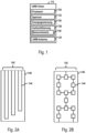
- FIGs 2A and 2B show exemplary antenna structures 142 of the UWB antenna of a UWB token.
- the antenna structures 142 each comprise a plurality of antenna elements 144, which in the case of the Figure 2A strip-shaped and, in the case of Figure 2B, flat.
- the antenna elements are, for example, individual antennas which are coordinated with one another and form a patch antenna.
- the antenna structures 142 each have a geometric coding with an individual resonance pattern identifying the UWB token.
- FIG 3 shows an exemplary UWB token 112, which comprises a lanyard 140 for carrying the UWB token 112, for example, around a user's neck 150.
- the UWB antenna of the UWB token 112 is, for example, integrated into the lanyard 140.
- the UWB antenna comprises a plurality of conductive antenna structures, which have a geometric coding with an individual resonance pattern identifying the UWB token 112.
- strip-shaped and/or flat antenna elements of the antenna structures are arranged distributed along the extension direction of the lanyard 140.
- the strip-shaped and/or flat antenna elements extend along the extension direction of the lanyard 140.
- the movement of the UWB token 112 includes pendulum movements 152 that are characteristic of the individual user 150 of the UWB token 112. These pendulum movements 152 can be used to authenticate the user 150 using an authentication module of the UWB token 112 and/or to generate energy, for example by converting kinetic energy into electrical energy using an energy generation module of the UWB token 112.
- FIG. 4 shows an exemplary UWB token 112 in the form of a band, which has one or more sensors 154.
- the sensors 154 can comprise, for example, a motion sensor and/or sensors for detecting vital functions of a wearer of the band, such as pulse and/or breathing.
- a wearer of the band such as pulse and/or breathing.
- it can be determined, for example, whether the UWB token 112 is being worn, and/or the wearer of the UWB token 112 can be authenticated, for example using a movement pattern of the UWB token 112 detected by the sensors 154 when worn. by the wearer, a pulse pattern of the wearer detected by the sensors 154 and/or a breathing pattern of the wearer detected by the sensors 154.
- the band comprises a display device 156, which comprises, for example, a display and/or one or more LEDs 158.
- the display device 156 can, for example, display a result of an authentication, e.g. its success, using the one or more sensors 154.
- the display device 156 can, for example, display a charging status of an energy storage module, e.g. an accumulator, and/or an energy generation status of an energy generation module of the UWB token 112.
- Figure 5 shows an exemplary UWB surveillance system 100 for monitoring a spatial area 102, such as a restricted access spatial area.
- the spatial area 102 is a restricted access spatial area
- this restricted access spatial area is, for example, delimited from the surroundings and can only be entered via one or more entrances or exits 104.
- the spatial area is an indoor area within a building.
- the spatial area can also include an outdoor area outside a building.
- this outdoor area can be a restricted access area that is fenced in.
- a fence can, for example, include a fence, a wall and/or a hedge.
- a spatial area 102 with restricted access can, for example, be divided into a plurality of spatial sections 106, each of which can only be entered via one or more entrances or exits 108.
- the UWB monitoring system 100 comprises a plurality of UWB sensors 110 distributed over the spatial area 102.
- the UWB sensors 110 are configured to capture sensor data, such as position data, motion data, image data, sound data, vibration data, temperature data, structural data, gas concentration data, particle concentration data, etc.
- the UWB sensors 110 are configured to transmit the captured sensor data by means of UWB, ie via a UWB network provided by the UWB monitoring system 100.
- the UWB sensors 110 can be configured as UWB transceivers for forwarding UWB transmission signals within the monitoring system 100.
- the UWB monitoring system 100 may comprise one or more UWB transceivers 111 configured to forward the UWB transmission signals.
- the UWB network implemented by the monitoring system 100 is, for example, a digital radio network with a mesh topology, which is used to transmit the acquired sensor data using of UWB.
- sensor data is transmitted within the UWB-based radio network with mesh topology using a position-based routing method.
- data transmission of the UWB sensors 110 takes place exclusively by means of UWB.
- one or more of the UWB sensors 110 are additionally configured for at least partial and/or complete wired transmission of the acquired sensor data.
- all UWB sensors 110 are additionally configured for at least partial and/or complete wired transmission of the acquired sensor data.
- a UWB radar functionality can also be integrated and/or implemented for the detection of persons who do not carry a UWB token.
- the UWB sensors 110 include, for example, anonymization filters that are configured to filter the recorded sensor data. During the filtering process, personal sensor data is anonymized. Personal sensor data includes, for example, image data that can be used to identify people. The filtered sensor data is transmitted, for example, via the UWB network to a control module 116.
- the control module 116 can be a central control module or a decentralized control module.
- the control module 116 is configured, for example, to evaluate the sensor data recorded by the UWB sensors 110 to detect exceptional events, such as a dangerous situation or unauthorized access to the spatial area 102. Upon detection of an exceptional event, the anonymization of the personal sensor data is suspended for a limited period of time.
- the control module 116 is, for example, further configured to receive requests for recorded sensor data, to check authorization credentials for access to the corresponding sensor data and, in the event of a successful check, to grant access to the requested sensor data. In the event of a detected exceptional event, for example, access is also granted to personal sensor data, the anonymization of which is temporarily suspended.
- the authorization credentials can, for example, be based on authorization certificates and/or authorization profiles of the requesters, which define the access authorizations of the requesters. For example, all access authorizations assigned to a user and/or UWB token are stored in an authorization profile assigned to a user and/or UWB token.
- the scope of the access authorization granted can, according to embodiments, depend, for example, on whether an exceptional situation is detected.
- the monitoring system 100 can further be configured to identify and locate UWB tokens 112 within the spatial area 102 using UWB sensors 110. Identification is carried out, for example, using UWB signals the UWB tokens 112, each of which has an individual resonance pattern, based on which the UWB sensors 110 can identify the UWB tokens 112. For localization, for example, UBW localization signals 107 are used, which are sent from the UWB antennas 110 to the corresponding UWB tokens 112 and vice versa. Based on the time differences of the transmitted signals, the relative positions of the UBW tokens 112 to the permanently installed UWB antennas 110 and thus the positions of the UBW tokens 112 in the spatial area 102 can be precisely determined, for example by means of triangulation.
- the UWB tokens 112 identify, for example, users or carriers with access authorization to the spatial area 102 if this is a spatial area with restricted access. Furthermore, the UWB tokens 112 can define carrier-specific access authorizations if different access authorizations are required for individual spatial sections of the spatial area 102. The UWB tokens 112 can thus be used to determine where persons with access authorization are located. If persons are detected to whom no UWB token 112 can be assigned, this is an indication of an attempt at unauthorized intrusion, which is detected, for example, as an exception event.
- the UWB tokens 112 can also be configured as authentication modules and include an authentication sensor in the form of a motion sensor for recording authentication data of the user of the UWB token 112 in the form of movement data of the UWB token 112.
- the user of the UWB token 112 can be authenticated using the recorded authentication data.
- the user of the UWB token 112 is the user assigned to the UWB token 112.
- the position data of the UWB token 112 can therefore be used as the position data of the corresponding user.
- the user of the UWB token 112 is not the assigned user. This means that there is an attempt at manipulation, which can be effectively detected in this way.
- FIG. 6 shows an exemplary UWB monitoring system 100 for monitoring a spatial area 102.
- the UWB monitoring system shown largely corresponds to the one in Figure 5 shown UWB monitoring system, however, communication within the UWB monitoring system 100 is wired using a LAN network.
- the use of UWB and LAN can also be combined. For example, both are used simultaneously or UWB communication is implemented as failover in the event of a LAN network failure.
- the UWB monitoring system 100 comprises a plurality of UWB sensors 110 distributed over the spatial area 102.
- the UWB sensors 110 are configured to collect sensor data, such as position data, motion data, image data, sound data, vibration data, temperature data, structural data, gas concentration data, particle concentration data, etc.
- the UWB sensors 110 are connected to a local wired network with a control module 116 for controlling the operation of the UWB monitoring system 100 via LAN connections 115 for transmitting collected sensor data.
- the control module 116 is configured to control the UWB monitoring system 100.
- Some UWB sensors of the plurality of UWB sensors 110 comprise a control module with an emergency function.
- the emergency function comprises control functions at least for the local operation of a part of the UWB monitoring system 100 using a UWB mesh network.
- only the UWB sensors 110 with control module can be connected to the local wired network via LAN connections 115.
- the other UWB sensors 110 can be connected to the control module 116, for example, via UWB connections via the UWB sensors 110 with control module.
- the monitoring system 100 can also be configured to use the UWB sensors 110 to locate UWB tokens 112 within the spatial area 102.
- UBW localization signals 107 are used, which are sent from UWB sensors 110 configured as localization sensors to the corresponding UWB tokens 112 and vice versa.
- the local wired network can have any network topology.
- the UWB tokens 112 can each comprise an authentication module.
- FIG. 7 shows an exemplary UBW sensor 110.
- This UBW sensor 110 comprises a processor 120, which executes program instructions, which are stored, for example, in a memory 124 of the UBW sensor 110, and controls the UBW sensor 110 according to the program instructions.
- the UBW sensor 110 further comprises a sensor element 122, which is configured, for example, to capture optical, acoustic, chemical, thermal, electromagnetic and/or vibration-based sensor data. The captured sensor data can, for example, be processed depending on the sensor element used. 122 personal sensor data. If the UWB sensor 110 is configured to capture personal sensor data, the UWB sensor 110 further comprises an anonymization filter for anonymizing the personal sensor data, otherwise not.
- Anonymizing can include, for example, deleting the captured personal sensor data from the memory 124. Furthermore, anonymizing can include, for example, encrypting the captured personal sensor data.
- the UWB sensor 110 comprises a UWB antenna 126 for sending and receiving data using UWB.
- the captured sensor data is, for example, a UWB signal of a UWB token.
- the sensor element can be identical to the UWB antenna.
- the received UWB signal can have an individual resonance pattern identifying the transmitting UWB token. Execution of the program instructions by the processor 120 may cause the UBW sensor 110 to determine the individual resonance pattern and identify it by comparison with reference patterns 125 stored in the memory 124.
- Figure 8 shows an exemplary method for controlling a UWB monitoring system comprising a plurality of UWB sensors.
- the UWB sensors are configured for communication via UWB and comprise one or more UWB identification sensors configured to identify a UWB token.
- the method for identifying the UWB token comprises, in block 410, acquiring sensor data by one of the identification sensors in the form of receiving a UWB signal transmitted by the UWB token.
- the received UWB signal has an individual resonance pattern identifying the UWB token as a result of geometric coding of antenna structures of a UWB antenna of the UWB token used for transmission.
- the individual resonance pattern of the received UWB signal is determined.
- the determined individual resonance pattern is compared with reference patterns of a plurality of reference patterns. These reference patterns are stored, for example, in a memory of the UWB monitoring system and are each associated with a UWB token. In case a match between the determined individual resonance pattern and one of the reference patterns exceeds a predefined threshold, the UWB token associated with the corresponding reference pattern is identified as the transmitting UWB token.
- Figure 9 shows an exemplary method for controlling a UWB monitoring system.
- position data of the UWB token within the spatial area are determined using the localization sensors.
- a runtime measurement of UWB signals between the localization sensors and the UWB token is carried out, from which a current position of the UWB token can be determined, for example by means of triangulation and knowledge of the positions of the localization sensors. can.
- This determination of the position data of the UWB token can be repeated, for example continuously, and movements of the UWB token through the spatial area 102 can be tracked.
- an authentication request is sent to the authentication module to check the presence of the UWB token on the associated user.
- the UWB token comprises the authentication module and the authentication request is sent to the UWB token.
- an authentication confirmation is received from the authentication module. This authentication confirmation confirms successful validation of the recorded authentication data of the user, which indicates the presence of the UWB token on the user. Successful validation requires that there is a sufficient match between the recorded authentication data and the reference value.
- FIG 10 shows an exemplary method for authenticating a user of a UWB token.
- the authentication is a behavior-based authentication using movement data of the UWB token, which is caused by movements of the user who carries the UWB token.
- the UWB token comprises a band with which it is attached around a neck or wrist of the user.
- movement data of the UWB token is recorded by a motion sensor of the UWB token.
- the recorded movement data is entered into a classification module of the UWB token, which is configured or trained to recognize one or more generic movement patterns using movement data.
- a classification result is generated by the classification module as to whether the user carrying the UWB token is a user registered in the UWB token.
- an authentication signal is generated if the classification result meets a test criterion.
- the test criterion includes, for example, exceeding a threshold value for the probability that the user of the UWB token is a registered user.
- the authentication signal signals successful authentication of the user who carries the UWB token.
- FIG 11 shows an exemplary method for authenticating a user of a UWB token.
- Steps 430 to 434 correspond to steps 420 to 424 of Figure 10 and are, for example, repeatedly executed one after the other.
- the classification result generated in step 434 is stored in a memory of the UWB token.
- an authentication request is received. This authentication request can, for example, be received from a UWB monitoring system.
- the memory of the UWB token is accessed to read out a stored classification result and the classification result is read out from the memory of the UWB token. For example, the last stored classification result is read out.
- the read-out classification result is evaluated using the test criterion and, if the classification result meets a test criterion, an authentication signal is generated in block 444.
- Figure 12 shows an exemplary method for controlling a UWB monitoring system.
- sensor data in a spatial area is recorded by UWB sensors of the UWB monitoring system.
- the recorded sensor data can include personal sensor data.
- the recorded sensor data is filtered using anonymization filters of the UWB sensors.
- Personal sensor data is anonymized in the process. Such anonymization includes, for example, deleting or encrypting the sensor data to be anonymized.
- the recorded and filtered sensor data is evaluated to detect an exceptional event. This is done, for example, by a central or decentralized control module of the UWB monitoring system.
- a temporary suspension of the anonymization of the personal sensor data is initiated, for example by the control module.
- Figure 13 shows an exemplary method for controlling a UWB monitoring system.
- the UWB monitoring system for example a control module of the UWB monitoring system, receives a request to release recorded sensor data.
- an authorization certificate included in the request is checked, for example by the control module, for access to the requested sensor data.
- the authorization certificate can be, for example, an authorization certificate or an identifier of a stored authorization profile of the requester.
- access to the requested sensor data is released following a successful check of the authorization certificate. For example, the requested sensor data is sent to the requester or displayed on a local display device of the monitoring system.
Landscapes
- Engineering & Computer Science (AREA)
- Physics & Mathematics (AREA)
- Theoretical Computer Science (AREA)
- General Physics & Mathematics (AREA)
- Electromagnetism (AREA)
- Health & Medical Sciences (AREA)
- Toxicology (AREA)
- Computer Hardware Design (AREA)
- Microelectronics & Electronic Packaging (AREA)
- General Health & Medical Sciences (AREA)
- Artificial Intelligence (AREA)
- Computer Vision & Pattern Recognition (AREA)
- Measurement Of The Respiration, Hearing Ability, Form, And Blood Characteristics Of Living Organisms (AREA)
Claims (15)
- Jeton UWB (112) qui comprend une antenne UWB (134) destinée à transmettre et recevoir des signaux UWB, dans lequel l'antenne UWB (134) comprend une pluralité de structures d'antenne conductrices (142), dans lequel les structures d'antenne (142) ont un codage géométrique avec un motif de résonance individuel identifiant le jeton UWB (112), caractérisé en ce que le jeton UWB (112) comprend une bande (140), qui est conçue pour soutenir le jeton UWB (112), dans lequel l'antenne UWB (134) est intégrée au moins partiellement dans la bande (140) et étend au moins une partie des structures d'antenne conductrices (142) le long de la bande (140).
- Jeton UWB (112) selon la revendication 1, dans lequel les structures d'antenne conductrices (142) comprennent des éléments d'antenne en forme de bandelette et/ou plats (144), et/ou
dans lequel les structures d'antenne (142) comprennent une pluralité d'antennes individuelles mutuellement coordonnées qui forment une antenne planaire. - Jeton UWB (112) selon l'une quelconque des revendications 1 à 2, dans lequel le jeton UWB (112) comprend un module de récupération d'énergie (136) qui est configuré pour récupérer de l'énergie électrique pour le fonctionnement du jeton UWB (112) par conversion de l'énergie cinétique en énergie électrique, dans lequel l'énergie cinétique convertie comprend par exemple l'énergie cinétique d'un mouvement d'oscillation (152) de la bande (140) lorsque le jeton UWB (112) est porté.
- Jeton UWB (112) selon la revendication 3, dans lequel le module de récupération d'énergie (136) est configuré pour convertir l'énergie cinétique dans l'énergie électrique par utilisation d'une méthode électromagnétique, piézoélectrique et/ou électrostatique.
- Jeton UWB (112) selon l'une quelconque des revendications 1 à 4, dans lequel le jeton UWB (112) comprend un capteur de mouvement (139) destiné à détecter les données de mouvement de la bande (140) lorsque le jeton UWB (112) est porté par l'utilisateur (150), dans lequel les données de mouvement de la bande (140) comprennent des données des mouvements d'oscillation (152) de la bande (140) alors qu'elle est portée, dans lequel le jeton UWB (112) comprend en outre un module d'authentification (138) pour l'authentification basée sur le comportement de l'utilisateur (150), qui porte le jeton UWB (112), avec utilisation des données de mouvement détectées.
- Jeton UWB (112) selon la revendication 5, dans lequel le module d'authentification (138) comprend un module de classification, qui est configuré pour identifier un ou plusieurs motifs de mouvement génériques en utilisant les données de mouvement, dans lequel l'authentification basée sur le comportement de l'utilisateur (150) par le jeton UWB (112) comprend les étapes suivantes consistant à :• détecter les données de mouvement par l'intermédiaire du capteur de mouvement (139) du jeton UWB (112),• introduire les données de mouvements détectées dans le module de classification,• générer un résultat de classification par l'intermédiaire du module de classification déterminant si l'utilisateur (150) qui porte le jeton UWB (112) est un utilisateur enregistré dans le jeton UWB (112),• produire un signal d'authentification si le résultat de classification satisfait à un critère de vérification, dans lequel le signal d'authentification signale une authentification réussie de l'utilisateur (150) qui porte le jeton UWB (112).
- Jeton UWB (112) selon la revendication 6, dans lequel le jeton UWB (112) est configuré pour mettre en œuvre de manière répétée, l'une après l'autre, les étapes consistant à détecter les données de mouvement, introduire les données de mouvement et générer le résultat de classification,dans lequel l'authentification basée sur le comportement de l'utilisateur (150) par le jeton UWB (112) comprend en outre un stockage du résultat de classification généré dans une mémoire du jeton UWB (112),dans lequel la génération du signal comprend les étapes consistant à :• en réponse à une requête d'authentification, accéder à la mémoire du jeton UWB (112) pour lire le résultat de classification stocké,• lire le résultat de classification dans la mémoire du jeton UWB (112),• évaluer le résultat de classification lu avec utilisation du critère de vérification.
- Jeton UWB (112) selon l'une quelconque des revendications 1 à 7, dans lequel la bande (140) comprend un élément de maintien qui est configuré pour maintenir un objet.
- Jeton UWB (112) selon la revendication 1 à 8, dans lequel la bande (140) est une lanière qui est conçue de telle sorte que le jeton UWB (112) peut être porté autour du cou de l'utilisateur (150).
- Système de surveillance UWB (100) destiné à surveiller une zone d'espace (102), dans lequel le système de surveillance UWB (100) comprend une pluralité de capteurs UWB (110), qui sont agencés de manière distribuée dans la zone d'espace (102) et sont configurés pour la détection de données de capteurs, dans lequel les capteurs UWB (110) sont configurés pour une communication au moyen d'UWB,
dans lequel la pluralité de capteurs UWB (110) comprend un ou plusieurs capteurs d'identification UWB qui sont configurés pour identifier au moins un jeton UWB (112) selon l'une quelconque des revendications 1 à 9, dans lequel une pluralité de motifs de référence (125) sont stockés dans une mémoire (124) du système de surveillance UWB (100) et chacun desdits motifs est associé à un jeton UWB, dans lequel l'identification comprend les étapes consistant à :• détecter des données de capteurs par l'intermédiaire de l'un des capteurs d'identification sous forme de la réception d'un signal UWB transmis par le jeton UWB (112), lequel signal UWB comprend un motif de résonance individuel identifiant le jeton UWB (112) en tant que résultat d'un codage géométrique de structures d'antenne (142) d'une antenne UWB (134) utilisée pour la transmission,• déterminer le motif de résonance individuel,• comparer le motif de résonance individuel déterminé avec les motifs de référence (125) de la pluralité de motifs de référence (125),• dans le cas où la concordance entre les motifs de résonance individuelle déterminés et un des motifs de référence dépasse une valeur seuil prédéfinie, identifier le jeton UWB associé au motif de référence correspondant en tant que jeton UWB (112) de transmission. - Système de surveillance UWB (100) selon la revendication 10, dans lequel le système de surveillance UWB comprend l'au moins un jeton UWB (112) et/ou
dans lequel la pluralité de capteurs UWB (110) comprend une pluralité de capteurs d'identification UWB, qui sont en outre configurés pour déterminer les données de position du jeton UWB (112) à l'intérieur de la zone spatiale (102), dans lequel la détermination des données de position comprend des mesures de durée d'exécution des signaux UWB (107) entre les capteurs de localisation UWB et le jeton UWB (112). - Système de surveillance UWB (100) selon l'une quelconque des revendications 10 à 11, dans lequel les données de capteurs détectées par la pluralité de capteurs UWB (110) comprennent des données de capteurs personnels et le système de surveillance UWB (100) est configuré pour• détecter des données de capteurs dans la zone d'espace (102), lesdites données comprenant des données de capteurs personnels,• filtrer les données de capteurs détectées en utilisant un filtre d'anonymisation (123), dans lequel le filtre d'anonymisation est configuré pour anonymiser les données de capteurs personnels,• évaluer les données de capteurs détectées pour détecter un événement exceptionnel,• en réponse à la détection de l'événement exceptionnel, suspendre l'anonymisation des données de capteurs personnels d'une manière limitée dans le temps.
- Système de surveillance UWB (100) selon la revendication 12, dans lequel l'événement exceptionnel comprend une tentative échouée pour identifier le jeton UWB (112).
- Système de surveillance UWB (100) selon l'une quelconque des revendications 12 à 13, dans lequel l'anonymisation par le filtre d'anonymisation (123) comprend un chiffrage d'au moins certaines des données de capteurs personnels, dans lequel la suspension limitée dans le temps de l'anonymisation comprend une fourniture limitée dans le temps des données de capteurs personnels correspondantes sous forme non chiffrée et/ou
dans lequel le système de surveillance UWB (100) est en outre configuré pour• recevoir une requête pour libérer les données de capteurs détectées,• vérifier une preuve d'autorisation, incluse dans la requête, pour accéder aux données de capteurs requises,• en réponse à une vérification réussie de la preuve d'autorisation, accorder l'accès aux données de capteurs requises. - Méthode de commande d'un système de surveillance UWB (100) destiné à surveiller une zone d'espace (102), dans laquelle le système de surveillance UWB (100) comprend une pluralité de capteurs UWB (110), qui sont agencés de manière distribuée dans la zone d'espace (102) et sont configurés pour détecter des données de capteurs, dans laquelle les capteurs UWB (110) sont configurés pour une communication au moyen d'UWB,
dans laquelle la pluralité de capteurs UWB (110) comprend un ou plusieurs capteurs d'identification UWB qui sont configurés pour identifier au moins un jeton UWB (112) selon l'une quelconque des revendications 1 à 9, dans lequel une pluralité de motifs de référence (125) sont stockés dans une mémoire du système de surveillance UWB (100) et chacun desdits motifs de référence est associé à un jeton UWB (112), dans laquelle la méthode d'identification du jeton UWB (112) comprend les étapes consistant à :• détecter des données de capteurs par l'intermédiaire de l'un des capteurs d'identification sous forme de la réception d'un signal UWB transmis par le jeton UWB (112), lequel signal UWB comprend un motif de résonance individuel identifiant le jeton UWB en tant que résultat d'un codage géométrique de structures d'antenne (142) d'une antenne UWB (134) utilisée pour la transmission,• déterminer le motif de résonance individuel,• comparer le motif de résonance individuel déterminé avec les motifs de référence (125) de la pluralité de motifs de référence (125),• dans le cas où la concordance entre les motifs de résonance individuelle déterminés et un des motifs de référence dépasse une valeur seuil prédéfinie, identifier le jeton UWB associé au motif de référence correspondant en tant que jeton UWB (112) de transmission.
Applications Claiming Priority (2)
| Application Number | Priority Date | Filing Date | Title |
|---|---|---|---|
| DE102020101731.6A DE102020101731A1 (de) | 2020-01-24 | 2020-01-24 | UWB-Token |
| PCT/EP2021/051019 WO2021148381A1 (fr) | 2020-01-24 | 2021-01-19 | Jeton à bande ultra-large |
Publications (2)
| Publication Number | Publication Date |
|---|---|
| EP4094191A1 EP4094191A1 (fr) | 2022-11-30 |
| EP4094191B1 true EP4094191B1 (fr) | 2025-01-08 |
Family
ID=74191775
Family Applications (1)
| Application Number | Title | Priority Date | Filing Date |
|---|---|---|---|
| EP21700934.9A Active EP4094191B1 (fr) | 2020-01-24 | 2021-01-19 | Jeton à bande ultra-large |
Country Status (3)
| Country | Link |
|---|---|
| EP (1) | EP4094191B1 (fr) |
| DE (1) | DE102020101731A1 (fr) |
| WO (1) | WO2021148381A1 (fr) |
Family Cites Families (3)
| Publication number | Priority date | Publication date | Assignee | Title |
|---|---|---|---|---|
| CN104395915A (zh) * | 2011-12-07 | 2015-03-04 | Rfid技术有限公司 | Rfid及其装置和方法 |
| US9690962B2 (en) * | 2014-01-10 | 2017-06-27 | Vdw Design, Llc | Radio-frequency identification tags |
| CN105956645A (zh) * | 2016-05-13 | 2016-09-21 | 集美大学 | 一种无芯片电子标签 |
-
2020
- 2020-01-24 DE DE102020101731.6A patent/DE102020101731A1/de not_active Withdrawn
-
2021
- 2021-01-19 EP EP21700934.9A patent/EP4094191B1/fr active Active
- 2021-01-19 WO PCT/EP2021/051019 patent/WO2021148381A1/fr not_active Ceased
Also Published As
| Publication number | Publication date |
|---|---|
| DE102020101731A1 (de) | 2021-07-29 |
| EP4094191A1 (fr) | 2022-11-30 |
| WO2021148381A1 (fr) | 2021-07-29 |
Similar Documents
| Publication | Publication Date | Title |
|---|---|---|
| CA2729193C (fr) | Systeme de controle de l'acces fonde sur le comportement | |
| CN107690772B (zh) | 经由可穿戴设备无形指示胁迫 | |
| US20160092665A1 (en) | Liveness Detection for User Authentication | |
| US20190066415A1 (en) | Mobile-based access control system | |
| DE112018000759T5 (de) | Systeme und verfahren zur verwaltung des zugangs zu einem fahrzeug oder einem anderen objekt unter verwendung von umgebungsdaten | |
| Popescu | Controlling mobility: Embodying borders | |
| JPWO2019017440A1 (ja) | 入場管理システムおよび入場管理方法 | |
| EP3855403B1 (fr) | Système de surveillance uwb permettant de surveiller la présence d'un utilisateur | |
| EP4094235B1 (fr) | Uwb systeme de surveillance | |
| EP4094461B1 (fr) | Système de surveillance à protection contre les pannes | |
| EP3404570B1 (fr) | Procédé et système d'authentification comportementale | |
| EP4094191B1 (fr) | Jeton à bande ultra-large | |
| EP4094463B1 (fr) | Détection d'une présence d'un jeton uwb inconnu | |
| US10636264B2 (en) | Office building security system using fiber sensing | |
| DE102020101733A1 (de) | Berechtigungsmanagement mittels UWB-Tokens | |
| EP3487200B1 (fr) | Authentification basée sur le comportement à l'aide de la position de retour | |
| DE112014002576T5 (de) | Verbessertes Sicherheitssystem | |
| DE102020101732A1 (de) | Manipulationssicherung anhand von gerätspezifischen Toleranzen | |
| EP3855779A1 (fr) | Communication uwb avec une pluralité de schémas d'encodage de données uwb | |
| Garg et al. | A comparative study on vehicles safety systems | |
| EP3336736A1 (fr) | Jeton auxiliaire id destiné à l'authentification mulifacteur | |
| Ocheni et al. | Electrocardiogram based authentication scheme for smart home security | |
| Rotter | Security and privacy in RFID applications | |
| JP2015187805A (ja) | 認証システム及び認証器 |
Legal Events
| Date | Code | Title | Description |
|---|---|---|---|
| STAA | Information on the status of an ep patent application or granted ep patent |
Free format text: STATUS: UNKNOWN |
|
| STAA | Information on the status of an ep patent application or granted ep patent |
Free format text: STATUS: THE INTERNATIONAL PUBLICATION HAS BEEN MADE |
|
| PUAI | Public reference made under article 153(3) epc to a published international application that has entered the european phase |
Free format text: ORIGINAL CODE: 0009012 |
|
| STAA | Information on the status of an ep patent application or granted ep patent |
Free format text: STATUS: REQUEST FOR EXAMINATION WAS MADE |
|
| 17P | Request for examination filed |
Effective date: 20220824 |
|
| AK | Designated contracting states |
Kind code of ref document: A1 Designated state(s): AL AT BE BG CH CY CZ DE DK EE ES FI FR GB GR HR HU IE IS IT LI LT LU LV MC MK MT NL NO PL PT RO RS SE SI SK SM TR |
|
| DAV | Request for validation of the european patent (deleted) | ||
| DAX | Request for extension of the european patent (deleted) | ||
| P01 | Opt-out of the competence of the unified patent court (upc) registered |
Effective date: 20230526 |
|
| STAA | Information on the status of an ep patent application or granted ep patent |
Free format text: STATUS: EXAMINATION IS IN PROGRESS |
|
| 17Q | First examination report despatched |
Effective date: 20240118 |
|
| GRAP | Despatch of communication of intention to grant a patent |
Free format text: ORIGINAL CODE: EPIDOSNIGR1 |
|
| STAA | Information on the status of an ep patent application or granted ep patent |
Free format text: STATUS: GRANT OF PATENT IS INTENDED |
|
| INTG | Intention to grant announced |
Effective date: 20240906 |
|
| GRAS | Grant fee paid |
Free format text: ORIGINAL CODE: EPIDOSNIGR3 |
|
| GRAA | (expected) grant |
Free format text: ORIGINAL CODE: 0009210 |
|
| STAA | Information on the status of an ep patent application or granted ep patent |
Free format text: STATUS: THE PATENT HAS BEEN GRANTED |
|
| AK | Designated contracting states |
Kind code of ref document: B1 Designated state(s): AL AT BE BG CH CY CZ DE DK EE ES FI FR GB GR HR HU IE IS IT LI LT LU LV MC MK MT NL NO PL PT RO RS SE SI SK SM TR |
|
| REG | Reference to a national code |
Ref country code: GB Ref legal event code: FG4D Free format text: NOT ENGLISH |
|
| REG | Reference to a national code |
Ref country code: CH Ref legal event code: EP |
|
| REG | Reference to a national code |
Ref country code: DE Ref legal event code: R096 Ref document number: 502021006354 Country of ref document: DE |
|
| REG | Reference to a national code |
Ref country code: IE Ref legal event code: FG4D Free format text: LANGUAGE OF EP DOCUMENT: GERMAN |
|
| PGFP | Annual fee paid to national office [announced via postgrant information from national office to epo] |
Ref country code: AT Payment date: 20250417 Year of fee payment: 5 |
|
| REG | Reference to a national code |
Ref country code: LT Ref legal event code: MG9D |
|
| REG | Reference to a national code |
Ref country code: NL Ref legal event code: MP Effective date: 20250108 |
|
| PG25 | Lapsed in a contracting state [announced via postgrant information from national office to epo] |
Ref country code: NL Free format text: LAPSE BECAUSE OF FAILURE TO SUBMIT A TRANSLATION OF THE DESCRIPTION OR TO PAY THE FEE WITHIN THE PRESCRIBED TIME-LIMIT Effective date: 20250108 |
|
| PG25 | Lapsed in a contracting state [announced via postgrant information from national office to epo] |
Ref country code: RS Free format text: LAPSE BECAUSE OF FAILURE TO SUBMIT A TRANSLATION OF THE DESCRIPTION OR TO PAY THE FEE WITHIN THE PRESCRIBED TIME-LIMIT Effective date: 20250408 |
|
| PG25 | Lapsed in a contracting state [announced via postgrant information from national office to epo] |
Ref country code: FI Free format text: LAPSE BECAUSE OF FAILURE TO SUBMIT A TRANSLATION OF THE DESCRIPTION OR TO PAY THE FEE WITHIN THE PRESCRIBED TIME-LIMIT Effective date: 20250108 |
|
| PG25 | Lapsed in a contracting state [announced via postgrant information from national office to epo] |
Ref country code: PL Free format text: LAPSE BECAUSE OF FAILURE TO SUBMIT A TRANSLATION OF THE DESCRIPTION OR TO PAY THE FEE WITHIN THE PRESCRIBED TIME-LIMIT Effective date: 20250108 |
|
| PG25 | Lapsed in a contracting state [announced via postgrant information from national office to epo] |
Ref country code: ES Free format text: LAPSE BECAUSE OF FAILURE TO SUBMIT A TRANSLATION OF THE DESCRIPTION OR TO PAY THE FEE WITHIN THE PRESCRIBED TIME-LIMIT Effective date: 20250108 |
|
| PG25 | Lapsed in a contracting state [announced via postgrant information from national office to epo] |
Ref country code: NO Free format text: LAPSE BECAUSE OF FAILURE TO SUBMIT A TRANSLATION OF THE DESCRIPTION OR TO PAY THE FEE WITHIN THE PRESCRIBED TIME-LIMIT Effective date: 20250408 Ref country code: IS Free format text: LAPSE BECAUSE OF FAILURE TO SUBMIT A TRANSLATION OF THE DESCRIPTION OR TO PAY THE FEE WITHIN THE PRESCRIBED TIME-LIMIT Effective date: 20250508 |
|
| PG25 | Lapsed in a contracting state [announced via postgrant information from national office to epo] |
Ref country code: HR Free format text: LAPSE BECAUSE OF FAILURE TO SUBMIT A TRANSLATION OF THE DESCRIPTION OR TO PAY THE FEE WITHIN THE PRESCRIBED TIME-LIMIT Effective date: 20250108 |
|
| PG25 | Lapsed in a contracting state [announced via postgrant information from national office to epo] |
Ref country code: LV Free format text: LAPSE BECAUSE OF FAILURE TO SUBMIT A TRANSLATION OF THE DESCRIPTION OR TO PAY THE FEE WITHIN THE PRESCRIBED TIME-LIMIT Effective date: 20250108 Ref country code: PT Free format text: LAPSE BECAUSE OF FAILURE TO SUBMIT A TRANSLATION OF THE DESCRIPTION OR TO PAY THE FEE WITHIN THE PRESCRIBED TIME-LIMIT Effective date: 20250508 |
|
| PG25 | Lapsed in a contracting state [announced via postgrant information from national office to epo] |
Ref country code: GR Free format text: LAPSE BECAUSE OF FAILURE TO SUBMIT A TRANSLATION OF THE DESCRIPTION OR TO PAY THE FEE WITHIN THE PRESCRIBED TIME-LIMIT Effective date: 20250409 Ref country code: BG Free format text: LAPSE BECAUSE OF FAILURE TO SUBMIT A TRANSLATION OF THE DESCRIPTION OR TO PAY THE FEE WITHIN THE PRESCRIBED TIME-LIMIT Effective date: 20250108 |
|
| REG | Reference to a national code |
Ref country code: CH Ref legal event code: PL |
|
| PG25 | Lapsed in a contracting state [announced via postgrant information from national office to epo] |
Ref country code: SE Free format text: LAPSE BECAUSE OF FAILURE TO SUBMIT A TRANSLATION OF THE DESCRIPTION OR TO PAY THE FEE WITHIN THE PRESCRIBED TIME-LIMIT Effective date: 20250108 |
|
| PG25 | Lapsed in a contracting state [announced via postgrant information from national office to epo] |
Ref country code: LU Free format text: LAPSE BECAUSE OF NON-PAYMENT OF DUE FEES Effective date: 20250119 |
|
| PG25 | Lapsed in a contracting state [announced via postgrant information from national office to epo] |
Ref country code: SM Free format text: LAPSE BECAUSE OF FAILURE TO SUBMIT A TRANSLATION OF THE DESCRIPTION OR TO PAY THE FEE WITHIN THE PRESCRIBED TIME-LIMIT Effective date: 20250108 |
|
| REG | Reference to a national code |
Ref country code: DE Ref legal event code: R097 Ref document number: 502021006354 Country of ref document: DE |
|
| PG25 | Lapsed in a contracting state [announced via postgrant information from national office to epo] |
Ref country code: DK Free format text: LAPSE BECAUSE OF FAILURE TO SUBMIT A TRANSLATION OF THE DESCRIPTION OR TO PAY THE FEE WITHIN THE PRESCRIBED TIME-LIMIT Effective date: 20250108 |
|
| PG25 | Lapsed in a contracting state [announced via postgrant information from national office to epo] |
Ref country code: MC Free format text: LAPSE BECAUSE OF FAILURE TO SUBMIT A TRANSLATION OF THE DESCRIPTION OR TO PAY THE FEE WITHIN THE PRESCRIBED TIME-LIMIT Effective date: 20250108 |
|
| REG | Reference to a national code |
Ref country code: CH Ref legal event code: W10 Free format text: ST27 STATUS EVENT CODE: U-0-0-W10-W00 (AS PROVIDED BY THE NATIONAL OFFICE) Effective date: 20251015 |
|
| PG25 | Lapsed in a contracting state [announced via postgrant information from national office to epo] |
Ref country code: BE Free format text: LAPSE BECAUSE OF NON-PAYMENT OF DUE FEES Effective date: 20250131 |
|
| PG25 | Lapsed in a contracting state [announced via postgrant information from national office to epo] |
Ref country code: CH Free format text: LAPSE BECAUSE OF NON-PAYMENT OF DUE FEES Effective date: 20250131 |
|
| PG25 | Lapsed in a contracting state [announced via postgrant information from national office to epo] |
Ref country code: EE Free format text: LAPSE BECAUSE OF FAILURE TO SUBMIT A TRANSLATION OF THE DESCRIPTION OR TO PAY THE FEE WITHIN THE PRESCRIBED TIME-LIMIT Effective date: 20250108 Ref country code: CZ Free format text: LAPSE BECAUSE OF FAILURE TO SUBMIT A TRANSLATION OF THE DESCRIPTION OR TO PAY THE FEE WITHIN THE PRESCRIBED TIME-LIMIT Effective date: 20250108 |
|
| REG | Reference to a national code |
Ref country code: BE Ref legal event code: MM Effective date: 20250131 |
|
| PG25 | Lapsed in a contracting state [announced via postgrant information from national office to epo] |
Ref country code: RO Free format text: LAPSE BECAUSE OF FAILURE TO SUBMIT A TRANSLATION OF THE DESCRIPTION OR TO PAY THE FEE WITHIN THE PRESCRIBED TIME-LIMIT Effective date: 20250108 |
|
| PG25 | Lapsed in a contracting state [announced via postgrant information from national office to epo] |
Ref country code: SK Free format text: LAPSE BECAUSE OF FAILURE TO SUBMIT A TRANSLATION OF THE DESCRIPTION OR TO PAY THE FEE WITHIN THE PRESCRIBED TIME-LIMIT Effective date: 20250108 |
|
| RAP4 | Party data changed (patent owner data changed or rights of a patent transferred) |
Owner name: BUNDESDRUCKEREI GMBH |
|
| PLBE | No opposition filed within time limit |
Free format text: ORIGINAL CODE: 0009261 |
|
| STAA | Information on the status of an ep patent application or granted ep patent |
Free format text: STATUS: NO OPPOSITION FILED WITHIN TIME LIMIT |
|
| 26N | No opposition filed |
Effective date: 20251009 |
|
| PG25 | Lapsed in a contracting state [announced via postgrant information from national office to epo] |
Ref country code: IE Free format text: LAPSE BECAUSE OF NON-PAYMENT OF DUE FEES Effective date: 20250119 |
|
| PG25 | Lapsed in a contracting state [announced via postgrant information from national office to epo] |
Ref country code: IT Free format text: LAPSE BECAUSE OF FAILURE TO SUBMIT A TRANSLATION OF THE DESCRIPTION OR TO PAY THE FEE WITHIN THE PRESCRIBED TIME-LIMIT Effective date: 20250108 |
|
| PGFP | Annual fee paid to national office [announced via postgrant information from national office to epo] |
Ref country code: GB Payment date: 20260122 Year of fee payment: 6 |
|
| PGFP | Annual fee paid to national office [announced via postgrant information from national office to epo] |
Ref country code: DE Payment date: 20260120 Year of fee payment: 6 |
|
| PGFP | Annual fee paid to national office [announced via postgrant information from national office to epo] |
Ref country code: FR Payment date: 20260121 Year of fee payment: 6 |