EP4094644A1 - PANIER AVEC PLAQUE DE RECOUVREMENT AMOVIBLE POUR FRITEUSE À AIR ET FRITEUSE À AIR DOTÉE d'un PANIER AVEC PLAQUE DE RECOUVREMENT AMOVIBLE - Google Patents
PANIER AVEC PLAQUE DE RECOUVREMENT AMOVIBLE POUR FRITEUSE À AIR ET FRITEUSE À AIR DOTÉE d'un PANIER AVEC PLAQUE DE RECOUVREMENT AMOVIBLE Download PDFInfo
- Publication number
- EP4094644A1 EP4094644A1 EP22170135.2A EP22170135A EP4094644A1 EP 4094644 A1 EP4094644 A1 EP 4094644A1 EP 22170135 A EP22170135 A EP 22170135A EP 4094644 A1 EP4094644 A1 EP 4094644A1
- Authority
- EP
- European Patent Office
- Prior art keywords
- basket
- cover plate
- air
- air outlet
- hot air
- Prior art date
- Legal status (The legal status is an assumption and is not a legal conclusion. Google has not performed a legal analysis and makes no representation as to the accuracy of the status listed.)
- Granted
Links
Images


Classifications
-
- A—HUMAN NECESSITIES
- A47—FURNITURE; DOMESTIC ARTICLES OR APPLIANCES; COFFEE MILLS; SPICE MILLS; SUCTION CLEANERS IN GENERAL
- A47J—KITCHEN EQUIPMENT; COFFEE MILLS; SPICE MILLS; APPARATUS FOR MAKING BEVERAGES
- A47J37/00—Baking; Roasting; Grilling; Frying
- A47J37/06—Roasters; Grills; Sandwich grills
- A47J37/0623—Small-size cooking ovens, i.e. defining an at least partially closed cooking cavity
- A47J37/0629—Small-size cooking ovens, i.e. defining an at least partially closed cooking cavity with electric heating elements
- A47J37/0641—Small-size cooking ovens, i.e. defining an at least partially closed cooking cavity with electric heating elements with forced air circulation, e.g. air fryers
-
- A—HUMAN NECESSITIES
- A47—FURNITURE; DOMESTIC ARTICLES OR APPLIANCES; COFFEE MILLS; SPICE MILLS; SUCTION CLEANERS IN GENERAL
- A47J—KITCHEN EQUIPMENT; COFFEE MILLS; SPICE MILLS; APPARATUS FOR MAKING BEVERAGES
- A47J37/00—Baking; Roasting; Grilling; Frying
- A47J37/06—Roasters; Grills; Sandwich grills
- A47J37/0623—Small-size cooking ovens, i.e. defining an at least partially closed cooking cavity
- A47J37/0664—Accessories
-
- A—HUMAN NECESSITIES
- A47—FURNITURE; DOMESTIC ARTICLES OR APPLIANCES; COFFEE MILLS; SPICE MILLS; SUCTION CLEANERS IN GENERAL
- A47J—KITCHEN EQUIPMENT; COFFEE MILLS; SPICE MILLS; APPARATUS FOR MAKING BEVERAGES
- A47J36/00—Parts, details or accessories of cooking-vessels
- A47J36/32—Time-controlled igniting mechanisms or alarm devices
-
- F—MECHANICAL ENGINEERING; LIGHTING; HEATING; WEAPONS; BLASTING
- F24—HEATING; RANGES; VENTILATING
- F24C—DOMESTIC STOVES OR RANGES ; DETAILS OF DOMESTIC STOVES OR RANGES, OF GENERAL APPLICATION
- F24C15/00—Details
- F24C15/16—Shelves, racks or trays inside ovens; Supports therefor
-
- F—MECHANICAL ENGINEERING; LIGHTING; HEATING; WEAPONS; BLASTING
- F24—HEATING; RANGES; VENTILATING
- F24C—DOMESTIC STOVES OR RANGES ; DETAILS OF DOMESTIC STOVES OR RANGES, OF GENERAL APPLICATION
- F24C15/00—Details
- F24C15/32—Arrangements of ducts for hot gases, e.g. in or around baking ovens
- F24C15/322—Arrangements of ducts for hot gases, e.g. in or around baking ovens with forced circulation
-
- F—MECHANICAL ENGINEERING; LIGHTING; HEATING; WEAPONS; BLASTING
- F24—HEATING; RANGES; VENTILATING
- F24C—DOMESTIC STOVES OR RANGES ; DETAILS OF DOMESTIC STOVES OR RANGES, OF GENERAL APPLICATION
- F24C7/00—Stoves or ranges heated by electric energy
- F24C7/06—Arrangement or mounting of electric heating elements
- F24C7/067—Arrangement or mounting of electric heating elements on ranges
-
- F—MECHANICAL ENGINEERING; LIGHTING; HEATING; WEAPONS; BLASTING
- F24—HEATING; RANGES; VENTILATING
- F24H—FLUID HEATERS, e.g. WATER OR AIR HEATERS, HAVING HEAT-GENERATING MEANS, e.g. HEAT PUMPS, IN GENERAL
- F24H3/00—Air heaters
- F24H3/02—Air heaters with forced circulation
Definitions
- the present disclosure relates to the field of air fryers, and in particular to a basket with a detachable cover plate for an air fryer and an air fryer having a basket with a detachable cover plate.
- the air fryer is a cooking appliance which is popular among people at present.
- a cooking cavity is provided in the air fryer, a hot air device consisting of a heating pipe and a heat circulation fan is provided in an upper portion of the cooking cavity, and it can form a heat circulating airflow in the cooking cavity to cook food in a basket.
- Such air fryer has a single cooking mode, namely only one mode of hot-air frying and baking, and cannot meet the increasing requirements of people on various functions of air fryer products.
- the baskets used by the current air fryers generally include a basket body and a handle provided at a side of the basket body, wherein the basket body is of a top opening structure, hot air above the cooking cavity directly enters the basket body through the opening to fry and bake the food, meanwhile, smoke and steam of the product in the basket body both directly contact the hot air device and other electrical devices through the opening, that is, this kind of basket for an air fryer cannot isolate the steam or the like of the product from the electrical devices in the cooking process, which will affect the reliability and the service life of the whole product. Therefore, in summary, the prior art needs to be improved.
- a basket with a detachable cover plate for an air fryer including a basket body and a handle provided at a side of the basket body, a top portion of the basket body being of an opening structure, wherein a cover plate matched with the opening is provided at the opening of the basket, and the cover plate is detachably installed at the opening of the basket.
- the cover plate is snapped with the basket body, and one of the cover plate and the basket body is provided with a clamping groove, and the other is provided with a clamping position corresponding to the clamping groove.
- a plurality of clamping grooves opening in a same rotation direction are provided at intervals on a peripheral side of the cover plate, a plurality of corresponding clamping positions designed in a protruding manner are provided on a side wall of the basket body, and the clamping grooves are rotatably snapped with the clamping positions.
- the basket is a drawer-type basket
- a gas outlet pipe is provided at an edge of the cover plate, the gas outlet pipe is in communication with an inner cavity of the basket body, and the gas outlet pipe is provided at a side opposite to the handle.
- a bottom of the basket body is provided with a thermally conductive plate closely attached to a bottom wall of the basket body.
- a plurality of inner concave portions are provided on the bottom wall of the basket body, installation bases are provided in the inner concave portions, the thermally conductive plate is provided with installation holes corresponding to the installation bases, and the fasteners penetrate through the installation holes to fix the thermally conductive plate on the installation bases, wherein a threaded hole is provided on each installation base, the fasteners are screws matched with the threaded holes, the installation holes are wedge-shaped holes, and nuts of the fasteners are embedded in the installation holes.
- An air fryer having a basket with a detachable cover plate, including a cooking cavity located inside the air fryer, and a basket and a hot air device provided inside the cooking cavity, the basket being of an upper opening structure, the hot air device being located above the basket, wherein the basket is the above basket with a detachable cover plate for an air fryer, an interior of the basket is hermetically isolated by the cover plate from the hot air device, and when the cover plate is detached from the upper opening of the basket, the interior of the basket is in communication with the hot air device.
- a bottom heating device capable of heating the basket is provided at a bottom and/or a side portion of the cooking cavity.
- a bottom heating device capable of heating the basket is provided at the bottom of the cooking cavity, the bottom heating device includes a heating pipe, a first thermally conductive aluminum plate, and a metal shell which are connected in sequence from bottom to top, the metal shell is provided at the bottom of the cooking cavity, and the basket is supported on the metal shell.
- the air fryer further includes a control system and a cover plate sensing system electrically connected with each other, and the cover plate sensing system is provided correspondingly to the cover plate.
- the cover plate sensing system When the cover plate is installed on the basket, the cover plate sensing system outputs a first signal to the control system; and when the cover plate is not installed on the basket, the cover plate sensing system outputs a second signal to the control system.
- control system has a hot air device starting mode and a bottom heating device starting mode
- the cover plate sensing system includes a micro-switch assembly and an ejector rod, the micro-switch assembly is electrically connected to the control system, and two ends of the ejector rod are respectively provided correspondingly to the micro-switch assembly and the cover plate, wherein
- the cover plate when the cover plate is installed on the basket, the interior of the basket is hermetically isolated by the cover plate from the hot air device, a gas outlet pipe in communication with an inner cavity of the basket is provided at an edge of the cover plate, and a first air outlet making the gas outlet pipe be in communication with the outside is provided on the air fryer.
- a sealing gasket is provided at a connection position between the first air outlet and the gas outlet pipe, when the cover plate is not installed on the basket, the sealing gasket blocks the first air outlet; and when the cover plate is installed on the basket, the sealing gasket is open, and the inner cavity of the basket is in communication with the outside through the gas outlet pipe and the first air outlet.
- the sealing gasket is formed by a plurality of flap-shaped sealing lips that can be turned outward, when the cover plate is installed on the basket, the gas outlet pipe is inserted into the sealing gasket, the plurality of flap-shaped sealing lips are pushed to be unfolded, the gas outlet pipe is in communication with the first air outlet; and when the cover plate is not installed on the basket, the plurality of flap-shaped sealing lips gather together and block the first air outlet.
- a hot air outlet corresponding to the hot air device is provided in an upper portion of the cooking cavity, and the air fryer is provided with a second air outlet making the hot air outlet be in communication with the outside;
- a cold air cavity is provided outside the cooking cavity, the cold air cavity is provided with a cold air outlet in communication with the second air outlet, and the cold air outlet is located correspondingly to a position of the hot air outlet.
- an opening of the second air outlet in communication with the outside is provided close to an opening of the first air outlet in communication with the outside.
- the first air outlet and the second air outlet are of a one-piece structure.
- the cover plate is snapped with the basket body, and one of the cover plate and the basket body is provided with a clamping groove, and the other is provided with a clamping position corresponding to the clamping groove, wherein a plurality of clamping grooves opening in a same rotation direction are provided at intervals on a peripheral side of the cover plate, a plurality of corresponding clamping positions designed in a protruding manner are provided on a side wall of the basket body, and the clamping grooves are rotatably snapped with the clamping positions.
- the basket is a drawer-type basket
- a gas outlet pipe is provided at an edge of the cover plate
- the gas outlet pipe is in communication with an inner cavity of the basket body
- the gas outlet pipe is provided at a side opposite to the handle
- a bottom of the basket body is provided with a thermally conductive plate closely attached to a bottom wall of the basket body, and wherein a plurality of inner concave portions are provided on the bottom wall of the basket body, installation bases are provided in the inner concave portions
- the thermally conductive plate is provided with installation holes corresponding to the installation bases, and the fasteners penetrate through the installation holes to fix the thermally conductive plate on the installation bases, wherein a threaded hole is provided on each installation base, the fasteners are screws matched with the threaded holes, the installation holes are wedge-shaped holes, and nuts of the fasteners are embedded in the installation holes.
- orientation or positional relationships indicated by terms such as “upper”, “lower”, “inner”, and “outer”, if present, are based on orientation or positional relationships as shown in the drawings, or orientation or positional relationships of a product when being conventionally placed in use, merely for facilitating describing the present disclosure and simplifying the description, rather than indicating or suggesting that related devices or elements have to be in the specific orientation or configured and operated in a specific orientation, therefore, they should not be construed as limiting the present disclosure.
- terms such as “first” and “second”, if appear are merely for distinctive description, but should not be construed as indicating or implying importance in the relativity.
- horizontal does not mean that the parts are required to be absolutely horizontal or overhanging, but may be slightly inclined.
- horizontal it merely means that a structure is more horizontal in comparison with “vertical”, rather than being completely horizontal, while the structure can be slightly inclined.
- connection may be a fixed connection, a detachable connection, or an integrated connection; it may be a mechanical connection or an electrical connection; it may be direct joining or indirect joining through an intermediate medium, and it also may be inner communication between two elements.
- a connection may be a fixed connection, a detachable connection, or an integrated connection; it may be a mechanical connection or an electrical connection; it may be direct joining or indirect joining through an intermediate medium, and it also may be inner communication between two elements.
- the present disclosure provides an air fryer having a basket with a detachable cover plate, which can realize sealed isolation of a food cavity in the basket from a hot air device above the cooking cavity, making the air fryer have richer functions.
- an air fryer having a basket with a detachable cover plate, including a cooking cavity located inside the air fryer, and a basket and a hot air device provided inside the cooking cavity.
- the basket is of an upper opening structure, the hot air device is located above the basket, and a detachable cover plate is provided at the upper opening of the basket.
- a bottom heating device capable of heating the basket is provided at a bottom and/or a side portion of the cooking cavity.
- the air fryer further includes a control system and a cover plate sensing system electrically connected with each other, and the cover plate sensing system is provided correspondingly to the cover plate.
- the cover plate sensing system When the cover plate is installed on the basket, the cover plate sensing system outputs a first signal to the control system; and when the cover plate is not installed on the basket, the cover plate sensing system outputs a second signal to the control system.
- control system has a hot air device starting mode and a bottom heating device starting mode.
- control system controls to enter the bottom heating device starting mode.
- control system controls to enter the hot air device starting mode, or controls to enter the hot air device starting mode and the bottom heating device starting mode at the same time.
- the cover plate sensing system comprises a micro-switch assembly and an ejector rod
- the micro-switch assembly is electrically connected to the control system
- two ends of the ejector rod are respectively provided correspondingly to the micro-switch assembly and the cover plate.
- one end of the ejector rod abuts against the cover plate, and the other end drives the micro-switch assembly to be in a first position state, and the micro-switch assembly outputs the first signal to the control system.
- the cover plate When the cover plate is not installed on the basket, the cover plate releases the abutment against the ejector rod, the micro-switch assembly changes to a second position state, and the micro-switch assembly outputs a second signal to the control system.
- the micro-switch assembly includes an elastic sensing sheet, the elastic sensing sheet abuts against one end portion of the ejector rod, and the other end portion of the ejector rod is provided correspondingly to the cover plate.
- the cover plate sensing system further includes an ejector rod spring, the ejector rod spring is sleeved on the ejector rod, and the ejector rod spring pushes the ejector rod to move towards a side where the cover plate is located.
- the air fryer is provided with a limiting groove corresponding to the ejector rod and the ejector rod spring, and the ejector rod and the ejector rod spring are installed in the limiting groove.
- the cover plate sensing system is provided above the basket, and a lower end of the ejector rod extends downwards to abut against a top surface of the cover plate.
- a limiting recess corresponding to the ejector rod is provided on the top of the basket, and when the cover plate is not installed on the basket, the lower end of the ejector rod extends into the limiting recess.
- the present disclosure has the following beneficial effects.
- the present disclosure further provides an air outlet system of an air fryer having a detachable cover plate, which can realize sealed isolation of a food cavity in the basket from a hot air device above a cooking cavity, and realize more cooking functions, meanwhile, efficient operation can be ensured through the air outlet system when new functions are being used.
- an air outlet system of an air fryer having a detachable cover plate, wherein a cooking cavity is provided inside the air fryer, the cooking cavity is provided therein with a basket and a hot air device, the basket is of an upper opening structure, the hot air device is located above the basket, and a detachable cover plate is provided at an upper opening of the basket.
- the cover plate When the cover plate is installed on the basket, the interior of the basket is hermetically isolated by the cover plate from the hot air device.
- a gas outlet pipe in communication with an inner cavity of the basket is provided at an edge of the cover plate, and a first air outlet making the gas outlet pipe be in communication with the outside is provided on the air fryer.
- a sealing gasket is provided at a connection position between the first air outlet and the gas outlet pipe, when the cover plate is not installed on the basket, the sealing gasket blocks the first air outlet; and when the cover plate is installed on the basket, the sealing gasket is open, and the inner cavity of the basket is in communication with the outside through the gas outlet pipe and the first air outlet.
- the sealing gasket is formed by a plurality of flap-shaped sealing lips that can be turned outward, when the cover plate is installed on the basket, the gas outlet pipe is inserted into the sealing gasket, the plurality of flap-shaped sealing lips are pushed to expand, the gas outlet pipe is in communication with the first air outlet; and when the cover plate is not installed on the basket, the plurality of flap-shaped sealing lips gather together and block the first air outlet.
- the sealing gasket is formed by four flap-shaped sealing lips, and the four flap-shaped sealing lips form a cross-shaped structure.
- the air fryer includes a bracket for installing the first air outlet, and the sealing gasket is clamped and fixed at a connection position between the bracket and the first air outlet.
- a hot air outlet corresponding to the hot air device is provided in an upper portion of the cooking cavity, and the air fryer is provided with a second air outlet making the hot air outlet be in communication with the outside.
- a cold air cavity is provided outside the cooking cavity, the cold air cavity is provided with a cold air outlet in communication with the second air outlet, and the cold air outlet is corresponding to a position of the hot air outlet.
- an opening of the second air outlet in communication with the outside is provided close to an opening of the first air outlet in communication with the outside.
- the first air outlet and the second air outlet are of a one-piece structure.
- a bottom heating device capable of heating the basket is provided at a bottom and/or a side portion of the cooking cavity.
- the present disclosure has the following beneficial effects.
- the present disclosure further provides an air fryer having a bottom heating system, which can realize the cooking of food in a basket by heating a bottom of the basket, and can enrich the functions of the air fryer.
- an air fryer having a bottom heating system includes a cooking cavity provided inside the air fryer, and a basket and a hot air device provided inside the cooking cavity.
- the basket is of an upper opening structure, the hot air device is located above the basket, and a bottom heating device capable of heating the basket is provided at the bottom of the cooking cavity.
- the bottom heating device includes a heating pipe, a first thermally conductive aluminum plate, and a metal shell which are connected in sequence from bottom to top, wherein the metal shell is provided at the bottom of the cooking cavity, and the basket is supported on the metal shell.
- the bottom of the basket is provided with a second thermally conductive aluminum plate closely attached to a bottom wall of the basket, and the second thermally conductive aluminum plate is closely attached to and connected to the metal shell.
- the second thermally conductive aluminum plate is adhered to the bottom wall of the basket.
- installation bases are provided at the bottom of the basket, and the second thermally conductive aluminum plate is fixed on the installation bases through fasteners.
- a plurality of inner concave portions are provided on the bottom wall of the basket, installation bases are provided in the inner concave portions, the second thermally conductive aluminum plate is provided with installation holes corresponding to the installation bases, and the fasteners penetrate through the installation holes to fix the second thermally conductive aluminum plate on the installation bases.
- a threaded hole is provided on each installation base, the fasteners are screws matched with the threaded holes, the installation holes are wedge-shaped holes, and nuts of the fasteners are embedded in the installation holes.
- a lower bracket is provided at the bottom of the air fryer, the metal shell is fixed on the lower bracket, and an upper surface of the metal shell constitutes the bottom wall of the cooking cavity.
- an edge of the metal shell is provided with an annular protruding rim, and the bottom of the basket is located in an area enclosed by the annular protruding rim.
- a frying plate is provided inside the basket, a supporting portion corresponding to the frying plate is provided on an inner side of the basket, and a gap exists between the frying plate and a bottom surface of the basket.
- a detachable cover plate is provided at an upper opening of the basket, when the cover plate is installed on the basket, the interior of the basket is hermetically isolated by the cover plate from the hot air device, and when the cover plate is detached from the upper opening of the basket, the interior of the basket is in communication with the hot air device.
- the present disclosure has the following beneficial effects.
- the present disclosure further provides a basket with a detachable cover plate for an air fryer, which can realize making the basket be in open state and closed state, so that more cooking functions of the air fryer can be better matched.
- a basket with a detachable cover plate for an air fryer includes a basket body and a handle provided at a side of the basket body, wherein a top portion of the basket body is of an opening structure, a cover plate matched with the opening is provided at the opening of the basket, and the cover plate is detachably installed at the opening of the basket.
- a sealing ring is provided between the cover plate and the basket body, and the sealing ring is sleeved on the cover plate.
- the cover plate is snapped with the basket body, and one of the cover plate and the basket body is provided with a clamping groove, and the other is provided with a clamping position corresponding to the clamping groove.
- a plurality of clamping grooves opening in a same rotation direction are provided at intervals on a peripheral side of the cover plate, a plurality of corresponding clamping positions designed in a protruding manner are provided on a side wall of the basket body, and the clamping grooves are rotatably snapped with the clamping positions.
- the basket is a drawer-type basket
- a gas outlet pipe is provided at an edge of the cover plate, the gas outlet pipe is in communication with an inner cavity of the basket body, and the gas outlet pipe is provided at a side opposite to the handle.
- a bottom of the basket body is provided with a thermally conductive plate closely attached to a bottom wall of the basket body.
- the thermally conductive plate is adhered to the bottom wall of the basket body.
- a plurality of inner concave portions are provided on the bottom wall of the basket body, installation bases are provided in the inner concave portions, the thermally conductive plate is provided with installation holes corresponding to the installation bases, and the fasteners penetrate through the installation holes to fix the thermally conductive plate on the installation bases.
- a threaded hole is provided on each installation base, the fasteners are screws matched with the threaded holes, the installation holes are wedge-shaped holes, and nuts of the fasteners are embedded in the installation holes.
- a frying plate is provided inside the basket body, a supporting portion corresponding to the frying plate is provided on an inner side of the basket body, and a gap exists between the frying plate and a bottom surface of the basket body.
- the present disclosure has the following beneficial effects.
- this embodiment provides an air fryer having a basket with a detachable cover plate, including a cooking cavity located inside the air fryer, and a basket 10 and a hot air device 20 provided in the cooking cavity.
- the basket 10 is of an upper opening structure, the hot air device 20 is located above the basket 10, and a detachable cover plate 30 is provided at the upper opening of the basket 10.
- a detachable cover plate 30 is provided at the upper opening of the basket 10.
- the detachable cover plate 30 on the basket 10 By providing the detachable cover plate 30 on the basket 10, it can be realized that when the cover plate 30 is detached, the interior of the basket 10 is in communication with the hot air device 20 and the conventional hot-air frying-and-baking function can be performed; after the cover plate 30 is installed, the interior of the basket 10 is hermetically isolated by the cover plate 30 from the hot air device 20, in this case, the broiling and baking or steaming function can be performed in the basket 10, smoke and steam generated in the basket 10 are isolated by the cover plate 30, avoiding contact with the hot air device 20 and other electrical devices, thus, the service life and reliability of the air fryer will not be affected, that is, the practicability of the air fryer is ensured while the functions of the air fryer is enriched.
- the hot air device 20 includes a heat circulation fan 21 and a top heating pipe 22, wherein the heat circulation fan 21 is located right above the top heating pipe 22, the top heating pipe 22 is located right above the basket 10, the top heating pipe 22 can heat a circulating airflow driven by the heat circulation fan 21, and the heated hot airflow is blown into the basket 10, and can fry and bake the food in the basket.
- a bottom heating device 80 capable of heating the basket 10 is provided at the bottom of the cooking cavity, and the bottom heating device 80 can provide heat for the broiling and baking or steaming function performed in the basket 10, so that the air fryer has richer cooking functions.
- a design position of the bottom heating device 80 in the present disclosure is not limited thereto, and in another embodiment, the bottom heating device capable of heating the basket 10 may be provided at a side portion of the cooking cavity, and it may also provide heat for the broiling and baking or steaming function performed in the basket 10.
- the air fryer further includes a control system and a cover plate sensing system electrically connected with each other, and the cover plate sensing system is provided correspondingly to the cover plate 30.
- the cover plate sensing system When the cover plate 30 is installed on the basket 10, the cover plate sensing system outputs the first signal to the control system; and when the cover plate 30 is not installed on the basket 10, the cover plate sensing system outputs a second signal to the control system.
- the control system has a hot air device starting mode and a bottom heating device starting mode, and when receiving a first signal, the control system controls to enter the bottom heating device starting mode; and when receiving a second signal, the control system controls to enter the hot air device starting mode, or controls to enter the hot air device starting mode and the bottom heating device starting mode at the same time, i.e., only when the cover plate 30 is installed on the basket 10, the control system can perform the bottom heating device starting mode, and carry out the steaming function or the like, because in this case, the cover plate 30 can block the steam generated in the steaming function, and can avoid the steam from contacting the hot air device 20 and other electrical devices, then the practicability and reliability of the product can be ensured by means of electronic control.
- the basket 10 When the cover plate 30 is not installed on the basket 10, the basket 10 is open, in this case, it can be controlled to enter the hot air device starting mode, to perform the conventional hot-air frying-and-baking function. Without doubt, it may also be controlled to enter the hot air device starting mode and the bottom heating device starting mode at the same time, in this case, both upper and lower heating systems simultaneously heat the circulating hot air in the basket 10, then the overall heating efficiency is higher.
- the cover plate sensing system includes a micro-switch assembly 40 and an ejector rod 50, wherein the micro-switch assembly 40 is electrically connected to the control system, and two ends of the ejector rod 50 are respectively provided correspondingly to the micro-switch assembly 40 and the cover plate 30.
- the micro-switch assembly 40 When the cover plate 30 is installed on the basket 10, one end of the ejector rod 50 abuts against the cover plate 30, and the other end drives the micro-switch assembly 40 to be in a first position state, the micro-switch assembly 40 outputs the first signal to the control system, in this case, the control system controls to enter the bottom heating device starting mode, and the steaming function can be started; and when the cover plate 30 is not installed on the basket 10, the cover plate 30 releases the abutment against the ejector rod 50, the micro-switch assembly 40 changes to a second position state, and the micro-switch assembly 40 outputs a second signal to the control system, in this case, the control system controls to enter the hot air device starting mode, or controls to enter the hot air device starting mode and the bottom heating device starting mode at the same time, and cannot start the steaming function.
- the cover plate sensing system further includes an ejector rod spring 60.
- the ejector rod spring 60 is sleeved on the ejector rod 50, and the ejector rod spring 60 pushes the ejector rod 50 to move towards a side where the cover plate 30 is located, i.e., the ejector rod spring 60 makes the ejector rod 50 maintain a tendency of moving towards the cover plate 30, realizing a significant change in the position of the ejector rod 50 when the cover plate 30 is in two states of being installed or not installed, thus the installation state of the cover plate 30 is accurately acquired, and the signal is accurately sent to the micro-switch assembly 40.
- the air fryer is provided with a limiting groove 70 corresponding to the ejector rod 50 and the ejector rod spring 60, and the ejector rod 50 and the ejector rod spring 60 are installed in the limiting groove 70, thereby it can be ensured that the ejector rod 50 and the micro-switch assembly 40 can be reliably fitted, ensuring to accurately detect the installation state of the cover plate 30, thereby ensuring the reliability of the product.
- the cover plate sensing system is provided above the basket 10, and a lower end of the ejector rod 50 extends downwards to abut against a top surface of the cover plate 30, thus, a space above the basket 10 in the air fryer can be fully utilized, and meanwhile the ejector rod 50, under its own gravity, also has a tendency of moving downwards, which can ensure that even in the case where the ejector rod spring ages, judgment of the installation state of the cover plate 30 by the ejector rod 50 is also relatively accurate, thus further ensuring the reliability of the product.
- the ejector rod 50 is provided on a side where the handle of the drawer-type basket is located, a limiting recess 11 corresponding to the ejector rod 50 is provided on the top of the basket 10, and when the cover plate 30 is not installed on the basket 10, the lower end of the ejector rod 50 extends into the limiting recess 11, so that the basket 10 can be limited, preventing the basket 10 from slipping out from the cooking cavity during the cooking process.
- the ejector rod 50 not only can detect the installation state of the cover plate 30, but also can limit the basket 10 when the cover plate 30 is not installed, further improving the practicability of the product.
- the micro-switch assembly 40 includes an elastic sensing sheet 41, the elastic sensing sheet 41 abuts against one end portion of the ejector rod 50, and the other end portion of the ejector rod 50 is provided correspondingly to the cover plate 30.
- the elastic sensing sheet 41 makes the ejector rod 50 maintain a tendency of moving towards the cover plate 30, realizing a significant change in the position of the ejector rod 50 when the cover plate 30 is in two states of being installed or not installed, thus the installation state of the cover plate 30 is accurately acquired, and the signal is accurately sent to the micro-switch assembly 40.
- the ejector rod 50 is provided above an edge of the basket 10 away from the side where the handle of the basket is located, and the lower end of the ejector rod 50 extends downwards to abut against the top surface of the cover plate 30, thus, the space above the basket 10 in the air fryer can be fully utilized, and meanwhile the ejector rod 50, under its own gravity, also has a tendency of moving downwards, which can ensure that even in the case where the ejector rod spring ages and fails, judgment of the installation state of the cover plate 30 by the ejector rod 50 is also relatively accurate, thus ensuring the reliability of the product.
- this embodiment provides an air outlet system of an air fryer having a detachable cover plate.
- a cooking cavity is provided inside the air fryer, and the cooking cavity is provided therein with a basket 10 and a hot air device 20.
- the basket 10 is of an upper opening structure, the hot air device 20 is located above the basket 10, and a detachable cover plate 30 is provided at an upper opening of the basket 10.
- the cover plate 30 is installed on the basket 10, the interior of the basket 10 is hermetically isolated by the cover plate 30 from the hot air device 20.
- a gas outlet pipe 31 in communication with an inner cavity of the basket 10 is provided at an edge of the cover plate 30, and a first air outlet 140 making the gas outlet pipe 31 be in communication with the outside is provided on the air fryer.
- the detachable cover plate 30 By providing the detachable cover plate 30 on the basket 10, when the cover plate 30 is detached, the interior of the basket 10 is in communication with the hot air device 20 and the conventional hot-air frying-and-baking function can be performed; after the cover plate 30 is installed, the interior of the basket 10 is hermetically isolated by the cover plate 30 from the hot air device 20, in this case, the broiling and baking or steaming function can be performed in the basket 10, the smoke and steam generated in the basket 10 are isolated by the cover plate 30 to avoid contact with the hot air device 20 and other electrical devices, thus, the service life and reliability of the air fryer will not be affected; meanwhile, the edge of the cover plate 30 is provided with the gas outlet pipe 31 in communication with the inner cavity of the basket 10, and the gas outlet pipe 31 is in communication with the outside through the first air outlet 140, then the smoke or steam generated during the broiling and baking or steaming function can be discharged, ensuring that corresponding functions are performed efficiently and reliably, therefore, the present solution ensures the practicability of
- a sealing ring is provided between the cover plate 30 and the basket 10. Specifically, a ring of installation groove is formed on a peripheral side of the cover plate 30, and the sealing ring is sleeved on the installation groove on the cover plate 30.
- a sealing lip of the sealing ring is closely attached to an inner side wall of the opening of the basket 10, so that the cover plate 30 seals the whole opening of the basket 10, preventing the smoke and steam from diffusing out from the opening to affect other electrical devices.
- a sealing gasket 150 is provided at a joint between the first air outlet 140 and the gas outlet pipe 31.
- the sealing gasket 150 blocks the first air outlet 140; and when the cover plate 30 is installed on the basket 10, the sealing gasket 150 is open, and the inner cavity of the basket 10 is in communication with the outside through the gas outlet pipe 31 and the first air outlet 140. That is, only when the cover plate 30 is installed on the basket 10, the sealing gasket 150 is open, and the inner cavity of the basket 10 is made to be in communication with the outside through the gas outlet pipe 31 and the first air outlet 140, then the smoke or steam generated during the broiling and baking or steaming function can be discharged (as shown in FIG.
- the sealing gasket 150 blocks the first air outlet 140, avoiding loss of the hot air from the first air outlet 140, and thus ensuring the practicability of the product.
- the sealing gasket 150 is formed by a plurality of flap-shaped sealing lips that can be turned outward.
- the gas outlet pipe 31 on the cover plate 30 is inserted into the sealing gasket 150, and the plurality of flap-shaped sealing lips are pushed to be unfolded, in this case, the gas outlet pipe 31 is in communication with the first air outlet 140; and when the cover plate 30 is not installed on the basket 10, the plurality of flap-shaped sealing lips of the sealing gasket 150 which are not subjected to an external force gather together and block the first air outlet 140.
- the sealing gasket 150 adopting a structure of a plurality of flap-shaped sealing lips that can be turned outward, can also simplify the structure of the sealing gasket and reduce the cost while being capable of controlling to open or block the first air outlet 140 according to the installation state of the cover plate 30.
- the sealing gasket 150 is formed by four flap-shaped sealing lips, and the four flap-shaped sealing lips form a cross-shaped structure, which is optimal from the view of structural complexity and sealing reliability.
- the sealing gasket 150 also can be formed by other numbers of flap-shaped sealing lips that can be turned outward, which can also achieve the technical effect of controlling to open or block the first air outlet 140.
- the air fryer further includes a bracket 160 for installing the first air outlet 140, and the sealing gasket 150 is clamped and fixed at a joint between the bracket 160 and the first air outlet 140.
- the sealing gasket 150 can achieve sealed fit between the first air outlet 140 and the bracket 160, avoiding the leakage of smoke or steam from the joint into the air fryer; and on the other hand, the sealing gasket 150 is simple to assemble and easy to manufacture.
- the first air outlet 140 is provided with an installation groove corresponding to the sealing gasket 150, and the sealing gasket 150 is placed in the installation groove.
- a protruding compression bone (compression member) 161 corresponding to the sealing gasket 150 is provided on the bracket 160, and the compression bone 161 compresses and fixes the sealing gasket 150 in the installation groove.
- the hot air device 20 includes a heat circulation fan 21 and a top heating pipe 22, wherein the heat circulation fan 21 is located right above the top heating pipe 22, the top heating pipe 22 is located right above the basket 10, the top heating pipe 22 can heat a circulating airflow driven by the heat circulation fan 21, and the heated hot airflow is blown into the basket 10, and can fry and bake the food in the basket.
- a hot air outlet 23 corresponding to the hot air device 20 is provided in an upper portion of the cooking cavity, the air fryer is provided with a second air outlet 170 making the hot air outlet 23 be in communication with the outside, and the hot air outlet 23 is provided on an air duct plate in the upper portion of the cooking cavity, which can discharge the smoke generated during the conventional hot-air frying and baking of food, so that the practicality thereof is stronger.
- a cold air cavity is provided outside the cooking cavity, the cold air cavity is located outside the air duct plate, the cold air cavity is provided with a cold air outlet 24 in communication with the second air outlet 170, and the cold air outlet 24 is corresponding to a position of the hot air outlet 23, specifically, the cold air outlet 24 is located above the hot air outlet 23, therefore, the smoke discharged from the hot air outlet 23, when entering the second air outlet 170, will be mixed with cold air flowing in from the cold air outlet 24, and is finally discharged from the second air outlet 170 to the outside (as shown in FIG. 8 ), so that a temperature of a gas eventually discharged from the second air outlet 170 to the outside is greatly reduced, thus the gas discharged from the second air outlet 170 may be effectively prevented from scalding the user and wall temperature rise can be reduced.
- an opening of the second air outlet 170 in communication with the outside is provided close to an opening of the first air outlet 140 in communication with the outside, thus it can avoid designing multiple openings on an outer wall of the air fryer and affecting the appearance of the product.
- the first air outlet 140 and the second air outlet 170 are of a one-piece structure, i.e., an integrated structure, which, on one hand, can simplify the structure of the entire air outlet system, and reduce the production cost and the assembly cost, and on the other hand, ensures a beautiful appearance of the product and strong practicability.
- a bottom heating device 80 capable of heating the basket 10 is provided at the bottom of the cooking cavity, and the bottom heating device 80 can provide heat for the broiling and baking or steaming function performed in the basket 10, so that the air fryer has richer cooking functions.
- a design position of the bottom heating device 80 in the present disclosure is not limited thereto, and in another embodiment, the bottom heating device capable of heating the basket 10 may be provided at a side portion of the cooking cavity, and it may also provide heat for the broiling and baking or steaming function performed in the basket 10.
- a frying plate 90 is provided inside the basket body 10, and the frying plate 90 is placed on a supporting portion on an inner side of the basket body 10.
- the supporting portion is specifically a supporting step designed in a protruding manner.
- a gap exists between the frying plate 90 and a bottom surface of the basket body 10, and food is placed on the frying plate 90.
- an appropriate amount of water can be added into the basket body 10. The water does not directly soak the food. After being heated, the water will form steam, and the steam will rise and come into contact with the food on the frying plate 90, so that the food can be steamed, or the food on the frying plate can be moisturized, thus, the usage scenarios of the basket can be enriched.
- the present disclosure further provides an air fryer having a bottom heating system, including a cooking cavity provided inside the air fryer, and a basket 10 and a hot air device 20 provided inside the cooking cavity.
- the basket 10 is of an upper opening structure, the hot air device 20 is located above the basket 10, and a bottom heating device 1030 capable of heating the basket 10 is provided at the bottom of the cooking cavity.
- the bottom heating device 1030 includes a heating pipe 1031, a first thermally conductive aluminum plate 1032, and a metal shell 1033 which are connected in sequence from bottom to top, wherein the metal shell 1033 is provided at the bottom of the cooking cavity, and the basket 10 is supported on the metal shell 1033.
- the bottom heating system 30 can directly heat the bottom of the basket 10 to broil and bake or steam food in the basket 10, thus the functions of the air fryer can be enriched; meanwhile, the heat of the bottom heating pipe 1031 is quickly and uniformly conducted by the first thermally conductive aluminum plate 1032, so that the temperature on the metal shell 1033 is higher and more uniform, thus having a better heating effect for the basket 10.
- the hot air device 20 includes a heat circulation fan 21 and a top heating pipe 22, wherein the heat circulation fan 21 is located right above the top heating pipe 22, the top heating pipe 22 is located right above the basket 10, the top heating pipe 22 can heat a circulating airflow driven by the heat circulation fan 21, and the heated hot airflow is blown into the basket 10, and can fry and bake the food in the basket.
- the bottom of the basket 10 is provided with a second thermally conductive aluminum plate 1040 closely attached to a bottom wall of the basket.
- the second thermally conductive aluminum plate 1040 is closely attached to and connected to the metal shell 1033, and can quickly and uniformly transfer the heat on the metal shell 1033 at the bottom of the basket 10 to the bottom wall of the basket 10, so that the food in the basket 10 can be better broiled and baked and steamed.
- installation bases 1050 are provided at the bottom of the basket 10, and the second thermally conductive plate 1040 is fixed on the installation bases 1050 through fasteners 1060.
- a plurality of inner concave portions 1011 are provided on the bottom wall of the basket 10, the installation bases 1050 are provided in the inner concave portions 1011, the second thermally conductive plate 1040 is provided with installation holes 1041 corresponding to the installation bases 1050, and the fasteners 1060 penetrate through the installation holes 1041 to fix the second thermally conductive plate 1040 on the installation bases 1050.
- the bottom wall of the basket 10 is not directly perforated, but the inner concave portions 1011 are designed to accommodate the installation bases 1050, so that the bottom of the basket 10 has better sealing performance, and there is no risk such as oil leakage and water leakage.
- the installation bases 1050 can be adhered or welded in the inner concave portions 1011.
- the installation bases 1050 are completely embedded in the inner concave portions 1011, therefore, the second thermally conductive plate 1040 can be completely closely attached to the bottom wall of the basket 10, ensuring good heat conduction performance.
- a threaded hole 1051 is provided on each installation base 1050, the fasteners 1060 are screws matched with the threaded holes 1051, the installation holes 1041 on the second thermally conductive plate 1040 are wedge-shaped holes, and nuts of the fasteners 1060 are embedded in the installation holes 1041.
- the manner of fixing with screws is quite convenient and reliable, and also has a low cost; secondly, after the second thermally conductive plate 1040 is fixed by the fasteners 1060, nut parts at the ends of the fasteners are also completely embedded into the wedge-shaped installation holes 1041, so that the bottom of the basket is flat and easy to place, and meanwhile has a beautiful appearance.
- a lower bracket 1070 is provided at the bottom of the air fryer, the metal shell 1033 is fixed on the lower bracket 1070, and an upper surface of the metal shell 1033 constitutes the bottom wall of the cooking cavity, thereby the structure of the whole cooking cavity can be simplified and meanwhile the heating effect at the bottom of the basket 10 is better; in addition, an edge of the metal shell 1033 is provided with an annular protruding rim 1034, and the bottom of the basket 10 is located in an area enclosed by the annular protruding rim 1034, which can further improve the heating efficiency.
- a frying plate 90 is provided inside the basket 10, and the frying plate 90 is placed on a supporting portion on an inner side of the basket 10.
- the supporting portion is specifically a supporting step designed in a protruding manner.
- a gap exists between the frying plate 90 and a bottom surface of the basket 10, and food is placed on the frying plate 90.
- an appropriate amount of water can be added into the basket 10. The water does not directly soak the food. After being heated, the water will form steam, and the steam will rise and come into contact with the food on the frying plate 90, so that the food can be steamed, or the food on the frying plate 90 can be moisturized, thus, the cooking functions of the basket can be enriched.
- a detachable cover plate 30 is provided at an upper opening of the basket 10.
- the cover plate 30 When the cover plate 30 is installed on the basket 10, the interior of the basket 10 is hermetically isolated by the cover plate 30 from the hot air device 20, and when the cover plate 30 is detached from the upper opening of the basket 10, the interior of the basket 10 is in communication with the hot air device 20.
- the interior of the basket 10 can be in communication with the hot air device 20 and the conventional hot-air frying-and-baking function can be performed; and after the cover plate 30 is installed, the interior of the basket 10 is hermetically isolated by the cover plate 30 from the hot air device 20 outside, in this case, cooking such as broiling and baking or steaming can be performed in the basket 10, the smoke and steam generated in the basket 10 are isolated by the cover plate 30, avoiding contact with the hot air device 20 and other electrical devices, thus, the service life and reliability of the air fryer will not be affected, that is, the practicability of the air fryer is ensured while the functions of the air fryer are enriched.
- the second thermally conductive plate 1040 is not fixed to the bottom of the basket through fasteners, but is adhered to the bottom wall of the basket 10, which not only can quickly and uniformly transfer the heat of the bottom heating device of the basket to the bottom wall of the basket 10, but also makes the structure of the basket as a whole simple and easy to produce.
- all of other structures are the same as those in the above first embodiment, and are not further repeated herein.
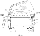
- this embodiment provides a basket with a detachable cover plate for an air fryer, including a basket body 10 and a handle 2020 provided at a side of the basket body 10.
- a top portion of the basket body 10 is of an opening structure, a cover plate 30 matched with the opening is provided at the opening of the basket 10, and the cover plate 30 is detachably installed at the opening of the basket 10, so that it can be realized that when the cover plate 30 is detached, the interior of the basket body 10 is in communication with the hot air device and the conventional hot-air frying-and-baking function can be performed; and after the cover plate 30 is installed, the interior of the basket body 10 is hermetically isolated by the cover plate 30 from the external hot air device, in this case, cooking such as broiling and baking or steaming can be performed in the basket body 10, the smoke and steam generated in the basket body 10 are isolated by the cover plate 30, avoiding contact with the hot air device and other electrical devices, thus, the service life and reliability of the air fryer will not be affected, that
- a sealing ring 2040 is provided between the cover plate 30 and the basket body 10. Specifically, a ring of installation groove is formed on a peripheral side of the cover plate 30, and the sealing ring 2040 is sleeved on the installation groove on the cover plate 30.
- a sealing lip of the sealing ring 2040 is closely attached to an inner side wall of the opening of the basket body 10, so that the cover plate 30 seals the whole opening of the basket body 10, preventing the smoke and steam from diffusing out from the opening to affect other electrical devices.
- the cover plate 30 is snapped with the basket body 10, one of the cover plate 30 and the basket body 10 is provided with a clamping groove 2031, and the other is provided with a clamping position 2011 corresponding to the clamping groove 2031.
- the snapping fit is convenient to disassemble and assemble.
- a specific structure of the present embodiment is that a plurality of clamping grooves 2031 opening in the same rotation direction are provided at intervals on a peripheral side of the cover plate 30, a plurality of corresponding clamping positions 2011 designed in a protruding manner are provided on a side wall of the basket body 10, and the clamping grooves 2031 are rotatably snapped with the clamping positions 2011, thereby on one hand, the structure can be simplified, facilitating the integrated molding of the clamping grooves 2031 and the cover plate 30, and also facilitating the integrated molding of the clamping positions 2011 and the basket body; meanwhile, the clamping positions 2011 and clamping grooves 2031 circumferentially provided at intervals can ensure the reliability of the fit between the cover plate 30 and the basket body 10; besides, by rotating the cover plate 30, it can be realized that the clamping grooves 2031 are snapped with the clamping positions 2011, i.e., the installation of the cover plate 30 is realized, and by rotating the cover plate 30, it also can be realized that the clamping grooves 2031 are separated from the clamp
- the basket is a drawer-type basket
- a gas outlet pipe 2032 is provided at an edge of the cover plate 30, the gas outlet pipe 2032 is in communication with an inner cavity of the basket body 10, the gas outlet pipe 2032 is provided at a side opposite to the handle 2020, and the gas outlet pipe 2032 is configured to guide out smoke and steam generated by broiling and baking and steaming food in the basket body 10, ensuring healthy, safe, and efficient cooking.
- the gas outlet pipe 2032 is provided at a side opposite to the handle 2020, therefore, when the drawer-type basket is pushed into the cooking cavity of the air fryer by the handle 2020, the gas outlet pipe 2032 is moved forward so that the gas outlet pipe can be better matched with a gas outlet channel on the air fryer; on the other hand, the gas outlet pipe 2032 also serves as a grip portion when the cover plate 30 is being disassembled and assembled.
- the gas outlet pipe 2032 By designing the gas outlet pipe at a side opposite to the handle 2020, a user can conveniently fix the basket body 10 with one hand by the handle 2020, and can disassemble and assemble the cover plate 30 by rotating the cover plate 30 by gripping the gas outlet pipe 2032 with one hand.
- the whole structure design is smart, and has quite high practicability.
- the bottom of the basket body 10 is provided with the thermally conductive plate 1040 closely attached to the bottom wall of the basket body.
- the thermally conductive plate 1040 is preferably a thermally conductive aluminum plate, which can quickly and uniformly transfer the heat of the bottom heating device of the basket to the bottom wall of the basket body 10, so that food in the basket body 10 can be better broiled and baked and steamed.
- installation bases 1050 are provided at the bottom of the basket body 10, and the thermally conductive plate 1040 is fixed on the installation bases 1050 through fasteners 1060.
- a plurality of inner concave portions 1011 are provided on the bottom wall of the basket body 10, the installation bases 1050 are provided in the inner concave portions 1011, the thermally conductive plate 1040 is provided with installation holes 1041 corresponding to the installation bases 1050, and the fasteners 1060 penetrate through the installation holes 1041 to fix the thermally conductive plate 1040 on the installation bases 1050.
- the bottom wall of the basket body 10 is not directly perforated, but the inner concave portions 1011 are designed to accommodate the installation bases 1050, so that the bottom of the basket body 10 has better sealing performance, and there is no risk such as oil leakage and water leakage.
- the installation bases 1050 can be adhered or welded in the inner concave portions 1011.
- the installation bases 1050 are completely embedded in the inner concave portions 1011, therefore, the thermally conductive plate 1040 can be completely closely attached to the bottom wall of the basket body 10, ensuring good heat conduction performance.
- a threaded hole 1051 is provided on each installation base 1050, the fasteners 1060 are screws matched with the threaded holes 1051, the installation holes 1041 on the thermally conductive plate 1040 are wedge-shaped holes, and nuts of the fasteners 1060 are embedded in the installation holes 1041.
- the manner of fixing with screws is quite convenient and reliable, and also has a low cost;
- nut parts at the ends of the fasteners are also completely embedded into the wedge-shaped installation holes 1041, so that the bottom of the basket is flat and easy to place, and meanwhile has a beautiful appearance.
- a frying plate 90 is provided inside the basket body 10, and the frying plate 90 is placed on a supporting portion on an inner side of the basket body 10.
- the supporting portion is specifically a supporting step designed in a protruding manner.
- a gap exists between the frying plate 90 and a bottom surface of the basket body 10, and food is placed on the frying plate 90.
- an appropriate amount of water can be added into the basket body 10. The water does not directly soak the food. After being heated, the water will form steam, and the steam will rise and come into contact with the food on the frying plate 90, so that the food can be steamed, or the food on the frying plate 90 can be moisturized, thus, the usage scenarios of the basket can be enriched.
- the thermally conductive plate 1040 is not fixed to the bottom of the basket body through fasteners 1060, but is adhered to the bottom wall of the basket body 10, which not only can quickly and uniformly transfer the heat of the bottom heating device of the basket to the bottom wall of the basket body 10, but also makes the structure of the basket as a whole simple and easy to produce.
- all of other structures are the same as those in the above first embodiment, and are not further repeated herein.
- the detachable cover plate on the basket by providing the detachable cover plate on the basket, it can be realized that when the cover plate is detached, the interior of the basket is in communication with the hot air device and the conventional hot-air frying-and-baking function can be performed; after the cover plate is installed, the interior of the basket is hermetically isolated by the cover plate from the hot air device, in this case, the broiling and baking or steaming function can be performed in the basket, without affecting the service life and reliability of the hot air device, that is, the functions of the air fryer can be enriched; meanwhile, the edge of the cover plate is provided with the gas outlet pipe in communication with the inner cavity of the basket, the gas outlet pipe is in communication with the outside through the first air outlet, then the smoke or steam generated during the broiling and baking or steaming function can be discharged, ensuring that corresponding functions are performed efficiently and reliably.
- the bottom heating device capable of heating the basket is provided at the bottom and/or the side portion of the cooking cavity, can provide heat for the broiling and baking or steaming function performed in the basket, and simplifies the product structure; by detecting whether the cover plate is in an installation state by the cover plate sensing system, and controlling the air fryer to start the hot air device starting mode and the bottom heating device starting mode according to the installation state of the cover plate, the air fryer product can be more intelligent, and meanwhile it avoids starting the steaming function when the cover plate is not installed, that is, avoiding the steam from damaging and affecting the hot air device and other electrical devices, thus rendering stronger practicability to the product;
- the cover plate sensing system includes the micro-switch assembly and the ejector rod, wherein the ejector rod is configured to mechanically contact the cover plate to produce displacement, and push the micro-switch assembly to produce a corresponding judgment signal, with a simple and reliable structure; besides, when the cover plate is not installed on the basket, the ejector rod further can
- the smoke and the exhaust can be discharged through the hot air outlet and the second air outlet, preferably being mixed with cold air before being discharged, with quite strong practicability.
- the opening of the second air outlet is provided close to the opening of the first air outlet, and the first air outlet and the second air outlet are of a one-piece structure, so that the structure is simple and convenient to install, and meanwhile the appearance of the product is more beautiful;
- the sealing gasket is formed by a plurality of flap-shaped sealing lips that can be turned outward, and when the cover plate is installed on the basket, the gas outlet pipe is inserted into the sealing gasket, the plurality of flap-shaped sealing lips are pushed to expand, and the gas outlet pipe is in communication with the first air outlet; and when the cover plate is not installed on the basket, the plurality of flap-shaped sealing lips gather together and block the first air outlet, then the sealing gasket has a simple structure and a low cost, and the sealing is reliable; the bottom heating system can directly heat the bottom of the
Landscapes
- Engineering & Computer Science (AREA)
- Chemical & Material Sciences (AREA)
- Combustion & Propulsion (AREA)
- Mechanical Engineering (AREA)
- General Engineering & Computer Science (AREA)
- Food Science & Technology (AREA)
- Physics & Mathematics (AREA)
- Thermal Sciences (AREA)
- Frying-Pans Or Fryers (AREA)
Applications Claiming Priority (4)
| Application Number | Priority Date | Filing Date | Title |
|---|---|---|---|
| CN202121122167.7U CN215937098U (zh) | 2021-05-24 | 2021-05-24 | 一种空气炸锅用带有可拆盖板的炸篮 |
| CN202121122217.1U CN215016354U (zh) | 2021-05-24 | 2021-05-24 | 一种具有可拆盖板式炸篮的空气炸锅 |
| CN202121125423.8U CN215127574U (zh) | 2021-05-24 | 2021-05-24 | 一种具有底部加热系统的空气炸锅 |
| CN202110566678.6A CN113180493A (zh) | 2021-05-24 | 2021-05-24 | 一种具有可拆盖板空气炸锅的出风系统 |
Publications (2)
| Publication Number | Publication Date |
|---|---|
| EP4094644A1 true EP4094644A1 (fr) | 2022-11-30 |
| EP4094644B1 EP4094644B1 (fr) | 2023-10-18 |
Family
ID=81387264
Family Applications (1)
| Application Number | Title | Priority Date | Filing Date |
|---|---|---|---|
| EP22170135.2A Active EP4094644B1 (fr) | 2021-05-24 | 2022-04-26 | Friteuse à air dotée d'un panier avec plaque de recouvrement amovible |
Country Status (1)
| Country | Link |
|---|---|
| EP (1) | EP4094644B1 (fr) |
Families Citing this family (3)
| Publication number | Priority date | Publication date | Assignee | Title |
|---|---|---|---|---|
| USD1101481S1 (en) | 2024-09-04 | 2025-11-11 | Sharkninja Operating Llc | Air fryer adapter |
| USD1101472S1 (en) | 2024-09-04 | 2025-11-11 | Sharkninja Operating Llc | Air fryer |
| USD1100567S1 (en) | 2024-09-04 | 2025-11-04 | Sharkninja Operating Llc | Air fryer |
Citations (3)
| Publication number | Priority date | Publication date | Assignee | Title |
|---|---|---|---|---|
| CN104586233A (zh) * | 2013-10-31 | 2015-05-06 | 深圳市联创三金电器有限公司 | 兼具烘烤功能的电煮锅 |
| EP3583878A1 (fr) * | 2018-06-18 | 2019-12-25 | Koninklijke Philips N.V. | Friteuse à air |
| WO2020163711A1 (fr) * | 2019-02-08 | 2020-08-13 | Sharkninja Operating Llc | Dispositif de cuisson et composants associés |
-
2022
- 2022-04-26 EP EP22170135.2A patent/EP4094644B1/fr active Active
Patent Citations (3)
| Publication number | Priority date | Publication date | Assignee | Title |
|---|---|---|---|---|
| CN104586233A (zh) * | 2013-10-31 | 2015-05-06 | 深圳市联创三金电器有限公司 | 兼具烘烤功能的电煮锅 |
| EP3583878A1 (fr) * | 2018-06-18 | 2019-12-25 | Koninklijke Philips N.V. | Friteuse à air |
| WO2020163711A1 (fr) * | 2019-02-08 | 2020-08-13 | Sharkninja Operating Llc | Dispositif de cuisson et composants associés |
Also Published As
| Publication number | Publication date |
|---|---|
| US20220369862A1 (en) | 2022-11-24 |
| EP4094644B1 (fr) | 2023-10-18 |
Similar Documents
| Publication | Publication Date | Title |
|---|---|---|
| EP4094644A1 (fr) | PANIER AVEC PLAQUE DE RECOUVREMENT AMOVIBLE POUR FRITEUSE À AIR ET FRITEUSE À AIR DOTÉE d'un PANIER AVEC PLAQUE DE RECOUVREMENT AMOVIBLE | |
| EP3406166B1 (fr) | Ensemble de cuisson multifonction | |
| US20220175171A1 (en) | Cooking utensil | |
| US6073542A (en) | Portable gas and electric griddle for outdoor-indoor applications | |
| CN212521494U (zh) | 一种多功能电热烹饪器具 | |
| CN114246451B (zh) | 烹饪器具 | |
| CN104720617A (zh) | 一种家用烧烤器 | |
| US12022977B2 (en) | Air fryer having broiling and baking functions | |
| JPS62234888A (ja) | 電気オ−ブンのための対流型送風機 | |
| US12616337B2 (en) | Basket with detachable cover plate for air fryer and air fryer having basket with detachable cover plate | |
| CN214964745U (zh) | 一种具有可拆盖板空气炸锅的出风系统 | |
| CN215937094U (zh) | 一种可视化空气炸锅的照明结构 | |
| CN214678592U (zh) | 多功能加热锅具 | |
| CN213993310U (zh) | 一种具有烤串功能的空气炸锅 | |
| CN116421066B (zh) | 烹饪器具 | |
| CN209610885U (zh) | 空气烤箱 | |
| CN215016354U (zh) | 一种具有可拆盖板式炸篮的空气炸锅 | |
| CN113180493A (zh) | 一种具有可拆盖板空气炸锅的出风系统 | |
| CN216984513U (zh) | 食物容器和烹饪器具 | |
| CN213345348U (zh) | 一种空气烤箱 | |
| WO2024212514A1 (fr) | Panier de friture à air et friteuse à air | |
| CN218606204U (zh) | 一种多容量组合的食物烹饪器具 | |
| CN215937098U (zh) | 一种空气炸锅用带有可拆盖板的炸篮 | |
| CN223169610U (zh) | 一种空气炸锅 | |
| CN116919190A (zh) | 一种烹饪器具及灶具 |
Legal Events
| Date | Code | Title | Description |
|---|---|---|---|
| PUAI | Public reference made under article 153(3) epc to a published international application that has entered the european phase |
Free format text: ORIGINAL CODE: 0009012 |
|
| STAA | Information on the status of an ep patent application or granted ep patent |
Free format text: STATUS: EXAMINATION IS IN PROGRESS |
|
| 17P | Request for examination filed |
Effective date: 20220426 |
|
| AK | Designated contracting states |
Kind code of ref document: A1 Designated state(s): AL AT BE BG CH CY CZ DE DK EE ES FI FR GB GR HR HU IE IS IT LI LT LU LV MC MK MT NL NO PL PT RO RS SE SI SK SM TR |
|
| GRAP | Despatch of communication of intention to grant a patent |
Free format text: ORIGINAL CODE: EPIDOSNIGR1 |
|
| STAA | Information on the status of an ep patent application or granted ep patent |
Free format text: STATUS: GRANT OF PATENT IS INTENDED |
|
| INTG | Intention to grant announced |
Effective date: 20230502 |
|
| GRAS | Grant fee paid |
Free format text: ORIGINAL CODE: EPIDOSNIGR3 |
|
| GRAA | (expected) grant |
Free format text: ORIGINAL CODE: 0009210 |
|
| STAA | Information on the status of an ep patent application or granted ep patent |
Free format text: STATUS: THE PATENT HAS BEEN GRANTED |
|
| AK | Designated contracting states |
Kind code of ref document: B1 Designated state(s): AL AT BE BG CH CY CZ DE DK EE ES FI FR GB GR HR HU IE IS IT LI LT LU LV MC MK MT NL NO PL PT RO RS SE SI SK SM TR |
|
| REG | Reference to a national code |
Ref country code: GB Ref legal event code: FG4D |
|
| REG | Reference to a national code |
Ref country code: CH Ref legal event code: EP |
|
| REG | Reference to a national code |
Ref country code: IE Ref legal event code: FG4D |
|
| REG | Reference to a national code |
Ref country code: DE Ref legal event code: R096 Ref document number: 602022000705 Country of ref document: DE |
|
| P01 | Opt-out of the competence of the unified patent court (upc) registered |
Effective date: 20231221 |
|
| REG | Reference to a national code |
Ref country code: LT Ref legal event code: MG9D |
|
| REG | Reference to a national code |
Ref country code: NL Ref legal event code: MP Effective date: 20231018 |
|
| REG | Reference to a national code |
Ref country code: AT Ref legal event code: MK05 Ref document number: 1621655 Country of ref document: AT Kind code of ref document: T Effective date: 20231018 |
|
| PG25 | Lapsed in a contracting state [announced via postgrant information from national office to epo] |
Ref country code: NL Free format text: LAPSE BECAUSE OF FAILURE TO SUBMIT A TRANSLATION OF THE DESCRIPTION OR TO PAY THE FEE WITHIN THE PRESCRIBED TIME-LIMIT Effective date: 20231018 |
|
| PG25 | Lapsed in a contracting state [announced via postgrant information from national office to epo] |
Ref country code: GR Free format text: LAPSE BECAUSE OF FAILURE TO SUBMIT A TRANSLATION OF THE DESCRIPTION OR TO PAY THE FEE WITHIN THE PRESCRIBED TIME-LIMIT Effective date: 20240119 |
|
| PG25 | Lapsed in a contracting state [announced via postgrant information from national office to epo] |
Ref country code: IS Free format text: LAPSE BECAUSE OF FAILURE TO SUBMIT A TRANSLATION OF THE DESCRIPTION OR TO PAY THE FEE WITHIN THE PRESCRIBED TIME-LIMIT Effective date: 20240218 |
|
| PG25 | Lapsed in a contracting state [announced via postgrant information from national office to epo] |
Ref country code: LT Free format text: LAPSE BECAUSE OF FAILURE TO SUBMIT A TRANSLATION OF THE DESCRIPTION OR TO PAY THE FEE WITHIN THE PRESCRIBED TIME-LIMIT Effective date: 20231018 |
|
| PG25 | Lapsed in a contracting state [announced via postgrant information from national office to epo] |
Ref country code: AT Free format text: LAPSE BECAUSE OF FAILURE TO SUBMIT A TRANSLATION OF THE DESCRIPTION OR TO PAY THE FEE WITHIN THE PRESCRIBED TIME-LIMIT Effective date: 20231018 |
|
| PG25 | Lapsed in a contracting state [announced via postgrant information from national office to epo] |
Ref country code: ES Free format text: LAPSE BECAUSE OF FAILURE TO SUBMIT A TRANSLATION OF THE DESCRIPTION OR TO PAY THE FEE WITHIN THE PRESCRIBED TIME-LIMIT Effective date: 20231018 |
|
| PG25 | Lapsed in a contracting state [announced via postgrant information from national office to epo] |
Ref country code: LT Free format text: LAPSE BECAUSE OF FAILURE TO SUBMIT A TRANSLATION OF THE DESCRIPTION OR TO PAY THE FEE WITHIN THE PRESCRIBED TIME-LIMIT Effective date: 20231018 Ref country code: IS Free format text: LAPSE BECAUSE OF FAILURE TO SUBMIT A TRANSLATION OF THE DESCRIPTION OR TO PAY THE FEE WITHIN THE PRESCRIBED TIME-LIMIT Effective date: 20240218 Ref country code: GR Free format text: LAPSE BECAUSE OF FAILURE TO SUBMIT A TRANSLATION OF THE DESCRIPTION OR TO PAY THE FEE WITHIN THE PRESCRIBED TIME-LIMIT Effective date: 20240119 Ref country code: ES Free format text: LAPSE BECAUSE OF FAILURE TO SUBMIT A TRANSLATION OF THE DESCRIPTION OR TO PAY THE FEE WITHIN THE PRESCRIBED TIME-LIMIT Effective date: 20231018 Ref country code: BG Free format text: LAPSE BECAUSE OF FAILURE TO SUBMIT A TRANSLATION OF THE DESCRIPTION OR TO PAY THE FEE WITHIN THE PRESCRIBED TIME-LIMIT Effective date: 20240118 Ref country code: AT Free format text: LAPSE BECAUSE OF FAILURE TO SUBMIT A TRANSLATION OF THE DESCRIPTION OR TO PAY THE FEE WITHIN THE PRESCRIBED TIME-LIMIT Effective date: 20231018 Ref country code: PT Free format text: LAPSE BECAUSE OF FAILURE TO SUBMIT A TRANSLATION OF THE DESCRIPTION OR TO PAY THE FEE WITHIN THE PRESCRIBED TIME-LIMIT Effective date: 20240219 |
|
| PG25 | Lapsed in a contracting state [announced via postgrant information from national office to epo] |
Ref country code: SE Free format text: LAPSE BECAUSE OF FAILURE TO SUBMIT A TRANSLATION OF THE DESCRIPTION OR TO PAY THE FEE WITHIN THE PRESCRIBED TIME-LIMIT Effective date: 20231018 Ref country code: RS Free format text: LAPSE BECAUSE OF FAILURE TO SUBMIT A TRANSLATION OF THE DESCRIPTION OR TO PAY THE FEE WITHIN THE PRESCRIBED TIME-LIMIT Effective date: 20231018 Ref country code: PL Free format text: LAPSE BECAUSE OF FAILURE TO SUBMIT A TRANSLATION OF THE DESCRIPTION OR TO PAY THE FEE WITHIN THE PRESCRIBED TIME-LIMIT Effective date: 20231018 Ref country code: NO Free format text: LAPSE BECAUSE OF FAILURE TO SUBMIT A TRANSLATION OF THE DESCRIPTION OR TO PAY THE FEE WITHIN THE PRESCRIBED TIME-LIMIT Effective date: 20240118 Ref country code: LV Free format text: LAPSE BECAUSE OF FAILURE TO SUBMIT A TRANSLATION OF THE DESCRIPTION OR TO PAY THE FEE WITHIN THE PRESCRIBED TIME-LIMIT Effective date: 20231018 Ref country code: HR Free format text: LAPSE BECAUSE OF FAILURE TO SUBMIT A TRANSLATION OF THE DESCRIPTION OR TO PAY THE FEE WITHIN THE PRESCRIBED TIME-LIMIT Effective date: 20231018 |
|
| PG25 | Lapsed in a contracting state [announced via postgrant information from national office to epo] |
Ref country code: DK Free format text: LAPSE BECAUSE OF FAILURE TO SUBMIT A TRANSLATION OF THE DESCRIPTION OR TO PAY THE FEE WITHIN THE PRESCRIBED TIME-LIMIT Effective date: 20231018 |
|
| REG | Reference to a national code |
Ref country code: DE Ref legal event code: R097 Ref document number: 602022000705 Country of ref document: DE |
|
| PG25 | Lapsed in a contracting state [announced via postgrant information from national office to epo] |
Ref country code: CZ Free format text: LAPSE BECAUSE OF FAILURE TO SUBMIT A TRANSLATION OF THE DESCRIPTION OR TO PAY THE FEE WITHIN THE PRESCRIBED TIME-LIMIT Effective date: 20231018 |
|
| PG25 | Lapsed in a contracting state [announced via postgrant information from national office to epo] |
Ref country code: SK Free format text: LAPSE BECAUSE OF FAILURE TO SUBMIT A TRANSLATION OF THE DESCRIPTION OR TO PAY THE FEE WITHIN THE PRESCRIBED TIME-LIMIT Effective date: 20231018 |
|
| PG25 | Lapsed in a contracting state [announced via postgrant information from national office to epo] |
Ref country code: SM Free format text: LAPSE BECAUSE OF FAILURE TO SUBMIT A TRANSLATION OF THE DESCRIPTION OR TO PAY THE FEE WITHIN THE PRESCRIBED TIME-LIMIT Effective date: 20231018 Ref country code: SK Free format text: LAPSE BECAUSE OF FAILURE TO SUBMIT A TRANSLATION OF THE DESCRIPTION OR TO PAY THE FEE WITHIN THE PRESCRIBED TIME-LIMIT Effective date: 20231018 Ref country code: RO Free format text: LAPSE BECAUSE OF FAILURE TO SUBMIT A TRANSLATION OF THE DESCRIPTION OR TO PAY THE FEE WITHIN THE PRESCRIBED TIME-LIMIT Effective date: 20231018 Ref country code: IT Free format text: LAPSE BECAUSE OF FAILURE TO SUBMIT A TRANSLATION OF THE DESCRIPTION OR TO PAY THE FEE WITHIN THE PRESCRIBED TIME-LIMIT Effective date: 20231018 Ref country code: EE Free format text: LAPSE BECAUSE OF FAILURE TO SUBMIT A TRANSLATION OF THE DESCRIPTION OR TO PAY THE FEE WITHIN THE PRESCRIBED TIME-LIMIT Effective date: 20231018 Ref country code: DK Free format text: LAPSE BECAUSE OF FAILURE TO SUBMIT A TRANSLATION OF THE DESCRIPTION OR TO PAY THE FEE WITHIN THE PRESCRIBED TIME-LIMIT Effective date: 20231018 Ref country code: CZ Free format text: LAPSE BECAUSE OF FAILURE TO SUBMIT A TRANSLATION OF THE DESCRIPTION OR TO PAY THE FEE WITHIN THE PRESCRIBED TIME-LIMIT Effective date: 20231018 |
|
| PLBE | No opposition filed within time limit |
Free format text: ORIGINAL CODE: 0009261 |
|
| STAA | Information on the status of an ep patent application or granted ep patent |
Free format text: STATUS: NO OPPOSITION FILED WITHIN TIME LIMIT |
|
| 26N | No opposition filed |
Effective date: 20240719 |
|
| PG25 | Lapsed in a contracting state [announced via postgrant information from national office to epo] |
Ref country code: SI Free format text: LAPSE BECAUSE OF FAILURE TO SUBMIT A TRANSLATION OF THE DESCRIPTION OR TO PAY THE FEE WITHIN THE PRESCRIBED TIME-LIMIT Effective date: 20231018 |
|
| PG25 | Lapsed in a contracting state [announced via postgrant information from national office to epo] |
Ref country code: SI Free format text: LAPSE BECAUSE OF FAILURE TO SUBMIT A TRANSLATION OF THE DESCRIPTION OR TO PAY THE FEE WITHIN THE PRESCRIBED TIME-LIMIT Effective date: 20231018 |
|
| PG25 | Lapsed in a contracting state [announced via postgrant information from national office to epo] |
Ref country code: MC Free format text: LAPSE BECAUSE OF FAILURE TO SUBMIT A TRANSLATION OF THE DESCRIPTION OR TO PAY THE FEE WITHIN THE PRESCRIBED TIME-LIMIT Effective date: 20231018 |
|
| PG25 | Lapsed in a contracting state [announced via postgrant information from national office to epo] |
Ref country code: MC Free format text: LAPSE BECAUSE OF FAILURE TO SUBMIT A TRANSLATION OF THE DESCRIPTION OR TO PAY THE FEE WITHIN THE PRESCRIBED TIME-LIMIT Effective date: 20231018 |
|
| PG25 | Lapsed in a contracting state [announced via postgrant information from national office to epo] |
Ref country code: LU Free format text: LAPSE BECAUSE OF NON-PAYMENT OF DUE FEES Effective date: 20240426 |
|
| REG | Reference to a national code |
Ref country code: BE Ref legal event code: MM Effective date: 20240430 |
|
| PG25 | Lapsed in a contracting state [announced via postgrant information from national office to epo] |
Ref country code: LU Free format text: LAPSE BECAUSE OF NON-PAYMENT OF DUE FEES Effective date: 20240426 |
|
| PG25 | Lapsed in a contracting state [announced via postgrant information from national office to epo] |
Ref country code: BE Free format text: LAPSE BECAUSE OF NON-PAYMENT OF DUE FEES Effective date: 20240430 |
|
| PG25 | Lapsed in a contracting state [announced via postgrant information from national office to epo] |
Ref country code: BE Free format text: LAPSE BECAUSE OF NON-PAYMENT OF DUE FEES Effective date: 20240430 |
|
| PG25 | Lapsed in a contracting state [announced via postgrant information from national office to epo] |
Ref country code: IE Free format text: LAPSE BECAUSE OF NON-PAYMENT OF DUE FEES Effective date: 20240426 |
|
| PGFP | Annual fee paid to national office [announced via postgrant information from national office to epo] |
Ref country code: DE Payment date: 20250417 Year of fee payment: 4 |
|
| PGFP | Annual fee paid to national office [announced via postgrant information from national office to epo] |
Ref country code: FR Payment date: 20250415 Year of fee payment: 4 |
|
| PG25 | Lapsed in a contracting state [announced via postgrant information from national office to epo] |
Ref country code: CY Free format text: LAPSE BECAUSE OF FAILURE TO SUBMIT A TRANSLATION OF THE DESCRIPTION OR TO PAY THE FEE WITHIN THE PRESCRIBED TIME-LIMIT; INVALID AB INITIO Effective date: 20220426 |
|
| PG25 | Lapsed in a contracting state [announced via postgrant information from national office to epo] |
Ref country code: HU Free format text: LAPSE BECAUSE OF FAILURE TO SUBMIT A TRANSLATION OF THE DESCRIPTION OR TO PAY THE FEE WITHIN THE PRESCRIBED TIME-LIMIT; INVALID AB INITIO Effective date: 20220426 |
|
| PG25 | Lapsed in a contracting state [announced via postgrant information from national office to epo] |
Ref country code: FI Free format text: LAPSE BECAUSE OF FAILURE TO SUBMIT A TRANSLATION OF THE DESCRIPTION OR TO PAY THE FEE WITHIN THE PRESCRIBED TIME-LIMIT Effective date: 20231019 |
|
| REG | Reference to a national code |
Ref country code: CH Ref legal event code: H13 Free format text: ST27 STATUS EVENT CODE: U-0-0-H10-H13 (AS PROVIDED BY THE NATIONAL OFFICE) Effective date: 20251125 |
|
| PG25 | Lapsed in a contracting state [announced via postgrant information from national office to epo] |
Ref country code: CH Free format text: LAPSE BECAUSE OF NON-PAYMENT OF DUE FEES Effective date: 20250430 |
|
| PGFP | Annual fee paid to national office [announced via postgrant information from national office to epo] |
Ref country code: GB Payment date: 20260306 Year of fee payment: 5 |