EP4094698A1 - Freisetzungsbeschränkende schleuse zur ermöglichung einer gestuften freisetzung nach produktabschnitt - Google Patents
Freisetzungsbeschränkende schleuse zur ermöglichung einer gestuften freisetzung nach produktabschnitt Download PDFInfo
- Publication number
- EP4094698A1 EP4094698A1 EP22185055.5A EP22185055A EP4094698A1 EP 4094698 A1 EP4094698 A1 EP 4094698A1 EP 22185055 A EP22185055 A EP 22185055A EP 4094698 A1 EP4094698 A1 EP 4094698A1
- Authority
- EP
- European Patent Office
- Prior art keywords
- medical device
- expandable medical
- constraining mechanism
- intermediate portion
- end portion
- Prior art date
- Legal status (The legal status is an assumption and is not a legal conclusion. Google has not performed a legal analysis and makes no representation as to the accuracy of the status listed.)
- Granted
Links
Images




Classifications
-
- A—HUMAN NECESSITIES
- A61—MEDICAL OR VETERINARY SCIENCE; HYGIENE
- A61B—DIAGNOSIS; SURGERY; IDENTIFICATION
- A61B17/00—Surgical instruments, devices or methods
- A61B17/11—Surgical instruments, devices or methods for performing anastomosis; Buttons for anastomosis
- A61B17/1114—Surgical instruments, devices or methods for performing anastomosis; Buttons for anastomosis of the digestive tract, e.g. bowels or oesophagus
-
- A—HUMAN NECESSITIES
- A61—MEDICAL OR VETERINARY SCIENCE; HYGIENE
- A61M—DEVICES FOR INTRODUCING MEDIA INTO, OR ONTO, THE BODY; DEVICES FOR TRANSDUCING BODY MEDIA OR FOR TAKING MEDIA FROM THE BODY; DEVICES FOR PRODUCING OR ENDING SLEEP OR STUPOR
- A61M27/00—Drainage appliance for wounds or the like, i.e. wound drains, implanted drains
- A61M27/002—Implant devices for drainage of body fluids from one part of the body to another
-
- A—HUMAN NECESSITIES
- A61—MEDICAL OR VETERINARY SCIENCE; HYGIENE
- A61B—DIAGNOSIS; SURGERY; IDENTIFICATION
- A61B17/00—Surgical instruments, devices or methods
- A61B17/00234—Surgical instruments, devices or methods for minimally invasive surgery
- A61B2017/00292—Surgical instruments, devices or methods for minimally invasive surgery mounted on or guided by flexible, e.g. catheter-like, means
-
- A—HUMAN NECESSITIES
- A61—MEDICAL OR VETERINARY SCIENCE; HYGIENE
- A61B—DIAGNOSIS; SURGERY; IDENTIFICATION
- A61B17/00—Surgical instruments, devices or methods
- A61B2017/00831—Material properties
- A61B2017/00867—Material properties shape memory effect
-
- A—HUMAN NECESSITIES
- A61—MEDICAL OR VETERINARY SCIENCE; HYGIENE
- A61B—DIAGNOSIS; SURGERY; IDENTIFICATION
- A61B17/00—Surgical instruments, devices or methods
- A61B17/11—Surgical instruments, devices or methods for performing anastomosis; Buttons for anastomosis
- A61B2017/1139—Side-to-side connections, e.g. shunt or X-connections
-
- A—HUMAN NECESSITIES
- A61—MEDICAL OR VETERINARY SCIENCE; HYGIENE
- A61M—DEVICES FOR INTRODUCING MEDIA INTO, OR ONTO, THE BODY; DEVICES FOR TRANSDUCING BODY MEDIA OR FOR TAKING MEDIA FROM THE BODY; DEVICES FOR PRODUCING OR ENDING SLEEP OR STUPOR
- A61M2210/00—Anatomical parts of the body
- A61M2210/10—Trunk
- A61M2210/1042—Alimentary tract
-
- A—HUMAN NECESSITIES
- A61—MEDICAL OR VETERINARY SCIENCE; HYGIENE
- A61M—DEVICES FOR INTRODUCING MEDIA INTO, OR ONTO, THE BODY; DEVICES FOR TRANSDUCING BODY MEDIA OR FOR TAKING MEDIA FROM THE BODY; DEVICES FOR PRODUCING OR ENDING SLEEP OR STUPOR
- A61M2210/00—Anatomical parts of the body
- A61M2210/10—Trunk
- A61M2210/1042—Alimentary tract
- A61M2210/1075—Gall bladder
Definitions
- This disclosure relates generally to medical devices, and more specifically, to medical devices for connecting tissue layers to create an anastomosis, implantable devices for occluding inhibiting or preventing material movement through tissue apertures, sealing, and allowing healing of defects in tissues, and deployment of the medical devices discussed herein.
- An anastomosis is a cross-connection between two tissue structures, such as blood vessels or intestines.
- tissue structures such as blood vessels or intestines.
- a graft vessel is anastomosed to a native coronary artery so that blood can flow through the graft vessel.
- Anastomoses can be created in various manners including, but not limited to: end-to-end, end-to-side, and side-to-side anastomoses. Often, suturing is used to create such anastomoses.
- the medical device systems may include an expandable medical device having a first end portion, a second end portion, and an intermediate portion between the first end portion and the second end portion.
- the intermediate portion of the expandable medical device may include a radially expansive force greater than a radially expansive force of at least one of the first end portion and the second end portion.
- the expandable medical device may include a first constraining mechanism configured to releasably constrain the expandable medical device, and a second constraining mechanism arranged between the expandable medical device and the first constraining mechanism and configured to lessen expansion of the intermediate portion of the expandable medical device in response to release of the first constraining mechanism.
- Various aspects of the present disclosure are also directed toward systems for deploying a medical device having a first flange, a second flange, and an intermediate portion therebetween and a delivery configuration and a deployed configuration.
- the systems include a first constraining mechanism configured to constrain the expandable medical device to the delivery configuration and deploy the first flange and the second flange to the deployed configuration in response to release thereof, and a second constraining mechanism arranged between the expandable medical device and the first constraining mechanism and configured to maintain the intermediate portion of the expandable medical device in an intermediate configuration in response to release of the first constraining mechanism.
- aspects of the disclosure are also directed toward methods of deploying an expandable medical device having a delivery configuration and a deployed configuration.
- the methods include positioning the expandable medical device at the target location (with expandable medical device including a first end portion, a second end portion, and an intermediate portion having a radially expansive force greater than a radially expansive force of the first end portion).
- the methods also include releasing a first constraining mechanism to deploy the first end portion and the second end portion to the deployed configuration and deploy the intermediate portion to an intermediate configuration. Further, the methods include releasing a second constraining mechanism to deploy the intermediate portion to the deployed configuration.
- a medical device system includes an expandable medical device including a first end portion, a second end portion, and an intermediate portion therebetween, the intermediate portion having a radially expansive force greater than a radially expansive force of at least one of the first end portion and the second end portion; a first constraining mechanism configured to releasably constrain the expandable medical device; and a second constraining mechanism arranged between the expandable medical device and the first constraining mechanism and configured to lessen expansion of the intermediate portion of the expandable medical device in response to release of the first constraining mechanism.
- the first constraining mechanism and the second constraining mechanism are configured to deploy the intermediate portion of the expandable medical device to an intermediate configuration and deploy the first end portion and the second end portion of the expandable medical device to a deployed configuration in response to release of the first constraining mechanism.
- the second constraining mechanism is configured to release and deploy the intermediate portion of the expandable medical device to the deployed configuration.
- the second constraining mechanism is configured to release in response to a force applied thereto.
- the force is a radial force applied within the intermediate portion of the expandable medical device, and the second constraining mechanism is configured to remain coupled to the expandable medical device subsequent to the force being applied thereto.
- the first end portion includes a first flange
- the second end portion includes a second flange
- the intermediate portion includes a substantially cylindrical shape
- the expandable medical device includes a first inflection area between the first flange and the intermediate portion, a second inflection area between the second flange and the intermediate portion, and the second constraining mechanism is arranged between the first inflection area and the second inflection area.
- Example 8 further to Example 1, the second constraining mechanism is coupled to the expandable medical device, and the first constraining mechanism is configured to deploy the expandable medical device and uncouple from the expandable medical device in response to tension applied to the first constraining mechanism.
- the first constraining mechanism is configured to releasably constrain the expandable medical device to a substantially cylindrical delivery configuration.
- the first constraining mechanism extends from a proximal end of the expandable medical device to a distal end of the expandable medical device and back toward a proximal end of the expandable medical device.
- Example 11 a system for deploying a medical device having a first flange, a second flange, and an intermediate portion therebetween, a delivery configuration, and a deployed configuration.
- the system includes: a first constraining mechanism configured to constrain the medical device to the delivery configuration and deploy the first flange and the second flange to the deployed configuration in response to release of the first constraining mechanism; and a second constraining mechanism arranged between the medical device and the first constraining mechanism and configured to maintain the intermediate portion of the medical device in an intermediate configuration in response to release of the first constraining mechanism.
- the intermediate portion includes a radially expansive force greater than a radially expansive force of at least one of the first flange and the second flange.
- the second constraining mechanism is coupled to the medical device and secured to the intermediate portion.
- the second constraining mechanism is arranged about a circumference of the intermediate portion of the medical device.
- a diameter of the intermediate portion in the intermediate configuration is approximately between 40% to 80% less than a diameter of the intermediate portion in the deployed configuration.
- the first constraining mechanism is configured to deploy the medical device and uncouple from the medical device in response to release of the first constraining mechanism.
- Example 17 a method of deploying an expandable medical device having a delivery configuration and a deployed configuration.
- the method includes positioning the expandable medical device at the target location, the expandable medical device including a first end portion, a second end portion, and an intermediate portion therebetween, the intermediate portion having a radially expansive force greater than a radially expansive force of the first end portion; releasing a first constraining mechanism to deploy the first end portion and the second end portion to the deployed configuration and deploy the intermediate portion to an intermediate configuration; and releasing a second constraining mechanism to deploy the intermediate portion to the deployed configuration.
- releasing the second constraining mechanism includes applying a force to the second constraining mechanism to deploy the intermediate portion to the deployed configuration from the intermediate configuration.
- a diameter of the intermediate portion in the intermediate configuration is approximately between 40% to 80% less than a diameter of the intermediate portion in the deployed configuration.
- releasing the first constraining mechanism includes uncoupling the first constraining mechanism from the expandable medical device, and releasing the second constraining mechanism includes maintaining at least a portion of the second constraining mechanism attached to the intermediate portion of the expandable medical device.
- a medical device system includes an expandable medical device including a first end portion, a second end portion, and an intermediate portion therebetween, the intermediate portion having a radially expansive force greater than a radially expansive force of at least one of the first end portion and the second end portion; a first constraining mechanism configured to releasably constrain the expandable medical device; and a second constraining mechanism arranged between the expandable medical device and the first constraining mechanism and configured to lessen expansion of the intermediate portion of the expandable medical device in response to release of the first constraining mechanism.
- the first constraining mechanism and the second constraining mechanism are configured to deploy the intermediate portion of the expandable medical device to an intermediate configuration and deploy the first end portion and the second end portion of the expandable medical device to a deployed configuration in response to release of the first constraining mechanism.
- the second constraining mechanism is configured to release and deploy the intermediate portion of the expandable medical device to the deployed configuration.
- the second constraining mechanism is configured to release in response to a force applied thereto.
- the force is a radial force applied within the intermediate portion of the expandable medical device, and the second constraining mechanism is configured to remain coupled to the expandable medical device subsequent to the force being applied thereto.
- the first end portion includes a first flange
- the second end portion includes a second flange
- the intermediate portion includes a substantially cylindrical shape
- the expandable medical device includes a first inflection area between the first flange and the intermediate portion, a second inflection area between the second flange and the intermediate portion, and the second constraining mechanism is arranged between the first inflection area and the second inflection area.
- the second constraining mechanism is coupled to the expandable medical device, and the first constraining mechanism is configured to deploy the expandable medical device and uncouple from the expandable medical device in response to tension applied to the first constraining mechanism.
- the first constraining mechanism is configured to releasably constrain the expandable medical device to a substantially cylindrical delivery configuration.
- the first constraining mechanism extends from a proximal end of the expandable medical device to a distal end of the expandable medical device and back toward a proximal end of the expandable medical device.
- a system for deploying a medical device having a first flange, a second flange, and an intermediate portion therebetween, a delivery configuration, and a deployed configuration with the system including: a first constraining mechanism configured to constrain the medical device to the delivery configuration and deploy the first flange and the second flange to the deployed configuration in response to release of the first constraining mechanism; and a second constraining mechanism arranged between the medical device and the first constraining mechanism and configured to maintain the intermediate portion of the medical device in an intermediate configuration in response to release of the first constraining mechanism.
- the intermediate portion includes a radially expansive force greater than a radially expansive force of at least one of the first flange and the second flange.
- the second constraining mechanism is coupled to the medical device and secured to the intermediate portion.
- the second constraining mechanism is arranged about a circumference of the intermediate portion of the medical device.
- a diameter of the intermediate portion in the intermediate configuration is approximately between 40% to 80% less than a diameter of the intermediate portion in the deployed configuration.
- the first constraining mechanism is configured to deploy the medical device and uncouple from the medical device in response to release of the first constraining mechanism.
- a method of deploying an expandable medical device having a delivery configuration and a deployed configuration including: positioning the expandable medical device at the target location, the expandable medical device including a first end portion, a second end portion, and an intermediate portion therebetween, the intermediate portion having a radially expansive force greater than a radially expansive force of the first end portion; releasing a first constraining mechanism to deploy the first end portion and the second end portion to the deployed configuration and deploy the intermediate portion to an intermediate configuration; and releasing a second constraining mechanism to deploy the intermediate portion to the deployed configuration.
- releasing the second constraining mechanism includes applying a force to the second constraining mechanism to deploy the intermediate portion to the deployed configuration from the intermediate configuration.
- a diameter of the intermediate portion in the intermediate configuration is approximately between 40% to 80% less than a diameter of the intermediate portion in the deployed configuration.
- releasing the first constraining mechanism includes uncoupling the first constraining mechanism from the expandable medical device, and releasing the second constraining mechanism includes maintaining at least a portion of the second constraining mechanism attached to the intermediate portion of the expandable medical device.
- Various aspects of the present disclosure are directed to medical devices for connecting tissue layers, for example, to circumvent a conduit or organ blockage, such as by creating a direct passage between tissue structures to create an anastomosis that facilitates material flow therebetween.
- the expandable medical devices may be endoscopically deployable or deliverable via a catheter and may be self-expanding to facilitate a secure connection between the tissue structures.
- the present disclosure discusses one or more constraining mechanisms that facilitate deployment of the expandable medical devices that facilitate delivery thereof and lessen misdeployment.
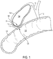
- FIG. 1 is a cutaway perspective view of an exemplary expandable medical device 100 implanted within a patient, according to various aspects of the present disclosure.
- the expandable medical device 100 is configured to be implanted in a patient to create a fluidic connection between spaces, tissue structures, conduits, organs, and the like, and combinations thereof.
- the expandable medical device 100 may be used to connect a gallbladder 102 (that defines an internal gallbladder space 104) with an intestine 106 (that defines an internal intestinal space 108).
- the expandable medical device 100 acts as a fluidic shunt device between the internal gallbladder space 104 and the internal intestinal space 108.
- Such an implementation may provide a beneficial treatment to the patient when, for example, a flow blockage exists in the native anatomical conduits connecting the internal gallbladder space 104 and the internal intestinal space 108.
- the patient may have one or more gallstones that cause a blockage of the patient's cystic duct 110 and/or common bile duct 112.
- the expandable medical device 100 may provide a fluidic passageway such that bile from the gallbladder 102 may flow into the intestine 106.
- the expandable medical device 100 may include a first end portion 114, a second end portion 116, and an intermediate portion 118 therebetween.
- the intermediate portion 118 defines a lumen 120 that extends longitudinally from the first end portion 114 to the second end portion 116.
- the lumen 120 may act as a connection (e.g., a shunt passageway) between the two spaces (e.g., tissue structures, conduits, organs) that the expandable medical device 100 connects.
- the lumen 120 acts as a connection between the internal gallbladder space 104 and the internal intestinal space 108, such that the internal gallbladder space 104 is in fluid communication with the internal intestinal space 108 via the expandable medical device 100.
- FIG. 1 shows the expandable medical device 100 connecting the gallbladder 102 and the intestine 106 of a patient
- the expandable medical device 100 may be used in conjunction with various body tissue structures and organs such as, but not limited to, stomachs, colons, small intestines, pancreases, blood vessels, bladders, kidneys, and conduits.
- FIG. 2 shows a delivery system 200 for an expandable medical device, according to various aspects of the present disclosure.
- the delivery system 200 may include a catheter body 202 upon which the expandable medical device (not shown) may be arranged.
- the delivery system 200 also includes a first constraining mechanism 204 configured to constrain the expandable medical device to a delivery or constrain configuration.
- the first constraining mechanism 204 may be used in connection with a second constraining mechanism (as shown and discussed in further detail below with reference to FIGS. 3-6 ).
- tension may be applied to a deployment line 206 coupled to the first constraining mechanism 204.
- the deployment line 206 is accessible to a user such as a physician and may be arranged through a port 208 in the catheter body 202.
- the primary constraining mechanism 204 may open, withdraw or evert from an end of the delivery system 200, such as a distal tip 210, toward the port 208.
- the first constraining mechanism 204 may have multiple layers constraining the expandable medical device and as such may move from one end of the delivery zone to the other end multiple times during deployment.
- the delivery system 200 may also include a skirt 212 that is arranged about the first constraining mechanism 204 prior to the delivery system 200 being traversed to a target location within a patient.
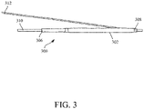
- FIG. 3 shows an expandable medical device 300 in a delivery configuration, according to various aspects of the present disclosure.
- a first constraining mechanism 302 is configured to constrain the expandable medical device 300 to the delivery configuration.
- the first constraining mechanism 302 extends between a proximal end 306 of the expandable medical device 300 to a distal end 308 of the expandable medical device 300.
- the expandable medical device 300 may be arranged on a delivery catheter or delivery system 310.
- the delivery catheter or delivery system 310 in certain instances, is routed within a patient to a target location for delivery of the expandable medical device 300.
- tension may be applied to a deployment line 312 coupled to the first constraining mechanism 302, which is accessible to a user such as a physician.
- the first constraining mechanism 302 may open, withdraw or evert from the proximal end 306 towards the distal end 308 and then continue back toward the proximal end 306 of the expandable medical device 300. Releasing the first constraining mechanism 302 in this manner may deploy the distal end 308 of the expandable medical device 300 prior to deploying the remaining portions of the expandable medical device 300.
- FIG. 4 shows the expandable medical device 300 after deployment of the distal end 308 of the expandable medical device 300.
- the expandable medical device 300 may include a first flange 314 arranged at the distal end 308.
- the first flange 314 may be deployed after the first constraining mechanism 302 is withdrawn past the first flange.
- the user may continue to apply tension to the deployment line 312 of the first constraining mechanism 302 to continue deployment of the expandable medical device 300.
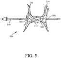
- FIG. 5 shows the expandable medical device 300 after deployment of the proximal end 306 of the expandable medical device 300.
- the expandable medical device 300 may include a second flange 316 arranged at the proximal end 306.
- the first constraining mechanism 302 has been released past the proximal end 306 of the expandable medical device 300, and released and uncoupled from the expandable medical device 300.
- the first constraining mechanism 302 is configured to release and deploy the first flange 314 and the second flange 316 to a fully-deployed configuration in response to release thereof.
- An intermediate portion 318 of the expandable medical device 300 remains in an intermediate configuration as shown in FIG. 5 .
- a second constraining mechanism 304 arranged between the expandable medical device 300 and the first constraining mechanism 302 in the delivery configuration shown in FIGs. 2 and 3 , is configured to maintain the intermediate portion 318 of the expandable medical device 300 in the intermediate configuration after the release of the first constraining mechanism 302.
- the intermediate portion 318 of the expandable medical device 300 may have a radially expansive force greater than a radially expansive force of one or both of the first flange 314 and the second flange 316 when they are constrained by the first constraining mechanism 302.
- the expandable medical device 300 may include a plurality of elongate elements.
- the plurality of elongate elements may have a greater density and/or winding pattern in the intermediate portion 318 of the expandable medical device 300 than in one or both of the first flange 314 and the second flange 316.
- the intermediate portion 318 of the expandable medical device 300 has a greater resistance to compressive force (a greater radial strength) than one or both of the first flange 314 and the second flange 316.
- the intermediate portion 318 is approximately cylindrical whereas the first flange 314 and the second flange 316 deploy approximately perpendicular to the intermediate portion 318 such that the expandable medical device 300 includes an hourglass shape having a lumen therethrough in an intermediate configuration (shown in FIG. 5 ).
- the second constraining mechanism 304 is coupled to the expandable medical device 300 and is secured to the intermediate portion 318.
- the second constraining mechanism 304 is arranged about a circumference of the intermediate portion 318 of the expandable medical device 300.
- the second constraining mechanism 304 may be configured to mitigate against premature expansion of the intermediate portion 318.
- the expandable medical device 300 in certain instances, is self-expanding and therefore is biased to deploy to the full-deployed configuration from the delivery configuration.
- the intermediate portion 318 and the first flange 314 and/or the second flange 316 having different radial forces may result in forces from the intermediate portion 318, desiring to be in the deployed configuration, to force the first constraining mechanism 302 from the expandable medical device 300.
- the second constraining mechanism 304 is configured to lessen expansion of the intermediate portion 318 by deploying the intermediate portion 318 to the intermediate configuration as opposed to directly to the deployed configuration.
- the second constraining mechanism 304 is configured to release in response to a force applied thereto.
- the force is applied from within the intermediate portion 318 of the expandable medical device 300 to break, fracture, or distend the second constraining mechanism 304.
- the second constraining mechanism 304 remains coupled to the intermediate portion 318 of the expandable medical device 300 after release thereof.
- the intermediate portion 318 of the expandable medical device 300 may deploy to the fully-deployed configuration, for example, as shown in FIG. 6B , after release of the second constraining mechanism 304.
- FIG. 6A shows an expandable medical device 600 and constraining mechanism 602, according to various aspects of the present disclosure, in an intermediate configuration.
- the expandable medical device 600 may include a first end portion 604 having a flange shape, a second end portion 606 having a flange shape, and an intermediate portion 608 extending therebetween.
- first end portion 604, the second end portion 606, and the intermediate portion 608 are formed by a framework of elongate elements 610.
- the elongate elements 610 in the intermediate portion 608 include a greater density than the first end portion 604 and the second end portion 606.
- the expandable medical device 600 may include a covering material 612 (which may also be referred to herein as a "covering").
- the covering material 612 is disposed on some or all of the first end portion 604, the second end portion 606, and the intermediate portion 608.
- the elongate elements 610 in the intermediate portion 608 include a greater concentration or greater windings than the first end portion 604 and the second end portion 606.
- the intermediate portion 608 has a greater resistance to radial forces than the first end portion 604 and the second end portion 606.
- the difference in density of the elongate elements 610 in the intermediate portion 608 and the first end portion 604 and the second end portion 606 causes the first end portion 604 and the second end portion 606 results in the intermediate portion 608 having a greater radial expansive force than the first end portion 604 and the second end portion 606.
- the intermediate portion 608 includes a radially expansive force greater than a radially expansive force than one or both of the first end portion 604 and the second end portion 606 in the delivery (constrained) configuration.
- the expandable medical device 600 is deployed by releasing a first constraining mechanism (e.g., as shown in FIG. 3 ).
- a second constraining mechanism such as the constraining mechanism 602 shown in FIG. 6A , may be configured to lessen expansion of the intermediate portion 608 of the expandable medical device 600 in response to release of the first constraining mechanism.
- the second constraining mechanism 602 may be arranged to extend across the intermediate portion 608 of the expandable medical device 600.
- the second constraining mechanism 602 is configured to deploy the intermediate portion 608 of the expandable medical device 600 to an intermediate configuration, between the delivery configuration (shown in FIGS. 2 and 3 ) and a fully-deployed configuration shown in FIG. 6B , in response to release of the first constraining mechanism.
- the first end portion 604 and the second end portion 606 are deployed to the deployed configuration after release of the first constraining mechanism (e.g., as shown in FIGs. 3-5 ).
- the intermediate portion 608 of the expandable medical device 600 may include a diameter less than a diameter of the intermediate portion 608 of the expandable medical device 600 in the deployed configuration.
- the diameter of the intermediate portion 608 in the intermediate configuration may be approximately between 40% to 80% less than a diameter of the intermediate portion 608 in the deployed configuration.
- the second constraining mechanism 602 may constrain the intermediate portion 608 in the intermediate configuration until the second constraining mechanism 602 is released.
- the second constraining mechanism 602 is configured to release and deploy the intermediate portion 608 of the expandable medical device 600 to the fully deployed configuration.
- the second constraining mechanism 602 is released in response to a force applied thereto.
- the force may be a radial force applied within the intermediate portion 608 of the expandable medical device 600.
- the force may be applied by an inflatable balloon or other force applied from within the intermediate portion 608 of the expandable medical device 600.
- the second constraining mechanism 602 may release, rupture, distend, or otherwise break in response to the force. Further, the second constraining mechanism 602 may be configured to remain coupled to the expandable medical device 600 subsequent to the force being applied thereto with the first constraining mechanism being configured to deploy the expandable medical device 600 and uncouple from the expandable medical device 600 in response thereto.
- the second constraining mechanism 602 may surround or enclose a circumference of the intermediate portion 608 of the expandable medical device 600.
- the second constraining mechanism 602 may be a flexible film (formed from, for example, polytetrafluoroethylene (ePTFE)) and attached (and remain attached to after release of the first constraining mechanism) to one or more portions of the intermediate portion 608 of the expandable medical device 600 via a medical adhesive (e.g., fluorinated ethylene propylene (FEP), a polymer of tetrafluoroethylene, hexafluoropropylene and vinylidene fluoride (THV), and other biocompatible adhesives).
- a medical adhesive e.g., fluorinated ethylene propylene (FEP), a polymer of tetrafluoroethylene, hexafluoropropylene and vinylidene fluoride (THV), and other biocompatible adhesives.
- the intermediate portion 608 includes a radially expansive force that is greater than a radially expansive force than one or both of the first end portion 604 and the second end portion 606 in the constrained (delivery) configuration.
- the second constraining mechanism 602 may be configured to mitigate against premature deployment of the expandable medical device 600.
- the intermediate portion 608 has a radially expansive force greater than one or both of the first end portion 604 and the second end portion 606 that may force the first constraining mechanism (not shown) to be removed/released from the expandable medical device 600 without a user applying tension to remove the first constraining mechanism.
- the second constraining mechanism 602 may be configured to lessen expansion of the intermediate portion 608, thereby mitigating against the potential for the intermediate portion 608 to force the first constraining mechanism from the expandable medical device 600 without the user removing the first constraining mechanism.
- the second constraining mechanism 602 may be arranged between the first constraining mechanism (prior to release thereof) and the intermediate portion 608 of the expandable medical device 600. Further, the second constraining mechanism 602 may be arranged within the bounds of the intermediate portion 608 of the expandable medical device 600 as shown in FIG. 5A.
- the expandable medical device 600 may include a first inflection area 614 between the first end portion 604 and the intermediate portion 608, and a second inflection area 616 between the second end portion 606 and the intermediate portion 608.
- the first inflection area 614 and the second inflection area 616 may transition the substantially cylindrical shape of the intermediate portion 608 to, respectively, the first end portion 604 and the second end portion 606.
- the second constraining mechanism 602 may be arranged to extend between the first inflection area 614 and the second inflection area 616.
- the second constraining mechanism 602 extending between but not covering the first inflection area 614 and the second inflection area 616 may facilitate deployment of the first end portion 604 and the second end portion 606 by not interfering or encroaching on the first end portion 604 and the second end portion 606 while maintaining the staged deployment of each portion of the expandable medical device 600.
- the intermediate portion 608 of the expandable medical device 600 is constructed to have a tailored radial strength by, for example, varying sine wave amplitude, angle, number of apices per row, number of rows, and/or wire diameter of the elongate elements 610 (or other similar constructions).
- the intermediate portion 608 of the expandable medical device 600 includes a radial strength to resist circumferential loading from the surrounding tissue.
- the radial strength of the intermediate portion 608 of the expandable medical device 600 facilitates remodeling of the tissue external to the intermediate portion 608 to become approximate in size to the outer diameter of the intermediate portion 608.
- the radial strength of the intermediate portion 608 may provide resistance to the hoop force applied by the surrounding tissue.
- the expandable medical device 600 substantially maintains an open lumen at a desired dimension.
- FIG. 6B shows the expandable medical device 600, shown in FIG. 6A , in a full deployed configuration, according to various aspects of the present disclosure.
- the intermediate portion 608 of the expandable medical device 600 is no longer constrained by the second constraining mechanism 602.
- the intermediate portion 608 is in the fully-deployed configuration.
- the intermediate portion 608 expands to a greater diameter from the intermediate configuration.
- the second constraining mechanism 602 in certain instances, remains coupled to the intermediate portion 608 of the expandable medical device 600 after release of the constraining force.
- the expandable medical devices may form a connection between two areas.
- the connection may also be referred to herein as a "shunt,” “passageway,” “shunt passageway,” or “tunnel”.
- the expandable medical devices discussed herein are configured to be removable after implantation.
- the expandable medical devices may be implanted and remain in place until the gallbladder and/or its associated ducts are cleared of blockages, after which the device is removed.
- the expandable medical devices may remain implanted until the body grows a tissue-anastomosis around the device, and then the device is removed.
- tissue ingrowth into and/or around the device permanently implants the expandable medical device, and the expandable medical device is not removed.
- the expandable medical devices discussed herein may provide an alternative treatment for patients who are not suitable candidates for other types of treatments (e.g., gallbladder removal surgery) and/or to avoid known complications of other types of treatments (e.g., external biliary drainage).
- the elongate elements or framework of the expandable medical devices may be treated in various ways to increase the radiopacity of the expandable medical devices for enhanced radiographic visualization.
- the expandable medical devices are at least partially a drawn-filled type of NiTi containing a different material at the core, such as a material with enhanced radiopacity.
- the devices include a radiopaque cladding or plating on at least portions of the expandable medical devices.
- one or more radiopaque markers are attached to the expandable medical devices.
- the elongate elements and/or other portions of the expandable medical devices provided herein are also visible via ultrasound, and may include portions with enhanced echogenicity.
- the covering material arranged on the expandable medical devices may be generally fluid impermeable.
- the covering material may be made of a material that inhibits or reduces passage of blood, bile and/or other bodily fluids and materials through the covering material.
- the covering material has a material composition and configuration that inhibits or prevents tissue ingrowth and/or endothelialization or epithelialization into the covering material.
- the covering material may be configured to inhibit or prevent tissue ingrowth and/or endothelialization such that the expandable medical devices may be more readily removed from the patient at a future date.
- the covering material, or portions thereof may include a microporous structure that provides a tissue ingrowth scaffold for durable sealing and/or supplemental anchoring strength of the expandable medical devices.
- the covering material and the constraining mechanisms may include a fluoropolymer membrane, such as an expanded polytetrafluoroethylene (ePTFE) polymer, polyvinylidene fluoride (PVDF), or polyvinylidene acetate (PVDA).
- ePTFE expanded polytetrafluoroethylene
- PVDF polyvinylidene fluoride
- PVDA polyvinylidene acetate
- the covering material comprises a polyester, a silicone, a urethane, biocompatible polymer(s), polyethylene terephthalate (e.g., Dacron ® ), bioabsorbable materials, copolymers, or combinations thereof.
- the covering material may include a bioabsorbable web.
- the bioabsorbable material may also provide an anti-migration feature by promoting attachment between the expandable medical devices and tissue until the bioabsorbable material is absorbed.
- the covering material may also be modified by one or more chemical or physical processes that enhance one or more properties of the coating.
- a hydrophilic coating may be applied to the covering material to improve the wettability and echo translucency of the covering.
- the covering material, or portions thereof may be modified with chemical moieties that facilitate one or more of endothelial cell attachment, endothelial cell migration, endothelial cell proliferation, and resistance to or promotion of thrombosis.
- the covering material, or portions thereof may be modified to resist biofouling.
- the covering material, or portions thereof, may be modified with one or more covalently attached drug substances (e.g., heparin, antibiotics, and the like) or impregnated with the one or more drug substances.
- the drug substances can be released in situ to promote healing, reduce tissue inflammation, reduce or inhibit infections, and to promote various other therapeutic treatments and outcomes.
- the drug substance may be, but is not limited to a corticosteroid, a human growth factor, an anti-mitotic agent, an antithrombotic agent, a stem cell material, or dexamethasone sodium phosphate.
- a pharmacological agent may be delivered separately from the covering material to the target site to promote tissue healing or tissue growth.
Landscapes
- Health & Medical Sciences (AREA)
- Life Sciences & Earth Sciences (AREA)
- Surgery (AREA)
- Biomedical Technology (AREA)
- General Health & Medical Sciences (AREA)
- Engineering & Computer Science (AREA)
- Heart & Thoracic Surgery (AREA)
- Veterinary Medicine (AREA)
- Public Health (AREA)
- Animal Behavior & Ethology (AREA)
- Medical Informatics (AREA)
- Physiology (AREA)
- Nuclear Medicine, Radiotherapy & Molecular Imaging (AREA)
- Molecular Biology (AREA)
- Otolaryngology (AREA)
- Hematology (AREA)
- Ophthalmology & Optometry (AREA)
- Anesthesiology (AREA)
- Surgical Instruments (AREA)
- Prostheses (AREA)
- Control Of Motors That Do Not Use Commutators (AREA)
- Materials For Medical Uses (AREA)
Applications Claiming Priority (4)
| Application Number | Priority Date | Filing Date | Title |
|---|---|---|---|
| US201762486744P | 2017-04-18 | 2017-04-18 | |
| US15/955,381 US11724075B2 (en) | 2017-04-18 | 2018-04-17 | Deployment constraining sheath that enables staged deployment by device section |
| PCT/US2018/028120 WO2018195169A1 (en) | 2017-04-18 | 2018-04-18 | Deployment constraining sheath that enables staged deployment by device section |
| EP18723133.7A EP3612106B1 (de) | 2017-04-18 | 2018-04-18 | Freisetzungsbeschränkende schleuse zur ermöglichung einer gestuften freisetzung nach produktabschnitt |
Related Parent Applications (1)
| Application Number | Title | Priority Date | Filing Date |
|---|---|---|---|
| EP18723133.7A Division EP3612106B1 (de) | 2017-04-18 | 2018-04-18 | Freisetzungsbeschränkende schleuse zur ermöglichung einer gestuften freisetzung nach produktabschnitt |
Publications (2)
| Publication Number | Publication Date |
|---|---|
| EP4094698A1 true EP4094698A1 (de) | 2022-11-30 |
| EP4094698B1 EP4094698B1 (de) | 2025-09-10 |
Family
ID=63791407
Family Applications (2)
| Application Number | Title | Priority Date | Filing Date |
|---|---|---|---|
| EP22185055.5A Active EP4094698B1 (de) | 2017-04-18 | 2018-04-18 | Freisetzungsbeschränkende hülse zur ermöglichung einer gestuften freisetzung nach produktabschnitt |
| EP18723133.7A Active EP3612106B1 (de) | 2017-04-18 | 2018-04-18 | Freisetzungsbeschränkende schleuse zur ermöglichung einer gestuften freisetzung nach produktabschnitt |
Family Applications After (1)
| Application Number | Title | Priority Date | Filing Date |
|---|---|---|---|
| EP18723133.7A Active EP3612106B1 (de) | 2017-04-18 | 2018-04-18 | Freisetzungsbeschränkende schleuse zur ermöglichung einer gestuften freisetzung nach produktabschnitt |
Country Status (8)
| Country | Link |
|---|---|
| US (2) | US11724075B2 (de) |
| EP (2) | EP4094698B1 (de) |
| JP (3) | JP6951460B2 (de) |
| CN (2) | CN110545738B (de) |
| AU (4) | AU2018255320A1 (de) |
| CA (2) | CA3055069C (de) |
| ES (2) | ES2930025T3 (de) |
| WO (1) | WO2018195169A1 (de) |
Families Citing this family (7)
| Publication number | Priority date | Publication date | Assignee | Title |
|---|---|---|---|---|
| EP3031428B1 (de) | 2011-03-08 | 2020-11-18 | W.L. Gore & Associates, Inc | Medizinische vorrichtung zur verwendung mit einem stoma |
| US10004509B2 (en) | 2014-05-02 | 2018-06-26 | W. L. Gore & Associates, Inc. | Anastomosis devices |
| US11712230B2 (en) | 2014-05-02 | 2023-08-01 | W. L. Gore & Associates, Inc. | Occluder and anastomosis devices |
| US11439396B2 (en) | 2014-05-02 | 2022-09-13 | W. L. Gore & Associates, Inc. | Occluder and anastomosis devices |
| US11724075B2 (en) | 2017-04-18 | 2023-08-15 | W. L. Gore & Associates, Inc. | Deployment constraining sheath that enables staged deployment by device section |
| WO2021055963A1 (en) * | 2019-09-20 | 2021-03-25 | W. L. Gore & Associates, Inc. | Implantable cardiac assist devices and methods |
| US12349884B2 (en) * | 2021-06-15 | 2025-07-08 | St. Jude Medical, Cardiology Division, Inc. | Devices and methods for the treatment of vascular abnormalities |
Citations (14)
| Publication number | Priority date | Publication date | Assignee | Title |
|---|---|---|---|---|
| US3953566A (en) | 1970-05-21 | 1976-04-27 | W. L. Gore & Associates, Inc. | Process for producing porous products |
| US5183545A (en) | 1989-04-28 | 1993-02-02 | Branca Phillip A | Electrolytic cell with composite, porous diaphragm |
| US5476589A (en) | 1995-03-10 | 1995-12-19 | W. L. Gore & Associates, Inc. | Porpous PTFE film and a manufacturing method therefor |
| US5708044A (en) | 1994-09-02 | 1998-01-13 | W. L. Gore & Associates, Inc. | Polyetrafluoroethylene compositions |
| WO2001072367A1 (en) * | 2000-03-27 | 2001-10-04 | Aga Medical Corporation | Retrievable self expanding shunt |
| US20020161341A1 (en) * | 2001-04-26 | 2002-10-31 | Stinson Jonathan S. | Gastric pseudocyst drainage and stent delivery system for use therein |
| US6541589B1 (en) | 2001-10-15 | 2003-04-01 | Gore Enterprise Holdings, Inc. | Tetrafluoroethylene copolymer |
| US7306729B2 (en) | 2005-07-18 | 2007-12-11 | Gore Enterprise Holdings, Inc. | Porous PTFE materials and articles produced therefrom |
| US20080243151A1 (en) * | 2004-04-12 | 2008-10-02 | Binmoeller Kenneth F | Luminal Structure Anchoring Devices and Methods |
| US7531611B2 (en) | 2005-07-05 | 2009-05-12 | Gore Enterprise Holdings, Inc. | Copolymers of tetrafluoroethylene |
| US20120130417A1 (en) * | 2010-10-25 | 2012-05-24 | Keke Lepulu | Apparatus and method for penetrating and enlarging adjacent tissue layers |
| US8637144B2 (en) | 2007-10-04 | 2014-01-28 | W. L. Gore & Associates, Inc. | Expandable TFE copolymers, method of making, and porous, expended articles thereof |
| US9139669B2 (en) | 2009-03-24 | 2015-09-22 | W. L. Gore & Associates, Inc. | Expandable functional TFE copolymer fine powder, the expandable functional products obtained therefrom and reaction of the expanded products |
| US20150313595A1 (en) * | 2014-05-02 | 2015-11-05 | W. L. Gore & Associates, Inc. | Anastomosis Devices |
Family Cites Families (225)
| Publication number | Priority date | Publication date | Assignee | Title |
|---|---|---|---|---|
| US3818511A (en) | 1972-11-17 | 1974-06-25 | Medical Prod Corp | Medical prosthesis for ducts or conduits |
| US4119100A (en) | 1977-03-18 | 1978-10-10 | John William Stanley Rickett | Surgical device for discharge of faecal matter from the colon |
| US4338937A (en) | 1980-12-05 | 1982-07-13 | Lerman Sheldon H | Mechanical continent ileostomy or colostomy |
| US4381765A (en) | 1981-04-02 | 1983-05-03 | Waters Instruments, Inc. | Ileostomy valve |
| US5669936A (en) | 1983-12-09 | 1997-09-23 | Endovascular Technologies, Inc. | Endovascular grafting system and method for use therewith |
| US5261898A (en) | 1990-11-13 | 1993-11-16 | Polin Stanton G | Temporary colostomy apparatus |
| DE69229433T2 (de) | 1991-10-24 | 1999-11-25 | Canon K.K., Tokio/Tokyo | Einrichtung und Verfahren zur kinematischen Simulierung |
| WO1993013712A1 (en) | 1992-01-21 | 1993-07-22 | Regents Of The University Of Minnesota | Septal defect closure device |
| US5354308A (en) | 1992-05-01 | 1994-10-11 | Beth Israel Hospital Association | Metal wire stent |
| US5224953A (en) | 1992-05-01 | 1993-07-06 | The Beth Israel Hospital Association | Method for treatment of obstructive portions of urinary passageways |
| US6171329B1 (en) | 1994-12-19 | 2001-01-09 | Gore Enterprise Holdings, Inc. | Self-expanding defect closure device and method of making and using |
| US5797933A (en) | 1996-07-16 | 1998-08-25 | Heartport, Inc. | Coronary shunt and method of use |
| US6110187A (en) | 1995-02-24 | 2000-08-29 | Heartport, Inc. | Device and method for minimizing heart displacements during a beating heart surgical procedure |
| US6579314B1 (en) | 1995-03-10 | 2003-06-17 | C.R. Bard, Inc. | Covered stent with encapsulated ends |
| ATE515237T1 (de) | 1995-10-13 | 2011-07-15 | Medtronic Vascular Inc | Vorrichtung und system bei einem interstitiellen transvaskulären eingriff |
| IL125416A0 (en) | 1996-02-02 | 1999-03-12 | Transvascular Inc | Methods and apparatus for connecting openings formed in adjacent blood vessels or other anatomical structures |
| DE19604817C2 (de) | 1996-02-09 | 2003-06-12 | Pfm Prod Fuer Die Med Ag | Vorrichtung zum Verschließen von Defektöffnungen im menschlichen oder tierischen Körper |
| CA2192520A1 (en) | 1996-03-05 | 1997-09-05 | Ian M. Penn | Expandable stent and method for delivery of same |
| US6666883B1 (en) | 1996-06-06 | 2003-12-23 | Jacques Seguin | Endoprosthesis for vascular bifurcation |
| US6007544A (en) | 1996-06-14 | 1999-12-28 | Beth Israel Deaconess Medical Center | Catheter apparatus having an improved shape-memory alloy cuff and inflatable on-demand balloon for creating a bypass graft in-vivo |
| GB9614950D0 (en) | 1996-07-16 | 1996-09-04 | Anson Medical Ltd | A ductus stent and delivery catheter |
| US6391039B1 (en) | 1996-07-23 | 2002-05-21 | United States Surgical Corporation | Anastomosis instrument and method |
| US5741297A (en) | 1996-08-28 | 1998-04-21 | Simon; Morris | Daisy occluder and method for septal defect repair |
| US6432127B1 (en) | 1996-10-11 | 2002-08-13 | Transvascular, Inc. | Devices for forming and/or maintaining connections between adjacent anatomical conduits |
| US5755778A (en) | 1996-10-16 | 1998-05-26 | Nitinol Medical Technologies, Inc. | Anastomosis device |
| SG161732A1 (en) | 1997-01-24 | 2010-06-29 | Nexeon Medsystems Inc | Expandable device having bistable spring construction |
| US5868783A (en) | 1997-04-16 | 1999-02-09 | Numed, Inc. | Intravascular stent with limited axial shrinkage |
| US5957949A (en) | 1997-05-01 | 1999-09-28 | World Medical Manufacturing Corp. | Percutaneous placement valve stent |
| FR2764794B1 (fr) | 1997-06-20 | 1999-11-12 | Nycomed Lab Sa | Dispositif tubulaire expanse a epaisseur variable |
| NL1007349C2 (nl) | 1997-10-24 | 1999-04-27 | Suyker Wilhelmus Joseph Leonardus | Systeem voor het mechanisch vervaardigen van anastomoses tussen holle structuren; alsmede inrichting en applicator voor gebruik daarbij. |
| US6120534A (en) | 1997-10-29 | 2000-09-19 | Ruiz; Carlos E. | Endoluminal prosthesis having adjustable constriction |
| US6330884B1 (en) | 1997-11-14 | 2001-12-18 | Transvascular, Inc. | Deformable scaffolding multicellular stent |
| EP1039847A1 (de) | 1997-12-15 | 2000-10-04 | Prolifix Medical, Inc. | Vaskulärer stent zur verminderung von restenose |
| US6193734B1 (en) | 1998-01-23 | 2001-02-27 | Heartport, Inc. | System for performing vascular anastomoses |
| EP1051128B1 (de) | 1998-01-30 | 2006-03-15 | St. Jude Medical ATG, Inc. | Medizinischer transplantatverbinder oder stopfen sowie verfahren zu ihrer herstellung |
| US6994713B2 (en) | 1998-01-30 | 2006-02-07 | St. Jude Medical Atg, Inc. | Medical graft connector or plug structures, and methods of making and installing same |
| WO1999062415A1 (en) | 1998-05-29 | 1999-12-09 | By-Pass, Inc. | Methods and devices for vascular surgery |
| US6168621B1 (en) | 1998-05-29 | 2001-01-02 | Scimed Life Systems, Inc. | Balloon expandable stent with a self-expanding portion |
| US6224627B1 (en) | 1998-06-15 | 2001-05-01 | Gore Enterprise Holdings, Inc. | Remotely removable covering and support |
| US6290728B1 (en) | 1998-09-10 | 2001-09-18 | Percardia, Inc. | Designs for left ventricular conduit |
| US7018387B2 (en) | 1998-10-22 | 2006-03-28 | Innovative Interventional Technologies B.V. | Mechanical anastomosis system for hollow structures |
| AU3729400A (en) | 1999-03-09 | 2000-09-28 | St. Jude Medical Cardiovascular Group, Inc. | Medical grafting methods and apparatus |
| US6632236B2 (en) * | 1999-03-12 | 2003-10-14 | Arteria Medical Science, Inc. | Catheter having radially expandable main body |
| US6712836B1 (en) | 1999-05-13 | 2004-03-30 | St. Jude Medical Atg, Inc. | Apparatus and methods for closing septal defects and occluding blood flow |
| US7048751B2 (en) | 2001-12-06 | 2006-05-23 | Cardica, Inc. | Implantable medical device such as an anastomosis device |
| US6428550B1 (en) | 1999-05-18 | 2002-08-06 | Cardica, Inc. | Sutureless closure and deployment system for connecting blood vessels |
| JP2001340346A (ja) | 1999-06-08 | 2001-12-11 | Sumitomo Bakelite Co Ltd | 医療用処置用具 |
| US6168617B1 (en) * | 1999-06-14 | 2001-01-02 | Scimed Life Systems, Inc. | Stent delivery system |
| US6485507B1 (en) | 1999-07-28 | 2002-11-26 | Scimed Life Systems | Multi-property nitinol by heat treatment |
| AU5812299A (en) | 1999-09-07 | 2001-04-10 | Microvena Corporation | Retrievable septal defect closure device |
| ES2283316T3 (es) | 1999-09-13 | 2007-11-01 | Rex Medical, Lp | Cierre vascular. |
| US6964674B1 (en) | 1999-09-20 | 2005-11-15 | Nuvasive, Inc. | Annulotomy closure device |
| US6585758B1 (en) | 1999-11-16 | 2003-07-01 | Scimed Life Systems, Inc. | Multi-section filamentary endoluminal stent |
| US6458153B1 (en) | 1999-12-31 | 2002-10-01 | Abps Venture One, Ltd. | Endoluminal cardiac and venous valve prostheses and methods of manufacture and delivery thereof |
| US6602263B1 (en) | 1999-11-30 | 2003-08-05 | St. Jude Medical Atg, Inc. | Medical grafting methods and apparatus |
| US6315708B1 (en) | 2000-03-31 | 2001-11-13 | Cordis Corporation | Stent with self-expanding end sections |
| US6214029B1 (en) | 2000-04-26 | 2001-04-10 | Microvena Corporation | Septal defect occluder |
| US6629992B2 (en) | 2000-08-04 | 2003-10-07 | Advanced Cardiovascular Systems, Inc. | Sheath for self-expanding stent |
| US9078660B2 (en) * | 2000-08-09 | 2015-07-14 | Cardiokinetix, Inc. | Devices and methods for delivering an endocardial device |
| US6776785B1 (en) | 2000-10-12 | 2004-08-17 | Cardica, Inc. | Implantable superelastic anastomosis device |
| US6899727B2 (en) | 2001-01-22 | 2005-05-31 | Gore Enterprise Holdings, Inc. | Deployment system for intraluminal devices |
| US6761733B2 (en) * | 2001-04-11 | 2004-07-13 | Trivascular, Inc. | Delivery system and method for bifurcated endovascular graft |
| DE10118944B4 (de) | 2001-04-18 | 2013-01-31 | Merit Medical Systems, Inc. | Entfernbare, im wesentlichen zylindrische Implantate |
| US7338514B2 (en) | 2001-06-01 | 2008-03-04 | St. Jude Medical, Cardiology Division, Inc. | Closure devices, related delivery methods and tools, and related methods of use |
| GB0114918D0 (en) | 2001-06-19 | 2001-08-08 | Vortex Innovation Ltd | Devices for repairing aneurysms |
| US7115136B2 (en) | 2001-06-20 | 2006-10-03 | Park Medical Llc | Anastomotic device |
| WO2003000142A2 (en) | 2001-06-20 | 2003-01-03 | Park Medical, Llc. | Anastomotic device |
| DE60236093D1 (de) | 2001-07-26 | 2010-06-02 | Merit Medical Systems Inc | Entfernbarer stent |
| US7288105B2 (en) | 2001-08-01 | 2007-10-30 | Ev3 Endovascular, Inc. | Tissue opening occluder |
| US20070129755A1 (en) | 2005-12-05 | 2007-06-07 | Ovalis, Inc. | Clip-based systems and methods for treating septal defects |
| US20060052821A1 (en) | 2001-09-06 | 2006-03-09 | Ovalis, Inc. | Systems and methods for treating septal defects |
| DE10148185B4 (de) | 2001-09-28 | 2005-08-11 | Alveolus, Inc. | Instrument zum Implantieren von Gefäßprothesen |
| US7892247B2 (en) | 2001-10-03 | 2011-02-22 | Bioconnect Systems, Inc. | Devices and methods for interconnecting vessels |
| CA2769574C (en) | 2001-10-04 | 2014-12-23 | Neovasc Medical Ltd. | Flow reducing implant |
| JP2003116982A (ja) | 2001-10-10 | 2003-04-22 | Medicos Hirata:Kk | 内視鏡下経十二指腸的胆曩ドレナージ用システム |
| US6958037B2 (en) | 2001-10-20 | 2005-10-25 | Applied Medical Resources Corporation | Wound retraction apparatus and method |
| US6945994B2 (en) | 2001-12-05 | 2005-09-20 | Boston Scientific Scimed, Inc. | Combined balloon-expanding and self-expanding stent |
| US7318833B2 (en) | 2001-12-19 | 2008-01-15 | Nmt Medical, Inc. | PFO closure device with flexible thrombogenic joint and improved dislodgement resistance |
| US7182771B1 (en) | 2001-12-20 | 2007-02-27 | Russell A. Houser | Vascular couplers, techniques, methods, and accessories |
| US20030139819A1 (en) | 2002-01-18 | 2003-07-24 | Beer Nicholas De | Method and apparatus for closing septal defects |
| US7029482B1 (en) | 2002-01-22 | 2006-04-18 | Cardica, Inc. | Integrated anastomosis system |
| US7223274B2 (en) | 2002-01-23 | 2007-05-29 | Cardica, Inc. | Method of performing anastomosis |
| US20030144578A1 (en) | 2002-01-25 | 2003-07-31 | Koster J. Kenneth | Anastomosis anchoring device and method |
| DE60325175D1 (de) | 2002-03-01 | 2009-01-22 | Univ Minnesota | Vaskuläre okklusionsvorrichtung |
| US8430934B2 (en) | 2002-03-01 | 2013-04-30 | Regents Of The University Of Minnesota | Vascular occlusion device |
| WO2003082076A2 (en) | 2002-03-25 | 2003-10-09 | Nmt Medical, Inc. | Patent foramen ovale (pfo) closure clips |
| US6830575B2 (en) * | 2002-05-08 | 2004-12-14 | Scimed Life Systems, Inc. | Method and device for providing full protection to a stent |
| WO2003103476A2 (en) | 2002-06-05 | 2003-12-18 | Nmt Medical, Inc. | Patent foramen ovale (pfo) closure device with radial and circumferential support |
| JP4094367B2 (ja) | 2002-07-24 | 2008-06-04 | 株式会社パイオラックスメディカルデバイス | ステント及びステント付きグラフト |
| WO2004012603A2 (en) | 2002-07-31 | 2004-02-12 | Abbott Laboratories Vascular Enterprises, Limited | Apparatus for sealing surgical punctures |
| US7025777B2 (en) | 2002-07-31 | 2006-04-11 | Unison Therapeutics, Inc. | Flexible and conformable stent and method of forming same |
| US20040044364A1 (en) | 2002-08-29 | 2004-03-04 | Devries Robert | Tissue fasteners and related deployment systems and methods |
| US7037344B2 (en) | 2002-11-01 | 2006-05-02 | Valentx, Inc. | Apparatus and methods for treatment of morbid obesity |
| US7527644B2 (en) | 2002-11-05 | 2009-05-05 | Alveolus Inc. | Stent with geometry determinated functionality and method of making the same |
| WO2004093746A1 (en) | 2003-03-26 | 2004-11-04 | The Foundry Inc. | Devices and methods for treatment of abdominal aortic aneurysm |
| US20050049675A1 (en) | 2003-03-28 | 2005-03-03 | Board Of Regents, The University Of Texas System | Medical devices and related methods |
| US7530963B2 (en) | 2003-04-24 | 2009-05-12 | Wisconsin Alumni Research Foundation | Method of maintaining patency of opening in third ventricle floor |
| US7331976B2 (en) | 2003-04-29 | 2008-02-19 | Rex Medical, L.P. | Distal protection device |
| US9861346B2 (en) | 2003-07-14 | 2018-01-09 | W. L. Gore & Associates, Inc. | Patent foramen ovale (PFO) closure device with linearly elongating petals |
| US20050070935A1 (en) | 2003-09-30 | 2005-03-31 | Ortiz Mark S. | Single lumen access deployable ring for intralumenal anastomosis |
| US7608086B2 (en) | 2003-09-30 | 2009-10-27 | Ethicon Endo-Surgery, Inc. | Anastomosis wire ring device |
| US8828078B2 (en) | 2003-12-23 | 2014-09-09 | Sadra Medical, Inc. | Methods and apparatus for endovascular heart valve replacement comprising tissue grasping elements |
| US7585306B2 (en) | 2003-12-24 | 2009-09-08 | Maquet Cardiovascular Llc | Anastomosis device, tools and methods of using |
| US20050149071A1 (en) | 2003-12-24 | 2005-07-07 | Ryan Abbott | Anastomosis device, tools and method of using |
| US7901459B2 (en) | 2004-01-09 | 2011-03-08 | Warsaw Orthopedic, Inc. | Split spinal device and method |
| GB2409978B (en) | 2004-01-19 | 2008-02-13 | Peter Andrew Priest | Fistula connector |
| ES2289478T3 (es) | 2004-02-04 | 2008-02-01 | Carag Ag | Implante para cerrar un paso corporal de un cuerpo humano. |
| US20050187568A1 (en) | 2004-02-20 | 2005-08-25 | Klenk Alan R. | Devices and methods for closing a patent foramen ovale with a coil-shaped closure device |
| EP1727476A1 (de) | 2004-03-23 | 2006-12-06 | Atropos Limited | Wundretraktor |
| US20050234509A1 (en) | 2004-03-30 | 2005-10-20 | Mmt Medical, Inc. | Center joints for PFO occluders |
| US20050228413A1 (en) | 2004-04-12 | 2005-10-13 | Binmoeller Kenneth F | Automated transluminal tissue targeting and anchoring devices and methods |
| US8308760B2 (en) | 2004-05-06 | 2012-11-13 | W.L. Gore & Associates, Inc. | Delivery systems and methods for PFO closure device with two anchors |
| US8257389B2 (en) | 2004-05-07 | 2012-09-04 | W.L. Gore & Associates, Inc. | Catching mechanisms for tubular septal occluder |
| US7704268B2 (en) | 2004-05-07 | 2010-04-27 | Nmt Medical, Inc. | Closure device with hinges |
| US7678135B2 (en) | 2004-06-09 | 2010-03-16 | Usgi Medical, Inc. | Compressible tissue anchor assemblies |
| WO2005122919A2 (en) | 2004-06-14 | 2005-12-29 | Rox Medical, Inc. | Devices, systems, and methods for arterio-venous fistula creation |
| JP2006006648A (ja) | 2004-06-25 | 2006-01-12 | Terumo Corp | 血管接合具および血管接合装置 |
| WO2006014347A1 (en) | 2004-07-02 | 2006-02-09 | Cook Incorporated | Balloon / self-expanding stent graft |
| US8409167B2 (en) | 2004-07-19 | 2013-04-02 | Broncus Medical Inc | Devices for delivering substances through an extra-anatomic opening created in an airway |
| US7971333B2 (en) | 2006-05-30 | 2011-07-05 | Advanced Cardiovascular Systems, Inc. | Manufacturing process for polymetric stents |
| US9706997B2 (en) | 2004-08-27 | 2017-07-18 | Rox Medical, Inc. | Device and method for establishing an artificial arterio-venous fistula |
| US20060047337A1 (en) | 2004-08-27 | 2006-03-02 | Brenneman Rodney A | Device and method for establishing an artificial arterio-venous fistula |
| US7828814B2 (en) | 2004-08-27 | 2010-11-09 | Rox Medical, Inc. | Device and method for establishing an artificial arterio-venous fistula |
| US8372113B2 (en) | 2005-03-24 | 2013-02-12 | W.L. Gore & Associates, Inc. | Curved arm intracardiac occluder |
| JP4928764B2 (ja) * | 2005-09-30 | 2012-05-09 | テルモ株式会社 | 生体器官拡張器具 |
| WO2006121855A2 (en) | 2005-05-06 | 2006-11-16 | Johns Hopkins University | Transcaval mesenteric venous anastomosis and access system |
| EP1912592A4 (de) | 2005-07-26 | 2016-01-06 | Rox Medical Inc | Vorrichtungen, systeme und verfahren für die erzeugung von peripheren arteriovenösen fisteln |
| EP1933777B1 (de) | 2005-08-22 | 2017-06-14 | Incept, LLC | Aufgeweitete stents und gerät zur deren verwendung |
| WO2007059483A2 (en) | 2005-11-14 | 2007-05-24 | Ev3, Inc. | Stent and stent delivery system for ostial locations in a conduit |
| US20070123917A1 (en) | 2005-11-29 | 2007-05-31 | Ortiz Mark S | Anastomotic device promoting tissue necrosis |
| US8435284B2 (en) | 2005-12-14 | 2013-05-07 | Boston Scientific Scimed, Inc. | Telescoping bifurcated stent |
| DE602006015356D1 (de) | 2005-12-22 | 2010-08-19 | Symetis Sa | Stentventile als klappenersatz und relevante verfahren und operationssysteme |
| JP5345856B2 (ja) * | 2006-01-13 | 2013-11-20 | シー・アール・バード・インコーポレーテッド | ステント搬送システム |
| JP2009532123A (ja) | 2006-03-31 | 2009-09-10 | エヌエムティー メディカル, インコーポレイティッド | 可変長の卵円孔開存(pfo)オクルーダ及びキャッチシステム |
| US8870916B2 (en) | 2006-07-07 | 2014-10-28 | USGI Medical, Inc | Low profile tissue anchors, tissue anchor systems, and methods for their delivery and use |
| WO2008042229A2 (en) | 2006-09-28 | 2008-04-10 | Nmt Medical, Inc. | Implant-catheter attachment mechanism using snare and method of use |
| DE102006050385A1 (de) | 2006-10-05 | 2008-04-10 | pfm Produkte für die Medizin AG | Implantierbare Einrichtung |
| US8029532B2 (en) | 2006-10-11 | 2011-10-04 | Cook Medical Technologies Llc | Closure device with biomaterial patches |
| US9232997B2 (en) | 2006-11-07 | 2016-01-12 | Corvia Medical, Inc. | Devices and methods for retrievable intra-atrial implants |
| US20110257723A1 (en) | 2006-11-07 | 2011-10-20 | Dc Devices, Inc. | Devices and methods for coronary sinus pressure relief |
| CA2664557C (en) | 2006-11-07 | 2015-05-26 | Corvia Medical, Inc. | Devices and methods for the treatment of heart failure |
| MX2009013331A (es) | 2007-06-12 | 2010-01-25 | Convatec Technologies Inc | Aparato de ostomia. |
| US8366741B2 (en) | 2007-09-13 | 2013-02-05 | Cardia, Inc. | Occlusion device with centering arm |
| US8607795B2 (en) | 2007-09-20 | 2013-12-17 | Kimberly-Clark Worldwide, Inc. | Balloon cuff tracheostomy tube |
| US20090093873A1 (en) | 2007-09-28 | 2009-04-09 | The Cleveland Clinic Foundation | Vascular graft and method of use |
| US20090118745A1 (en) | 2007-11-06 | 2009-05-07 | Cook Incorporated | Patent foramen ovale closure apparatus and method |
| US20090143759A1 (en) | 2007-11-30 | 2009-06-04 | Jacques Van Dam | Methods, Devices, Kits and Systems for Defunctionalizing the Cystic Duct |
| WO2009082718A1 (en) | 2007-12-21 | 2009-07-02 | Feinstein Ara J | Devices, systems, and methods for repair of vascular defects |
| US8623071B2 (en) * | 2008-01-07 | 2014-01-07 | DePuy Synthes Products, LLC | Radiopaque super-elastic intravascular stent |
| EP2240215B1 (de) | 2008-01-17 | 2014-01-08 | Boston Scientific Scimed, Inc. | Stent mit antibewegungsfunktion |
| US8920463B2 (en) | 2008-02-15 | 2014-12-30 | Rex Medical, L.P. | Vascular hole closure device |
| US9259225B2 (en) * | 2008-02-19 | 2016-02-16 | St. Jude Medical, Cardiology Division, Inc. | Medical devices for treating a target site and associated method |
| DE102008012113A1 (de) | 2008-03-02 | 2009-09-03 | Transcatheter Technologies Gmbh | Stent, welcher vom expandierten Zustand erneut im Durchmesser kontrolliert verringerbar ist |
| US9119607B2 (en) | 2008-03-07 | 2015-09-01 | Gore Enterprise Holdings, Inc. | Heart occlusion devices |
| US20130165967A1 (en) | 2008-03-07 | 2013-06-27 | W.L. Gore & Associates, Inc. | Heart occlusion devices |
| US9138213B2 (en) | 2008-03-07 | 2015-09-22 | W.L. Gore & Associates, Inc. | Heart occlusion devices |
| US8454632B2 (en) | 2008-05-12 | 2013-06-04 | Xlumena, Inc. | Tissue anchor for securing tissue layers |
| AU2009251335A1 (en) | 2008-05-29 | 2009-12-03 | Cook Biotech Incorporated | Devices and methods for treating rectovaginal and other fistulae |
| US20100036401A1 (en) | 2008-07-09 | 2010-02-11 | The Cleveland Clinic Foundation | Vascular graft and method of use |
| US20100010520A1 (en) | 2008-07-11 | 2010-01-14 | Olympus Medical Systems Corp. | Tissue fastener |
| US9820746B2 (en) | 2008-07-28 | 2017-11-21 | Incube Laboratories LLC | System and method for scaffolding anastomoses |
| AU2009305960B2 (en) | 2008-10-20 | 2013-10-17 | Corassist Cardiovascular Ltd. | Ventricular function assisting device and a method and apparatus for implanting it |
| US8343088B2 (en) | 2008-10-21 | 2013-01-01 | Douglas Bates | Apparatus and method for treating occluded infection collections of the digestive tract |
| US9241696B2 (en) | 2008-10-30 | 2016-01-26 | Abbott Vascular Inc. | Closure device |
| GB2464978B (en) * | 2008-10-31 | 2010-10-20 | Cook William Europ | Introducer for deploying a stent graft in a curved lumen |
| US8197498B2 (en) | 2008-11-06 | 2012-06-12 | Trinitas Ventures Ltd. | Gastric bypass devices and procedures |
| US9055946B2 (en) | 2008-11-26 | 2015-06-16 | Phraxis Inc. | Anastomotic connector |
| US8444669B2 (en) * | 2008-12-15 | 2013-05-21 | Boston Scientific Scimed, Inc. | Embolic filter delivery system and method |
| GB0823658D0 (en) * | 2008-12-30 | 2009-02-04 | Angiomed Ag | Stent delivery device |
| GB0823716D0 (en) * | 2008-12-31 | 2009-02-04 | Angiomed Ag | Stent delivery device with rolling stent retaining sheath |
| FR2941858B1 (fr) * | 2009-02-10 | 2011-03-11 | Charam Khosrvaninejad | Dispositif chirurgical apte a realiser la protection temporaire d'une anastomose |
| US8029534B2 (en) | 2009-03-16 | 2011-10-04 | Cook Medical Technologies Llc | Closure device with string retractable umbrella |
| US9173760B2 (en) * | 2009-04-03 | 2015-11-03 | Metamodix, Inc. | Delivery devices and methods for gastrointestinal implants |
| AU2010239605B2 (en) | 2009-04-20 | 2014-06-26 | Rox Medical, Inc. | Device and method for establishing an artificial arterio-venous fistula |
| BRPI1015119B8 (pt) | 2009-05-06 | 2021-06-22 | Hansa Medical Products Inc | dispositivo auto-ajustável para vedar uma fístula |
| US20100305590A1 (en) | 2009-05-29 | 2010-12-02 | Gi Dynamics, Inc. | Transpyloric Anchoring |
| US9901347B2 (en) | 2009-05-29 | 2018-02-27 | Terus Medical, Inc. | Biliary shunts, delivery systems, and methods of using the same |
| US9278201B2 (en) | 2009-06-15 | 2016-03-08 | Perflow Medical Ltd. | Method and apparatus for allowing blood flow through an occluded vessel |
| WO2011031587A1 (en) | 2009-09-10 | 2011-03-17 | Boston Scientific Scimed, Inc. | Endoprosthesis with filament repositioning or retrieval member and guard structure |
| US20110118765A1 (en) | 2009-11-18 | 2011-05-19 | Aguirre Andres F | Anastomosis stent |
| US9757263B2 (en) * | 2009-11-18 | 2017-09-12 | Cook Medical Technologies Llc | Stent graft and introducer assembly |
| US8870950B2 (en) | 2009-12-08 | 2014-10-28 | Mitral Tech Ltd. | Rotation-based anchoring of an implant |
| US20110218609A1 (en) * | 2010-02-10 | 2011-09-08 | Trivascular, Inc. | Fill tube manifold and delivery methods for endovascular graft |
| US20110245851A1 (en) * | 2010-04-01 | 2011-10-06 | Ducharme Richard W | Removable medical device having at least one patch member |
| US8992604B2 (en) | 2010-07-21 | 2015-03-31 | Mitraltech Ltd. | Techniques for percutaneous mitral valve replacement and sealing |
| US9463269B2 (en) | 2010-09-10 | 2016-10-11 | W. L. Gore & Associates, Inc. | Anastomotic devices and methods |
| US9220501B2 (en) | 2010-09-30 | 2015-12-29 | Ethicon Endo-Surgery, Inc. | Tissue thickness compensators |
| US9186152B2 (en) | 2010-11-12 | 2015-11-17 | W. L. Gore & Associates, Inc. | Left atrial appendage occlusive devices |
| US20120130475A1 (en) * | 2010-11-16 | 2012-05-24 | Shaw Edward E | Sleeves for expandable medical devices |
| US20120130480A1 (en) | 2010-11-18 | 2012-05-24 | Robert Falotico | Local vascular delivery of adenosine a2a receptor agonists to reduce myocardial injury |
| EP3031428B1 (de) | 2011-03-08 | 2020-11-18 | W.L. Gore & Associates, Inc | Medizinische vorrichtung zur verwendung mit einem stoma |
| EP4119095A1 (de) | 2011-03-21 | 2023-01-18 | Cephea Valve Technologies, Inc. | Scheibenförmige ventilvorrichtung |
| KR101311756B1 (ko) | 2011-07-06 | 2013-09-26 | 신경민 | 인체 기관의 인접 조직 연결 시술용 스텐트 |
| US9629715B2 (en) | 2011-07-28 | 2017-04-25 | V-Wave Ltd. | Devices for reducing left atrial pressure having biodegradable constriction, and methods of making and using same |
| US9387099B2 (en) | 2011-08-04 | 2016-07-12 | Cook Medical Technologies Llc | Non-woven helical wire stent |
| US20130041451A1 (en) | 2011-08-09 | 2013-02-14 | Cook Medical Technologies Llc | Prosthesis deployment system for open surgical repair |
| US20140343602A1 (en) | 2011-08-19 | 2014-11-20 | Brian J. Cox | Expandable occlusion device and methods |
| US20130096606A1 (en) * | 2011-10-17 | 2013-04-18 | William C. Bruchman | Embolic protection devices and related systems and methods |
| CN102462565B (zh) | 2011-10-25 | 2014-03-26 | 张石江 | 可回收可调节血管内缩窄介入支架 |
| BR112014010013A2 (pt) | 2011-10-27 | 2017-04-25 | Occlutech Holding Ag | implante médico, kit e método de fabricação de um tecido 3d de filamentos para a formação de um implante médico |
| WO2013084235A2 (en) | 2011-12-04 | 2013-06-13 | Endospan Ltd. | Branched stent-graft system |
| US9592058B2 (en) | 2012-02-21 | 2017-03-14 | Cardia, Inc. | Left atrial appendage occlusion device |
| ES2655179T3 (es) | 2012-02-29 | 2018-02-19 | Occlutech Holding Ag | Dispositivo de oclusión de una abertura de un cuerpo y métodos asociados |
| US9375308B2 (en) * | 2012-03-13 | 2016-06-28 | W. L. Gore & Associates, Inc. | External steerable fiber for use in endoluminal deployment of expandable devices |
| US9067050B2 (en) * | 2012-03-30 | 2015-06-30 | Medtronic Vascular, Inc. | Arteriovenous shunt having a flow control mechanism |
| US9314239B2 (en) | 2012-05-23 | 2016-04-19 | Depuy Mitek, Llc | Methods and devices for securing suture to tissue |
| CN103565503A (zh) * | 2012-08-01 | 2014-02-12 | 王黎明 | 可扩张型弹性棘突间动态固定器 |
| US9486349B2 (en) | 2012-08-10 | 2016-11-08 | W. L. Gore & Associates, Inc. | Systems and methods of deployment of endoluminal devices |
| US9445797B2 (en) | 2012-09-13 | 2016-09-20 | Medtronic, Inc. | Percutaneous atrial and ventricular septal defect closure device |
| US9883956B2 (en) * | 2012-10-31 | 2018-02-06 | W. L. Gore & Associates, Inc. | Post-implantation contractible or expandable devices and method of using and making the same |
| ES2813871T3 (es) | 2013-02-21 | 2021-03-25 | Boston Scient Scimed Inc | Dispositivos para formar una anastomosis |
| US11911258B2 (en) | 2013-06-26 | 2024-02-27 | W. L. Gore & Associates, Inc. | Space filling devices |
| CN108814768B (zh) * | 2013-07-22 | 2020-08-07 | 阿特利姆医疗公司 | 具有可扩张区域的移植物及其制造和使用方法 |
| CN103598902B (zh) | 2013-11-14 | 2017-01-25 | 先健科技(深圳)有限公司 | 左心耳封堵器 |
| US10966850B2 (en) * | 2014-03-06 | 2021-04-06 | W. L. Gore & Associates, Inc. | Implantable medical device constraint and deployment apparatus |
| CN106456347B (zh) * | 2014-03-18 | 2018-11-13 | 波士顿科学国际有限公司 | 减少肉芽和炎症的支架设计 |
| US11439396B2 (en) * | 2014-05-02 | 2022-09-13 | W. L. Gore & Associates, Inc. | Occluder and anastomosis devices |
| US10765544B2 (en) * | 2014-05-02 | 2020-09-08 | W. L. Gore & Associates, Inc. | Push and pull medical device delivery system |
| US11712230B2 (en) | 2014-05-02 | 2023-08-01 | W. L. Gore & Associates, Inc. | Occluder and anastomosis devices |
| US10632292B2 (en) * | 2014-07-23 | 2020-04-28 | Corvia Medical, Inc. | Devices and methods for treating heart failure |
| US10194914B2 (en) | 2014-08-14 | 2019-02-05 | W. L. Gore & Associates, Inc. | Anastomosis devices |
| WO2016178171A1 (en) * | 2015-05-07 | 2016-11-10 | The Medical Research Infrastructure And Health Services Fund Of The Tel-Aviv Medical Center | Temporary interatrial shunts |
| US10004617B2 (en) | 2015-10-20 | 2018-06-26 | Cook Medical Technologies Llc | Woven stent device and manufacturing method |
| US11724075B2 (en) | 2017-04-18 | 2023-08-15 | W. L. Gore & Associates, Inc. | Deployment constraining sheath that enables staged deployment by device section |
| JP2021155586A (ja) | 2020-03-27 | 2021-10-07 | Tdk株式会社 | エポキシ樹脂プレポリマー、エポキシ樹脂プレポリマーの製造方法、エポキシ樹脂組成物、樹脂シート、樹脂硬化物、積層基板 |
-
2018
- 2018-04-17 US US15/955,381 patent/US11724075B2/en active Active
- 2018-04-18 ES ES18723133T patent/ES2930025T3/es active Active
- 2018-04-18 CA CA3055069A patent/CA3055069C/en active Active
- 2018-04-18 JP JP2019556855A patent/JP6951460B2/ja active Active
- 2018-04-18 WO PCT/US2018/028120 patent/WO2018195169A1/en not_active Ceased
- 2018-04-18 AU AU2018255320A patent/AU2018255320A1/en not_active Abandoned
- 2018-04-18 CN CN201880025764.2A patent/CN110545738B/zh active Active
- 2018-04-18 ES ES22185055T patent/ES3055387T3/es active Active
- 2018-04-18 EP EP22185055.5A patent/EP4094698B1/de active Active
- 2018-04-18 EP EP18723133.7A patent/EP3612106B1/de active Active
- 2018-04-18 CA CA3170798A patent/CA3170798C/en active Active
- 2018-04-18 CN CN202311022264.2A patent/CN116850434A/zh active Pending
-
2021
- 2021-02-22 AU AU2021201136A patent/AU2021201136A1/en not_active Abandoned
- 2021-09-24 JP JP2021155586A patent/JP7280927B2/ja active Active
-
2022
- 2022-09-05 AU AU2022228095A patent/AU2022228095B2/en active Active
-
2023
- 2023-05-11 JP JP2023078558A patent/JP7605896B2/ja active Active
- 2023-06-29 US US18/215,975 patent/US20230338714A1/en active Pending
-
2024
- 2024-07-31 AU AU2024205285A patent/AU2024205285B2/en active Active
Patent Citations (14)
| Publication number | Priority date | Publication date | Assignee | Title |
|---|---|---|---|---|
| US3953566A (en) | 1970-05-21 | 1976-04-27 | W. L. Gore & Associates, Inc. | Process for producing porous products |
| US5183545A (en) | 1989-04-28 | 1993-02-02 | Branca Phillip A | Electrolytic cell with composite, porous diaphragm |
| US5708044A (en) | 1994-09-02 | 1998-01-13 | W. L. Gore & Associates, Inc. | Polyetrafluoroethylene compositions |
| US5476589A (en) | 1995-03-10 | 1995-12-19 | W. L. Gore & Associates, Inc. | Porpous PTFE film and a manufacturing method therefor |
| WO2001072367A1 (en) * | 2000-03-27 | 2001-10-04 | Aga Medical Corporation | Retrievable self expanding shunt |
| US20020161341A1 (en) * | 2001-04-26 | 2002-10-31 | Stinson Jonathan S. | Gastric pseudocyst drainage and stent delivery system for use therein |
| US6541589B1 (en) | 2001-10-15 | 2003-04-01 | Gore Enterprise Holdings, Inc. | Tetrafluoroethylene copolymer |
| US20080243151A1 (en) * | 2004-04-12 | 2008-10-02 | Binmoeller Kenneth F | Luminal Structure Anchoring Devices and Methods |
| US7531611B2 (en) | 2005-07-05 | 2009-05-12 | Gore Enterprise Holdings, Inc. | Copolymers of tetrafluoroethylene |
| US7306729B2 (en) | 2005-07-18 | 2007-12-11 | Gore Enterprise Holdings, Inc. | Porous PTFE materials and articles produced therefrom |
| US8637144B2 (en) | 2007-10-04 | 2014-01-28 | W. L. Gore & Associates, Inc. | Expandable TFE copolymers, method of making, and porous, expended articles thereof |
| US9139669B2 (en) | 2009-03-24 | 2015-09-22 | W. L. Gore & Associates, Inc. | Expandable functional TFE copolymer fine powder, the expandable functional products obtained therefrom and reaction of the expanded products |
| US20120130417A1 (en) * | 2010-10-25 | 2012-05-24 | Keke Lepulu | Apparatus and method for penetrating and enlarging adjacent tissue layers |
| US20150313595A1 (en) * | 2014-05-02 | 2015-11-05 | W. L. Gore & Associates, Inc. | Anastomosis Devices |
Also Published As
| Publication number | Publication date |
|---|---|
| AU2024205285B2 (en) | 2026-02-12 |
| ES2930025T3 (es) | 2022-12-05 |
| CA3055069A1 (en) | 2018-10-25 |
| US11724075B2 (en) | 2023-08-15 |
| AU2022228095A1 (en) | 2022-09-29 |
| JP7280927B2 (ja) | 2023-05-24 |
| AU2024205285A1 (en) | 2024-08-22 |
| JP6951460B2 (ja) | 2021-10-20 |
| ES3055387T3 (en) | 2026-02-11 |
| CN110545738A (zh) | 2019-12-06 |
| CA3170798C (en) | 2026-01-13 |
| CA3055069C (en) | 2022-11-08 |
| CN116850434A (zh) | 2023-10-10 |
| JP7605896B2 (ja) | 2024-12-24 |
| EP3612106B1 (de) | 2022-08-10 |
| CA3170798A1 (en) | 2018-10-25 |
| EP3612106A1 (de) | 2020-02-26 |
| JP2023096000A (ja) | 2023-07-06 |
| JP2020517345A (ja) | 2020-06-18 |
| AU2018255320A1 (en) | 2019-10-31 |
| AU2022228095B2 (en) | 2024-05-09 |
| JP2021192846A (ja) | 2021-12-23 |
| AU2021201136A1 (en) | 2021-03-11 |
| US20230338714A1 (en) | 2023-10-26 |
| EP4094698B1 (de) | 2025-09-10 |
| WO2018195169A1 (en) | 2018-10-25 |
| US20180296809A1 (en) | 2018-10-18 |
| CN110545738B (zh) | 2023-08-29 |
Similar Documents
| Publication | Publication Date | Title |
|---|---|---|
| AU2024205285B2 (en) | Deployment constraining sheath that enables staged deployment by device section | |
| US12232732B2 (en) | Anastomosis devices | |
| HK1233892A1 (en) | Anastomosis devices | |
| HK1233892B (en) | Anastomosis devices | |
| HK1233889A1 (en) | Anastomosis devices | |
| HK1233889B (en) | Anastomosis devices |
Legal Events
| Date | Code | Title | Description |
|---|---|---|---|
| PUAI | Public reference made under article 153(3) epc to a published international application that has entered the european phase |
Free format text: ORIGINAL CODE: 0009012 |
|
| STAA | Information on the status of an ep patent application or granted ep patent |
Free format text: STATUS: REQUEST FOR EXAMINATION WAS MADE |
|
| 17P | Request for examination filed |
Effective date: 20220714 |
|
| AC | Divisional application: reference to earlier application |
Ref document number: 3612106 Country of ref document: EP Kind code of ref document: P |
|
| AK | Designated contracting states |
Kind code of ref document: A1 Designated state(s): AL AT BE BG CH CY CZ DE DK EE ES FI FR GB GR HR HU IE IS IT LI LT LU LV MC MK MT NL NO PL PT RO RS SE SI SK SM TR |
|
| RAP3 | Party data changed (applicant data changed or rights of an application transferred) |
Owner name: W.L. GORE & ASSOCIATES, INC. |
|
| STAA | Information on the status of an ep patent application or granted ep patent |
Free format text: STATUS: EXAMINATION IS IN PROGRESS |
|
| 17Q | First examination report despatched |
Effective date: 20240423 |
|
| GRAP | Despatch of communication of intention to grant a patent |
Free format text: ORIGINAL CODE: EPIDOSNIGR1 |
|
| STAA | Information on the status of an ep patent application or granted ep patent |
Free format text: STATUS: GRANT OF PATENT IS INTENDED |
|
| RIC1 | Information provided on ipc code assigned before grant |
Ipc: A61B 17/00 20060101ALN20250403BHEP Ipc: A61B 17/11 20060101AFI20250403BHEP |
|
| INTG | Intention to grant announced |
Effective date: 20250416 |
|
| GRAS | Grant fee paid |
Free format text: ORIGINAL CODE: EPIDOSNIGR3 |
|
| GRAA | (expected) grant |
Free format text: ORIGINAL CODE: 0009210 |
|
| STAA | Information on the status of an ep patent application or granted ep patent |
Free format text: STATUS: THE PATENT HAS BEEN GRANTED |
|
| AC | Divisional application: reference to earlier application |
Ref document number: 3612106 Country of ref document: EP Kind code of ref document: P |
|
| AK | Designated contracting states |
Kind code of ref document: B1 Designated state(s): AL AT BE BG CH CY CZ DE DK EE ES FI FR GB GR HR HU IE IS IT LI LT LU LV MC MK MT NL NO PL PT RO RS SE SI SK SM TR |
|
| REG | Reference to a national code |
Ref country code: GB Ref legal event code: FG4D |
|
| REG | Reference to a national code |
Ref country code: CH Ref legal event code: EP |
|
| REG | Reference to a national code |
Ref country code: DE Ref legal event code: R096 Ref document number: 602018085588 Country of ref document: DE |
|
| REG | Reference to a national code |
Ref country code: IE Ref legal event code: FG4D |
|
| P01 | Opt-out of the competence of the unified patent court (upc) registered |
Free format text: CASE NUMBER: UPC_APP_9396_4094698/2025 Effective date: 20251008 |
|
| PG25 | Lapsed in a contracting state [announced via postgrant information from national office to epo] |
Ref country code: NO Free format text: LAPSE BECAUSE OF FAILURE TO SUBMIT A TRANSLATION OF THE DESCRIPTION OR TO PAY THE FEE WITHIN THE PRESCRIBED TIME-LIMIT Effective date: 20251210 |
|
| REG | Reference to a national code |
Ref country code: LT Ref legal event code: MG9D |
|
| PG25 | Lapsed in a contracting state [announced via postgrant information from national office to epo] |
Ref country code: FI Free format text: LAPSE BECAUSE OF FAILURE TO SUBMIT A TRANSLATION OF THE DESCRIPTION OR TO PAY THE FEE WITHIN THE PRESCRIBED TIME-LIMIT Effective date: 20250910 |
|
| REG | Reference to a national code |
Ref country code: NL Ref legal event code: MP Effective date: 20250910 |
|
| PG25 | Lapsed in a contracting state [announced via postgrant information from national office to epo] |
Ref country code: HR Free format text: LAPSE BECAUSE OF FAILURE TO SUBMIT A TRANSLATION OF THE DESCRIPTION OR TO PAY THE FEE WITHIN THE PRESCRIBED TIME-LIMIT Effective date: 20250910 |
|
| PG25 | Lapsed in a contracting state [announced via postgrant information from national office to epo] |
Ref country code: GR Free format text: LAPSE BECAUSE OF FAILURE TO SUBMIT A TRANSLATION OF THE DESCRIPTION OR TO PAY THE FEE WITHIN THE PRESCRIBED TIME-LIMIT Effective date: 20251211 |
|
| PG25 | Lapsed in a contracting state [announced via postgrant information from national office to epo] |
Ref country code: SE Free format text: LAPSE BECAUSE OF FAILURE TO SUBMIT A TRANSLATION OF THE DESCRIPTION OR TO PAY THE FEE WITHIN THE PRESCRIBED TIME-LIMIT Effective date: 20250910 |
|
| PG25 | Lapsed in a contracting state [announced via postgrant information from national office to epo] |
Ref country code: LV Free format text: LAPSE BECAUSE OF FAILURE TO SUBMIT A TRANSLATION OF THE DESCRIPTION OR TO PAY THE FEE WITHIN THE PRESCRIBED TIME-LIMIT Effective date: 20250910 |
|
| PG25 | Lapsed in a contracting state [announced via postgrant information from national office to epo] |
Ref country code: BG Free format text: LAPSE BECAUSE OF FAILURE TO SUBMIT A TRANSLATION OF THE DESCRIPTION OR TO PAY THE FEE WITHIN THE PRESCRIBED TIME-LIMIT Effective date: 20250910 Ref country code: PL Free format text: LAPSE BECAUSE OF FAILURE TO SUBMIT A TRANSLATION OF THE DESCRIPTION OR TO PAY THE FEE WITHIN THE PRESCRIBED TIME-LIMIT Effective date: 20250910 |
|
| PG25 | Lapsed in a contracting state [announced via postgrant information from national office to epo] |
Ref country code: RS Free format text: LAPSE BECAUSE OF FAILURE TO SUBMIT A TRANSLATION OF THE DESCRIPTION OR TO PAY THE FEE WITHIN THE PRESCRIBED TIME-LIMIT Effective date: 20251210 |
|
| REG | Reference to a national code |
Ref country code: ES Ref legal event code: FG2A Ref document number: 3055387 Country of ref document: ES Kind code of ref document: T3 Effective date: 20260211 |
|
| REG | Reference to a national code |
Ref country code: AT Ref legal event code: MK05 Ref document number: 1835033 Country of ref document: AT Kind code of ref document: T Effective date: 20250910 |
|
| PG25 | Lapsed in a contracting state [announced via postgrant information from national office to epo] |
Ref country code: NL Free format text: LAPSE BECAUSE OF FAILURE TO SUBMIT A TRANSLATION OF THE DESCRIPTION OR TO PAY THE FEE WITHIN THE PRESCRIBED TIME-LIMIT Effective date: 20250910 |
|
| PG25 | Lapsed in a contracting state [announced via postgrant information from national office to epo] |
Ref country code: SM Free format text: LAPSE BECAUSE OF FAILURE TO SUBMIT A TRANSLATION OF THE DESCRIPTION OR TO PAY THE FEE WITHIN THE PRESCRIBED TIME-LIMIT Effective date: 20250910 |
|
| PGFP | Annual fee paid to national office [announced via postgrant information from national office to epo] |
Ref country code: GB Payment date: 20260319 Year of fee payment: 9 |
|
| PG25 | Lapsed in a contracting state [announced via postgrant information from national office to epo] |
Ref country code: AT Free format text: LAPSE BECAUSE OF FAILURE TO SUBMIT A TRANSLATION OF THE DESCRIPTION OR TO PAY THE FEE WITHIN THE PRESCRIBED TIME-LIMIT Effective date: 20250910 |
|
| PGFP | Annual fee paid to national office [announced via postgrant information from national office to epo] |
Ref country code: IT Payment date: 20260319 Year of fee payment: 9 |
|
| PG25 | Lapsed in a contracting state [announced via postgrant information from national office to epo] |
Ref country code: IS Free format text: LAPSE BECAUSE OF FAILURE TO SUBMIT A TRANSLATION OF THE DESCRIPTION OR TO PAY THE FEE WITHIN THE PRESCRIBED TIME-LIMIT Effective date: 20260110 |
|
| PGFP | Annual fee paid to national office [announced via postgrant information from national office to epo] |
Ref country code: FR Payment date: 20260320 Year of fee payment: 9 |
|
| PG25 | Lapsed in a contracting state [announced via postgrant information from national office to epo] |
Ref country code: PT Free format text: LAPSE BECAUSE OF FAILURE TO SUBMIT A TRANSLATION OF THE DESCRIPTION OR TO PAY THE FEE WITHIN THE PRESCRIBED TIME-LIMIT Effective date: 20260112 Ref country code: CZ Free format text: LAPSE BECAUSE OF FAILURE TO SUBMIT A TRANSLATION OF THE DESCRIPTION OR TO PAY THE FEE WITHIN THE PRESCRIBED TIME-LIMIT Effective date: 20250910 |
|
| PG25 | Lapsed in a contracting state [announced via postgrant information from national office to epo] |
Ref country code: SK Free format text: LAPSE BECAUSE OF FAILURE TO SUBMIT A TRANSLATION OF THE DESCRIPTION OR TO PAY THE FEE WITHIN THE PRESCRIBED TIME-LIMIT Effective date: 20250910 Ref country code: EE Free format text: LAPSE BECAUSE OF FAILURE TO SUBMIT A TRANSLATION OF THE DESCRIPTION OR TO PAY THE FEE WITHIN THE PRESCRIBED TIME-LIMIT Effective date: 20250910 |