EP4094706A1 - Verfahren, gerät und vorrichtung zur intraoperativen planungsanpassung einer knietotalendoprothese - Google Patents
Verfahren, gerät und vorrichtung zur intraoperativen planungsanpassung einer knietotalendoprothese Download PDFInfo
- Publication number
- EP4094706A1 EP4094706A1 EP20915392.3A EP20915392A EP4094706A1 EP 4094706 A1 EP4094706 A1 EP 4094706A1 EP 20915392 A EP20915392 A EP 20915392A EP 4094706 A1 EP4094706 A1 EP 4094706A1
- Authority
- EP
- European Patent Office
- Prior art keywords
- force line
- spacing
- angle
- prosthesis
- planning
- Prior art date
- Legal status (The legal status is an assumption and is not a legal conclusion. Google has not performed a legal analysis and makes no representation as to the accuracy of the status listed.)
- Pending
Links
Images


Classifications
-
- A—HUMAN NECESSITIES
- A61—MEDICAL OR VETERINARY SCIENCE; HYGIENE
- A61B—DIAGNOSIS; SURGERY; IDENTIFICATION
- A61B34/00—Computer-aided surgery; Manipulators or robots specially adapted for use in surgery
- A61B34/10—Computer-aided planning, simulation or modelling of surgical operations
-
- A—HUMAN NECESSITIES
- A61—MEDICAL OR VETERINARY SCIENCE; HYGIENE
- A61B—DIAGNOSIS; SURGERY; IDENTIFICATION
- A61B34/00—Computer-aided surgery; Manipulators or robots specially adapted for use in surgery
- A61B34/20—Surgical navigation systems; Devices for tracking or guiding surgical instruments, e.g. for frameless stereotaxis
-
- A—HUMAN NECESSITIES
- A61—MEDICAL OR VETERINARY SCIENCE; HYGIENE
- A61B—DIAGNOSIS; SURGERY; IDENTIFICATION
- A61B34/00—Computer-aided surgery; Manipulators or robots specially adapted for use in surgery
- A61B34/10—Computer-aided planning, simulation or modelling of surgical operations
- A61B2034/101—Computer-aided simulation of surgical operations
- A61B2034/102—Modelling of surgical devices, implants or prosthesis
-
- A—HUMAN NECESSITIES
- A61—MEDICAL OR VETERINARY SCIENCE; HYGIENE
- A61B—DIAGNOSIS; SURGERY; IDENTIFICATION
- A61B34/00—Computer-aided surgery; Manipulators or robots specially adapted for use in surgery
- A61B34/10—Computer-aided planning, simulation or modelling of surgical operations
- A61B2034/101—Computer-aided simulation of surgical operations
- A61B2034/102—Modelling of surgical devices, implants or prosthesis
- A61B2034/104—Modelling the effect of the tool, e.g. the effect of an implanted prosthesis or for predicting the effect of ablation or burring
-
- A—HUMAN NECESSITIES
- A61—MEDICAL OR VETERINARY SCIENCE; HYGIENE
- A61B—DIAGNOSIS; SURGERY; IDENTIFICATION
- A61B34/00—Computer-aided surgery; Manipulators or robots specially adapted for use in surgery
- A61B34/10—Computer-aided planning, simulation or modelling of surgical operations
- A61B2034/101—Computer-aided simulation of surgical operations
- A61B2034/105—Modelling of the patient, e.g. for ligaments or bones
-
- A—HUMAN NECESSITIES
- A61—MEDICAL OR VETERINARY SCIENCE; HYGIENE
- A61B—DIAGNOSIS; SURGERY; IDENTIFICATION
- A61B34/00—Computer-aided surgery; Manipulators or robots specially adapted for use in surgery
- A61B34/10—Computer-aided planning, simulation or modelling of surgical operations
- A61B2034/108—Computer aided selection or customisation of medical implants or cutting guides
-
- A—HUMAN NECESSITIES
- A61—MEDICAL OR VETERINARY SCIENCE; HYGIENE
- A61B—DIAGNOSIS; SURGERY; IDENTIFICATION
- A61B34/00—Computer-aided surgery; Manipulators or robots specially adapted for use in surgery
- A61B34/20—Surgical navigation systems; Devices for tracking or guiding surgical instruments, e.g. for frameless stereotaxis
- A61B2034/2046—Tracking techniques
- A61B2034/2055—Optical tracking systems
Definitions
- the present application relates to the technical filed of joint replacement and particularly relates to an intraoperative planning adjustment method, apparatus and electronic device for TKA (Total Knee Arthroplasty) and a computer-readable medium.
- TKA Total Knee Arthroplasty
- TKA Total Knee Arthroplasty
- the application of a computer-aided system in TKA has greatly improved the accuracy of the operation, shortened the operation time, and reduced the additional damage to the surgical objects caused by the traditional surgical process.
- the computer-aided system in TKA includes preoperative planning and intraoperative planning.
- preoperative planning a 3D model of the skeletal anatomy of the surgical object is generally generated from the computer tomography (CT) or magnetic resonance imaging (MRI) image data set of the surgical object, the preoperative coordinate system is determined and the image is corrected.
- CT computer tomography
- MRI magnetic resonance imaging
- a set of 3D models of joint prosthesis is loaded into the system, surgeons are allowed to place the desired joint prosthesis model into the 3D model of the bone anatomy, adjust the position and direction of the joint prosthesis, and select a joint prosthesis with a suitable model size to realize the preoperative optimal cooperation of joint prosthesis and bones.
- Preoperative planning is based on the 3D reconstruction model of the surgical object, which has certain errors and can only reflect the static information of the bones. Therefore, it is necessary to adjust the preoperative planning according to the lower limb force line of the surgical object and the dynamic position information of the lower limb during the operation to achieve a better surgical effect.
- the existing intraoperative planning adjustment method can provide a surgeon with information on the force line and gap of the lower limb at a lower limb flexion-extension angle of 0° and 90°. The surgeon can adjust the planning position of the prosthesis during the operation and optimize the osteotomy plan based on the above information. However, the range of flexion-extension angles that the knee joint can reach is from -10° to 130°.
- an intraoperative planning adjustment method for TKA comprising:
- the preoperative planning data comprises joint prosthesis data and/or a preliminary osteotomy plan.
- the acquiring the dynamic spacing force line data of the knee joint at a continuous flexion-extension angle comprises:
- the acquiring the motion trajectory information of the knee joint during the continuous flexion-extension of a lower limb comprises:
- the gap and fore line angle comprises:
- calculating the gap comprises:
- calculating the gap comprises:
- calculating the force line angle comprises:
- the dynamic spacing force line data graph comprises:
- the midpoint of the first abscissa is the origin and extends positively to the left and right sides, and the first gap curve and the second gap curve are respectively arranged on both sides of the midpoint of the first abscissa.
- the adjusting prosthesis planning comprises:
- the prosthesis position information comprises at least one of varus/valgus angle, external/internal rotation angle, anterior/posterior slope angle, vertical translation distance, or lateral translation distance.
- the method further comprising: obtaining the lower limb force line of the surgical object.
- the method further comprising: saving and/or outputting the intraoperative prosthesis planning data.
- an intraoperative planning adjustment apparatus for TKA comprising:
- an electronic device for intraoperative planning adjustment of TKA comprising:
- a computer-readable medium having a computer program stored thereon, and the computer program implements the foregoing method when executed by a processor.
- the intraoperative planning adjustment method allows the surgeon to adjust the position of the joint prosthesis and an osteotomy plan by operating the joint prosthesis to conduct up and down, left and right translation, and clockwise and counterclockwise rotation at the reachable flexion-extension angle of the lower limb of the surgical object.
- the dynamic spacing force line data graph provides the surgeon with an intuitive and flexible planning basis, and effectively improves the postoperative soft tissue balance.
- an intraoperative planning and adjustment method for TKA is provided, which allows the surgeon to adjust the position of the joint prosthesis and the osteotomy plan by operating the joint prosthesis to conduct up and down, left and right translation, and clockwise and counterclockwise rotation at the reachable flexion-extension angle of the lower limb of the surgical object.
- the dynamic spacing force line data graph provides the surgeon with an intuitive and flexible planning basis, and effectively improves the postoperative soft tissue balance.
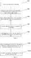
- FIG. 1 shows a flowchart of an intraoperative planning adjustment method for TKA according to an exemplary embodiment of the present application.
- the intraoperative planning adjustment method for TKA comprises the following steps.
- preoperative planning data is imported.
- the preoperative planning data includes prosthesis data (such as joint prosthesis model) and a preliminary osteotomy plan formed through preoperative planning.
- a 3D model of the skeletal anatomy of the surgical object is generally generated from the computer tomography (CT) or magnetic resonance imaging (MRI) image data set of the surgical object, the preoperative coordinate system is determined and the image is corrected.
- a set of 3D models of joint prosthesis is loaded into the system, surgeons are allowed to place the desired joint prosthesis model into the 3D model of the bone anatomy, the position and direction of the joint prosthesis are adjusted to realize the preoperative optimal cooperation of joint prosthesis and bones.
- the prosthesis data includes three-dimensional model data of the joint prosthesis and its corresponding spatial definition in human anatomy.
- the preliminary osteotomy plan comprises the spatial position and osteotomy plane matching the planned joint prosthesis and generated by the three-dimensional planning of the joint prosthesis and the patient's bone model.
- image registration is performed between the preoperative planning image and the surface contour of the knee joint of the surgical object.
- the purpose of registration is to establish a match between the virtual 3D model and the real bones.
- the specific registration method can be to use a structured light navigator to take multiple points on the surface of the bone with a probe, and to calculate the center of the femoral head by rotating the femur.
- This solution uses a point cloud registration algorithm to achieve precise registration of the joint surfaces of the femur and tibia respectively. For example, a rough registration of six marking points can be performed first, then a fine registration of multiple points, and finally the registration result can be verified.
- the dynamic-interval force line data of the knee joint at a continuous flexion-extension angle is obtained.
- the acquiring the dynamic spacing force line data of the knee joint at a continuous flexion-extension angle comprises acquiring the motion trajectory information of the knee joint during the continuous flexion-extension of the lower limb; and calculating the gap and the force line angle at the continuous flexion-extension angle of the lower limb.
- the acquisition of the movement trajectory information of the knee joint during the continuous flexion-extension of the lower limb comprises setting tracers on the femur and tibia of the knee joint; and during the continuous flexion-extension of the lower limb, continuously tracking the tracers by an optical camera, and acquiring and recording the motion trajectory information of the knee joint.
- the gap includes a first gap and a second gap.
- the first gap is the minimum gap between the outer surface of the medial femoral condyle of the prosthesis and the tibial osteotomy plane.
- the second gap is the minimum gap between the outer surface of the lateral femoral condyle of the prosthesis and the tibial osteotomy plane.
- the force line angle is the angle between the femoral mechanical axis and the tibial mechanical axis.
- the dynamic spacing force line data graph is displayed visually.
- the dynamic spacing force line data graph includes a first gap graph, a second gap graph, and a force line angle change graph.
- the first gap graph is drawn by taking the flexion-extension angle of the lower limb as the ordinate and the first gap as the abscissa.
- the second gap graph is drawn by taking the flexion-extension angle of the lower limb as the ordinate and the second gap as the abscissa.
- the force line angle change graph is drawn by taking the flexion-extension angle of the lower limb as the ordinate and the force line angle as the abscissa.
- the recorded gap and force line data of the lower limb at a certain reachable flexion-extension angle can be stored as a one-time spacing force line data graph, and can be recorded and stored multiple times.
- the gaps and force line data can also be recorded and stored multiple times.
- the prosthesis planing is adjusted according to the visual display of the dynamic spacing force line data.
- interactively editable prosthesis position information is provided, including varus/valgus angle, external/internal rotation angle, anterior/posterior slope angle, vertical translation distance, and lateral translation distance.
- the surgeon can interactively adjust the position of the prosthesis through a visual display interface. According to the received position adjustment information of the prosthesis, the gap and force line will be recalculated and the dynamic spacing force line data graph will be refreshed.
- the visual display provides the surgeon with an intuitive and clear planning adjustment result.
- the surgeon can continuously adjust the prosthesis position information according to the visual display of the dynamic spacing force line data graph until the content displayed by the dynamic spacing force line data graph reaches the requirement of the surgeon.
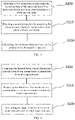
- FIG. 2 shows a flowchart of gap calculation according to an exemplary embodiment of the present application.
- a method for calculating the gap comprises the following steps.
- the lowest point of the curved surface of the outer surface of the prosthetic femur on the neutral vertical axis of the human body is used.
- the outer surface of the prosthetic femoral medial condyle is used.
- the outer surface of the prosthetic femoral lateral condyle is used.
- the distance from the lowest point to the tibial osteotomy plane is calculated.
- the calculated distance is the distance from a three-dimensional space surface to another three-dimensional space plane, which can more truly reflect the motion state of the knee joint.
- FIG. 3 shows a flowchart of gap calculation according to another exemplary embodiment of the present application.
- another method for calculating the gap comprises the following steps.
- a first projection is obtained by projecting the curved surface of the outer surface of the prosthetic femur on the neutral coronal plane of the human body.
- the outer surface of the prosthetic femoral medial condyle is used.
- the outer surface of the prosthetic femoral lateral condyle is used.
- a second projection is obtained by projecting the tibia osteotomy plane on the neutral coronal plane of the human body.
- the minimum distance from the first projection to the second projection is calculated.
- the calculated gap is the distance from a two-dimensional plane to another two-dimensional plane.
- FIG. 4 shows a flowchart of calculating a force line angle according to an exemplary embodiment of the present application.
- a method for calculating the force line angle comprises the following steps.
- the femoral mechanical axis is projected on the neutral coronal plane of the human body to obtain the femoral projection axis.
- the tibial mechanical axis is projected on the neutral coronal plane of the human body to obtain the tibial projection axis.
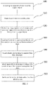
- FIG. 5 shows a flowchart of an intraoperative planning adjustment method for TKA according to another exemplary embodiment of the present application.
- the intraoperative planning adjustment method for TKA further comprises the following steps.
- the lower limb force line of the surgical object is obtained.
- the actual lower limb force line of the surgical object is an important reference standard for the surgeon in the planning adjustment process.
- To obtain the true force line during the operation by obtaining the center of the femoral head and marking the bony markers, the center of the femoral condyle, the center of the tibial plateau, and the center of the ankle point can be determined, so as to obtain the true lower limb force line.
- the intraoperative prosthesis planning data is saved and/or output.
- the adjusted prosthesis planning data can be saved locally or output to an actuator.
- the intraoperative planning adjustment method provided in the present application can be teratively performed many times.
- the first intraoperative planning adjustment is made through the first recorded lower limb movement trajectory information, the planning results are output to the actuator, and the actuator performs the first osteotomy.
- the lower limb movement trajectory information is recorded for the second time, and the second intraoperative planning adjustment and the second osteotomy are performed. The same operation is performed on and on, until the osteotomy effect satisfactory to the surgeon is achieved.
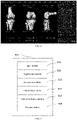
- FIG. 6 shows a photo of a dynamic spacing force line data graph according to an exemplary embodiment of the present application.
- the visual dynamic spacing force line data graph 600 includes: a first gap curve 610, a second gap curve 620, and a force line angle change curve 630.
- the ordinates of the first gap curve 610, the second gap curve 620, and the force line angle change curve 630 are all lower limb flexion-extension angles.
- the reachable flexion-extension angle of the human knee joint ranges from -10° to 130°.
- the first gap curve 610 takes the first gap as the first abscissa
- the second gap curve 620 takes the second gap as the second abscissa.
- the first abscissa and the second abscissa share an origin to form a gap abscissa.
- the gap abscissa may be set below the dynamic spacing force line data graph, and extend positively to the left and right sides, and the first gap curve and the second gap curve are respectively set on both sides of the origin of the gap abscissa.
- the force line angle change curve 630 takes the force line angle as the abscissa.
- the force line angle abscissa can be set at the top part of the dynamic spacing force line data graph.
- the origin is in the middle position, one side of the origin is positive and the other side is negative.
- the force line angle is controlled between -3° and 3°, and the postoperative soft tissue can achieve a better balance.
- FIG. 7 shows a first photo of the interactive interface of the intraoperative planning adjustment method for TKA according to an exemplary embodiment of the present application.
- the interactive interface includes a left part and a right part.
- the view of the left part includes three knee joint views, which respectively represent the knee joint and prosthesis state when the flexion-extension angles are 0°, 45°, and 90°.
- the left part also provides editable prosthesis data parameters for the surgeon to adjust the planning. Specifically, the parameters include:
- Varus/valgus angle the varus/valgus angle (Varus/Valgus) between the femur/tibia prosthesis and bone.
- the degree of the Varus angle is displayed. If the angle is 0°, it is displayed as Varus/Valgus 0°.
- the degree of the Valgus angle is displayed.
- Internal/external rotation angle the internal/external rotation angle (External/Internal) of the femur/tibia prosthesis relative to the bone.
- the degree of external rotation (External) is displayed. If the degree of external rotation is 0°, it is displayed as External/Internal 0°.
- the degree of internal rotation (Internal) is displayed.
- Planned Varus/Valgus The planned force line angle of the lower limb at the currently selected flexion-extension angle.
- the right part mainly includes the dynamic spacing force line data graph as shown in FIG. 6 , which will not be repeated here.
- FIG. 8 shows a second photo of the interactive interface of the intraoperative planning adjustment method for TKA according to an exemplary embodiment of the present application.
- the intraoperative planning adjustment method for TKA provided in the present application not only provides visual data display for the surgeon, but also provides the surgeon with interactive planning adjustment.
- the surgeon adjusts the prosthesis parameter information in the left part of FIG. 8 , such as adjusting the varus angle, internal and external rotation angle, etc.
- the first gap, the second gap, and the force line angle are recalculated by the methods shown in FIGs. 2 to 4 , and the adjusted dynamic spacing force line data graph is displayed on the right side of the interactive interface in real time.
- FIG. 8 it is the interactive interface after the prosthesis parameters are adjusted.
- FIG. 9 shows a block diagram of an intraoperative planning adjustment device for TKA according to an exemplary embodiment of the present application.
- an intraoperative planning adjustment apparatus 900 for TKA comprising an input module 910, a registration module 920, an acquisition module 930, a calculation module 940, an interactive display module 950, and a storage module 960, wherein:
- FIG. 10 shows a block diagram of an electronic device according to an exemplary embodiment of the present application.
- the electronic device 800 according to this embodiment of the present application will be described below with reference to FIG. 10 .
- the electronic device 800 shown in FIG. 8 is only an example, and in no way limits the function and scope of use of the embodiments of the present application.
- the electronic device 800 is represented in the form of a general-purpose computing device.
- the components of the computer system/server 800 may include but are not limited to: at least one processing unit 810, at least one storage unit 820, and a bus 830 connecting different system components (including the storage unit 820 and the processing unit 810).
- the storage unit 820 stores program codes which can be executed by the processing unit 810, so that the processing unit 810 executes the methods described in the present specification according to the embodiments of the present application.
- the storage unit 820 may include a readable medium in the form of a volatile storage unit, such as a random access storage unit (RAM) 8201 and/or a cache storage unit 8202, and may further include a read-only storage unit (ROM) 8203.
- RAM random access storage unit
- ROM read-only storage unit
- the storage unit 820 may also include a program/utility tool 8204 having a set of (at least one) program module 8205.
- program module 8205 includes but is not limited to: an operating system, one or more application programs, other program modules, and program data, Each of these examples or some combinations thereof may include the implementation of a network environment.
- the bus 830 may represent one or more of several types of bus structures, including a storage bus or a memory controller, a peripheral bus, a graphic acceleration port, a processing unit, or a local bus using any of a variety of bus architectures.
- the electronic device 800 may also communicate with one or more external devices 8001 (such as touch screens, keyboards, pointing devices, and Bluetooth devices), and may also communicate with one or more devices that enable a user to interact with the electronic device 800, and/ or communicate with any device (such as a router and a modem) that enables the electronic device 800 to communicate with one or more other computing devices. This communication can be made via an input/output (I/O) interface 850.
- the electronic device 800 may also communicate with one or more networks (e.g., a local area network (LAN), a wide area network (WAN), and/or a public network, such as the Internet) via a network adapter 860.
- the network adapter 860 may communicate with other modules of the electronic device 800 via the bus 830.
- the present application further provides a computer-readable medium, having a computer program stored thereon, and the program implements the steps of the foregoing method when executed by a processor.
- the intraoperative planning adjustment method allows the surgeon to adjust the position of the joint prosthesis and an osteotomy plan by operating the joint prosthesis to conduct up and down, left and right translation, and clockwise and counterclockwise rotation at the reachable flexion-extension angle of the lower limb of the surgical object.
- the dynamic spacing force line data graph provides the surgeon with an intuitive and flexible planning basis, and effectively improves the postoperative soft tissue balance.
Landscapes
- Health & Medical Sciences (AREA)
- Surgery (AREA)
- Engineering & Computer Science (AREA)
- Life Sciences & Earth Sciences (AREA)
- Medical Informatics (AREA)
- Robotics (AREA)
- Biomedical Technology (AREA)
- Heart & Thoracic Surgery (AREA)
- Nuclear Medicine, Radiotherapy & Molecular Imaging (AREA)
- Molecular Biology (AREA)
- Animal Behavior & Ethology (AREA)
- General Health & Medical Sciences (AREA)
- Public Health (AREA)
- Veterinary Medicine (AREA)
- Prostheses (AREA)
- Surgical Instruments (AREA)
Applications Claiming Priority (2)
| Application Number | Priority Date | Filing Date | Title |
|---|---|---|---|
| CN202010072017.3A CN111249002B (zh) | 2020-01-21 | 2020-01-21 | 全膝关节置换的术中规划调整方法、装置及设备 |
| PCT/CN2020/129136 WO2021147489A1 (zh) | 2020-01-21 | 2020-11-16 | 全膝关节置换的术中规划调整方法、装置及设备 |
Publications (2)
| Publication Number | Publication Date |
|---|---|
| EP4094706A1 true EP4094706A1 (de) | 2022-11-30 |
| EP4094706A4 EP4094706A4 (de) | 2024-04-03 |
Family
ID=70942759
Family Applications (1)
| Application Number | Title | Priority Date | Filing Date |
|---|---|---|---|
| EP20915392.3A Pending EP4094706A4 (de) | 2020-01-21 | 2020-11-16 | Verfahren, gerät und vorrichtung zur intraoperativen planungsanpassung einer knietotalendoprothese |
Country Status (4)
| Country | Link |
|---|---|
| US (1) | US12303205B2 (de) |
| EP (1) | EP4094706A4 (de) |
| CN (1) | CN111249002B (de) |
| WO (1) | WO2021147489A1 (de) |
Families Citing this family (16)
| Publication number | Priority date | Publication date | Assignee | Title |
|---|---|---|---|---|
| CN111249002B (zh) | 2020-01-21 | 2021-10-08 | 北京天智航医疗科技股份有限公司 | 全膝关节置换的术中规划调整方法、装置及设备 |
| CN111345895B (zh) * | 2020-03-13 | 2021-08-20 | 北京天智航医疗科技股份有限公司 | 全膝关节置换手术机器人辅助系统、控制方法及电子设备 |
| US12343218B2 (en) * | 2020-06-18 | 2025-07-01 | Smith & Nephew, Inc. | Methods for autoregistration of arthroscopic video images to preoperative models and devices thereof |
| CN113017829B (zh) * | 2020-08-22 | 2023-08-29 | 张逸凌 | 一种基于深度学习的全膝关节置换术的术前规划方法、系统、介质和设备 |
| CN112402076B (zh) * | 2020-11-19 | 2022-03-08 | 北京积水潭医院 | 一种定位膝关节单髁置换术中假体旋转角度安全区的方法 |
| CN113633379A (zh) * | 2021-07-30 | 2021-11-12 | 天津市天津医院 | 下肢机械轴导航系统、下肢手术导航方法以及存储介质 |
| CN116269951B (zh) * | 2021-12-14 | 2025-07-29 | 北京天智航医疗科技股份有限公司 | 用于膝关节置换手术的手术上位机及膝关节置换手术系统 |
| CN116262082B (zh) * | 2021-12-14 | 2025-07-29 | 北京天智航医疗科技股份有限公司 | 用于膝关节置换手术的手术上位机及膝关节置换手术系统 |
| CN116421368A (zh) * | 2021-12-31 | 2023-07-14 | 北京天智航医疗科技股份有限公司 | 全膝关节置换术下肢力线角度的计算方法 |
| CN116549108A (zh) * | 2022-01-28 | 2023-08-08 | 北京天智航医疗科技股份有限公司 | 基于影像的目标点位置确定方法、装置、设备及存储介质 |
| CN114693602B (zh) * | 2022-03-02 | 2023-04-18 | 北京长木谷医疗科技有限公司 | 膝关节动张力平衡态评估方法及装置 |
| CN115887001B (zh) * | 2022-12-30 | 2026-04-03 | 苏州微创畅行机器人有限公司 | 术前规划方法、存储介质、产品以及手术系统 |
| CN116747016A (zh) * | 2023-06-01 | 2023-09-15 | 北京长木谷医疗科技股份有限公司 | 智能手术机器人导航定位系统及方法 |
| CN118453111B (zh) * | 2024-07-11 | 2024-09-20 | 骨圣元化机器人(深圳)有限公司 | 术中膝关节间隙调整装置和膝关节手术设备 |
| CN119856990B (zh) * | 2025-03-25 | 2025-06-03 | 北京纳通医疗科技控股有限公司 | 一种膝关节力线测量系统 |
| CN120713686B (zh) * | 2025-08-28 | 2025-11-04 | 悟通感控(北京)科技有限公司 | 膝关节置换术中的数据处理方法、介质和设备 |
Family Cites Families (8)
| Publication number | Priority date | Publication date | Assignee | Title |
|---|---|---|---|---|
| US7708741B1 (en) * | 2001-08-28 | 2010-05-04 | Marctec, Llc | Method of preparing bones for knee replacement surgery |
| US20080108912A1 (en) * | 2006-11-07 | 2008-05-08 | General Electric Company | System and method for measurement of clinical parameters of the knee for use during knee replacement surgery |
| CA2683717C (en) | 2007-04-19 | 2016-10-11 | Mako Surgical Corp. | Implant planning using captured joint motion information |
| ES2776151T3 (es) * | 2011-02-25 | 2020-07-29 | Corin Ltd | Un método implementado por ordenador para proporcionar datos de información de alineación para la alineación de un implante ortopédico para una articulación de un paciente |
| WO2016049151A1 (en) * | 2014-09-24 | 2016-03-31 | Depuy (Ireland) | Surgical planning and method |
| JP6680911B2 (ja) * | 2016-05-27 | 2020-04-15 | マコー サージカル コーポレイション | 手術システム用の術前計画及び関連する術中見当合わせ |
| CN111249002B (zh) * | 2020-01-21 | 2021-10-08 | 北京天智航医疗科技股份有限公司 | 全膝关节置换的术中规划调整方法、装置及设备 |
| CN111345895B (zh) * | 2020-03-13 | 2021-08-20 | 北京天智航医疗科技股份有限公司 | 全膝关节置换手术机器人辅助系统、控制方法及电子设备 |
-
2020
- 2020-01-21 CN CN202010072017.3A patent/CN111249002B/zh active Active
- 2020-11-16 US US17/287,438 patent/US12303205B2/en active Active
- 2020-11-16 WO PCT/CN2020/129136 patent/WO2021147489A1/zh not_active Ceased
- 2020-11-16 EP EP20915392.3A patent/EP4094706A4/de active Pending
Also Published As
| Publication number | Publication date |
|---|---|
| US12303205B2 (en) | 2025-05-20 |
| CN111249002A (zh) | 2020-06-09 |
| US20220175452A1 (en) | 2022-06-09 |
| WO2021147489A1 (zh) | 2021-07-29 |
| EP4094706A4 (de) | 2024-04-03 |
| CN111249002B (zh) | 2021-10-08 |
Similar Documents
| Publication | Publication Date | Title |
|---|---|---|
| US12303205B2 (en) | TKA intraoperative planning adjustment method, apparatus and device for TKA | |
| US12396794B2 (en) | Total knee arthroplasty robot auxiliary system, control method and electronic device | |
| US12114934B2 (en) | Automated arthroplasty planning | |
| US20260111096A1 (en) | Method and System for Planning Implant Component Position | |
| WO2023029363A1 (zh) | 一种手术机器人导航定位系统及方法 | |
| CN108478250A (zh) | 全膝关节置换术的股骨定位方法、个体化截骨导板及假体 | |
| CN114305697B (zh) | 一种关节置换手术机器人的控制方法 | |
| CN118453111B (zh) | 术中膝关节间隙调整装置和膝关节手术设备 | |
| CN115005987A (zh) | 髋关节翻修手术中骨盆配准的方法及系统 | |
| WO2025222718A1 (zh) | 基于双平面影像的全膝关节置换术前规划方法及系统 | |
| WO2025077722A1 (zh) | 骨科手术机器人系统以及骨科手术机器人操作方法 | |
| CN119679516A (zh) | 肩关节置换手术导航系统及方法 | |
| CN115607286B (zh) | 基于双目标定的膝关节置换手术导航方法、系统及设备 | |
| CN119700293A (zh) | 髋关节垫块假体的术前规划方法及规划设备 | |
| CN120154416A (zh) | 术前规划方法及医疗设备 | |
| CN115300102B (zh) | 一种用于确定髌骨切除平面的系统和方法 | |
| CN118557286A (zh) | 一种膝关节置换导航方法、装置、电子设备及存储介质 | |
| HK40118807B (zh) | 髋关节垫块假体的术前规划方法及规划设备 | |
| HK40118807A (zh) | 髋关节垫块假体的术前规划方法及规划设备 | |
| CN120182160A (zh) | 截骨参数确定方法、装置和计算机设备 | |
| CN119446417A (zh) | 一种精准撑开角度规划方法、装置和存储介质 | |
| CN117017484A (zh) | 一种椎弓根螺钉通道自动规划方法、电子设备及存储介质 | |
| Doi et al. | Volume manipulation using cut and paste operations and its apllications | |
| Brockmann et al. | Evaluation of applicability and accuracy of different surface scanning systems in medicine | |
| Kovacs et al. | Three-dimensional computer-assisted intuitive breast surgery planning |
Legal Events
| Date | Code | Title | Description |
|---|---|---|---|
| STAA | Information on the status of an ep patent application or granted ep patent |
Free format text: STATUS: THE INTERNATIONAL PUBLICATION HAS BEEN MADE |
|
| PUAI | Public reference made under article 153(3) epc to a published international application that has entered the european phase |
Free format text: ORIGINAL CODE: 0009012 |
|
| STAA | Information on the status of an ep patent application or granted ep patent |
Free format text: STATUS: REQUEST FOR EXAMINATION WAS MADE |
|
| 17P | Request for examination filed |
Effective date: 20220120 |
|
| AK | Designated contracting states |
Kind code of ref document: A1 Designated state(s): AL AT BE BG CH CY CZ DE DK EE ES FI FR GB GR HR HU IE IS IT LI LT LU LV MC MK MT NL NO PL PT RO RS SE SI SK SM TR |
|
| DAV | Request for validation of the european patent (deleted) | ||
| DAX | Request for extension of the european patent (deleted) | ||
| A4 | Supplementary search report drawn up and despatched |
Effective date: 20240304 |
|
| RIC1 | Information provided on ipc code assigned before grant |
Ipc: A61B 34/20 20160101ALI20240227BHEP Ipc: A61B 34/10 20160101AFI20240227BHEP |
|
| STAA | Information on the status of an ep patent application or granted ep patent |
Free format text: STATUS: EXAMINATION IS IN PROGRESS |
|
| 17Q | First examination report despatched |
Effective date: 20260326 |