EP4094790B1 - Kassette, arzneimittelinjektionsvorrichtung und arzneimittelinjektionssystem - Google Patents
Kassette, arzneimittelinjektionsvorrichtung und arzneimittelinjektionssystem Download PDFInfo
- Publication number
- EP4094790B1 EP4094790B1 EP21743648.4A EP21743648A EP4094790B1 EP 4094790 B1 EP4094790 B1 EP 4094790B1 EP 21743648 A EP21743648 A EP 21743648A EP 4094790 B1 EP4094790 B1 EP 4094790B1
- Authority
- EP
- European Patent Office
- Prior art keywords
- cassette
- cap
- piston
- cartridge
- drug
- Prior art date
- Legal status (The legal status is an assumption and is not a legal conclusion. Google has not performed a legal analysis and makes no representation as to the accuracy of the status listed.)
- Active
Links
Images









Classifications
-
- A—HUMAN NECESSITIES
- A61—MEDICAL OR VETERINARY SCIENCE; HYGIENE
- A61M—DEVICES FOR INTRODUCING MEDIA INTO, OR ONTO, THE BODY; DEVICES FOR TRANSDUCING BODY MEDIA OR FOR TAKING MEDIA FROM THE BODY; DEVICES FOR PRODUCING OR ENDING SLEEP OR STUPOR
- A61M5/00—Devices for bringing media into the body in a subcutaneous, intra-vascular or intramuscular way; Accessories therefor, e.g. filling or cleaning devices, arm-rests
- A61M5/178—Syringes
- A61M5/28—Syringe ampoules or carpules, i.e. ampoules or carpules provided with a needle
- A61M5/281—Syringe ampoules or carpules, i.e. ampoules or carpules provided with a needle using emptying means to expel or eject media, e.g. pistons, deformation of the ampoule, or telescoping of the ampoule
-
- A—HUMAN NECESSITIES
- A61—MEDICAL OR VETERINARY SCIENCE; HYGIENE
- A61M—DEVICES FOR INTRODUCING MEDIA INTO, OR ONTO, THE BODY; DEVICES FOR TRANSDUCING BODY MEDIA OR FOR TAKING MEDIA FROM THE BODY; DEVICES FOR PRODUCING OR ENDING SLEEP OR STUPOR
- A61M5/00—Devices for bringing media into the body in a subcutaneous, intra-vascular or intramuscular way; Accessories therefor, e.g. filling or cleaning devices, arm-rests
- A61M5/178—Syringes
- A61M5/31—Details
- A61M5/315—Pistons; Piston-rods; Guiding, blocking or restricting the movement of the rod or piston; Appliances on the rod for facilitating dosing ; Dosing mechanisms
- A61M5/31565—Administration mechanisms, i.e. constructional features, modes of administering a dose
- A61M5/31566—Means improving security or handling thereof
- A61M5/31568—Means keeping track of the total dose administered, e.g. since the cartridge was inserted
-
- A—HUMAN NECESSITIES
- A61—MEDICAL OR VETERINARY SCIENCE; HYGIENE
- A61M—DEVICES FOR INTRODUCING MEDIA INTO, OR ONTO, THE BODY; DEVICES FOR TRANSDUCING BODY MEDIA OR FOR TAKING MEDIA FROM THE BODY; DEVICES FOR PRODUCING OR ENDING SLEEP OR STUPOR
- A61M5/00—Devices for bringing media into the body in a subcutaneous, intra-vascular or intramuscular way; Accessories therefor, e.g. filling or cleaning devices, arm-rests
- A61M5/178—Syringes
- A61M5/31—Details
- A61M5/315—Pistons; Piston-rods; Guiding, blocking or restricting the movement of the rod or piston; Appliances on the rod for facilitating dosing ; Dosing mechanisms
- A61M5/31533—Dosing mechanisms, i.e. setting a dose
- A61M5/31545—Setting modes for dosing
- A61M5/31546—Electrically operated dose setting, e.g. input via touch screen or plus/minus buttons
-
- A—HUMAN NECESSITIES
- A61—MEDICAL OR VETERINARY SCIENCE; HYGIENE
- A61M—DEVICES FOR INTRODUCING MEDIA INTO, OR ONTO, THE BODY; DEVICES FOR TRANSDUCING BODY MEDIA OR FOR TAKING MEDIA FROM THE BODY; DEVICES FOR PRODUCING OR ENDING SLEEP OR STUPOR
- A61M5/00—Devices for bringing media into the body in a subcutaneous, intra-vascular or intramuscular way; Accessories therefor, e.g. filling or cleaning devices, arm-rests
- A61M5/178—Syringes
- A61M5/31—Details
- A61M5/315—Pistons; Piston-rods; Guiding, blocking or restricting the movement of the rod or piston; Appliances on the rod for facilitating dosing ; Dosing mechanisms
- A61M5/31533—Dosing mechanisms, i.e. setting a dose
- A61M5/31545—Setting modes for dosing
- A61M5/31548—Mechanically operated dose setting member
- A61M5/31556—Accuracy improving means
- A61M5/31558—Accuracy improving means using scaling up or down transmissions, e.g. gearbox
-
- A—HUMAN NECESSITIES
- A61—MEDICAL OR VETERINARY SCIENCE; HYGIENE
- A61M—DEVICES FOR INTRODUCING MEDIA INTO, OR ONTO, THE BODY; DEVICES FOR TRANSDUCING BODY MEDIA OR FOR TAKING MEDIA FROM THE BODY; DEVICES FOR PRODUCING OR ENDING SLEEP OR STUPOR
- A61M5/00—Devices for bringing media into the body in a subcutaneous, intra-vascular or intramuscular way; Accessories therefor, e.g. filling or cleaning devices, arm-rests
- A61M5/178—Syringes
- A61M5/31—Details
- A61M5/315—Pistons; Piston-rods; Guiding, blocking or restricting the movement of the rod or piston; Appliances on the rod for facilitating dosing ; Dosing mechanisms
- A61M5/31565—Administration mechanisms, i.e. constructional features, modes of administering a dose
- A61M5/31576—Constructional features or modes of drive mechanisms for piston rods
-
- A—HUMAN NECESSITIES
- A61—MEDICAL OR VETERINARY SCIENCE; HYGIENE
- A61M—DEVICES FOR INTRODUCING MEDIA INTO, OR ONTO, THE BODY; DEVICES FOR TRANSDUCING BODY MEDIA OR FOR TAKING MEDIA FROM THE BODY; DEVICES FOR PRODUCING OR ENDING SLEEP OR STUPOR
- A61M5/00—Devices for bringing media into the body in a subcutaneous, intra-vascular or intramuscular way; Accessories therefor, e.g. filling or cleaning devices, arm-rests
- A61M5/178—Syringes
- A61M5/20—Automatic syringes, e.g. with automatically actuated piston rod, with automatic needle injection, filling automatically
- A61M2005/2073—Automatic syringes, e.g. with automatically actuated piston rod, with automatic needle injection, filling automatically preventing premature release, e.g. by making use of a safety lock
- A61M2005/208—Release is possible only when device is pushed against the skin, e.g. using a trigger which is blocked or inactive when the device is not pushed against the skin
-
- A—HUMAN NECESSITIES
- A61—MEDICAL OR VETERINARY SCIENCE; HYGIENE
- A61M—DEVICES FOR INTRODUCING MEDIA INTO, OR ONTO, THE BODY; DEVICES FOR TRANSDUCING BODY MEDIA OR FOR TAKING MEDIA FROM THE BODY; DEVICES FOR PRODUCING OR ENDING SLEEP OR STUPOR
- A61M5/00—Devices for bringing media into the body in a subcutaneous, intra-vascular or intramuscular way; Accessories therefor, e.g. filling or cleaning devices, arm-rests
- A61M5/178—Syringes
- A61M5/24—Ampoule syringes, i.e. syringes with needle for use in combination with replaceable ampoules or carpules, e.g. automatic
- A61M2005/2403—Ampoule inserted into the ampoule holder
- A61M2005/2411—Ampoule inserted into the ampoule holder from the front
-
- A—HUMAN NECESSITIES
- A61—MEDICAL OR VETERINARY SCIENCE; HYGIENE
- A61M—DEVICES FOR INTRODUCING MEDIA INTO, OR ONTO, THE BODY; DEVICES FOR TRANSDUCING BODY MEDIA OR FOR TAKING MEDIA FROM THE BODY; DEVICES FOR PRODUCING OR ENDING SLEEP OR STUPOR
- A61M5/00—Devices for bringing media into the body in a subcutaneous, intra-vascular or intramuscular way; Accessories therefor, e.g. filling or cleaning devices, arm-rests
- A61M5/178—Syringes
- A61M5/24—Ampoule syringes, i.e. syringes with needle for use in combination with replaceable ampoules or carpules, e.g. automatic
- A61M2005/2418—Ampoule syringes, i.e. syringes with needle for use in combination with replaceable ampoules or carpules, e.g. automatic comprising means for damping shocks on ampoule
-
- A—HUMAN NECESSITIES
- A61—MEDICAL OR VETERINARY SCIENCE; HYGIENE
- A61M—DEVICES FOR INTRODUCING MEDIA INTO, OR ONTO, THE BODY; DEVICES FOR TRANSDUCING BODY MEDIA OR FOR TAKING MEDIA FROM THE BODY; DEVICES FOR PRODUCING OR ENDING SLEEP OR STUPOR
- A61M5/00—Devices for bringing media into the body in a subcutaneous, intra-vascular or intramuscular way; Accessories therefor, e.g. filling or cleaning devices, arm-rests
- A61M5/178—Syringes
- A61M5/24—Ampoule syringes, i.e. syringes with needle for use in combination with replaceable ampoules or carpules, e.g. automatic
- A61M2005/2477—Ampoule syringes, i.e. syringes with needle for use in combination with replaceable ampoules or carpules, e.g. automatic comprising means to reduce play of ampoule within ampoule holder, e.g. springs
-
- A—HUMAN NECESSITIES
- A61—MEDICAL OR VETERINARY SCIENCE; HYGIENE
- A61M—DEVICES FOR INTRODUCING MEDIA INTO, OR ONTO, THE BODY; DEVICES FOR TRANSDUCING BODY MEDIA OR FOR TAKING MEDIA FROM THE BODY; DEVICES FOR PRODUCING OR ENDING SLEEP OR STUPOR
- A61M5/00—Devices for bringing media into the body in a subcutaneous, intra-vascular or intramuscular way; Accessories therefor, e.g. filling or cleaning devices, arm-rests
- A61M5/178—Syringes
- A61M5/24—Ampoule syringes, i.e. syringes with needle for use in combination with replaceable ampoules or carpules, e.g. automatic
- A61M2005/2485—Ampoule holder connected to rest of syringe
- A61M2005/2496—Ampoule holder connected to rest of syringe via pivot
-
- A—HUMAN NECESSITIES
- A61—MEDICAL OR VETERINARY SCIENCE; HYGIENE
- A61M—DEVICES FOR INTRODUCING MEDIA INTO, OR ONTO, THE BODY; DEVICES FOR TRANSDUCING BODY MEDIA OR FOR TAKING MEDIA FROM THE BODY; DEVICES FOR PRODUCING OR ENDING SLEEP OR STUPOR
- A61M5/00—Devices for bringing media into the body in a subcutaneous, intra-vascular or intramuscular way; Accessories therefor, e.g. filling or cleaning devices, arm-rests
- A61M5/178—Syringes
- A61M5/31—Details
- A61M5/315—Pistons; Piston-rods; Guiding, blocking or restricting the movement of the rod or piston; Appliances on the rod for facilitating dosing ; Dosing mechanisms
- A61M5/31565—Administration mechanisms, i.e. constructional features, modes of administering a dose
- A61M5/31576—Constructional features or modes of drive mechanisms for piston rods
- A61M2005/31588—Constructional features or modes of drive mechanisms for piston rods electrically driven
-
- A—HUMAN NECESSITIES
- A61—MEDICAL OR VETERINARY SCIENCE; HYGIENE
- A61M—DEVICES FOR INTRODUCING MEDIA INTO, OR ONTO, THE BODY; DEVICES FOR TRANSDUCING BODY MEDIA OR FOR TAKING MEDIA FROM THE BODY; DEVICES FOR PRODUCING OR ENDING SLEEP OR STUPOR
- A61M2205/00—General characteristics of the apparatus
- A61M2205/13—General characteristics of the apparatus with means for the detection of operative contact with patient, e.g. lip sensor
-
- A—HUMAN NECESSITIES
- A61—MEDICAL OR VETERINARY SCIENCE; HYGIENE
- A61M—DEVICES FOR INTRODUCING MEDIA INTO, OR ONTO, THE BODY; DEVICES FOR TRANSDUCING BODY MEDIA OR FOR TAKING MEDIA FROM THE BODY; DEVICES FOR PRODUCING OR ENDING SLEEP OR STUPOR
- A61M2205/00—General characteristics of the apparatus
- A61M2205/33—Controlling, regulating or measuring
- A61M2205/332—Force measuring means
-
- A—HUMAN NECESSITIES
- A61—MEDICAL OR VETERINARY SCIENCE; HYGIENE
- A61M—DEVICES FOR INTRODUCING MEDIA INTO, OR ONTO, THE BODY; DEVICES FOR TRANSDUCING BODY MEDIA OR FOR TAKING MEDIA FROM THE BODY; DEVICES FOR PRODUCING OR ENDING SLEEP OR STUPOR
- A61M2205/00—General characteristics of the apparatus
- A61M2205/35—Communication
- A61M2205/3546—Range
- A61M2205/3561—Range local, e.g. within room or hospital
-
- A—HUMAN NECESSITIES
- A61—MEDICAL OR VETERINARY SCIENCE; HYGIENE
- A61M—DEVICES FOR INTRODUCING MEDIA INTO, OR ONTO, THE BODY; DEVICES FOR TRANSDUCING BODY MEDIA OR FOR TAKING MEDIA FROM THE BODY; DEVICES FOR PRODUCING OR ENDING SLEEP OR STUPOR
- A61M5/00—Devices for bringing media into the body in a subcutaneous, intra-vascular or intramuscular way; Accessories therefor, e.g. filling or cleaning devices, arm-rests
- A61M5/14—Infusion devices, e.g. infusing by gravity; Blood infusion; Accessories therefor
- A61M5/142—Pressure infusion, e.g. using pumps
- A61M5/145—Pressure infusion, e.g. using pumps using pressurised reservoirs, e.g. pressurised by means of pistons
- A61M5/1452—Pressure infusion, e.g. using pumps using pressurised reservoirs, e.g. pressurised by means of pistons pressurised by means of pistons
- A61M5/14566—Pressure infusion, e.g. using pumps using pressurised reservoirs, e.g. pressurised by means of pistons pressurised by means of pistons with a replaceable reservoir for receiving a piston rod of the pump
Definitions
- the present application relates to a cassette for accommodating a medical drug cartridge, a drug injection device, and a drug injection system.
- Patent Document 2 describes a pharmaceutical cartridge holding unit which holds a pharmaceutical-filled cartridge and is mounted to a pharmaceutical injection device main body, where the pharmaceutical cartridge holding unit is configured to entail less work in the mounting or storing of the pharmaceutical cartridge, as well as a pharmaceutical injection device equipped with this unit.
- a drug cartridge may contain an amount of drug to be separately injected over a plurality of times.
- the present application provides a cassette, a drug injection device, and a drug injection system which support such drug cartridges and which permit appropriate management.
- a cassette to be loaded to a drug injection device comprising: a cartridge holder including a first end at which an injection needle is attachable/detachable, a second end having a holder opening, and a holder columnar space being located between the first end and the second end and capable of accommodating a drug cartridge
- the drug cartridge includes: a cylinder including a first end at which the injection needle is insertable/extractable, a second end at which a cylinder opening is located, and a cylinder columnar space located between the first end and the second end; a drug placed in the cylinder columnar space; and a gasket being placed in the cylinder columnar space and capable of moving along a longitudinal direction of the cylinder columnar space; a cassette cap being supported in the neighborhood of the second end of the cartridge holder so as to be capable of opening and closing the holder opening, the cassette cap including a first end having a cap opening that is opposed to the holder opening, a second end having a piston insertion
- the cassette cap In an open state, the cassette cap allows the drug cartridge to be movable into and out of the holder columnar space of the cartridge holder, and, in a closed state, the cassette cap closes the holder opening to disallow the drug cartridge to be removed while allowing the gasket of the drug cartridge inserted into the holder columnar space to be exposed in the piston insertion opening; and a locking mechanism being located in the cap columnar space of the cassette cap and at least including a rotation lock unit that is supported so as to be capable of pivoting around an axis of the cap columnar space, wherein, the rotation lock unit has a shape that engages with a piston of the drug injection device for moving the gasket of the drug cartridge; and, while the drug cartridge is inserted in the cartridge holder and the cassette cap is in a closed state, the rotation lock unit pivots between a lock position for disallowing the cassette cap to open and an unlock position for allowing the cassette cap to open.
- a drug injection device that permits appropriate management is provided.
- a drug cartridge contains an amount of drug that would correspond to a plurality of shots
- the cassette is configured in such a manner that an unfinished drug cartridge (i.e., with some drug left therein) can be removed therefrom by the user
- the removed unfinished drug cartridge may be inadvertently thrown away or lost, or the user may use a new drug cartridge while forgetting about the unfinished drug cartridge, for example.
- the drug injection device stores the remaining amount in the unfinished drug cartridge and keeps the piston at a position that is adapted to the remaining amount in the drug cartridge
- exchanging the drug cartridge may result in a situation where the position of the piston and the amount of remaining drug in the drug cartridge may not properly correspond, such that the drug injection device cannot properly inject the drug.
- the drug injection device may be configured so that the amount of remaining drug in the drug cartridge that has been inserted in the cassette or the gasket position is detected in controlling the piston. In this case, however, preparations for the injection are not complete until the piston is retracted prior to loading the cassette into the drug injection device, the position of the gasket of the drug cartridge in the loaded cassette is detected, and the piston is moved forward to the detected position. In other words, it takes time before the drug injection device becomes usable.
- a drug injection device comprising:
- the drug injection device of Item 15 wherein the piston includes the leading end portion and a main body connected to the leading end portion, an outer edge of a projected shape of the main body as projected on a plane perpendicular to the axis of the piston is locate inward of an outer edge of a projected shape of the leading end portion.
- the drug injection device of Item 15 or 16, wherein, the piston driving mechanism includes:
- the piston driving mechanism further includes:
- the drug injection device of Item 20 wherein, as the drive rod rotates while the driving bump is inserted in the helical groove of the first guide, the piston causes the rotation lock unit of the cassette to pivot between the lock position and the unlock position.
- a drug injection system comprising:
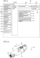
- the cassette 100 has a holder columnar space 110c in which a drug cartridge 10 can be accommodated.
- the drug cartridge 10 is not shown in FIG. 1A and FIG. 1B because it is accommodated in the holder columnar space 110c.
- the cassette 100 has a first end 100a to/from which an injection needle 21 can be attached or detached.
- the injection needle 21 is disposable, and may be treated separately, e.g., as a needle unit 20, from the cassette 100 when not in use.
- the drug injection device 200 On the surface of the outer housing 201, the drug injection device 200 has a power button 255, a selection button 256, an OK button 257, an injection button 258, an ejection lever 209, and a display section 259.
- the power button 255 is pressed to activate the drug injection device 200, in response to which the display section 259 displays a procedure for manipulating the drug injection device 200, information on the drug in the drug cartridge 10 within the loaded cassette 100, injection history, and the like.
- the cassette 100 is loaded to the drug injection device 200. While remaining in the needle unit 20, the interconnecting section 23 of the injection needle 21 is mounted to the first end 100a, and then the needle case 25 and the needle cap 24 are removed. In this state, the needle 22 is exposed, such that the tip end of the needle 22 protrudes from the skin abutment surface 201b of the outer housing 201. After the selection button 256 and the OK button 257 are pressed as appropriate to determine the operation of the drug injection device 200, a drug injecting operation is performed.
- the drug injection device 200 according to the present embodiment is a semi-automatic type, such that needle insertion and needle extraction are performed manually, i.e., by the operator.
- the injection needle 21 become inserted into the skin to a predetermined depth. Then, as the injection button 258 is pressed, a predetermined amount of drug is injected from the drug cartridge 10.
- the operator releases the drug injection device 200 from the skin, and the injection needle 21 becomes pulled out of the skin. Thereafter, the ejection lever 209 is manipulated so as to eject the cassette 100 from the drug injection device 200.
- the drug injection device 200 includes: a control section 251 including an arithmetic unit such as a CPU; a rechargeable battery 253 as a power source; a recharging section 252 for recharging the rechargeable battery 253; a memory 254 storing a computer program, data, etc.; and a clock 261.
- the control section 251 and the memory 254 constitute a control device 280, such that the control section 251 reads a program that is stored in the memory 254 and controls the component elements shown in FIG. 2 in accordance with the procedures in the computer program.
- the procedures in the computer program will be illustrated in the following description and flowcharts given in the attached drawings.
- the drug injection device 200 may further include a buzzer 260 to alarm the operator with sounds.
- the drug injection device 200 further includes an injection motor driver 263, an injection motor 264, and an encoder 265.
- the injection motor driver 263, the injection motor 264, and the encoder 265 constitute parts of a piston driving mechanism, as will be described below.
- the drug injection device 200 includes various detectors to detect the statuses of various elements of the drug injection device 200.
- the drug injection device 200 includes a piston origin detector 271, a cassette loading detector 272, a cassette retention detector 273, an ejection lever detector 274, and a skin abutment detection sensor 275.
- the drug injection device 200 may further include a communication section 262.
- the communication section 262 may perform exchange of information with the exterior via infrared communication or wireless communication, etc., for example.
- the communication section 262 may be a transmitter/receiver that utilizes a short-range wireless communication standard, e.g., BLE (Bluetooth Low Energy; Bluetooth is a registered trademark).
- BLE Bluetooth Low Energy
- the operator may cause the time of using the drug injection device 200, the kind of drug, the injected amount, and the like to be stored to the memory 254 during use, and by using the communication section 262, transmit such information to an external device, e.g., a mobile device such as a smartphone or a tablet terminal, or a dedicated device for managing the drug injection device 200, at a predetermined timing.
- an external device e.g., a mobile device such as a smartphone or a tablet terminal, or a dedicated device for managing the drug injection device 200, at a predetermined timing.
- FIG. 3A is a perspective view showing the cassette 100 accommodating the drug cartridge 10; and FIG. 3B is a perspective view showing a state where the drug cartridge 10 has been removed from the cassette 100.
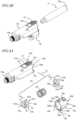
- FIG. 4A is an exploded perspective view of the cassette 100; and FIG. 4B and FIG. 4C are unit-by-unit exploded perspective views of the cassette 100 as viewed in two directions.
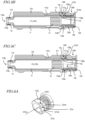
- FIG. 5A is a side view of the cassette 100; and FIG. 5B and FIG. 5C are cross-sectional views of the cassette 100.
- the cassette cap 130 creates an open state or a closed state of the holder opening 110d of the cartridge holder 110.
- the cassette cap 130 is supported so as to be capable of opening and closing the holder opening 110d.
- the cassette cap 130 includes a first end 130a having a cap opening 130d that is opposed to the holder opening 110d; a second end 130b having a piston insertion opening 130e; and a cap columnar space 130c located between the first end 130a and the second end 130b.
- the rotation lock unit 120 is accommodated in the cap columnar space 130c.
- a button space 130f lies adjacent to the cap columnar space 130c. While the cassette cap 130 keeps the holder opening 110d of the cartridge holder 110 closed, the engaging portion 111g of the cassette button 111 is located in the button space 130f.
- the cassette cap 130 includes at least one cap bump protruding into the cap opening 130d.
- the cassette cap 130 includes cap bumps 130t1 and 130t2.
- the cap bump 130t1 and the cap bump 130t2 are located on opposite sides from each other across the center of cap opening 130d.
- the cap bump 130t1 is longer than the cap bump 130t2.
- the holder opening 110d is not covered by the cassette cap 130, so that the drug cartridge 10 is movable into and out of the holder columnar space 110c of the cartridge holder 110.
- the cassette cap 130 is closed, the holder opening 110d is covered by the cassette cap 130. Therefore, the drug cartridge 10 accommodated in the holder columnar space 110c cannot be removed from the cartridge holder 110.
- the gasket 13 of the drug cartridge 10 accommodated in the holder columnar space 110c is exposed in the piston insertion opening 130e.
- the cassette cap 130 includes an alarming aperture 130h and an engaging portion 130g located on the side surface. With a colored region 126r of the rotation lock unit 120 described below, the alarming aperture 130h constitutes an alarming section to let the operator know whether the rotation lock unit 120 is in a lock position or an unlock position.
- the engaging portion 130g is shaped so as to be capable of engaging with the engaging portion 111g of the cassette button 111. In the present embodiment, the engaging portion 130g is an opening that is capable of engaging with the hook-shaped engaging portion 111g of the cassette button 111. When the engaging portion 111g of the cassette button 111 and the engaging portion 130g of the cassette cap 130 are engaged, the cassette cap 130 cannot open.
- a cap support 130j is provided having an aperture 130i into which the shaft 131 is inserted.
- the shaft 131 inserted in the aperture 130i is supported by the holder supports 110j of the cartridge holder 110 located at both ends of the aperture 130i.
- the cassette cap 130 is supported by the cartridge holder 110 so as to be capable of pivoting around the shaft 131 as an axis.
- the cap engaging portion 130k of the cassette cap 130 is located ( FIG. 4B ).
- the rotation lock unit 120 is accommodated in the cassette cap 130, and constitutes a locking mechanism together with the cassette button 111 of the cartridge holder 110 and the engaging portion 130g of the cassette cap 130.
- the locking mechanism locks the cassette cap 130 so that the cassette cap 130 cannot be opened when the cassette cap 130 is in a closed state.
- the rotation lock unit 120 includes a cartridge stopper 123, a cassette lock-ring 125, and a spring 124 disposed between the cartridge stopper 123 and the cassette lock-ring 125.
- FIG. 6A and FIG. 6B are perspective views showing the rotation lock unit 120 as viewed from different angles.
- the cartridge stopper 123 includes a ring portion 121 having a throughhole 121c.
- the ring portion 121 includes a first end 121a and a second end 121b.
- the cartridge stopper 123 includes: an abutting surface 121f which abuts with the second end 10b of the drug cartridge 10 inserted in the cartridge holder 110; and a sloped surface 121i.
- the abutting surface 121f is perpendicular to the axis 121ca of the throughhole 121c, whereas the sloped surface 121i is tilted toward the outer periphery from the axis 121ca.
- the throughhole 121c includes a columnar space that has a cross-sectional shape corresponding to a projected shape of the leading end portion of a piston 210 of the drug injection device 200 on a plane which is perpendicular to the axis of the piston 210.
- the ring portion 121 of the cartridge stopper 123 includes a first side surface subportion 121d and a second side surface subportion 121e. In a plane perpendicular to the axis 121ca of the throughhole 121c, the shortest distance between the second side surface subportion 121e and the axis 121ca of the throughhole 121c is shorter than the shortest distance between the first side surface subportion 121d and the axis 121ca of the throughhole 121c.
- the ring portion 121 has a shape resulting from cutting a short barrel or a ring having a cross section (taken perpendicular to the axis 121ca of the throughhole 121c ) with a circular outer shape horizontally with respect to the axis 121ca, such that the removed portion defines the second side surface subportion 121e and that the remaining side surface of the barrel or ring defines the first side surface subportion 121d. Therefore, in the present embodiment, the second side surface subportion 121e is a flat surface.
- the shape of the ring portion 121 is not limited to this example, and the second side surface subportion 121e may be a curved surface.
- the ring portion 121 includes grooves 121g and 121h in the first side surface subportion 121d.
- the groove 121g and the groove 121h are each in contact with the abutting surface 121f at the first end 121a; the abutting surface 121f has no side surface; and the groove 121g and the groove 121h each have an opening also on the abutting surface 121f.
- the groove 121g is further in contact with the sloped surface 121i, the groove 121g having an opening from the abutting surface over to the sloped surface 121i.
- the end 121h1 of the groove 121h is connected to the second side surface subportion 121e.
- the width of the grooves 121g and 121h along the axis 121ca is locally narrower. Specifically, the groove 121h has a narrower width at the end 121h1 side, and a broader width at the end 121h2 side. Therefore, when the groove 121h is viewed from the abutting surface 121f (first end 121a ), the stopper bump 121ht is located near the end 121h1 outside of the abutting surface 121f.
- the groove 121g has a broader width at the end 121g1 and the end 121g2, and a narrower width in between. Therefore, when the groove 121g is viewed from the abutting surface 121f, the stopper bump 121gt is located outside of the abutting surface 121f and in between the end 121g1 and the end 121g2.
- the groove 121g preferably also has an opening in the second end 121b.
- the end 121g2 of the groove 121g is located an on opposite side from the second side surface subportion 121e, across the axis 121ca.
- the cartridge stopper 123 includes a cylindrical portion 122 that is connected to the second end 121b of the ring portion 121.
- the cylindrical portion 122 includes an internal space 122c, the internal space 122c being connected to the throughhole 121c of the ring portion 121.
- the cylindrical portion 122 includes a side surface 122s, the side surface 122s having at least one cutout that extends in parallel to the axis of the internal space 122c.
- the cylindrical portion 122 includes cutouts 122d and 122e. The cutout 122d and the cutout 122e are placed essentially symmetrical with respect to the axis of the cylindrical shape.
- the cassette lock-ring 125 includes a ring portion 126 that has a throughhole 126c. As shown in FIG. 4C , the ring portion 126 includes a first end 126a and a second end 126b, and a surface 126f that is located at the second end 126b. The surface 126f is opposed to the inner surface of the second end 130b of the cassette cap 130. On the surface 126f of the cassette cap 130, a first ring engaging portion 126g1 and a second ring engaging portion 126g2 are provided on the surface 126f of the cassette cap 130. The cap engaging portion 130k of the cassette cap 130 selectively engages with one of the first ring engaging portion 126g1 and the second ring engaging portion 126g2 of the cassette lock-ring 125.
- a colored region 126r is provided on the side surface 126s of the ring portion 126.
- a groove 126h1 and a groove 126h2 are provided on the side surface 126s.
- the groove 126h1 and the groove 126h2 each reach the first end 126a and the second end 126b, thus also having openings in the first end 126a and the second end 126b.
- the groove 126h1 and the groove 126h2 respectively correspond to the lengths of the cap bumps 130t1 and 130t2 provided in the cap opening 130d of the cassette cap 130 along the peripheral direction. In other words, the length of the groove 126h1 along the peripheral direction is greater than the length of the groove 126h2 along the peripheral direction.
- the cassette lock-ring 125 includes at least one protrusion that is connected to the first end 126a of the ring portion 126.
- the cassette lock-ring 125 includes protrusions 127d and 127e.
- the protrusions 127d and 127e have a flat strip shape, and are parallel to the axis of the throughhole 126c.
- the protrusions 127d and 127e have shapes corresponding to the cutouts 122d and 122e made in the side surface 122s of the cylindrical portion 122 of the cartridge stopper 123.
- the rotation lock unit 120 is rotated, and the cap bumps 130t1 and 130t2 are aligned with the second side surface subportion 121e of the ring portion 121 of the cartridge stopper 123 and the end 121g2 of the groove 121g.
- it is rotated by about 90° in the right direction (arrow AR2 ).
- the cap bumps 130t1 and 130t2 respectively pass along the second side surface subportion 121e and the end 121g2 of the groove 121g, whereby the rotation lock unit 120 moves into the cap columnar space 130c (arrow AR3 ).
- FIG. 9A and FIG. 9B are perspective views of the cassette cap 130 accommodating the rotation lock unit 120 in an unlocked state and a locked state, respectively.
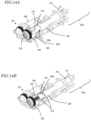
- FIG. 10A, FIG. 10B, and FIG. 10C are a top view, and side views as viewed from first end 130a and the second end 130b, of the cassette cap 130 in the unlocked state.
- FIG. 11A, FIG. 11B, and FIG. 11C are a top view, and side views as viewed from first end 130a and the second end 130b, of the cassette cap 130 in the locked state.
- the rotation lock unit 120 is placed in the unlock position.
- a region of the rotation lock unit other than the colored region 126r is located in the alarming aperture 130h. This allows the operator to recognize that the cassette cap 130 is not locked.
- the second side surface subportion 121e of the cartridge stopper 123 is opposed to the button space 130f of the cassette cap 130. Since the shortest distance between the second side surface subportion 121e and the axis is shorter than the shortest distance between the first side surface subportion 121d and the axis, a space 121ee is created between the second side surface subportion 121e and the button space 130f.
- the unit throughhole 120c of the rotation lock unit 120 is oriented in a direction such that two flat planes exist along the horizontal direction, for example.
- the cartridge stopper 123 is pushed by the drug cartridge 10 to move backward, so that the rotation lock unit 120 is capable of pivoting.
- the piston 210 rotates by about 60° as viewed from the leading end, while moving forward in the unit throughhole 120c.
- the rotation lock unit 120 rotates clockwise by 60°, whereby the rotation lock unit 120 is placed in the lock position.
- the lock position and the unlock position of the rotation lock unit 120 make an angle ⁇ around the axis of the cap columnar space, in a plane perpendicular to the axis of the cap columnar space.
- ⁇ is 60° as described above.
- the angle ⁇ may be set to any arbitrary value.
- ⁇ is not less than 30° and not more than 120°.
- the unit throughhole 120c of the rotation lock unit 120 preferably has a cross section with a rotationally symmetrical shape other than a (360/ ⁇ )-fold symmetric diagram, or have a cross section with a non-rotationally symmetrical shape.
- the first side surface subportion 121d of the cartridge stopper 123 is now opposed to the button space 130f of the cassette cap 130.
- the rotation lock unit 120 when the rotation lock unit 120 is in the lock position, the surface 126f of the cassette lock-ring 125 is urged toward the inner surface 130m of the second end 130b of the cassette cap 130, and the second ring engaging portion 126g2 of the surface 126f engages with the cap engaging portion 130k of the cassette cap 130 on the inner surface 130m. Therefore, even if the cassette 100 is subjected to external vibrations or the like in this state, the rotation lock unit 120 is kept from rotating.
- the drug cartridge 10 contains an amount of drug that would correspond to a plurality of shots
- an unfinished cassette 100 i.e., with some drug left therein
- the drug injection device does not retract the piston 210, so that injection can be performed without taking time in the next instance the unfinished cassette is loaded to the drug injection device.
- any cassette 100 that fails to have a drug cartridge accommodated therein or has an unused drug cartridge 10 accommodate therein cannot be properly loaded to the drug injection device 200.
- the rotation lock unit 120 is in the unlock position and the orientation of the cross-sectional shape of the unit throughhole 120c differs from that in the lock position, so that the piston 210 cannot be inserted in the unit throughhole 120c of the cassette cap 130.
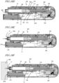
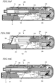
- the drug injection device 200 includes the piston 210 and a piston driving mechanism 220.
- the drug injection device 200 further includes an inner housing 202 that supports the piston driving mechanism 220.
- the outer housing 201 and the inner housing 202 constitute a housing for drug injection device 200.
- the piston 210 in a state where the cassette 100 is accommodated in the cassette space 201c, the piston 210 is able to move forward and backward along the axial direction of the drug cartridge 10 loaded in the cassette 100, and to axially rotate. As the piston 210 moves forward, abuts with the gasket 13 of the drug cartridge 10, and pushes in the gasket 13, the drug 14 can be discharged from the injection needle 21.
- the rotation lock unit 120 of the cassette cap 130 is pivoted between the lock position and the unlock position, whereby the cassette cap 130 is locked or unlocked.
- the piston driving mechanism 220 drives the piston 210 in a direction of moving forward or moving backward, and also axially rotates the piston 210.
- the piston 210 includes the leading end portion 211 and a main body 212 that is connected to the leading end portion.
- the leading end portion 211 is located near the first end 210a.
- the leading end portion 211 has an I-cut shape resulting from cutting a geometric cylinder at two parallel planes extending along the axis.
- FIG. 16A is a front view of the piston 210 as viewed from the first end 210a, in which: the left side shows a state where the piston 210 is in the initial position and is insertable in the rotation lock unit 120 (of the cassette 100 loaded in the drug injection device 200 ) being in the unlock position; and the right side shows a state where the piston 210 is insertable in the rotation lock unit 120 being in the lock position.
- the outer edge of a projected shape of the main body 212 on a plane perpendicular to the axis is located inward of the outer edge of a projected shape of the leading end portion 211. Therefore, if the leading end portion 211 is insertable in the unit throughhole 120c of the cassette 100 loaded in the drug injection device 200 in either the unlock position or the lock position, the main body can also pass through the unit throughhole 120c, and therefore, as the piston 210 moves forward, it abuts with the gasket 13 of the drug cartridge 10 being accommodated in the cassette 100, thus moving forward the gasket 13.
- the unit throughhole 120c has a cross section with a rotationally symmetrical shape other than (360/ ⁇ )-fold symmetric, or a non-rotationally symmetrical shape.
- the encoder 265 On the shaft of the injection motor 264, the encoder 265 is mounted as an amount-of-rotation detector, the encoder 265 detecting the amount of rotation (number of revolutions) of the injection motor 264.
- the gearbox 221 includes at least one gear mounted on the shaft of the injection motor 264.
- the gearbox 221 may include two or more gears in order to reduce the rotational speed of the injection motor 264.
- the drive gear 222 meshes with the gear(s) in the gearbox 221, and is rotatably supported on the inner housing 202 via a bearing 223. A hole is made in the shaft of the drive gear 222, to which one end of the drive rod 235 is inserted and fitted.
- the drive rod 235 has the shape of a rod, with an external thread 236 formed on its side surface.
- the external thread 236 has its thread height, shape, thread pitch, etc., configured so as to mesh with the internal thread 214 provided on the piston 210.
- the piston guide 230 has a hole 230h into which the piston 210 is inserted.
- the second guides 231 are provided on the inner side surface of the hole 230h. The second guides 231 engage with the driving bumps 213 of the piston 210, thereby guiding the piston 210 so as to move forward or move backward without axially rotating.
- the second guides 231 are linear grooves extending in parallel to the axis of the hole 230h, and the ribs which are the driving bumps 213 provided on the side surface of the piston 210 are inserted therein.
- the piston guide 230 includes two second guides 231 correspondingly to the two driving bumps 213 on the piston 210.
- the piston guide 230 has a groove 230g in its side surface.
- the inner housing 202 includes a gear region 202d, the first guide 203, a piston guide region 202f, a cassette region 202h, and a ridge-shaped bump 202g.
- the drive gear 222 is placed in the gear region 202d.
- the cassette region 202h is a region defining the cassette space 201c.
- FIG. 19 is a cross-sectional view of the drug injection device 200.
- the encoder 265 is mounted on the shaft of the injection motor 264, and measures the number of revolutions of the injection motor 264.
- the piston origin detector 271 detects that the piston 210 has moved backward to the initial position, for example.
- the origin may be set at a position other than the initial position.
- the piston origin detector 271 may be a microswitch, etc., that is placed so as to be pressed by the rear end of the piston 210 when the piston 210 has moved backward to the initial position.
- the cassette loading detector 272 detects loading or ejection of the cassette 100 to or from the cassette space 201c.
- a door 205 may be provided on the case opening 201d, and the cassette loading detector 272 may be a microswitch, etc., that is pressed when the door opens.
- the cassette retention detector 273 detects that the cassette 100 is or is not load to the cassette space 201c.
- the cassette retention detector 273 may be a microswitch, etc., that is placed closed to the cassette space 201c and is pressed by the loaded cassette 100, for example.
- the ejection lever detector 274 detects that the ejection lever 209 has been manipulated.
- the ejection lever detector 274 may be a microswitch, etc., that is placed closed to the ejection lever 209 and is pressed when the ejection lever 209 has slid, for example.
- the skin abutment detection sensor 275 detects that the skin abutment surface 201b has abutted with skin.
- the skin abutment detection sensor 275 may be a touch sensor, pressure sensor, etc., that is placed on the skin abutment surface 201b, for example.
- the drug injection device 200 is compatible with a drug cartridge that contains an amount of drug to be separately injected over a plurality of times. Therefore, the control device 280 stores an administration history of each drug cartridge, i.e., the used amount or the number of administered doses of the drug, in the memory 254.
- the used amount is an amount of drug that has been used since the drug cartridge was still unused.
- the number of administered doses is a number of times that the drug cartridge has been used since it was still unused.
- an operation of the drug injection system 300 will be described, from the state where the used amount or the number of administered doses stored in the memory 254 of the control device 280 is zero.
- the piston 210 of the drug injection device 200 is in an initial position, where it has moved backward to the rear end. In this state, the drive rod 235 is almost completely inserted in the hole 210h of the piston 210. Moreover, the piston 210 is at a rotation angle that allows it to be inserted into the unit throughhole 120c in the unlock position.
- the drug injection device is activated ( S1 ) .
- the cassette 100 having the unused drug cartridge 10 placed therein is pressed against the door 205, the door 205 is opened, and the cassette 100 is inserted in the cassette space 201c within the drug injection device 200.
- the cassette loading detector 272 and the cassette retention detector 273 detect the loading and retention of the cassette 100. Because the rotation lock unit 120 of the cassette 100 is in the unlock position, the leading end portion 211 of the piston 210 is inserted in the unit throughhole 120c of the rotation lock unit 120.
- the control device 280 determines whether the used amount of the drug as stored in the memory 254 is zero or not ( S3 ). Because the used amount of the drug as stored in the memory 254 is zero (following "YES" from S3 ), the drug injection device 200 performs a locking operation of the cassette 100.
- the control device 280 causes the injection motor 264 to rotate forward, whereby the drive rod 235 rotates.
- the piston 210 is guided by the first guide 203, so as to rotate by the angle ⁇ while moving forward. While moving forward in the unit throughhole 120c of the rotation lock unit 120, the leading end portion 211 of the piston 210 rotates the rotation lock unit 120 to the lock position. As a result, the cassette cap 130 is locked ( S4 ) .
- the piston 210 further moves forward and abuts with the gasket 13 of the drug cartridge 10, whereby rotation of the injection motor 264 stops.
- the operator determines a single dosage of the drug in the drug cartridge 10 and inputs it by using the selection button 256 and the OK button 257 of the drug injection device 200 ( FIG. 1 ). At this time, the set dosage that has been input is stored to the memory 254.
- the operator mounts the injection needle 21 to the first end 100a of the cassette 100 ( S6 ).
- the control device 280 updates the used amount of the drug, and stores it to the memory 254. Moreover, it determines a remaining amount of drug in the drug cartridge 10 from the amount of drug contained in the unused drug cartridge 10 and the used amount. If the remaining amount of drug is zero or equal to or less than a predetermined amount, as will be described below, a retraction operation of the piston 210 is performed. If the remaining amount of drug is not zero, removal of the cassette is performed.
- the operator slides the ejection lever 209, and removes the cassette 100.
- the ejection lever detector 274 detects manipulation of the ejection lever 209, and the cassette loading detector 272 and the cassette retention detector 273 detect ejection of the cassette 100 ( S14 ).
- a shutdown process of causing the piston 210 to slightly move backward may be performed ( S13 ).
- the control device 280 causes the injection motor 264 to rotate backward so that the piston 210 moves backward by a predetermined amount, and stops it.
- the gasket 13 placed at the rear end of the drug cartridge 10 is kept from abutting with the piston 210 and allowing the drug to be discharged unintentionally. Since only the abutment at the time of loading may be suppressed, the piston 210 only needs to move backward by a small distance, e.g., about 1 mm.
- the cassette 100 that has been removed in this state is in a state of being locked by the rotation lock unit 120. Moreover, some drug is still left in the drug cartridge 10. Thus, the operator is kept from inadvertently opening the cassette cap 130 to remove the drug cartridge 10 with the drug left therein, and throwing it away.
- the drug injection device 200 stops ( S15 ).
- the piston 210 is at an angular position that is suitable for a locked cassette 100, the cassette 100 accommodating an unfinished drug cartridge 10 can be properly loaded to the drug injection device 200.
- the orientation of the unit throughhole 120c and the orientation of the piston 210 do not match, and therefore the cassette 100 cannot be properly loaded.
- the piston 210 has not retracted, or if at all, retracted by a small amount. Therefore, when the cassette 100 is loaded to the drug injection device 200, the piston 210 can abut with the gasket 13 without taking time. That is, not much time is needed until injection becomes possible.
- the control device 280 causes the injection motor 264 to rotate backward, and rotates the drive rod 235. As a result, the piston 210 moves backward while being guided by the second guides 231. Upon reaching the first guide 203, it further moves backward while rotating backward by the angle ⁇ .
- the rotation lock unit 120 rotates, and returns to the unlock position.
- the cassette cap 130 enters an unlocked state.
- the piston 210 moves backward, and the piston origin detector 271 detects that the piston 210 has moved backward to the initial position, upon which rotation of the injection motor 264 is stopped.
Landscapes
- Health & Medical Sciences (AREA)
- Vascular Medicine (AREA)
- Engineering & Computer Science (AREA)
- Anesthesiology (AREA)
- Biomedical Technology (AREA)
- Heart & Thoracic Surgery (AREA)
- Hematology (AREA)
- Life Sciences & Earth Sciences (AREA)
- Animal Behavior & Ethology (AREA)
- General Health & Medical Sciences (AREA)
- Public Health (AREA)
- Veterinary Medicine (AREA)
- Infusion, Injection, And Reservoir Apparatuses (AREA)
Claims (12)
- Kassette (100) zum Laden in eine Arzneimittelinjektionsvorrichtung (200, 200'), wobei die Kassette (100) umfasst:einen Kartuschenhalter (110), der ein erstes Ende (110a), an/von dem eine Injektionsnadel (21) anbringbar/lösbar ist, ein zweites Ende (110b), das eine Halteröffnung (110d) aufweist, und einen säulenförmigen Halterraum (110c) umfasst, der sich zwischen dem ersten Ende (110a) und dem zweiten Ende (110b) befindet und in der Lage ist, eine Arzneimittelkartusche (10) aufzunehmen, wobei die Arzneimittelkartusche (10) umfasst: einen Zylinder (11), der ein erstes Ende (11a), an/von dem die Injektionsnadel (21) einführbar/herausziehbar ist, ein zweites Ende (11b), an dem eine Zylinderöffnung (11d) sich befindet, und einen säulenförmigen Zylinderraum (11c) umfasst, der sich zwischen dem ersten Ende (11a) und dem zweiten Ende (11b) befindet; ein Arzneimittel (14), das in dem säulenförmigen Zylinderraum (11c) platziert ist; und eine Dichtung (13), die in dem säulenförmigen Zylinderraum (11c) platziert ist und in der Lage ist, sich entlang einer Längsrichtung des säulenförmigen Zylinderraums (11c) zu bewegen;eine Kassettenkappe (130), die derart in der Nachbarschaft des zweiten Endes (110b) des Kartuschenhalters (110) gestützt wird, dass sie in der Lage ist, die Halteröffnung (110d) zu öffnen und zu schließen, wobei die Kassettenkappe (130) ein erstes Ende (130a), das eine Kappenöffnung (130d) aufweist, das der Halteröffnung (110d) entgegengesetzt ist, ein zweites Ende (130b), das eine Kolbeneinführungsöffnung (130e) aufweist, und einen säulenförmigen Kappenraum (130c) umfasst, der sich zwischen dem ersten Ende (130a) und dem zweiten Ende (130b) befindet, wobei in einem geöffneten Zustand die Kassettenkappe (130) es der Arzneimittelkartusche (10) erlaubt, in den und aus dem säulenförmigen Halterraum (110c) des Kartuschenhalters (110) beweglich zu sein, und in einem geschlossenen Zustand die Kassettenkappe (130) die Halteröffnung (110d) schließt, um es der Arzneimittelkartusche (10) nicht zu erlauben, entfernt zu werden, während es der Dichtung (13) der Arzneimittelkartusche (10), die in den säulenförmigen Halterraum (110c) eingeführt ist, erlaubt wird, in der Kolbeneinführungsöffnung (130e) freizuliegen; undeinen Verriegelungsmechanismus, der sich in dem säulenförmigen Kappenraum (130c) der Kassettenkappe (130) befindet und mindestens eine Drehverriegelungseinheit (120) umfasst, die derart unterstützt wird, dass sie in der Lage ist, um eine Achse des säulenförmigen Kappenraums (130c) zu schwenken, wobei der Verriegelungsmechanismus ferner einen Kassettenknopf (111) umfasst, der auf dem Kartuschenhalter (110) bereitgestellt ist, um in der Lage zu sein, gedrückt zu werden; undein Paar Eingriffsabschnitte (111g, 130g), die jeweils auf dem Kassettenknopf (111) und auf der Kassettenkappe (130) bereitgestellt sind, wobei die Eingriffsabschnitte (111g, 130g) in der Lage sind, ineinanderzugreifen;wobeidie Drehverriegelungseinheit (120) eine Form aufweist, die mit einem Kolben (210) der Arzneimittelinjektionsvorrichtung (200, 200') zum Bewegen der Dichtung (13) der Arzneimittelkartusche (10) ineinandergreift und Folgendes umfasst:- ein Einheitsdurchgangsloch (120c), das eine Querschnittsform aufweist, die einer Querschnittsform eines Vorderendabschnitts (211) des Kolbens (210) senkrecht zu einer Achse des Kolbens (210) entspricht,- einen Kassettenverriegelungsring (125),- einen Kartuschenstopper (123), und- eine Feder (124), die zwischen dem Kassettenverriegelungsring (125) und dem Kartuschenstopper (123) angeordnet ist;während die Arzneimittelkartusche (10) in den Kartuschenhalter (110) eingeführt ist und die Kassettenkappe (130) sich in einem geschlossenen Zustand befindet, die Drehverriegelungseinheit (120) zwischen einer Verriegelungsposition, um es der Kassettenkappe (130) nicht zu erlauben, sich zu öffnen, und einer Entriegelungsposition schwenkt, um es der Kassettenkappe (130) zu erlauben, sich zu öffnen;wenn der Vorderendabschnitt (211) des Kolbens (210) von außen in das Einheitsdurchgangsloch (120c) der Drehverriegelungseinheit (120) eingeführt wird und der Kolben (210) sich um eine Achse des Kolbens (210) dreht, die Drehverriegelungseinheit (120) innerhalb der Kassettenkappe (130) schwenkt;wenn die Drehverriegelungseinheit (120) sich in der Entriegelungsposition befindet, der Kassettenknopf (111) drückbar ist, derart dass das Paar Eingriffsabschnitte (111g, 130g) voneinander außer Eingriff gebracht werden, während der Kassettenknopf (111) gedrückt wird;wenn die Drehverriegelungseinheit (120) sich in der Verriegelungsposition befindet, der Kassettenknopf (111) nicht drückbar ist und das Paar Eingriffsabschnitte (111g, 130g) miteinander in Eingriff sind; undder Kassettenverriegelungsring (125) und der Kartuschenstopper (123) das Einheitsdurchgangsloch (120c) auf eine einheitliche Weise bilden und in der Lage sind, sich in dem säulenförmigen Kappenraum (130c) auf eine einheitliche Weise zu drehen, und in dem säulenförmigen Kappenraum (130c) der Kassettenkappe (130) der Kartuschenstopper (123) hin zum ersten Ende (130a) der Kassettenkappe (130) gedrängt wird und der Kassettenverriegelungsring (125) durch die Feder (124) hin zum zweiten Ende (130b) der Kassettenkappe (130) gedrängt wird.
- Kassette (100) nach Anspruch 1, wobei ein projiziertes Bild des Einheitsdurchgangslochs (120c) der Drehverriegelungseinheit (120), wie auf eine Ebene senkrecht zu einer Achse davon projiziert, sich unterscheidet, wenn die Drehverriegelungseinheit (120) sich in der Verriegelungsposition befindet und wenn die Drehverriegelungseinheit (120) sich in der Entriegelungsposition befindet.
- Kassette (100) nach Anspruch 2, wobei die Drehverriegelungseinheit (120) nicht schwenkbar ist, wenn die Arzneimittelkartusche (10) nicht in den Kartuschenhalter (110) eingeführt ist und die Kassettenkappe (130) sich in einem geschlossenen Zustand befindet.
- Kassette (100) nach einem der Ansprüche 1 bis 3, ferner umfassend eine Alarmierungssektion zum Informieren, dass die Drehverriegelungseinheit (120) sich in der Verriegelungsposition und/oder der Entriegelungsposition befindet.
- Kassette (100) nach Anspruch 4, wobeidie Alarmierungssektion ein Alarmierungsloch (130h), das sich auf einer Seitenoberfläche der Kassettenkappe (130) befindet, und eine farbige Region (126r) aufweist, die auf einer Seitenoberfläche (126s) der Drehverriegelungseinheit (120) bereitgestellt ist;wenn die Drehverriegelungseinheit (120) sich in der Entriegelungsposition befindet, die farbige Region (126r) sich außerhalb des Alarmierungslochs (130h) befindet; undwenn die Drehverriegelungseinheit (120) sich in der Verriegelungsposition befindet, die farbige Region (126r) sich in dem Alarmierungsloch (130h) befindet.
- Kassette (100) nach Anspruch 5, wobeidie Kassettenkappe (130) einen Kappenhöcker (130t1, 130t2) umfasst, der in die Kappenöffnung (130d) hervorsteht;wobei der Kartuschenstopper (123) eine Stoßoberfläche (121f) zum Stoßen an das zweite Ende (10b) der Arzneimittelkartusche (10), die in den Kartuschenhalter (110) eingeführt ist, während die Kassettenkappe (130) geschlossen ist, und einen Stopperhöcker (121ht, 121gt) umfasst, der sich außerhalb der Stoßoberfläche (121f) befindet; undwenn die Arzneimittelkartusche (10) nicht in den Kartuschenhalter (110) geladen ist und die Kassettenkappe (130) geschlossen ist, der Stopperhöcker (121ht, 121gt) an den Kappenhöcker (130t1, 130t2) stößt, um Schwenken der Drehverriegelungseinheit (120) einzuschränken, und, wenn die Arzneimittelkartusche (10) in dem Kartuschenhalter (110) geladen ist und die Kassettenkappe (130) geschlossen ist, das Stoßen zwischen dem zweiten Ende (10b) der Arzneimittelkartusche (10) und der Stoßoberfläche (121f) des Kartuschenstoppers (123) den Kartuschenstopper (123) veranlasst, sich rückwärts hin zu dem zweiten Ende (130b) der Kassettenkappe (130) zu bewegen, den Stopperhöcker (121ht, 121gt) veranlasst, von dem Kartuschenhöcker (130t1, 130t2) beabstandet zu werden, und der Drehverriegelungseinheit (120) ermöglicht, zu schwenken.
- Kassette (100) nach Anspruch 6, wobeider Kartuschenstopper (123) einen ersten Seitenoberflächen-Teilabschnitt (121d) und einen zweiten Seitenoberflächen-Teilabschnitt (121e) umfasst;in einer Ebene senkrecht zur Achse des Kolbens (210) ein kürzester Abstand zwischen dem zweiten Seitenoberflächen-Teilabschnitt (121e) und der Achse des Kolbens (210) kürzer als ein kürzester Abstand zwischen dem ersten Seitenoberflächen-Teilabschnitt (121d) und der Achse des Kolbens (210) ist;wenn die Drehverriegelungseinheit (120) sich in der Verriegelungsposition befindet, das Stoßen zwischen dem ersten Seitenoberflächen-Teilabschnitt (121d) und dem Kassettenknopf (111) den Kassettenknopf (111) undrückbar hält; undwenn die Drehverriegelungseinheit (120) sich in der Entriegelungsposition befindet, der Kassettenknopf (111) drückbar ist, bis der Kassettenknopf (111) an den zweiten Seitenoberflächen-Teilabschnitt (121e) stößt.
- Kassette (100) nach Anspruch 6 oder 7, wobeider Kassettenverriegelungsring (125) und der Kartuschenstopper (123) jeweils einen Ringabschnitt (126, 121) aufweisen;die Stoßoberfläche (121f) und der Stopperhöcker (121ht, 121gt) des Kartuschenstoppers (123) sich auf dem Ringabschnitt (121) befinden;einer von dem Kassettenverriegelungsring (125) und dem Kartuschenstopper (123) mindestens einen Ausschnitt (122d, 122e) umfasst, der sich parallel zu einer Achse der Drehverriegelungseinheit (120) und einer Seitenoberfläche (122s) einer Zylinderform erstreckt, die mit dem Ringabschnitt (121) verbunden ist, und der andere mindestens einen Vorsprung (127d, 127e) umfasst, der mit dem Ringabschnitt (126) verbunden ist, wobei der mindestens eine Vorsprung (127d, 127e) eine Form aufweist, die sich parallel zur Achse der Drehverriegelungseinheit (120) erstreckt und mit dem mindestens einen Ausschnitt (122d, 122e) zusammenpasst; undwenn der mindestens eine Vorsprung (127d, 127e) in dem mindestens einen Ausschnitt (122d, 122e) eingeführt ist, der Kassettenverriegelungsring (125) und der Kartuschenstopper (123) in der Lage sind, sich in Bezug aufeinander entlang der axialen Richtung zu bewegen, derart dass die jeweiligen Ringabschnitte (126, 121) davon näher zueinander oder weiter voneinander weg gelangen.
- Kassette (100) nach Anspruch 8, wobeider Ringabschnitt (126) des Kassettenverriegelungsrings (125) einen ersten Ringeingriffsabschnitt (126g1) und einen zweiten Ringeingriffsabschnitt (126g2) umfasst, die sich auf einer Oberfläche befinden, die einer Innenoberfläche des zweiten Endes (130b) der Kassettenkappe (130) entgegengesetzt ist;auf der Innenoberfläche des zweiten Endes (130b) der Kassettenkappe (130) die Kassettenkappe (130) einen Kappeneingriffsabschnitt (130g) umfasst, der in der Lage ist, selektiv mit dem ersten Ringeingriffsabschnitt (126g1) oder dem zweiten Ringeingriffsabschnitt (126g2) ineinanderzugreifen;wenn die Drehverriegelungseinheit (120) sich in der Entriegelungsposition befindet, der Kappeneingriffsabschnitt (130g) mit dem ersten Ringeingriffsabschnitt (126g1) ineinandergreift; undwenn die Drehverriegelungseinheit (120) sich in der Verriegelungsposition befindet, der Kappeneingriffsabschnitt (130g) mit dem zweiten Ringeingriffsabschnitt (126g2) ineinandergreift.
- Kassette (100) nach einem der Ansprüche 1 bis 9, wobei ein Querschnitt des Einheitsdurchgangslochs (120c) eine I-Form aufweist.
- Kassette (100) nach einem der Ansprüche 1 bis 10, wobeidie Verriegelungsposition und die Entriegelungsposition der Drehverriegelungseinheit (120) einen Winkel α um die Achse des säulenförmigen Kappenraums (130c) in einer Ebene senkrecht zur Achse des säulenförmigen Kappenraums (130c) bilden; undein Querschnitt des Einheitsdurchgangslochs (120c) eine Rotationsymmetrie aufweist, die sich von einer (360/α)-fachen Symmetrie unterscheidet.
- Arzneimittelinjektionsvorrichtung (200, 200'), umfassend:ein Gehäuse (201, 202), das eine Gehäuseöffnung (201d) und einen Kassettenraum (201c) zum Aufnehmen mindestens eines Abschnitts der Kassette (100) nach einem der Ansprüche 1 bis 11 umfasst;einen Kolben (210), der eine Achse aufweist und in der Lage ist, sich entlang einer Richtung parallel zur Achse vorwärts und rückwärts zu bewegen und um die Achse zu drehen, wobei der Kolben (210), wenn er sich vorwärts bewegt, in der Lage ist, an die Dichtung (13) der Arzneimittelkartusche (10), die in der Kassette (100) untergebracht ist, die in dem Kassettenraum (201c) platziert ist, zu stoßen und die Dichtung (13) hineinzudrücken;einen Kolbenantriebsmechanismus (220) zum Antreiben des Kolbens (210) in einer Vorwärts- oder Rückwärtsbewegungsrichtung und zum Drehen des Kolbens (210) um die Achse; undeine Steuervorrichtung (280) zum Steuern des Kolbenantriebsmechanismus (220), wobeiwenn der Kolbenantriebsmechanismus (220) den Kolben (210) um dessen Achse dreht, der Kolben (210) die Drehverriegelungseinheit (120) der Kassette (100) dazu veranlasst, zwischen der Verriegelungsposition und der Entriegelungsposition zu schwenken.
Applications Claiming Priority (2)
| Application Number | Priority Date | Filing Date | Title |
|---|---|---|---|
| JP2020009455 | 2020-01-23 | ||
| PCT/JP2021/001095 WO2021149591A1 (ja) | 2020-01-23 | 2021-01-14 | カセット、薬剤注入装置および薬剤注入システム |
Publications (3)
| Publication Number | Publication Date |
|---|---|
| EP4094790A1 EP4094790A1 (de) | 2022-11-30 |
| EP4094790A4 EP4094790A4 (de) | 2023-06-28 |
| EP4094790B1 true EP4094790B1 (de) | 2025-07-09 |
Family
ID=76992741
Family Applications (1)
| Application Number | Title | Priority Date | Filing Date |
|---|---|---|---|
| EP21743648.4A Active EP4094790B1 (de) | 2020-01-23 | 2021-01-14 | Kassette, arzneimittelinjektionsvorrichtung und arzneimittelinjektionssystem |
Country Status (4)
| Country | Link |
|---|---|
| US (1) | US12605507B2 (de) |
| EP (1) | EP4094790B1 (de) |
| JP (1) | JP7290753B2 (de) |
| WO (1) | WO2021149591A1 (de) |
Families Citing this family (5)
| Publication number | Priority date | Publication date | Assignee | Title |
|---|---|---|---|---|
| CN107635527B (zh) | 2015-03-10 | 2021-04-23 | 里珍纳龙药品有限公司 | 无菌刺穿系统和方法 |
| IL308643B2 (en) | 2017-05-05 | 2025-02-01 | Regeneron Pharma | Auto-injector |
| JP7535194B2 (ja) * | 2021-08-31 | 2024-08-15 | Phcホールディングス株式会社 | 薬剤カートリッジ、薬剤注入装置および薬剤注入システム |
| WO2023061770A1 (en) * | 2021-10-14 | 2023-04-20 | Shl Medical Ag | A sub-assembly of a medicament delivery device cassette unit and a method of operating a medicament delivery device cassette unit comprising the sub-assembly |
| USD1007676S1 (en) | 2021-11-16 | 2023-12-12 | Regeneron Pharmaceuticals, Inc. | Wearable autoinjector |
Citations (3)
| Publication number | Priority date | Publication date | Assignee | Title |
|---|---|---|---|---|
| WO2016052117A1 (ja) * | 2014-09-30 | 2016-04-07 | パナソニックヘルスケア株式会社 | 薬剤カートリッジ保持ユニット、及びそれを備えた薬剤注入装置 |
| JP2016515406A (ja) * | 2013-03-15 | 2016-05-30 | アムゲン・インコーポレーテッド | 薬物カセット、自動注入器、および自動注入器システム |
| WO2017110590A1 (ja) * | 2015-12-24 | 2017-06-29 | パナソニックヘルスケアホールディングス株式会社 | 薬剤注入装置、カートリッジアダプタおよび薬剤注入システム |
Family Cites Families (8)
| Publication number | Priority date | Publication date | Assignee | Title |
|---|---|---|---|---|
| JP2005536300A (ja) * | 2002-08-29 | 2005-12-02 | ノボ・ノルデイスク・エー/エス | 前方格納型注入デバイス |
| WO2012032411A2 (en) * | 2010-09-07 | 2012-03-15 | Tecpharma Licensing Ag | Automatic injection device |
| HUE042822T2 (hu) | 2011-04-20 | 2019-07-29 | Amgen Inc | Automata befecskendezõ szerkezet |
| TWI539981B (zh) * | 2011-05-06 | 2016-07-01 | 賽諾菲阿凡提斯德意志有限公司 | 供藥物輸送裝置用之組件及藥物輸送裝置 |
| JP6228935B2 (ja) * | 2012-02-24 | 2017-11-08 | ノボ・ノルデイスク・エー/エス | 前側挿入式構造を有する薬物送達デバイス |
| DK2836259T3 (en) * | 2012-04-11 | 2016-09-12 | Sanofi Aventis Deutschland | CARTRIDGE HOLDER AND pen-like INJECTOR |
| WO2015086482A1 (en) * | 2013-12-11 | 2015-06-18 | Sanofi-Aventis Deutschland Gmbh | Housing of a drug delivery device |
| WO2018009509A2 (en) * | 2016-07-06 | 2018-01-11 | Quio Technologies Llc | Drug delivery assembly for cartridge-based medicaments |
-
2021
- 2021-01-14 EP EP21743648.4A patent/EP4094790B1/de active Active
- 2021-01-14 US US17/794,151 patent/US12605507B2/en active Active
- 2021-01-14 JP JP2021573113A patent/JP7290753B2/ja active Active
- 2021-01-14 WO PCT/JP2021/001095 patent/WO2021149591A1/ja not_active Ceased
Patent Citations (3)
| Publication number | Priority date | Publication date | Assignee | Title |
|---|---|---|---|---|
| JP2016515406A (ja) * | 2013-03-15 | 2016-05-30 | アムゲン・インコーポレーテッド | 薬物カセット、自動注入器、および自動注入器システム |
| WO2016052117A1 (ja) * | 2014-09-30 | 2016-04-07 | パナソニックヘルスケア株式会社 | 薬剤カートリッジ保持ユニット、及びそれを備えた薬剤注入装置 |
| WO2017110590A1 (ja) * | 2015-12-24 | 2017-06-29 | パナソニックヘルスケアホールディングス株式会社 | 薬剤注入装置、カートリッジアダプタおよび薬剤注入システム |
Also Published As
| Publication number | Publication date |
|---|---|
| JP7290753B2 (ja) | 2023-06-13 |
| US20230074484A1 (en) | 2023-03-09 |
| EP4094790A4 (de) | 2023-06-28 |
| JPWO2021149591A1 (de) | 2021-07-29 |
| WO2021149591A1 (ja) | 2021-07-29 |
| EP4094790A1 (de) | 2022-11-30 |
| US12605507B2 (en) | 2026-04-21 |
Similar Documents
| Publication | Publication Date | Title |
|---|---|---|
| EP4094790B1 (de) | Kassette, arzneimittelinjektionsvorrichtung und arzneimittelinjektionssystem | |
| CN113164686B (zh) | 自动注射装置及盒子 | |
| JP6832369B2 (ja) | カートリッジ保持システムを備える自動注射器 | |
| US7967784B2 (en) | Hand-held electronically controlled injection device for injecting liquid medications | |
| EP3202442B1 (de) | Arzneimittelkartuschenhalteeinheit und damit ausgestattete arzneimittelinjektionsvorrichtung | |
| CA2714717C (en) | Child-resistant medication container | |
| JP2022521632A (ja) | キャップ付き自動注射装置 | |
| EP3202445B1 (de) | Arzneimittelspritze, arzneimittelinjektionsvorrichtung damit, vorrichtung zum lösbaren befestigen einer injektionsnadel und aufbewahrungsbehälter | |
| CN117915970A (zh) | 智能的自动注射装置和盒子的系统 | |
| JP2022521988A (ja) | 針カバー付きの自動注射器 | |
| KR20170139012A (ko) | 휴대용 약물 주입 디바이스 | |
| JP2024510093A (ja) | 所定の固定用量を送達するための薬剤送達装置 | |
| CN109789263A (zh) | 自动注射装置 | |
| JP2024506741A (ja) | 所定の固定用量を送達するための薬剤送達装置 | |
| US12502481B2 (en) | Medicament injector and interchangeable cartridges therefor | |
| CN117881442A (zh) | 带有一帽移除机构的自动注射装置和盒子的系统 | |
| CN117980020A (zh) | 带有在盒子中的分度环的自动注射装置和盒子的系统 | |
| CN114668926A (zh) | 胰岛素注射笔及其使用方法 | |
| AU2020432499A1 (en) | Medicament injector and interchangeable cartridges therefor | |
| JP6867741B2 (ja) | 薬剤注入システム | |
| JP6909066B2 (ja) | 薬剤カートリッジアダプタと、それを装着する薬剤注入アダプタ | |
| JP7589016B2 (ja) | シリンジポンプ | |
| CN117881441A (zh) | 带有注射器保持器盖子的盒子 | |
| CN117881443A (zh) | 带有释放离合器功能的自动注射装置 | |
| CN121794001A (zh) | 药剂盒及药剂注入装置 |
Legal Events
| Date | Code | Title | Description |
|---|---|---|---|
| STAA | Information on the status of an ep patent application or granted ep patent |
Free format text: STATUS: THE INTERNATIONAL PUBLICATION HAS BEEN MADE |
|
| PUAI | Public reference made under article 153(3) epc to a published international application that has entered the european phase |
Free format text: ORIGINAL CODE: 0009012 |
|
| STAA | Information on the status of an ep patent application or granted ep patent |
Free format text: STATUS: REQUEST FOR EXAMINATION WAS MADE |
|
| 17P | Request for examination filed |
Effective date: 20220727 |
|
| AK | Designated contracting states |
Kind code of ref document: A1 Designated state(s): AL AT BE BG CH CY CZ DE DK EE ES FI FR GB GR HR HU IE IS IT LI LT LU LV MC MK MT NL NO PL PT RO RS SE SI SK SM TR |
|
| DAV | Request for validation of the european patent (deleted) | ||
| DAX | Request for extension of the european patent (deleted) | ||
| A4 | Supplementary search report drawn up and despatched |
Effective date: 20230530 |
|
| RIC1 | Information provided on ipc code assigned before grant |
Ipc: A61M 5/20 20060101ALN20230523BHEP Ipc: A61M 5/315 20060101ALI20230523BHEP Ipc: A61M 5/24 20060101AFI20230523BHEP |
|
| RAP3 | Party data changed (applicant data changed or rights of an application transferred) |
Owner name: PHC HOLDINGS CORPORATION |
|
| GRAP | Despatch of communication of intention to grant a patent |
Free format text: ORIGINAL CODE: EPIDOSNIGR1 |
|
| STAA | Information on the status of an ep patent application or granted ep patent |
Free format text: STATUS: GRANT OF PATENT IS INTENDED |
|
| RIC1 | Information provided on ipc code assigned before grant |
Ipc: A61M 5/20 20060101ALN20250317BHEP Ipc: A61M 5/315 20060101ALI20250317BHEP Ipc: A61M 5/24 20060101AFI20250317BHEP |
|
| INTG | Intention to grant announced |
Effective date: 20250402 |
|
| GRAS | Grant fee paid |
Free format text: ORIGINAL CODE: EPIDOSNIGR3 |
|
| GRAA | (expected) grant |
Free format text: ORIGINAL CODE: 0009210 |
|
| STAA | Information on the status of an ep patent application or granted ep patent |
Free format text: STATUS: THE PATENT HAS BEEN GRANTED |
|
| AK | Designated contracting states |
Kind code of ref document: B1 Designated state(s): AL AT BE BG CH CY CZ DE DK EE ES FI FR GB GR HR HU IE IS IT LI LT LU LV MC MK MT NL NO PL PT RO RS SE SI SK SM TR |
|
| REG | Reference to a national code |
Ref country code: GB Ref legal event code: FG4D |
|
| REG | Reference to a national code |
Ref country code: CH Ref legal event code: EP |
|
| REG | Reference to a national code |
Ref country code: IE Ref legal event code: FG4D |
|
| REG | Reference to a national code |
Ref country code: DE Ref legal event code: R096 Ref document number: 602021033805 Country of ref document: DE |
|
| REG | Reference to a national code |
Ref country code: NL Ref legal event code: MP Effective date: 20250709 |
|
| PG25 | Lapsed in a contracting state [announced via postgrant information from national office to epo] |
Ref country code: PT Free format text: LAPSE BECAUSE OF FAILURE TO SUBMIT A TRANSLATION OF THE DESCRIPTION OR TO PAY THE FEE WITHIN THE PRESCRIBED TIME-LIMIT Effective date: 20251110 |
|
| PG25 | Lapsed in a contracting state [announced via postgrant information from national office to epo] |
Ref country code: NL Free format text: LAPSE BECAUSE OF FAILURE TO SUBMIT A TRANSLATION OF THE DESCRIPTION OR TO PAY THE FEE WITHIN THE PRESCRIBED TIME-LIMIT Effective date: 20250709 |
|
| REG | Reference to a national code |
Ref country code: AT Ref legal event code: MK05 Ref document number: 1811269 Country of ref document: AT Kind code of ref document: T Effective date: 20250709 |
|
| PG25 | Lapsed in a contracting state [announced via postgrant information from national office to epo] |
Ref country code: IS Free format text: LAPSE BECAUSE OF FAILURE TO SUBMIT A TRANSLATION OF THE DESCRIPTION OR TO PAY THE FEE WITHIN THE PRESCRIBED TIME-LIMIT Effective date: 20251109 |
|
| PG25 | Lapsed in a contracting state [announced via postgrant information from national office to epo] |
Ref country code: NO Free format text: LAPSE BECAUSE OF FAILURE TO SUBMIT A TRANSLATION OF THE DESCRIPTION OR TO PAY THE FEE WITHIN THE PRESCRIBED TIME-LIMIT Effective date: 20251009 |
|
| REG | Reference to a national code |
Ref country code: LT Ref legal event code: MG9D |
|
| PG25 | Lapsed in a contracting state [announced via postgrant information from national office to epo] |
Ref country code: AT Free format text: LAPSE BECAUSE OF FAILURE TO SUBMIT A TRANSLATION OF THE DESCRIPTION OR TO PAY THE FEE WITHIN THE PRESCRIBED TIME-LIMIT Effective date: 20250709 |
|
| PG25 | Lapsed in a contracting state [announced via postgrant information from national office to epo] |
Ref country code: FI Free format text: LAPSE BECAUSE OF FAILURE TO SUBMIT A TRANSLATION OF THE DESCRIPTION OR TO PAY THE FEE WITHIN THE PRESCRIBED TIME-LIMIT Effective date: 20250709 |
|
| PG25 | Lapsed in a contracting state [announced via postgrant information from national office to epo] |
Ref country code: HR Free format text: LAPSE BECAUSE OF FAILURE TO SUBMIT A TRANSLATION OF THE DESCRIPTION OR TO PAY THE FEE WITHIN THE PRESCRIBED TIME-LIMIT Effective date: 20250709 |
|
| PG25 | Lapsed in a contracting state [announced via postgrant information from national office to epo] |
Ref country code: GR Free format text: LAPSE BECAUSE OF FAILURE TO SUBMIT A TRANSLATION OF THE DESCRIPTION OR TO PAY THE FEE WITHIN THE PRESCRIBED TIME-LIMIT Effective date: 20251010 |
|
| PG25 | Lapsed in a contracting state [announced via postgrant information from national office to epo] |
Ref country code: SE Free format text: LAPSE BECAUSE OF FAILURE TO SUBMIT A TRANSLATION OF THE DESCRIPTION OR TO PAY THE FEE WITHIN THE PRESCRIBED TIME-LIMIT Effective date: 20250709 |
|
| PG25 | Lapsed in a contracting state [announced via postgrant information from national office to epo] |
Ref country code: LV Free format text: LAPSE BECAUSE OF FAILURE TO SUBMIT A TRANSLATION OF THE DESCRIPTION OR TO PAY THE FEE WITHIN THE PRESCRIBED TIME-LIMIT Effective date: 20250709 |
|
| PG25 | Lapsed in a contracting state [announced via postgrant information from national office to epo] |
Ref country code: PL Free format text: LAPSE BECAUSE OF FAILURE TO SUBMIT A TRANSLATION OF THE DESCRIPTION OR TO PAY THE FEE WITHIN THE PRESCRIBED TIME-LIMIT Effective date: 20250709 Ref country code: BG Free format text: LAPSE BECAUSE OF FAILURE TO SUBMIT A TRANSLATION OF THE DESCRIPTION OR TO PAY THE FEE WITHIN THE PRESCRIBED TIME-LIMIT Effective date: 20250709 |
|
| PG25 | Lapsed in a contracting state [announced via postgrant information from national office to epo] |
Ref country code: RS Free format text: LAPSE BECAUSE OF FAILURE TO SUBMIT A TRANSLATION OF THE DESCRIPTION OR TO PAY THE FEE WITHIN THE PRESCRIBED TIME-LIMIT Effective date: 20251009 |
|
| PG25 | Lapsed in a contracting state [announced via postgrant information from national office to epo] |
Ref country code: ES Free format text: LAPSE BECAUSE OF FAILURE TO SUBMIT A TRANSLATION OF THE DESCRIPTION OR TO PAY THE FEE WITHIN THE PRESCRIBED TIME-LIMIT Effective date: 20250709 |
|
| PG25 | Lapsed in a contracting state [announced via postgrant information from national office to epo] |
Ref country code: SM Free format text: LAPSE BECAUSE OF FAILURE TO SUBMIT A TRANSLATION OF THE DESCRIPTION OR TO PAY THE FEE WITHIN THE PRESCRIBED TIME-LIMIT Effective date: 20250709 |
|
| PG25 | Lapsed in a contracting state [announced via postgrant information from national office to epo] |
Ref country code: DK Free format text: LAPSE BECAUSE OF FAILURE TO SUBMIT A TRANSLATION OF THE DESCRIPTION OR TO PAY THE FEE WITHIN THE PRESCRIBED TIME-LIMIT Effective date: 20250709 |
|
| PGFP | Annual fee paid to national office [announced via postgrant information from national office to epo] |
Ref country code: DE Payment date: 20260120 Year of fee payment: 6 |
|
| PG25 | Lapsed in a contracting state [announced via postgrant information from national office to epo] |
Ref country code: IT Free format text: LAPSE BECAUSE OF FAILURE TO SUBMIT A TRANSLATION OF THE DESCRIPTION OR TO PAY THE FEE WITHIN THE PRESCRIBED TIME-LIMIT Effective date: 20250709 |
|
| PG25 | Lapsed in a contracting state [announced via postgrant information from national office to epo] |
Ref country code: CZ Free format text: LAPSE BECAUSE OF FAILURE TO SUBMIT A TRANSLATION OF THE DESCRIPTION OR TO PAY THE FEE WITHIN THE PRESCRIBED TIME-LIMIT Effective date: 20250709 |
|
| PG25 | Lapsed in a contracting state [announced via postgrant information from national office to epo] |
Ref country code: SK Free format text: LAPSE BECAUSE OF FAILURE TO SUBMIT A TRANSLATION OF THE DESCRIPTION OR TO PAY THE FEE WITHIN THE PRESCRIBED TIME-LIMIT Effective date: 20250709 Ref country code: EE Free format text: LAPSE BECAUSE OF FAILURE TO SUBMIT A TRANSLATION OF THE DESCRIPTION OR TO PAY THE FEE WITHIN THE PRESCRIBED TIME-LIMIT Effective date: 20250709 |