EP4094855B1 - Laminoir à étages multiples - Google Patents
Laminoir à étages multiples Download PDFInfo
- Publication number
- EP4094855B1 EP4094855B1 EP21744250.8A EP21744250A EP4094855B1 EP 4094855 B1 EP4094855 B1 EP 4094855B1 EP 21744250 A EP21744250 A EP 21744250A EP 4094855 B1 EP4094855 B1 EP 4094855B1
- Authority
- EP
- European Patent Office
- Prior art keywords
- mill housing
- mill
- housing
- spacer
- rolling mill
- Prior art date
- Legal status (The legal status is an assumption and is not a legal conclusion. Google has not performed a legal analysis and makes no representation as to the accuracy of the status listed.)
- Active
Links
Images





Classifications
-
- B—PERFORMING OPERATIONS; TRANSPORTING
- B21—MECHANICAL METAL-WORKING WITHOUT ESSENTIALLY REMOVING MATERIAL; PUNCHING METAL
- B21B—ROLLING OF METAL
- B21B13/00—Metal-rolling stands, i.e. an assembly composed of a stand frame, rolls, and accessories
- B21B13/14—Metal-rolling stands, i.e. an assembly composed of a stand frame, rolls, and accessories having counter-pressure devices acting on rolls to inhibit deflection of same under load; Back-up rolls
- B21B13/147—Cluster mills, e.g. Sendzimir mills, Rohn mills, i.e. each work roll being supported by two rolls only arranged symmetrically with respect to the plane passing through the working rolls
-
- B—PERFORMING OPERATIONS; TRANSPORTING
- B21—MECHANICAL METAL-WORKING WITHOUT ESSENTIALLY REMOVING MATERIAL; PUNCHING METAL
- B21B—ROLLING OF METAL
- B21B31/00—Rolling stand structures; Mounting, adjusting, or interchanging rolls, roll mountings, or stand frames
- B21B31/02—Rolling stand frames or housings; Roll mountings ; Roll chocks
-
- B—PERFORMING OPERATIONS; TRANSPORTING
- B21—MECHANICAL METAL-WORKING WITHOUT ESSENTIALLY REMOVING MATERIAL; PUNCHING METAL
- B21B—ROLLING OF METAL
- B21B31/00—Rolling stand structures; Mounting, adjusting, or interchanging rolls, roll mountings, or stand frames
- B21B31/16—Adjusting or positioning rolls
- B21B31/20—Adjusting or positioning rolls by moving rolls perpendicularly to roll axis
Definitions
- the present invention relates to a cluster-type multistage rolling mill.
- Patent Document 1 states that a cluster mill housing capable of being applied to a 20-high or 12-high cluster mill includes four different parts including a floor section having a central lower roll cavity including parts terminating at end members and having respective vertical columns at four corners thereof, a ceiling section having a central upper roll cavity including parts terminating at each end of handles, and substantially the same bridge members having downwardly directed ends laid on the handles of the ceiling section and attached to top parts of the columns.
- Patent Document 2 states that, as one of cluster rolling mills, a strip thickness control system and a prestress rod of a cluster rolling mill are used, high rigidity, a large work roll gap for passing therethrough, a rapid opening of the work roll gap, accurate calculation of a rolling force, and left-right inclination are provided, and work rolls over a wider diameter range are used.
- Patent Document 3 states that, as one of techniques for causing a housing of a cluster mill to have both an advantage of a mono-block housing of being high in rigidity and an advantage of a two-part housing of easiness of removal of an entangled strip, or the like, a housing assembly is partitioned into upper-side and lower-side mill housings including a roll cavity and a roll cluster therein on a horizontal direction center line or a horizontal direction plane in the vicinity thereof, screws are provided at each of corners of the assembly, both the mill housings are moved symmetrically equivalently and in opposite directions by the screws to thereby adjust the gap between processing rolls of the roll cluster, and both of the mill housings are made to have therebetween a gap determined by the screws, whereby a hydraulic cylinder and a tie rod for applying such a prestress as to unite them together are provided.
- a cluster-type multistage rolling mill roll with the features in the pre-characterizing portion of Claim 1 is disclosed in US 2002/152787 A1 .
- the mill housing In a conventional multistage rolling mill of a cluster roll disposition, the mill housing has been configured by a single mono-block. Therefore, deformation is little, and a high mill rigidity necessary to realize a high strip thickness accuracy in strip rolling has been secured.
- the mono-block mill housing has had a problem on the operation basis that the open amount of the work rolls is small, due to a problem on a space basis.
- Patent Document 1 there has been devised a rolling mill in which the mill housing is partitioned into upper and lower parts to increase the open amount of the work rolls and the deformation amount of the mill housings that has been increased as a result of the partitioning is decreased by applying a prestress load to the partitioned upper and lower mill housings such that a mill rigidity of the rolling mill is kept high.
- Patent Document 1 there has been a problem that each roll diameter, particularly, the use range of the work rolls cannot be enlarged.
- the techniques described in Patent Documents 2 and 3 have been devised.
- Patent Document 2 two mill housings of the upper mill housing and the lower mill housing and four columns connecting them, and an upper hydraulic cylinder for applying a prestress load at upper parts of the four columns, and, further, a lower hydraulic cylinder for changing the position of the upper mill housing between the upper and lower mill housings, are provided.
- Patent Document 2 since a prestress load is applied to the upper and lower mill housings by the upper hydraulic cylinder through the four columns, it has been possible to secure a high mill rigidity. In addition, since the position of the upper mill housing is changed by the lower hydraulic cylinder, there has been an advantage that each roll diameter, particularly, the use range of the work rolls is enlarged. Further, since a wedge adjusting block is provided under the lower mill housing, it has been possible to raise and lower the upper and lower mill housing as a whole and to keep the pass line constant.
- Patent Document 3 two mill housings of the upper mill housing and the lower mill housing and eight columns connecting them, and an upper hydraulic cylinder for applying a prestress load at upper parts of the eight columns, and, further, an upper screw for changing the position of the upper mill housing and a lower screw for changing the position of the lower mill housing between the upper and lower mill housings, have been provided.
- Patent Document 3 since a prestress load is applied to the upper and lower mill housings through the eight columns, it has been possible to secure a high mill rigidity. In addition, since the position of the upper mill housing can be changed by the upper screw, there has been an advantage that each roll diameter, particularly, the use range of the work rolls is enlarged. Further, since the position of the lower mill housing can be changed by the lower screw, it has been possible to keep the pass line constant.
- the present invention provides a compact multistage rolling mill with a smaller installation space than a conventional cluster-type rolling mill.
- a cluster-type multistage rolling mill including: a pair of upper and lower work rolls that roll a metal strip; an intermediate roll group that supports the work rolls; a plurality of partition backing bearing shafts each including a partition backing bearing, a shaft, and a saddle that support the intermediate roll group; an upper mill housing that supports an upper side partition backing bearing shafts in a vertical direction, of the partition backing bearing shafts; a lower mill housing that supports a lower side partition backing bearing shafts in the vertical direction, of the partition backing bearing shafts; a base mill housing disposed on a lower side of the lower mill housing in the vertical direction; four columns that link, in an up-down direction, four corners of each of the upper mill housing, the lower mill housing, and the base mill housing; a press-down section that is provided on an upper side of the four columns in the vertical direction and that is capable of raising and lowering the upper mill housing; and a lower mill housing spacer that is provided between
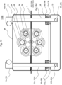
- FIGS. 1 to 8 A first embodiment of the multistage rolling mill of the present invention will be described with reference to FIGS. 1 to 8 .
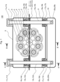
- FIG. 1 is a front view of a 20-high rolling mill according to the first embodiment
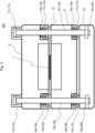
- FIG. 2 is a sectional view taken along arrows A-A' of FIG. 1
- FIG. 3 is a sectional view taken along arrows B-B' of FIG. 1
- FIG. 4 is a diagram depicting a state in which an upper mill housing is raised.
- the multistage rolling mill 100 of the present embodiment is a cluster-type 20-high rolling mill for rolling a strip 1, particularly, a rolling mill suitable for rolling a hard material such as a stainless steel strip, a magnetic steel strip, or a copper alloy.
- the multistage rolling mill 100 includes, as rolls, a pair of upper and lower work rolls 2, two pairs of upper and lower first intermediate rolls 3, three pairs of upper and lower second intermediate rolls 4, four pairs of upper partition backing bearing shafts A, B, C, and D and lower partition backing bearing shafts E, F, G, and H each including a partition backing bearing 5, a shaft 6, and a saddle 7.
- the pair of upper and lower work rolls 2 rolls the strip 1 which is a material to be rolled.
- the pair of upper and lower work rolls 2 are each in contact with and supported by the two pairs of upper and lower first intermediate rolls 3.
- the two pairs of upper and lower first intermediate rolls 3 are each in contact with and supported by the three pairs of upper and lower second intermediate rolls 4.
- first intermediate rolls 3 and the second intermediate rolls 4 constitute an intermediate roll group that supports the work rolls 2.
- the three pairs of upper and lower second intermediate rolls 4 are each in contact with and supported by the upper partition backing bearing shafts A, B, C, and D on the upper side in the vertical direction and the lower partition backing bearing shafts E, F, G, and H on the lower side in the vertical direction.
- Each of the partition backing bearing shafts A, B, C, D, E, F, G, and H includes the partition backing bearing 5, the shaft 6, and the saddle 7.
- the upper partition backing bearing shafts A, B, C, and D located on upper side in the vertical direction are supported by the upper mill housing 8 at the saddle 7.
- the lower backing bearing shafts E, F, G, and H located on lower side in the vertical direction are supported by the saddle 7 at the lower mill housing 9.
- a base mill housing 10 for fixing the multistage rolling mill 100 to a floor is provided.
- hydraulic cylinders 11a, 11b, 11c, and 11d that can raise and lower the upper mill housing 8 relative to the lower mill housing 9 are provided.
- the four columns 12a, 12b, 12c, and 12d have male screws 14a, 14b, 14c, and 14d and female screws 15a, 15b, 15c, and 15d disposed therein, respectively, between the upper mill housing 8 and the lower mill housing 9 so as to surround the peripheries thereof.
- the male screws 14a, 14b, 14c, and 14d and the female screws 15a, 15b, 15c, and 15d constitute an upper mill housing spacer.
- a load cell 13 is disposed between the upper mill housing 8 and the lower mill housing 9.
- the four columns 12a, 12b, 12c, and 12d have male screws 16a, 16b, 16c, and 16d and female screws 17a, 17b, 17c, and 17d disposed therein, respectively, between the lower mill housing 9 and the base mill housing 10 so as to surround the peripheries thereof.
- the male screws 16a, 16b, 16c, and 16d and the female screws 17a, 17b, 17c, and 17d constitute a lower mill housing spacer.
- the upper mill housing 8, the upper mill housing spacer, the load cell 13, the lower mill housing 9, the lower mill housing spacer, and the base mill housing 10 are sandwiched by the four columns 12a, 12b, 12c, and 12d.
- the hydraulic cylinders 11a, 11b, 11c, and 11d sandwich the upper mill housing 8, the lower mill housing 9, the base mill housing 10, the upper mill housing spacer, and the lower mill housing spacer through the four columns 12a, 12b, 12c, and 12d, thereby applying a prestress to the upper mill housing 8 and the lower mill housing 9, and securing a high mill rigidity.
- a position sensor can detect the height of the male screws 14a, 14b, 14c, and 14d or the height of the male screws 14a, 14b, 14c, and 14d converted from the rotational speed of the female screws 15a, 15b, 15c, and 15d, or the height of the upper mill housing 8.
- a position sensor can detect the height of the male screws 16a, 16b, 16c, and 16d or the height of the male screws 16a, 16b, 16c, and 16d converted from the rotational speed of the female screws 17a, 17b, 17c, and 17d, or the height of the lower mill housing 9.
- a lower mill housing lift-up hydraulic cylinder that holds the weight of the lower mill housing 9 can be provided.
- the upper mill housing spacer and the lower mill housing spacer can also provide an effect that leveling control on the operation side and on the driving side can be performed by changing the position in the height direction on the operation side and the position in the height direction on the driving side (the male screw 16a, the female screw 17a and the male screw 16b, the female screw 17b, or the male screw 16c, the female screw 17c and the male screw 16d, the female screw 17d).
- the upper mill housing spacer and the lower mill housing spacer are not limited to a screw structure with a driving actuator depicted in FIGS. 1 to 4 , and the worm jack can be adopted.
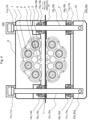
- FIG. 5 is a front view depicting another form of a spacer section
- FIG. 6 is a sectional view taken along arrows C-C' of FIG. 5 .
- the part of the column 12c is exemplified as a representative, and a similar structure can be adopted also at portions corresponding to the columns 12a, 12b, and 12d.
- the upper mill housing spacer and the lower mill housing spacer provided at the four columns 12a, 12b, 12c, and 12d may all be the same in configuration, may all be different in configuration, or two or more of them may be the same in configuration, and the configurations thereof are not particularly limited.
- the tapered wedge structure has an upper tapered wedge 21c and a lower tapered wedge 22 stacked in the vertical direction, while sandwiching the column 12c therebetween.
- the upper tapered wedge 21c and the lower tapered wedge 22c are shifted in a horizontal direction by the hydraulic cylinder 24c, whereby the thickness is continuously varied.
- the position of the upper mill housing 8 in the height direction can continuously be adjusted, and, in the case of the lower mill housing spacer, the position of the lower mill housing 9 in the height direction can continuously be adjusted.
- height adjustment can be continuously achieved in a wide range.
- the stepped rocker plate structure has a rocker plate 19c and a stepped rocker plate 20c stacked in the vertical direction, while sandwiching the column 12c therebetween.
- the stepped rocker plate 20c is shifted in a horizontal direction by the hydraulic cylinder 23c, with its thickness varied stepwise, and, in the case of the upper mill housing spacer, the height of the upper mill housing 8 can be adjusted stepwise. In the case of the lower mill housing spacer, the position of the lower mill housing 9 in the height direction can be adjusted stepwise. With such variation in height of the upper and lower mill housings, height adjustment can be made stepwise in a wide range.
- the stepped rocker plate 20c is not required to be rectangular parallelepiped in shape as depicted in FIGS. 5 and 6 and can adopt a structure having a disk shape and provided with a step to be rotated around the column 12c. In this structure, an advantage of being more compact is provided.
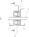
- FIG. 7 is a front view depicting a further form of the spacer section
- FIG. 8 is a sectional view taken along arrows D-D' of FIG. 7 .
- each hydraulic cylinder 26c is desirably controlled to a predetermined position by a servo valve or the like.
- any one portion of the lower mill housing spacers can adopt at least one of the screw structure with a driving actuator, the worm jack depicted in FIG. 1 or the like described above, the tapered wedge structure and the stepped rocker plate structure which are depicted in FIG. 5 or the like.
- a method of applying a rolling load in the multistage rolling mill 100 of the present embodiment there is, for example, a method in which eccentric rings of the partition backing bearing shafts B, C are lowered by an eccentric amount, to apply a rolling load.
- a rolling load can be measured as a differential load from application of a prestress load in the load cell 13.
- the cluster-type multistage rolling mill 100 of the first embodiment of the present invention described above includes the four columns 12a, 12b, 12c, and 12d that link, in an up-down direction, the four corners of each of the upper mill housing 8, the lower mill housing 9, and the base mill housing 10, a press-down section that is provided on the upper side of the four columns 12a, 12b, 12c, and 12d in the vertical direction and that can raise and lower the upper mill housing 8, and the lower mill housing spacer that is provided between the lower mill housing 9 and the base mill housing 10 and that adjusts the position of the lower mill housing 9 in the vertical direction.
- the lower mill housing 9 has such a structure as to be linked by the four columns 12a, 12b, 12c, and 12d and slidingly be guided relative to the base mill housing 10 fixed to the floor, so that a rigid and large outer housing and outer frame necessary in the conventional structure as a sliding guide for raising and lowering the lower mill housing 9 are unnecessary, and a very compact structure as a rolling mill can be realized.
- the height position of the lower mill housing 9 relative to the base mill housing 10 fixed to the floor is variable, so that a diameter of each roll, particularly, the use range of the work rolls 2 can be enlarged, and a pass line can be kept constant even when the diameter of the roll is varied.
- the male screws 16a, 16b, 16c, and 16d are lowered.
- the height of the lower mill housing 9 is lowered relative to the base mill housing 10 fixed to the floor, so that a space below the pass line is opened, and the small-diameter work rolls can be easily changed by the large-diameter work rolls.
- Such a multistage rolling mill 100 can roll with a high strip thickness accuracy and the like when rolling a hard material such as a stainless steel strip, a magnetic steel strip, or a copper alloy strip, and therefore, a highly rigid and compact multistage rolling mill of a cluster roll disposition using small-diameter work rolls suitable for obtaining a strip of high product quality is realized.
- the height position of the upper mill housing 8 is variable.
- the male screws 14a, 14b, 14c, and 14d are raised or lowered.
- the height of the upper mill housing 8 is raised, so that a space above the pass line is opened, and the upper work rolls can be changed from small-diameter work rolls to large-diameter work rolls on the upper side.
- the positions of the upper mill housing spacer and the lower mill housing spacer in the height direction there is obtained an effect that the pass line can be more easily kept constant.
- the press-down section sandwiches the upper mill housing 8, the lower mill housing 9, the base mill housing 10, the upper mill housing spacer, and the lower mill housing spacer through the four columns 12a, 12b, 12c, and 12d, thereby to apply a prestress, whereby a high mill rigidity can be secured.
- the lower mill housing spacer and the upper mill housing spacer each include at least any one of the screw structure with a driving actuator, the worm jack, the tapered wedge structure, the stepped rocker plate structure, and the hydraulic cylinder, whereby the positions of the lower mill housing 9 and the upper mill housing 8 in the height direction can be adjusted with high accuracy even with a simple configuration.
- the lower mill housing spacer and the upper mil housing spacer are disposed so as to surround each column 12a, 12b, 12c, and 12d of the four columns 12a, 12b, 12c, and 12d.
- a distance between a region where a prestress load is applied and the lower mill housing spacer or the upper mill housing spacer is large, particularly there is a fear that the base mill housing 10 may be deformed due to a stress in the height direction, but, according to the configuration described above, the positions of the lower mill housing 9 and the upper mill housing 8 in the height direction can be adjusted in a peripheral region of the four columns 12a, 12b, 12c, and 12d on which the prestress load is applied. For this reason, the base mill housing 10 or the like can be prevented from being deformed in such a direction in which the base mill housing 10 is deflected.
- the press-down sections are the hydraulic cylinders 11a, 11b, 11c, and 11d
- the upper mill housing 8 can be raised to a great extent as depicted in FIG. 4 .
- the gap between the work rolls 2 is enlarged, so that change of the work rolls 2 and passing of the strip 1 becomes easier.
- treatment of broken pieces upon breakage of the strip becomes easier, so that an effect that operability is more improved is obtained.
- the structure of the present embodiment can be applied also to a 12-high cluster-type multistage rolling mill in which the number of rolls is smaller, such as that of a third embodiment to be described later.
- FIG. 9 is a front view of a 20-high rolling mill according to the second embodiment.
- the same configurations as those of the first embodiment are denoted by the same reference characters, and descriptions thereof are basically omitted. The same applies also to the following embodiments.
- the multistage rolling mill 100A of the present embodiment depicted in FIG. 9 is a 20-high rolling mill similar to the multistage rolling mill 100 depicted in the first embodiment.
- the multistage rolling mill 100A of the present embodiment has a configuration in which the upper mill housing spacer including the male screws 14a, 14b, 14c, and 14d and the female screws 15a, 15b, 15c, and 15d and the load cell 13 are omitted from the multistage rolling mill 100 of the first embodiment.
- the hydraulic cylinders 11a, 11b, 11c, and 11d are used not for applying a prestress on the upper mill housing 8 and the lower mill housing 9 through the four columns 12a, 12b, 12c, and 12d, but for applying a rolling load.
- the lower mill housing spacer including the male screws 16a, 16b, 16c, and 16d and the female screws 17a, 17b, 17c, and 17d is configured such that rotation of the female screws 17a, 17b, 17c, and 17d by rotational driving of the worm gear and the hydraulic motor or the like raises or lowers the male screws 16a, 16b, 16c, and 16d.
- the multistage rolling mill 100A of the present embodiment cannot apply a prestress to the upper mill housing 8 and the lower mill housing 9 by the hydraulic cylinders 11a, 11b, 11c, and 11d, and therefore, it is more difficult than the first embodiment to enhance mill rigidity; however, since the number of constituent elements is smaller than that of the multistage rolling mill 100 of the first embodiment, there is an advantage of being more inexpensive.
- FIG. 10 is a front view of a 12-high rolling mill according to the third embodiment.
- the multistage rolling mill 100B of the present embodiment depicted in FIG. 10 is a cluster-type 12-high rolling mill for rolling a strip 1.
- the multistage rolling mill 100B includes a pair of upper and lower work rolls 2A, two pairs of upper and lower first intermediate rolls 3A, and three pairs of upper partition backing bearing shafts I, J, and K and lower partition backing bearing shafts L, M, and N each including a partition backing bearing 5A, a shaft 6A, and a saddle 7A.
- the pair of upper and lower work rolls 2A are each in contact with and supported by the two pairs of upper and lower first intermediate rolls 3A.
- the first intermediate rolls 3A constitute an intermediate roll group that supports the work rolls 2A.
- the two pairs of upper and lower first intermediate rolls 3A are each in contact with and supported by the upper partition backing bearing shafts I, J, and K and the lower partition backing bearing shafts L, M, and N.
- the upper partition backing bearing shafts I, J, and K on the upper side in the vertical direction are supported by the upper mill housing 8A through the their respective saddles 7A.
- the lower partition backing bearing shafts L, M, and N on the lower side in the vertical direction are supported by the lower mill housing 9A through their respective saddles 7A.
- a base mill housing 10 fixed to the floor is disposed on the lower side of the lower mill housing 9A in the vertical direction.
- worm jacks 18a, 18b, 18c, and 18d that can raise and lower the upper mill housing 8A relative to the lower mill housing 9A are provided.
- the worm jacks 18a, 18b, 18c, and 18d are connected respectively with four columns 12a1, 12b1, 12c1, and 12d1. These four columns 12a1, 12b1, 12c1, and 12d1 link, in an up-down direction, the four corners of each of the upper mill housing 8A, the lower mill housing 9A, and the base mill housing 10.
- the four columns 12a1, 12b1, 12c1, and 12d1 have the male screws 16a, 16b, 16c, and 16d and the female screws 17a, 17b, 17c, and 17d disposed, respectively, between the lower mill housing 9A and the base mill housing 10 so as to surround the peripheries thereof. Also in the present embodiment, the male screws 16a, 16b, 16c, and 16d and the female screws 17a, 17b, 17c, and 17d constitute the lower mill housing spacer.
- the worm jacks 18a, 18b, 18c, and 18d are used not for applying a prestress to the upper mill housing 8A and the lower mill housing 9A through the four columns 12a1, 12b1, 12c1, and 12d1, but for adjusting the height of the upper mill housing 8A.
- the upper mill housing 8A is raised in height thereof by the worm jacks 18a, 18b, 18c, and 18d, so that a space above the pass line is opened, and the upper work roll can be changed from the small-diameter work roll to the large-diameter work roll on the upper side.
- the male screws 16a, 16b, 16c, and 16d are lowered by rotating the female screws 17a, 17b, 17c, and 17d, resulting in that the height of the lower mill housing 9A is lowered relative to the base mill housing 10 fixed to the floor. Therefore, a space below the pass line is opened, and the lower work roll can be changed from the small-diameter work roll to the large-diameter work roll on the lower side. Besides, it also becomes possible to keep the pass line constant.
- a method for applying a rolling load in the multistage rolling mill 100B of the present embodiment there is a method in which, for example, a tapered wedge is inserted by the hydraulic cylinder (both omitted for convenience' sake of illustration), and the saddle 7A is lifted up, thereby to raise the lower partition backing bearing shaft M by the tapered wedge insertion amount.
- the structure of the present embodiment can be applied to the 20-high cluster-type multistage rolling mill of the first embodiment and the second embodiment described above.
Landscapes
- Engineering & Computer Science (AREA)
- Mechanical Engineering (AREA)
- Metal Rolling (AREA)
- Control Of Metal Rolling (AREA)
- Rolling Contact Bearings (AREA)
Claims (10)
- Laminoir à étages multiples (100, 100A, 100B) de type en groupe comprenant :une paire de cylindres de travail supérieur et inférieur (2, 2A) qui laminent une bande métallique (1) ;un groupe de cylindres intermédiaires (3, 3A, 4) qui supportent les cylindres de travail ;une pluralité d'arbres de palier de support de cloisonnage (A-N) incluant chacun un palier de support de cloisonnage (5, 5A), un arbre (6, 6A), et une selle (7, 7A) qui supporte le groupe de cylindres intermédiaires (3, 3A, 4) ;une cage de laminoir supérieure (8, 8A) qui supporte un arbre de palier de support de cloisonnage (A-D, I-K) de côté supérieur dans un sens vertical, parmi les arbres de palier de support de cloisonnage (A-N) ;une cage de laminoir inférieure (9, 9A) qui supporte un arbre de palier de support de cloisonnage (E-H, L-N) de côté inférieur dans un sens vertical, parmi les arbres de palier de support de cloisonnage (A-N) ;une cage de laminoir de base (10) disposée sur un côté inférieur de la cage de laminoir inférieure (9, 9A) dans le sens vertical ;et un espaceur (16a-d, 17a-d, 19c, 20c, 21c, 22c, 23c, 24c, 26c) de cage de laminoir inférieure qui est prévu entre la cage de laminoir inférieure (9, 9A) et la cage de laminoir de base (10) et qui ajuste une position de la cage de laminoir inférieure (9, 9A) dans le sens vertical ;caractérisé parquatre colonnes (12a, 12a1, 12b, 12b1, 12c, 12c1, 12d, 12d1) qui relient, dans un sens haut-bas, quatre angles de chacune de la cage de laminoir supérieure (8, 8A), de la cage de laminoir inférieure (9, 9A), et de la cage de laminoir de base (10) ;une section (11a-d, 18a-d) de pression vers le bas qui est prévue sur un côté supérieur des quatre colonnes (12a, 12a1, 12b, 12b1, 12c, 12c1, 12d, 12d1) dans le sens vertical et qui est apte à lever et abaisser la cage de laminoir supérieure (8, 8A).
- Laminoir à étages multiples (100, 100A, 100B) selon la revendication 1, comprenant en outre :
un espaceur (14a-d, 15a-d, 19c, 20c, 21c, 22c, 23c, 24c) de cage de laminoir supérieure qui est prévu entre la cage de laminoir supérieure (8, 8A) et la cage de laminoir inférieure (9, 9A) et qui ajuste une position de la cage de laminoir supérieure (8, 8A) dans le sens vertical. - Laminoir à étages multiples (100, 100A, 100B) selon la revendication 2,
dans lequel la section (11a-d, 18a-d) de pression vers le bas prend en sandwich la cage de laminoir supérieure (8, 8A), la cage de laminoir inférieure (9, 9A), la cage de laminoir de base (10), l'espaceur (14a-d, 15a-d, 19c, 20c, 21c, 22c, 23c, 24c) de cage de laminoir supérieure, et l'espaceur (16a-d, 17a-d, 19c, 20c, 21c, 22c, 23c, 24c, 26c) de cage de laminoir inférieure par l'intermédiaire des quatre colonnes (12a, 12a1, 12b, 12b1, 12c, 12c1, 12d, 12d1) pour appliquer une précontrainte. - Laminoir à étages multiples (100, 100A, 100B) selon la revendication 1,
dans lequel l'espaceur (16a-d, 17a-d, 19c, 20c, 21c, 22c, 23c, 24c, 26c) de cage de laminoir inférieure inclut au moins un(e) quelconque parmi une structure de vis avec un actionneur d'entraînement, un vérin à vis sans fin, une structure en coin conique, une structure de plaque de bascule étagée, et un cylindre hydraulique. - Laminoir à étages multiples (100, 100A, 100B) selon la revendication 2,
dans lequel l'espaceur (14a-d, 15a-d, 19c, 20c, 21c, 22c, 23c, 24c) de cage de laminoir supérieure inclut au moins un(e) quelconque parmi une structure de vis avec un actionneur d'entraînement, un vérin à vis sans fin, une structure en coin conique, et une structure de plaque de bascule étagée. - Laminoir à étages multiples (100, 100A, 100B) selon la revendication 3,
dans lequel l'espaceur (16a-d, 17a-d, 19c, 20c, 21c, 22c, 23c, 24c, 26c) de cage de laminoir inférieure est disposé de façon à entourer chacune des quatre colonnes (12a, 12a1, 12b, 12b1, 12c, 12c1, 12d, 12d1). - Laminoir à étages multiples (100, 100A, 100B) selon la revendication 3,
dans lequel l'espaceur (14a-d, 15a-d, 19c, 20c, 21c, 22c, 23c, 24c) de cage de laminoir supérieure est disposé de façon à entourer chacune des quatre colonnes (12a, 12a1, 12b, 12b1, 12c, 12c1, 12d, 12d1). - Laminoir à étages multiples (100, 100A, 100B) selon la revendication 1,dans lequel le groupe de cylindres intermédiaires (3, 4) inclut deux paires de premiers cylindres intermédiaires (3) supérieurs et inférieurs qui supportent les cylindres de travail (2), et trois paires de deuxièmes cylindres intermédiaires (4) supérieurs et inférieurs qui supportent les premiers cylindres intermédiaires (3), etles arbres de palier de support de cloisonnage (A-H) supportent les deuxièmes cylindres intermédiaires (4) par quatre paires d'arbres de palier de support de cloisonnage supérieurs et inférieurs (A-H).
- Laminoir à étages multiples (100, 100A, 100B) selon la revendication 1,dans lequel le groupe de cylindres intermédiaires (3A) inclut deux paires de premiers cylindres intermédiaires supérieurs et inférieurs qui supportent les cylindres de travail (2A), etles arbres de palier de support de cloisonnage (I-N) supportent les premiers cylindres intermédiaires par trois paires d'arbres de palier de support de cloisonnage supérieurs et inférieurs (I-N).
- Laminoir à étages multiples (100, 100A, 100B) selon la revendication 1,
dans lequel la section (11a-d, 18a-d) de pression vers le bas est un cylindre hydraulique ou un vérin à vis sans fin.
Applications Claiming Priority (2)
| Application Number | Priority Date | Filing Date | Title |
|---|---|---|---|
| JP2020008018 | 2020-01-22 | ||
| PCT/JP2021/001937 WO2021149747A1 (fr) | 2020-01-22 | 2021-01-21 | Laminoir à étages multiples |
Publications (3)
| Publication Number | Publication Date |
|---|---|
| EP4094855A1 EP4094855A1 (fr) | 2022-11-30 |
| EP4094855A4 EP4094855A4 (fr) | 2024-02-28 |
| EP4094855B1 true EP4094855B1 (fr) | 2025-06-04 |
Family
ID=76992455
Family Applications (1)
| Application Number | Title | Priority Date | Filing Date |
|---|---|---|---|
| EP21744250.8A Active EP4094855B1 (fr) | 2020-01-22 | 2021-01-21 | Laminoir à étages multiples |
Country Status (5)
| Country | Link |
|---|---|
| US (1) | US12030098B2 (fr) |
| EP (1) | EP4094855B1 (fr) |
| JP (1) | JP7167368B2 (fr) |
| CN (1) | CN114728316B (fr) |
| WO (1) | WO2021149747A1 (fr) |
Families Citing this family (2)
| Publication number | Priority date | Publication date | Assignee | Title |
|---|---|---|---|---|
| CN114713642B (zh) * | 2022-06-08 | 2022-09-09 | 太原理工大学 | 一种液压方式调控的新型背衬辊 |
| FR3145882B1 (fr) * | 2023-02-22 | 2025-03-21 | Fives Dms | Laminoir à cage mobile et à porte étanche |
Family Cites Families (16)
| Publication number | Priority date | Publication date | Assignee | Title |
|---|---|---|---|---|
| US3076360A (en) * | 1958-08-22 | 1963-02-05 | Sendzimir Tadeusz | Clam shell cold rolling mill |
| JPS498442A (fr) * | 1972-05-23 | 1974-01-25 | ||
| JPH0523719A (ja) * | 1991-07-18 | 1993-02-02 | Kobe Steel Ltd | 多段クラスタ圧延機 |
| US5596899A (en) | 1994-07-22 | 1997-01-28 | T. Sendzimir, Inc. | Mill housings for cluster mills |
| KR100207067B1 (ko) * | 1996-05-18 | 1999-07-01 | 지원국 | 전기 가열식 금속 스트립 압연기 |
| US5857372A (en) | 1997-02-06 | 1999-01-12 | T. Sendzimir, Inc. | Housing for cluster mills |
| JP3603033B2 (ja) * | 2001-02-20 | 2004-12-15 | 株式会社日立製作所 | クラスター式多段圧延機 |
| US7234334B1 (en) * | 2002-08-02 | 2007-06-26 | United Grinding And Machine Company | Saddle for backing assemblies in a rolling mill |
| CN201008878Y (zh) * | 2007-02-14 | 2008-01-23 | 中冶京诚工程技术有限公司 | 多辊轧机 |
| US7765844B2 (en) * | 2007-12-20 | 2010-08-03 | Intergrated Industrial Systems, Inc. | Prestressed rolling mill housing assembly with improved operational features |
| US9003854B2 (en) * | 2011-06-16 | 2015-04-14 | I2S, Llc | Split housing cluster mill designed for temper and cold rolling |
| JP2013018034A (ja) | 2011-07-12 | 2013-01-31 | Kobe Steel Ltd | 圧延機のロール組替方法 |
| JP5894849B2 (ja) | 2012-04-25 | 2016-03-30 | Primetals Technologies Japan株式会社 | 作業ロールシフト機能を具備した多段圧延機 |
| JP5905322B2 (ja) * | 2012-04-25 | 2016-04-20 | Primetals Technologies Japan株式会社 | 作業ロールシフト機能を具備した圧延機 |
| CN106424132B (zh) * | 2016-10-27 | 2019-04-05 | 天津市中重科技工程有限公司 | 一种用于h型钢生产的预应力万能轧机 |
| CN113646100B (zh) | 2019-04-04 | 2023-06-27 | 日本森吉米尔公司 | 多辊轧机及多辊轧机中的分割式支承轴承组装轴的更换方法 |
-
2021
- 2021-01-21 EP EP21744250.8A patent/EP4094855B1/fr active Active
- 2021-01-21 JP JP2021572778A patent/JP7167368B2/ja active Active
- 2021-01-21 CN CN202180006452.9A patent/CN114728316B/zh active Active
- 2021-01-21 US US17/774,209 patent/US12030098B2/en active Active
- 2021-01-21 WO PCT/JP2021/001937 patent/WO2021149747A1/fr not_active Ceased
Also Published As
| Publication number | Publication date |
|---|---|
| WO2021149747A1 (fr) | 2021-07-29 |
| EP4094855A1 (fr) | 2022-11-30 |
| JPWO2021149747A1 (fr) | 2021-07-29 |
| EP4094855A4 (fr) | 2024-02-28 |
| JP7167368B2 (ja) | 2022-11-08 |
| CN114728316A (zh) | 2022-07-08 |
| CN114728316B (zh) | 2024-07-02 |
| US20220379358A1 (en) | 2022-12-01 |
| US12030098B2 (en) | 2024-07-09 |
Similar Documents
| Publication | Publication Date | Title |
|---|---|---|
| US12030098B2 (en) | Multistage rolling mill | |
| JP5894849B2 (ja) | 作業ロールシフト機能を具備した多段圧延機 | |
| US7475581B2 (en) | Method of increasing the control precision of the path of a product in a levelling machine with interlocking rollers, and levelling installation used to implement same | |
| US4934166A (en) | Rolling mill with axially shiftable rolls and process for adjusting the profile of such rolls | |
| JP3282939B2 (ja) | クラスタ・ミルのハウジング組立体 | |
| KR100407756B1 (ko) | 하우징 없는 롤 받침대 | |
| JPH0688055B2 (ja) | 圧延機、及び圧延設備 | |
| JP2011508672A (ja) | 改善した動作特性を備えるプレストレスを与えた圧延機ハウジングのアセンブリ | |
| US9003854B2 (en) | Split housing cluster mill designed for temper and cold rolling | |
| EP1425118B1 (fr) | Cage universelle avec regulation de l'intervalle entre les cylindres | |
| JP3097530B2 (ja) | クラスタ式多段圧延機及び圧延方法 | |
| JP2002001406A (ja) | モジュール構造の圧延機、特に傾斜圧延機またはディッシャ圧延機 | |
| EP1107835B1 (fr) | Cage de laminoir dotee de cylindres d'appui et/ou de travail croises | |
| DE3642128A1 (de) | Unterstuetzungssystem fuer teleskopspiegel | |
| US6151944A (en) | Rolling installation for flat products | |
| EP0998992B1 (fr) | Dispositif de réglage de la position des cylindres dans des laminoirs à cylindres multiples | |
| JP4336042B2 (ja) | クロスロールを有するロールスタンドのための軸受 | |
| Dutton | An investigation into the design and performance of an automatic shape control system for a Sendzimir cold rolling mill | |
| JPH04361802A (ja) | クロスミル | |
| US12434283B2 (en) | Hot rolling mills and hot rolling methods | |
| JPH0222082Y2 (fr) | ||
| JPH11188407A (ja) | ハウジングレスユニバ−サル圧延機 | |
| JPS6222686B2 (fr) | ||
| Guo | Recent Advances on 20-Hi Cluster Mill Optimization | |
| JPH0366055B2 (fr) |
Legal Events
| Date | Code | Title | Description |
|---|---|---|---|
| STAA | Information on the status of an ep patent application or granted ep patent |
Free format text: STATUS: THE INTERNATIONAL PUBLICATION HAS BEEN MADE |
|
| PUAI | Public reference made under article 153(3) epc to a published international application that has entered the european phase |
Free format text: ORIGINAL CODE: 0009012 |
|
| STAA | Information on the status of an ep patent application or granted ep patent |
Free format text: STATUS: REQUEST FOR EXAMINATION WAS MADE |
|
| 17P | Request for examination filed |
Effective date: 20220328 |
|
| AK | Designated contracting states |
Kind code of ref document: A1 Designated state(s): AL AT BE BG CH CY CZ DE DK EE ES FI FR GB GR HR HU IE IS IT LI LT LU LV MC MK MT NL NO PL PT RO RS SE SI SK SM TR |
|
| DAV | Request for validation of the european patent (deleted) | ||
| DAX | Request for extension of the european patent (deleted) | ||
| A4 | Supplementary search report drawn up and despatched |
Effective date: 20240131 |
|
| RIC1 | Information provided on ipc code assigned before grant |
Ipc: B21B 31/20 20060101ALI20240125BHEP Ipc: B21B 31/02 20060101ALI20240125BHEP Ipc: B21B 13/14 20060101AFI20240125BHEP |
|
| STAA | Information on the status of an ep patent application or granted ep patent |
Free format text: STATUS: EXAMINATION IS IN PROGRESS |
|
| GRAP | Despatch of communication of intention to grant a patent |
Free format text: ORIGINAL CODE: EPIDOSNIGR1 |
|
| STAA | Information on the status of an ep patent application or granted ep patent |
Free format text: STATUS: GRANT OF PATENT IS INTENDED |
|
| INTG | Intention to grant announced |
Effective date: 20250228 |
|
| GRAS | Grant fee paid |
Free format text: ORIGINAL CODE: EPIDOSNIGR3 |
|
| GRAA | (expected) grant |
Free format text: ORIGINAL CODE: 0009210 |
|
| STAA | Information on the status of an ep patent application or granted ep patent |
Free format text: STATUS: THE PATENT HAS BEEN GRANTED |
|
| AK | Designated contracting states |
Kind code of ref document: B1 Designated state(s): AL AT BE BG CH CY CZ DE DK EE ES FI FR GB GR HR HU IE IS IT LI LT LU LV MC MK MT NL NO PL PT RO RS SE SI SK SM TR |
|
| RAP3 | Party data changed (applicant data changed or rights of an application transferred) |
Owner name: SENDZIMIR JAPAN, LTD. |
|
| REG | Reference to a national code |
Ref country code: GB Ref legal event code: FG4D |
|
| REG | Reference to a national code |
Ref country code: CH Ref legal event code: EP |
|
| REG | Reference to a national code |
Ref country code: DE Ref legal event code: R096 Ref document number: 602021031803 Country of ref document: DE |
|
| REG | Reference to a national code |
Ref country code: IE Ref legal event code: FG4D |
|
| REG | Reference to a national code |
Ref country code: NL Ref legal event code: MP Effective date: 20250604 |
|
| PG25 | Lapsed in a contracting state [announced via postgrant information from national office to epo] |
Ref country code: FI Free format text: LAPSE BECAUSE OF FAILURE TO SUBMIT A TRANSLATION OF THE DESCRIPTION OR TO PAY THE FEE WITHIN THE PRESCRIBED TIME-LIMIT Effective date: 20250604 Ref country code: ES Free format text: LAPSE BECAUSE OF FAILURE TO SUBMIT A TRANSLATION OF THE DESCRIPTION OR TO PAY THE FEE WITHIN THE PRESCRIBED TIME-LIMIT Effective date: 20250604 |
|
| REG | Reference to a national code |
Ref country code: LT Ref legal event code: MG9D |
|
| PG25 | Lapsed in a contracting state [announced via postgrant information from national office to epo] |
Ref country code: NO Free format text: LAPSE BECAUSE OF FAILURE TO SUBMIT A TRANSLATION OF THE DESCRIPTION OR TO PAY THE FEE WITHIN THE PRESCRIBED TIME-LIMIT Effective date: 20250904 Ref country code: GR Free format text: LAPSE BECAUSE OF FAILURE TO SUBMIT A TRANSLATION OF THE DESCRIPTION OR TO PAY THE FEE WITHIN THE PRESCRIBED TIME-LIMIT Effective date: 20250905 |
|
| PG25 | Lapsed in a contracting state [announced via postgrant information from national office to epo] |
Ref country code: PL Free format text: LAPSE BECAUSE OF FAILURE TO SUBMIT A TRANSLATION OF THE DESCRIPTION OR TO PAY THE FEE WITHIN THE PRESCRIBED TIME-LIMIT Effective date: 20250604 |
|
| PG25 | Lapsed in a contracting state [announced via postgrant information from national office to epo] |
Ref country code: BG Free format text: LAPSE BECAUSE OF FAILURE TO SUBMIT A TRANSLATION OF THE DESCRIPTION OR TO PAY THE FEE WITHIN THE PRESCRIBED TIME-LIMIT Effective date: 20250604 |
|
| PG25 | Lapsed in a contracting state [announced via postgrant information from national office to epo] |
Ref country code: HR Free format text: LAPSE BECAUSE OF FAILURE TO SUBMIT A TRANSLATION OF THE DESCRIPTION OR TO PAY THE FEE WITHIN THE PRESCRIBED TIME-LIMIT Effective date: 20250604 |
|
| PG25 | Lapsed in a contracting state [announced via postgrant information from national office to epo] |
Ref country code: RS Free format text: LAPSE BECAUSE OF FAILURE TO SUBMIT A TRANSLATION OF THE DESCRIPTION OR TO PAY THE FEE WITHIN THE PRESCRIBED TIME-LIMIT Effective date: 20250904 |
|
| PG25 | Lapsed in a contracting state [announced via postgrant information from national office to epo] |
Ref country code: LV Free format text: LAPSE BECAUSE OF FAILURE TO SUBMIT A TRANSLATION OF THE DESCRIPTION OR TO PAY THE FEE WITHIN THE PRESCRIBED TIME-LIMIT Effective date: 20250604 |
|
| PG25 | Lapsed in a contracting state [announced via postgrant information from national office to epo] |
Ref country code: NL Free format text: LAPSE BECAUSE OF FAILURE TO SUBMIT A TRANSLATION OF THE DESCRIPTION OR TO PAY THE FEE WITHIN THE PRESCRIBED TIME-LIMIT Effective date: 20250604 |
|
| PG25 | Lapsed in a contracting state [announced via postgrant information from national office to epo] |
Ref country code: PT Free format text: LAPSE BECAUSE OF FAILURE TO SUBMIT A TRANSLATION OF THE DESCRIPTION OR TO PAY THE FEE WITHIN THE PRESCRIBED TIME-LIMIT Effective date: 20251006 |
|
| REG | Reference to a national code |
Ref country code: AT Ref legal event code: MK05 Ref document number: 1799892 Country of ref document: AT Kind code of ref document: T Effective date: 20250604 |
|
| PG25 | Lapsed in a contracting state [announced via postgrant information from national office to epo] |
Ref country code: IS Free format text: LAPSE BECAUSE OF FAILURE TO SUBMIT A TRANSLATION OF THE DESCRIPTION OR TO PAY THE FEE WITHIN THE PRESCRIBED TIME-LIMIT Effective date: 20251004 |
|
| PG25 | Lapsed in a contracting state [announced via postgrant information from national office to epo] |
Ref country code: AT Free format text: LAPSE BECAUSE OF FAILURE TO SUBMIT A TRANSLATION OF THE DESCRIPTION OR TO PAY THE FEE WITHIN THE PRESCRIBED TIME-LIMIT Effective date: 20250604 Ref country code: SM Free format text: LAPSE BECAUSE OF FAILURE TO SUBMIT A TRANSLATION OF THE DESCRIPTION OR TO PAY THE FEE WITHIN THE PRESCRIBED TIME-LIMIT Effective date: 20250604 |
|
| PG25 | Lapsed in a contracting state [announced via postgrant information from national office to epo] |
Ref country code: CZ Free format text: LAPSE BECAUSE OF FAILURE TO SUBMIT A TRANSLATION OF THE DESCRIPTION OR TO PAY THE FEE WITHIN THE PRESCRIBED TIME-LIMIT Effective date: 20250604 |
|
| PG25 | Lapsed in a contracting state [announced via postgrant information from national office to epo] |
Ref country code: EE Free format text: LAPSE BECAUSE OF FAILURE TO SUBMIT A TRANSLATION OF THE DESCRIPTION OR TO PAY THE FEE WITHIN THE PRESCRIBED TIME-LIMIT Effective date: 20250604 |
|
| PG25 | Lapsed in a contracting state [announced via postgrant information from national office to epo] |
Ref country code: SK Free format text: LAPSE BECAUSE OF FAILURE TO SUBMIT A TRANSLATION OF THE DESCRIPTION OR TO PAY THE FEE WITHIN THE PRESCRIBED TIME-LIMIT Effective date: 20250604 |
|
| REG | Reference to a national code |
Ref country code: DE Ref legal event code: R097 Ref document number: 602021031803 Country of ref document: DE |
|
| PLBE | No opposition filed within time limit |
Free format text: ORIGINAL CODE: 0009261 |
|
| STAA | Information on the status of an ep patent application or granted ep patent |
Free format text: STATUS: NO OPPOSITION FILED WITHIN TIME LIMIT |
|
| PG25 | Lapsed in a contracting state [announced via postgrant information from national office to epo] |
Ref country code: DK Free format text: LAPSE BECAUSE OF FAILURE TO SUBMIT A TRANSLATION OF THE DESCRIPTION OR TO PAY THE FEE WITHIN THE PRESCRIBED TIME-LIMIT Effective date: 20250604 |
|
| PGFP | Annual fee paid to national office [announced via postgrant information from national office to epo] |
Ref country code: DE Payment date: 20260126 Year of fee payment: 6 |
|
| PGFP | Annual fee paid to national office [announced via postgrant information from national office to epo] |
Ref country code: IT Payment date: 20260220 Year of fee payment: 6 |
|
| REG | Reference to a national code |
Ref country code: CH Ref legal event code: L10 Free format text: ST27 STATUS EVENT CODE: U-0-0-L10-L00 (AS PROVIDED BY THE NATIONAL OFFICE) Effective date: 20260416 |
|
| PGFP | Annual fee paid to national office [announced via postgrant information from national office to epo] |
Ref country code: FR Payment date: 20260223 Year of fee payment: 6 |
|
| 26N | No opposition filed |
Effective date: 20260305 |