EP4094888A1 - Verfahren zur bearbeitung mehrerer werkstückrohlinge mit einer werkzeugmaschine und ein satz von spezifischen trägern für das verfahren dafür - Google Patents
Verfahren zur bearbeitung mehrerer werkstückrohlinge mit einer werkzeugmaschine und ein satz von spezifischen trägern für das verfahren dafür Download PDFInfo
- Publication number
- EP4094888A1 EP4094888A1 EP21176447.7A EP21176447A EP4094888A1 EP 4094888 A1 EP4094888 A1 EP 4094888A1 EP 21176447 A EP21176447 A EP 21176447A EP 4094888 A1 EP4094888 A1 EP 4094888A1
- Authority
- EP
- European Patent Office
- Prior art keywords
- support
- customized
- mounting support
- mounting
- mating part
- Prior art date
- Legal status (The legal status is an assumption and is not a legal conclusion. Google has not performed a legal analysis and makes no representation as to the accuracy of the status listed.)
- Withdrawn
Links
Images




Classifications
-
- B—PERFORMING OPERATIONS; TRANSPORTING
- B24—GRINDING; POLISHING
- B24B—MACHINES, DEVICES, OR PROCESSES FOR GRINDING OR POLISHING; DRESSING OR CONDITIONING OF ABRADING SURFACES; FEEDING OF GRINDING, POLISHING, OR LAPPING AGENTS
- B24B5/00—Machines or devices designed for grinding surfaces of revolution on work, including those which also grind adjacent plane surfaces; Accessories therefor
- B24B5/18—Machines or devices designed for grinding surfaces of revolution on work, including those which also grind adjacent plane surfaces; Accessories therefor involving centreless means for supporting, guiding, floating or rotating work
- B24B5/22—Machines or devices designed for grinding surfaces of revolution on work, including those which also grind adjacent plane surfaces; Accessories therefor involving centreless means for supporting, guiding, floating or rotating work for grinding cylindrical surfaces, e.g. on bolts
-
- B—PERFORMING OPERATIONS; TRANSPORTING
- B24—GRINDING; POLISHING
- B24B—MACHINES, DEVICES, OR PROCESSES FOR GRINDING OR POLISHING; DRESSING OR CONDITIONING OF ABRADING SURFACES; FEEDING OF GRINDING, POLISHING, OR LAPPING AGENTS
- B24B41/00—Component parts such as frames, beds, carriages, headstocks
- B24B41/06—Work supports, e.g. adjustable steadies
- B24B41/066—Work supports, e.g. adjustable steadies adapted for supporting work in the form of tools, e.g. drills
-
- B—PERFORMING OPERATIONS; TRANSPORTING
- B24—GRINDING; POLISHING
- B24B—MACHINES, DEVICES, OR PROCESSES FOR GRINDING OR POLISHING; DRESSING OR CONDITIONING OF ABRADING SURFACES; FEEDING OF GRINDING, POLISHING, OR LAPPING AGENTS
- B24B41/00—Component parts such as frames, beds, carriages, headstocks
- B24B41/06—Work supports, e.g. adjustable steadies
- B24B41/067—Work supports, e.g. adjustable steadies radially supporting workpieces
-
- B—PERFORMING OPERATIONS; TRANSPORTING
- B24—GRINDING; POLISHING
- B24B—MACHINES, DEVICES, OR PROCESSES FOR GRINDING OR POLISHING; DRESSING OR CONDITIONING OF ABRADING SURFACES; FEEDING OF GRINDING, POLISHING, OR LAPPING AGENTS
- B24B5/00—Machines or devices designed for grinding surfaces of revolution on work, including those which also grind adjacent plane surfaces; Accessories therefor
- B24B5/18—Machines or devices designed for grinding surfaces of revolution on work, including those which also grind adjacent plane surfaces; Accessories therefor involving centreless means for supporting, guiding, floating or rotating work
- B24B5/307—Means for supporting work
Definitions
- the present invention relates to a method of machining several workpiece blanks, in particular cutting tools, of different diameters.
- the invention also relates to a set of customized supports for supporting workpiece blanks of different diameters as well as an automated system to carry out the aforesaid method.
- grinding wheels exert significant forces during material removal. These forces cause the tool blank to be deformed/displaced by bending/twisting, for example, resulting in dimensional errors or vibrations that can impair the quality of the cutting edges.
- Another method that can limit dimensional errors or vibrations during tool machining is to support the blanks at specific positions and at specific times during the grinding cycle with one or more supports to prevent the tools from bending or vibrating under the effect of the grinding forces.
- An aim of the present invention is therefore to provide a set of customized supports for supporting a distal portion of different workpieces during machining of the workpiece and adapted for automated switching of customized support as a function of the workpiece to be machined.
- Another aim of the present invention is to provide a method for changing the customized support as as a function of the workpiece to be machined.
- Each customized support is adapted to be hold by a same mounting support aligned with a spindle of a machine tool or to respective mounting support to be aligned with the spindle.
- Each customized support has a supporting surface for supporting a portion of a workpiece blank during machining. The shape and/or the dimensions of the supporting surface is different between each customized support of the set of customized supports so as to offset the difference in diameter between different workpiece blanks having different diameter such that a portion of a workpiece blank to be machined is always supported by a customized support when mounted on the same mounting support of the machine tool or by a customized support of respective mounting support without requiring any height adjustment of the mounting support.
- each customized support comprises a concave surface for supporting a distal portion of a workpiece blank during machining.
- the radius of curvature of the concave surface of each customized support of the set of customized supports is different in order to offset said difference in diameter between different workpiece blanks having different diameter.
- each customized support comprises a gripping interface for automated interchangeability in the mounting support of a customized support with another customized support as a function of the diameter of the workpiece blank to be machined.
- each customized support comprises a mating part configured to be held in a complementary mating part of the mounting support.
- the mating part of each customized support is a convex bottom surface and the complementary mating part of the mounting support is a concave surface having a radius of curvature corresponding substantially to the radius of curvature of said convex bottom surface of each customized support.
- Another aspect of the invention relates to a method of machining several workpiece blanks with a machine tool, notably a grinding machine.
- the method comprises the seps of:
- step b. may be performed before step a. and step e. may be performed before step d.
- a robotic arm with an end-effector is placed within arm reach of the mounting support and of a support storage storing different customized supports according to any of paragraphs [0010] - [0013], the step of interchanging said customized support with another customized support comprising:
- the mounting support comprises an elastic portion and actuating means arranged to cooperate with the elastic portion.
- the elastic portion comprises a distal end which forms a portion of the complementary mating part.
- the automated system comprises a machine tool, notably a grinding machine having a spindle, an automated clamping support, a support storage for storing different customized supports of the set of customized supports according to any one of paragraphs [0010] - [0013], and a robotic arm comprising an end effector configured to grip a customized support.
- the robotic arm is configured to be actuated to bring a mating part of any customized support from the support storage into a complementary mating part of the mounting support and vice versa.
- the automated clamping support is configured to bring the complementary mating part from a clamping configuration to an unclamped configuration so that the robotic arm may remove the customized support from the mounting support and from an unclamped configuration to a clamping configuration once the robotic arm has placed another customized support in the mounting support.
- the support storage is a compartmentalized storage comprising at least six compartments, preferably at least ten compartments. Each compartment is adapted to store a customized support according to any one of paragraphs [0010] - [0013].
- the shape and/or dimensions of the supporting surface of each customized support sored or to be stored in one compartment is different from the shape and/or dimensions of the supporting surface of the customized support stored or to be stored in any other compartment of the compartmentalized storage.
- the automated clamping support comprises an actuator.
- the actuator comprises a piston, a lever actuable by the piston, and actuating means arranged to cooperate with an elastic portion having a distal end which forms a portion of the complementary mating part in order to bend outwardly the elastic portion to bring the mounting support from a clamping configuration to an unclamped configuration.
- the mounting support comprises a longitudinal passage extending from a first lateral side of the mounting support through the mounting support up to a longitudinal slit extending upwardly up to the complementary mating part.
- a rod is arranged inside the longitudinal passage and comprises a first end in abutment against the elastic portion of the mounting support and a second end protruding from the first lateral side of the mounting support.
- the lever comprises an actuating part and is configured to pivot about an axis of rotation when actuated by the piston to bring and push the actuating part against the second end of the rod to impart a translation movement to the rod causing the first end of the rod, in abutment against the elastic portion of the mounting support, to push against the elastic portion thereby bending outwardly to widen the complementary mating part of the mounting support to bring it into an un-clamped configuration.
- the lever is arranged to cooperate with an elastic member configured to urge the lever in a non-actuating configuration.
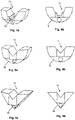
- each customized support of the set of customized supports 10a, 10b, 10c comprises a supporting surface in the form of a concave surface 12a, 12b, 12c arranged on an upper portion of the customized support and a mating part 16 arranged on a lower portion of the customized support.
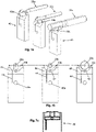
- the mating part 16 of each customized support 10a, 10b, 10c of the set of customized supports are identical and are shaped to be locked into a complementary mating part 42 of a mounting support 40 as shown for example in Figure 7b .
- the mating part 16 may have for example circular convex surface while the complementary mating part 42 may a corresponding circular concave surface.
- the mating part may however have other shapes, such as a rectangular shape to be mounted on a mounting support 40 comprising a complementary rectangular shaped recess as shown in Figure 7c .
- the respective concave surface 12a, 12b, 12c of respective customized supports 10a, 10b, 10c, which form together the set of customized supports, is however unique in the sense that their respective radius of curvatures R 1 , R 2 , R 3 differs from one another.
- This unique concave surface 12a, 12b, 12c is designed to offset the difference in diameter between different workpiece blanks 20a, 20b, 20c to support a distal portion of a workpiece blank 20a, 20b, 20c with a specific diameter when the workpiece blank is mounted in the spindle 112 of a machine tool, notably a grinding machine 110 as shown for example in Figure 8 .
- a portion of a workpiece blank 20a, 20b, 20c to be machined is therefore always supported by a customized support 10a, 10b 10c designed specifically for the specific diameter of that portion when the corresponding customized support is mounted on the same mounting support 40 of the machine tool without requiring any height adjustment of the mounting support between the machining of two workpiece blanks of different diameters, which significantly reduce machine downtime.
- the number of customized supports 10a, 10b, 10c, with a unique concave surface 12a, 12b, 12c, forming the set of customized supports may vary according to the application but the greater the number is, the more diverse the machined workpieces are without requiring human intervention for the height adjustment of the mounting support 40.
- the set of customized supports 10a, 10b, 10c may comprise at least ten customized supports with a unique concave surface, for example 15 unique customized supports or even more.
- each customized support 10a, 10b, 10c comprises a gripping interface 14 for automated interchangeability in the mounting support 40 of a customized support 10a with another customized support 10b, 10c as a function of the diameter of the workpiece blank 20a, 20b, 20c to be machined.
- the gripping interface 14 may take different forms for example a hole or a protruding part.
- each customized support adapted to support a distal end of the workpiece blank does not necessarily have a continuous concave surface as shown in Figures 1a to 3b .
- the supporting surface 11 may have a non-continuous concave surface having two rounded portions and a notch 13 therebetween as shown in Figures 4a and 4b .
- the supporting surface 11 is in the form of a V-shaped surface as shown in Figure 5a to 6b .
- the mating part may also have a shape different than a circular convex surface, for example a triangle prism to be fitted inside a corresponding V-shaped mating part as shown in Figures 6a and 6b .
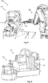
- an automated system 100 for automated interchangeability of customized supports in the mounting support 40 is illustrated for example in Figure 8 .
- the automated system 100 comprises the machine tool 110 for example a grinding machine, a support storage 130 having a plurality of compartment 132 ( Figure 9 ) for sorting in each compartment a customized support 10a, 10b, 10c with a unique concave surface 12a, 12b, 12c, an automated clamping support 30 and a robotic arm 120 placed within arm reach of the automated clamping support 30 and of the support storage 130.
- the automated clamping support 30 comprises the mounting support 40 and an actuator 60 configured to actuate the mounting support 40 to bring it from a clamping configuration to an unclamped configuration and vice versa as described in detail subsequently.
- a customized support 10a is firmly held by the mounting support 40 in the clamping configuration while the customized support can be removed from the mounting support 40 in the unclamped configuration.
- the support storage 130 is preferably compartmentalized storage comprising different compartments 132. Each compartment 132 stores or is adapted to store a customized support with a unique concave surface.
- the robotic arm 120 comprises an end-effector 122 for gripping the gripping interface 14 of any customized support lodged in their respective compartment 132 to bring the mating part 16 of a particular customized support, chosen as a function of the diameter of the workpiece blank 20a, 20b, 20c to be machined, inside the complementary mating part 42 of the mounting support 40, whereupon the mounting support is actuated to bring it in a clamping configuration.
- the mounting support 40 is configured to cooperate with the actuator 60.
- the mounting support 40 comprises an elastic portion 46 having a distal end which forms a portion of the complementary mating part 42 of the mounting support.
- the elastic portion 46 is separated from the main part of the mounting support 40 by a longitudinal slit 44 extending upwardly to the complementary mating part 42.
- the actuator 60 comprises a connecting part 68 fixed to the elastic portion 46 and an actuable assembly configured to actuate the connecting part 68 in a radial direction to bend the elastic portion 46 outwardly so as to widen the complementary mating part 42 of the mounting support 40 such that the end-effector 122 of the robotic arm 120 may position the mating part 16 of any customized support 10a, 10b, 10c in the complementary mating part 42 of the mounting support.
- the actuable assembly comprises a piston 62, a rigid linking part 64 and a lever 66.
- the lever 66 comprises a first end pivotally connected to the rigid linking part 64, a second end pivotally mounted around a pivot 70 fixed to the connecting part 68, and a cylindrical hole 67 mounted around a pivot 48 which is for example a pin which forms an integral part with the mounting support 40 or which is partly fitted inside a corresponding hole 48a of the mounted support 40 as illustrated in Figures 7a and 7b .
- the piston 62 Upon actuation of the actuator 60, the piston 62 is actuated to produce a stroke, for example along an upward direction, which causes the rigid linking part 64 to move upwards, thereby pivoting the lever 66 in a counterclockwise direction around the pivot 48 of the mounting support 40 in order to exert on the connecting part 68 a radial force to bend the elastic portion 46 outwardly to bring the mounting support 40 from a clamping configuration to an unclamped configuration.
- the end-effector 122 of the robotic arm 120 can position the mating part 16 of any customized support 10a, 10b, 10c inside the complementary mating part 42 of the mounting support 40 as a function of the diameter of the workpiece blank 20a, 20b, 20c to be machined.
- the piston 62 of the actuator 60 is actuated to produce a stroke along a downward direction, in order to stop the lever 66 from exerting a radial force on the connecting part 68.
- This causes the elastic portion 46 to move inwardly in a resting position in which the mating part 16 of the customized support 10a, 10b, 10c is held tight in the complementary mating part 42 of the mounting support 40.
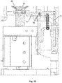
- Figures 12 and 13 show another embodiment of an automated clamping support 30 of the automated system 100 for automatic interchangeability of customized supports 10a, 10b, 10c in the mounting support 40.
- Figure 12 shows the automated clamping support 30, whereby a customized support 10 is firmly held in the complementary mating part 42 of the mounting support 40 while
- Figure 13 shows the automated clamping support 30, whereby the elastic portion 46 is about to be bent outwardly to widen the complementary part 42 of the mounting support 40 to bring the latter from a clamping to an unclamped configuration.
- the automated clamping support 30 comprises a mounting support 40 comprises a longitudinal passage 50 extending from a first lateral side of the mounting support 40 through the mounting support 40 up to the longitudinal slit 44.
- a rod 52 is arranged inside the longitudinal passage 50.
- the rod 52 comprises a first end in abutment against the elastic portion 46 of the mounting support 40 and a second end protruding from the first lateral side of the mounting support 40.
- the second end of the rod 52 may comprise for example a ball bearing 53 configured to cooperate with a lever 74 as explained in detail subsequently.
- the rod 52 comprises an inner threaded portion.
- a through-hole 55 extends from a second lateral side of the mounting support 40, opposite the first lateral side, through the elastic portion 46 to face the inner threaded portion of the rod 52.
- a screw 54 is screwed into the threaded portion of the rod 52 with its screw head 54a resting in the second lateral side of the mounting support 40.
- the automated clamping support 30 further comprises an actuator 60 comprising a piston 72, a lever 74 mounted on a lever support 86 and arranged to be actuated by a distal end of the piston 72 to pivot about an axis of rotation 78.
- the upper portion of the lever support 86 may for example comprise a ball 88 fitted inside a corresponding semi-spherical cavity arranged on the lever 74 to ensure pivoting of the lever 74 about the axis of rotation 78.
- the lever 74 comprises an actuating part 76 designed to cooperate with the second end of the rod 52 protruding from the first lateral side of the mounting support 40 for example with the ball bearing 53 fitted in the end portion of the rod.
- the lever 74 is arranged to cooperate with an elastic member 90, for example a tension spring configured to urge the lever in a non-actuating configuration.
- the lever 74 may comprise for example a first pin 82 and a second pin 96 is mounted on a pin support 94 arranged below the lever 74.
- Each extremity of a tension spring 90 is anchored to the first pin 82, respectively the second pin 96.
- the actuation part 76 of the lever 74 is disengaged from the second end of the rod 52 protruding from the first lateral side of the mounting support 40.
- the tension spring 90 maintains the lever in the position illustrated in this Figure.
- the actuator 60 is actuated such that a stroke is imparted to piston 72 to move the piston preferably in an upward direction so that the distal end of the piston 72 pushes a portion of the lever 74 situated near one extremity and which may comprise a ball-bearing 84 to cooperate with the piston 72.
- the pushing action of the piston 72 rotates the lever 74 to bring its actuating part 76 with the second end of the rod 52 as shown in Figure 13 .
- the robotic arm 120 will then position in the customized support in a compartment 132 of the support storage and grip another customized support 10a, 10b, 10c from another compartment to bring it into the complementary part 42 of the mounting support 40 of the automated clamping support 30.
- the actuator 60 Upon positioning of said another customized support into the complementary part 42 of the mounting support 40, the actuator 60 is actuated such that a stroke is imparted to the piston 72 in a downward direction. At this point, the lever 74 is no longer in contact with the piston which causes the lever 74 to rotate about the axis of rotation 78 in a clockwise direction through the action of the tension spring 92, whereupon the actuating part 76 of the lever 74 is disengaged from the end potion of the rod 52.
- the elastic portion 46 of the mounting support 40 can return in its rest position thereby clamping the customized support in the complementary mating part 42 of the support 40.
- each customized support 10a, 10b, 10c comprises a concave surface with a unique radius of curvature.
- Each support 40a, 40b, 40c is connected to a rotary unit 210 mounting on bearings (not shown).
- the rotary unit 210 comprises a wheel 212 engaging a rack 214.
- the rack 214 is coupled to linear actuator 216 configured to drive in translation the rack 214, thereby rotating the rotary unit 210 to adjust any support 40a, 40b, 40c in correspondence with the spindle of a machine tool, for example a grinding machine.
- the rotary unit is mounted on a rotor of an electrical motor.
- each customized support may form an integral part with a mounting support, wherein each mounted support comprises a unique customized support.
- Each mounted support may be brought by the end-effector of a robotic arm in alignment with a spindle of a machine tool and secured in that position such that a portion of a workpiece blank to be machined is always supported by a customized support of a corresponding mounting support without requiring any height adjustment of the mounting support.
Landscapes
- Engineering & Computer Science (AREA)
- Mechanical Engineering (AREA)
- Jigs For Machine Tools (AREA)
Priority Applications (1)
| Application Number | Priority Date | Filing Date | Title |
|---|---|---|---|
| EP21176447.7A EP4094888A1 (de) | 2021-05-28 | 2021-05-28 | Verfahren zur bearbeitung mehrerer werkstückrohlinge mit einer werkzeugmaschine und ein satz von spezifischen trägern für das verfahren dafür |
Applications Claiming Priority (1)
| Application Number | Priority Date | Filing Date | Title |
|---|---|---|---|
| EP21176447.7A EP4094888A1 (de) | 2021-05-28 | 2021-05-28 | Verfahren zur bearbeitung mehrerer werkstückrohlinge mit einer werkzeugmaschine und ein satz von spezifischen trägern für das verfahren dafür |
Publications (1)
| Publication Number | Publication Date |
|---|---|
| EP4094888A1 true EP4094888A1 (de) | 2022-11-30 |
Family
ID=76180907
Family Applications (1)
| Application Number | Title | Priority Date | Filing Date |
|---|---|---|---|
| EP21176447.7A Withdrawn EP4094888A1 (de) | 2021-05-28 | 2021-05-28 | Verfahren zur bearbeitung mehrerer werkstückrohlinge mit einer werkzeugmaschine und ein satz von spezifischen trägern für das verfahren dafür |
Country Status (1)
| Country | Link |
|---|---|
| EP (1) | EP4094888A1 (de) |
Cited By (1)
| Publication number | Priority date | Publication date | Assignee | Title |
|---|---|---|---|---|
| CN116117521A (zh) * | 2023-03-13 | 2023-05-16 | 重庆福瑞斯自动化设备股份有限公司 | 一种机加装置 |
Citations (1)
| Publication number | Priority date | Publication date | Assignee | Title |
|---|---|---|---|---|
| EP2030727A1 (de) * | 2007-08-31 | 2009-03-04 | Rollomatic S.A. | Präzisionssteuervorrichtung in einer Bearbeitungsmaschine von zylindrischen Werkstücken |
-
2021
- 2021-05-28 EP EP21176447.7A patent/EP4094888A1/de not_active Withdrawn
Patent Citations (1)
| Publication number | Priority date | Publication date | Assignee | Title |
|---|---|---|---|---|
| EP2030727A1 (de) * | 2007-08-31 | 2009-03-04 | Rollomatic S.A. | Präzisionssteuervorrichtung in einer Bearbeitungsmaschine von zylindrischen Werkstücken |
Cited By (1)
| Publication number | Priority date | Publication date | Assignee | Title |
|---|---|---|---|---|
| CN116117521A (zh) * | 2023-03-13 | 2023-05-16 | 重庆福瑞斯自动化设备股份有限公司 | 一种机加装置 |
Similar Documents
| Publication | Publication Date | Title |
|---|---|---|
| KR970008474B1 (ko) | 공작기계의 자동공구교환장치 | |
| EP0890396B1 (de) | Vorrichtung zum automatisch Wechseln von Werkzeugen in einer Biegevorrichtung | |
| JP2007518032A (ja) | カムシャフト製造に関する配置と方法 | |
| JP2010234516A (ja) | ワーククランプ装置及びワーククランプ方法 | |
| CN215100532U (zh) | 减震件装配机械手 | |
| AU719503B2 (en) | Panel cutting machine | |
| CN112882372B (zh) | 用于钟表部件的支持系统 | |
| US7278288B2 (en) | Method and device for transferring a workpiece | |
| KR20090089830A (ko) | 머시닝 센터의 자동 공구교환장치 | |
| CN113198962A (zh) | 一种机床主轴锻造装置 | |
| US7171883B2 (en) | Punching apparatus and the punching unit thereof | |
| JP5875387B2 (ja) | チャック | |
| JP2008535673A (ja) | クランプコレット | |
| US11065732B2 (en) | Setup changing method and machining system | |
| CN113523161B (zh) | 一种刀具自动更换装置、多工位弹簧机及操作方法 | |
| KR102277794B1 (ko) | 고중량 툴 적용이 가능한 툴포트 이송장치를 구비한 공작기계 | |
| JPS62173133A (ja) | クランプ機構 | |
| US20050079024A1 (en) | Chuck device, processing apparatus using the same, and pivot shaft | |
| CN119566879B (zh) | 一种定位调整装置及具有该定位调整装置的五轴机床 | |
| US20240269794A1 (en) | Working head for a machine tool having an interchangeable electrospindle | |
| CN213730555U (zh) | 一种浮动定位装置 | |
| KR20200128799A (ko) | 확장 수납구조를 갖는 머시닝 센터용 자동공구교환장치 | |
| KR102180103B1 (ko) | 언발란스 제품 가공방법 및 가공용 지그 | |
| CN113878323A (zh) | 一种基于力控传感器的双轴孔装配机器人装置和方法 | |
| CN220112838U (zh) | 一种工件辅助上料装置 |
Legal Events
| Date | Code | Title | Description |
|---|---|---|---|
| PUAI | Public reference made under article 153(3) epc to a published international application that has entered the european phase |
Free format text: ORIGINAL CODE: 0009012 |
|
| STAA | Information on the status of an ep patent application or granted ep patent |
Free format text: STATUS: THE APPLICATION HAS BEEN PUBLISHED |
|
| AK | Designated contracting states |
Kind code of ref document: A1 Designated state(s): AL AT BE BG CH CY CZ DE DK EE ES FI FR GB GR HR HU IE IS IT LI LT LU LV MC MK MT NL NO PL PT RO RS SE SI SK SM TR |
|
| STAA | Information on the status of an ep patent application or granted ep patent |
Free format text: STATUS: THE APPLICATION IS DEEMED TO BE WITHDRAWN |
|
| 18D | Application deemed to be withdrawn |
Effective date: 20230531 |