EP4094912B1 - Unité d'insertion d'articles matériels de mobilier dans des panneaux en bois ou similaire - Google Patents
Unité d'insertion d'articles matériels de mobilier dans des panneaux en bois ou similaire Download PDFInfo
- Publication number
- EP4094912B1 EP4094912B1 EP22175203.3A EP22175203A EP4094912B1 EP 4094912 B1 EP4094912 B1 EP 4094912B1 EP 22175203 A EP22175203 A EP 22175203A EP 4094912 B1 EP4094912 B1 EP 4094912B1
- Authority
- EP
- European Patent Office
- Prior art keywords
- feeding
- unit according
- inserting unit
- assembly
- articles
- Prior art date
- Legal status (The legal status is an assumption and is not a legal conclusion. Google has not performed a legal analysis and makes no representation as to the accuracy of the status listed.)
- Active
Links
Images


Classifications
-
- B—PERFORMING OPERATIONS; TRANSPORTING
- B27—WORKING OR PRESERVING WOOD OR SIMILAR MATERIAL; NAILING OR STAPLING MACHINES IN GENERAL
- B27M—WORKING OF WOOD NOT PROVIDED FOR IN SUBCLASSES B27B - B27L; MANUFACTURE OF SPECIFIC WOODEN ARTICLES
- B27M3/00—Manufacture or reconditioning of specific semi-finished or finished articles
- B27M3/0013—Manufacture or reconditioning of specific semi-finished or finished articles of composite or compound articles
- B27M3/0073—Manufacture or reconditioning of specific semi-finished or finished articles of composite or compound articles characterised by nailing, stapling or screwing connections
-
- B—PERFORMING OPERATIONS; TRANSPORTING
- B27—WORKING OR PRESERVING WOOD OR SIMILAR MATERIAL; NAILING OR STAPLING MACHINES IN GENERAL
- B27M—WORKING OF WOOD NOT PROVIDED FOR IN SUBCLASSES B27B - B27L; MANUFACTURE OF SPECIFIC WOODEN ARTICLES
- B27M3/00—Manufacture or reconditioning of specific semi-finished or finished articles
- B27M3/0013—Manufacture or reconditioning of specific semi-finished or finished articles of composite or compound articles
- B27M3/0066—Manufacture or reconditioning of specific semi-finished or finished articles of composite or compound articles characterised by tongue and groove or tap hole connections
Definitions
- the present invention relates to an inserting unit for the insertion of furniture hardware articles into panels made of wood or the like.
- EP 1 982 808 A discloses the preamble of claim 1.
- a drilling/milling/inserting machine of the type comprising a roller or belt supporting device, which defines a substantially horizontal supporting surface for the panels, and extends between a station for loading the panels into the machine and a station for unloading the panels from the machine.
- the machine further comprises at least one machining station provided with an operating unit for machining the panels; at least one inserting station provided with an inserting unit for inserting hardware articles into respective seats formed in the panels by the operating unit; and a feeding device for feeding the panels between the loading station and the unloading station and in a substantially vertical containment plane perpendicular to the supporting surface.
- the feeding device comprises, for example, two gripping members, each of which has two jaws arranged on opposite sides of a path of advancement of the panels in a direction perpendicular to the containment plane.
- the panels are picked up by the two gripping members in the loading station, fed through the machining station and the inserting station, and released into the unloading station.
- the inserting unit comprises an inserting assembly for inserting the hardware articles into the panels; and a feeding assembly for feeding the hardware articles to the inserting assembly.
- the feeding assembly comprises at least one vibrating feeding hopper, which is configured to contain the hardware articles and is provided with a feeding channel for successively transferring the hardware articles from the feeding hopper to the inserting assembly.
- the inserting assembly comprises an inserting device for inserting the hardware articles into the panels; and a transfer device for transferring the hardware articles from the feeding channel to the inserting device.
- the transfer device comprises a plurality of horizontal shuttles and a plurality of vertical shuttles connected to each other so as to transfer each hardware article from the respective feeding channel to the inserting device.
- the inserting device normally comprises a holding member provided with a seat for receiving and holding a hardware article.
- the object of the present invention is to provide an inserting unit for the insertion of furniture hardware articles into panels made of wood or the like, which is free from the drawbacks described above and simple and inexpensive to implement.
- an inserting unit for the insertion of furniture hardware articles into panels made of wood or the like is provided as claimed in the appended claims.
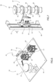
- number 1 indicates, as a whole, an inserting unit for the insertion of furniture hardware articles 2, for example hinges, into panels 3 made of wood or the like.
- the unit 1 comprises an elongated base 4 extending in a horizontal direction 5 and is provided with a feeding device 6, in this case a roller feeding device, defining a supporting surface for the panels 3.
- the panels 3 are arranged on the device 6 in a substantially vertical containment plane, and are fed by the device 6 through an inserting station 7.
- the unit 1 further comprises a feeding assembly 8 in turn comprising a plurality of vibrating feeding hoppers 9 (four hoppers 9 in this case) arranged successively along the base 4 in direction 5, a plurality of vibrating feeding hoppers 10 (two hoppers 10 in this case) aligned with each other in a horizontal direction 11 transverse to direction 5, and a plurality of linear stores 12 parallel to each other and to direction 11.
- a feeding assembly 8 in turn comprising a plurality of vibrating feeding hoppers 9 (four hoppers 9 in this case) arranged successively along the base 4 in direction 5, a plurality of vibrating feeding hoppers 10 (two hoppers 10 in this case) aligned with each other in a horizontal direction 11 transverse to direction 5, and a plurality of linear stores 12 parallel to each other and to direction 11.
- Each hopper 9, 10 houses on the inside a plurality of articles 2 and is configured and set in vibration to feed the articles 2 successively to an output channel 13 extending in a containment plane substantially perpendicular to direction 5 (for the channels 13 of the hoppers 9) and to direction 11 (for the channels 13 of the hoppers 10).
- the stores 12 are inclined with respect to the ground so as to feed the respective articles 2 by gravity at their output ends.
- an inserting assembly 14 comprising, in this case, an inserting device 15 mounted in the station 7 for inserting articles 2 into panels 3, and an industrial robot 16 for transferring the articles between the stores 12 or channels 13 and the device 15.
- the assembly 14 further comprises a guide device 17, which extends along the base 4 in direction 5, is mounted between the base 4, the hoppers 9, and the stores 12, and is slidingly engaged by the robot 16 to allow the robot 16 to move between the hoppers 9, 10, the stores 12, and the station 7.
- the robot 16 has at least four degrees of freedom, is mounted so as to rotate around a substantially vertical rotation axis 18 orthogonal to directions 5 and 11, comprises a plurality of articulated arms 19, and is provided with a holding member 20 mounted on the free end of the last arm 19.
- the member 20 comprises two jaws 21 which are movable between a clamping position and a release position for releasing at least one article 2.
- Each jaw 21 is delimited by a substantially flat front face 22 and is also delimited by a substantially flat holding face 23, which is substantially perpendicular to the face 22 and faces the face 23 of the other jaw 21.
- Each jaw 21 has at least two substantially semicylindrical cavities 24, which are distributed along the face 23 and open outwards where the face 23 is, and is also provided with a flat lug 25 delimited by the face 23.
- each jaw 21 cooperates with the cavities 24 and the lug 25 of the other jaw 21 to grip and hold different types of articles 2.
- Each jaw 21 also has at least two shaped slots 26, which are distributed along the face 22, open outwards where the face 22 is, and cooperate with the slots 26 of the other jaw 21 to house on the inside corresponding parts of different types of articles 2.
- the cavities 24, the lug 25, and the cavities 26 of each jaw 21 are configured so as to cooperate selectively with the cavities 24, the lug 25, and the cavities 26 of the other jaw 21 and allow the member 20 to grip and hold different types of articles 2.
- the inserting device 15 comprises a pair of parallel uprights 27 extending in a vertical direction 28 orthogonal to directions 5 and 11, each supporting a respective vertical slide (not shown) which is movable along the respective upright 27 in direction 28.
- Each vertical slide (not shown) supports a horizontal slide (not shown), which is mounted so as to move in a straight line in direction 11 with respect to the vertical slide (not shown) and supports a holding member 29 designed to receive the articles 2 from the robot 16.
- the member 29 comprises a central hub 30, which is mounted so as to rotate around its own longitudinal axis 31 which is parallel to direction 28, is delimited by a substantially rectangular outer side wall 32, and is provided with a plurality of forks 33 distributed around the axis 31.
- the forks 33 are the same number as the number of faces of the wall 32, are uniformly distributed around the axis 31, and each is configured to receive and hold a respective article 2.
- Each fork 33 is slidably coupled to the hub 30 so as to move in a straight line transverse to direction 28, with respect to the hub 30, and to insert the respective article 2 into the respective panel 3.
- the forks 33 allow the member 29 to receive and hold a plurality of articles 2, in particular different types of articles 2.
- the variant shown in Figure 6 relates to an inserting unit 34 comprising a feeding assembly 35 and an inserting assembly 36.
- the assembly 35 comprises at least one feeding hopper 37 which is absolutely similar to the hoppers 9, 10, an output channel 38 which is absolutely similar to the channels 13, a first bench 39 for receiving trays 40 containing articles 2, and a second bench 41 for receiving the empty trays 40.
- the assembly 36 comprises the inserting device 15 and an anthropomorphic robot 42, which is absolutely similar to the robot 16 and is provided with a holding member 43 which is movable between the channel 38, the benches 39 and 41, and the inserting device 15.
- the hopper 37, the channel 38, the benches 39 and 41, and the robot 42 are mounted on a supporting platform 44 so as to define an assembly 45, which is pre-assembled in the factory of the manufacturer and supplied to the customer with the correct orientation and positioning of the hopper 37, the channel 38, the benches 39 and 41, and the robot 42.
- the variant shown in Figure 7 relates to an inserting unit 46 comprising a feeding assembly 47 and an inserting assembly 48.
- the assembly 47 comprises a plurality of feeding hoppers 49, which are absolutely similar to the hoppers 9, 10, are provided with respective output channels 50, which are absolutely similar to the channels 13, and are arranged at different heights from the ground, in particular aligned with each other in direction 28.
- the assembly 48 comprises an upright 51 substantially parallel to direction 28, a vertical slide 52 slidably coupled to the upright 51 so as to move in a straight line along the upright 51 in direction 28, and an anthropomorphic robot 53 mounted on the slide 52 to move between the channels 50.
- the assembly 48 is further provided with an inserting device 54, in this case comprising a vertical slide 55, which is slidably coupled to the upright 51 so as to move in a straight line along the upright 51 in direction 28, and supports two horizontal slides 56.
- an inserting device 54 in this case comprising a vertical slide 55, which is slidably coupled to the upright 51 so as to move in a straight line along the upright 51 in direction 28, and supports two horizontal slides 56.
- Each slide 56 is coupled to the slide 55 so as to move in a straight line in direction 11 with respect to the slide 55, and is provided with a holding member 57 which is absolutely similar to the members 29.
- the slide 55 is eliminated, and the slides 56 and the members 57 are mounted on the slide 52.
- the inserting unit 46 has some advantages mainly deriving from the fact that the feeding assembly 47 has relatively small dimensions and that the robot 53 is provided with articulated arms of relatively small length and is therefore relatively inexpensive and compact.
Landscapes
- Engineering & Computer Science (AREA)
- Life Sciences & Earth Sciences (AREA)
- Manufacturing & Machinery (AREA)
- Wood Science & Technology (AREA)
- Forests & Forestry (AREA)
- Automatic Assembly (AREA)
Claims (17)
- Unité d'insertion permettant l'insertion d'articles de quincaillerie d'ameublement (2) dans des panneaux (3) constitués de bois ou similaires, l'unité d'insertion comprenant un ensemble d'insertion (14 ; 36 ; 48) pour insérer des articles de quincaillerie (2) dans des panneaux (3) constitués de bois ou similaires ; et un ensemble d'alimentation (8 ; 35 ; 47) pour alimenter les articles de quincaillerie (2) vers l'ensemble d'insertion (14 ; 36 ; 48) ; l'ensemble d'alimentation (8) comprenant une pluralité de magasins (9, 10, 12) pour emmagasiner différents types d'articles de quincaillerie (2) ;
caractérisé en ce que l'ensemble d'insertion (14) comprend un dispositif de transfert comprenant un robot industriel (16 ; 42 ; 53) pour prendre les articles de quincaillerie (2) du magasin (9, 10, 12) et un dispositif d'insertion (15 ; 54) pour recevoir les articles de quincaillerie (2) à partir du robot industriel et les insérer dans les panneaux (3) ; le robot industriel (16 ; 42 ; 53) ayant au moins quatre degrés de liberté ; et le dispositif d'insertion (15 ; 54) comprenant un élément de maintien (29 ; 43 ; 57), qui est pourvu d'une pluralité de sièges (33) pour les différents types d'articles de quincaillerie (2). - Unité d'insertion selon la revendication 1, dans laquelle l'élément de maintien (29 ; 43 ; 57) comprend un moyeu central (30), qui est monté de manière à être en rotation autour d'un axe de rotation (31) ; les sièges (33) étant répartis autour de l'axe de rotation (31).
- Unité d'insertion selon la revendication 2 et comprenant en outre un dispositif de commande pour déplacer le moyeu central (30) autour de l'axe de rotation (31) de manière intermittente.
- Unité d'insertion selon l'une quelconque des revendications précédentes, dans laquelle chaque siège (33) a la forme d'une fourchette.
- Unité d'insertion selon l'une quelconque des revendications précédentes, dans laquelle l'élément de maintien (29 ; 43 ; 57) comprend un moyeu central (30) ; chaque siège (33) étant accouplé au moyeu central (30) de manière à se déplacer entre une position de repos rétractée et une position de fonctionnement extraite, dans laquelle le siège (33) vient en prise avec l'article de quincaillerie (2) dans le panneau (3).
- Unité d'insertion selon la revendication 5, dans laquelle le moyeu central (30) est délimité par une paroi latérale extérieure (32) ; les sièges (33) étant obtenus sur la paroi latérale extérieure (32).
- Unité d'insertion selon l'une quelconque des revendications précédentes, dans laquelle l'ensemble d'alimentation (47) comprend en outre une pluralité de plaques d'alimentation (49), en particulier des trémies d'alimentation, contenant les articles de quincaillerie (2) et, pour chaque plaque d'alimentation (49), un canal d'alimentation (50) respectif permettant de transférer successivement les articles de quincaillerie (2) de la plaque d'alimentation (49) à l'ensemble d'insertion (48) ; les plaques d'alimentation (49) étant disposées à différentes hauteurs par rapport au sol.
- Unité d'insertion selon la revendication 7, dans laquelle le robot industriel (53) est mobile entre les canaux d'alimentation (50) dans une direction (28) sensiblement verticale.
- Unité d'insertion selon la revendication 8, dans laquelle les plaques d'alimentation (49) et les canaux d'alimentation (50) respectifs sont superposés les uns sur les autres dans la direction (28).
- Unité d'insertion selon l'une quelconque des revendications 8 à 9, dans laquelle l'ensemble d'insertion (48) comprend en outre un montant (51) s'étendant dans la direction (28) et en prise de manière coulissante par le robot industriel (53).
- Unité d'insertion selon la revendication 10, dans laquelle le dispositif d'insertion (54) est accouplé de manière coulissante au montant (51) pour se déplacer en une ligne droite dans la direction (28).
- Unité d'insertion selon la revendication 11, dans laquelle le robot industriel (53) et le dispositif d'insertion (54) sont mobiles le long du montant (51) indépendamment l'un de l'autre ou d'un seul tenant l'un avec l'autre.
- Unité d'insertion selon l'une quelconque des revendications précédentes et comprenant en outre une plate-forme de support (44) à laquelle au moins une partie de l'ensemble d'insertion (36) et au moins une partie de l'ensemble d'alimentation (35) sont fixées.
- Unité d'insertion selon la revendication 13, dans laquelle les magasins (9, 10, 12) et le robot industriel (42) sont montés sur la plate-forme de support (44).
- Unité d'insertion selon la revendication 14, dans laquelle l'ensemble d'alimentation (35) comprend une plaque d'alimentation (37), en particulier une trémie d'alimentation (37), montée sur la plate-forme de support (44) et/ou un plateau (40) monté sur la plate-forme de support (44) pour contenir les articles de quincaillerie (2) ; le robot industriel (42) étant monté sur la plate-forme de support (44) pour prendre les articles de quincaillerie (2) de la plaque d'alimentation (37) et/ou du plateau (40).
- Unité d'insertion selon la revendication 15, dans laquelle l'ensemble d'alimentation (35) comprend en outre un premier banc (39) pour accueillir les plateaux (40) contenant les articles de quincaillerie (2) et un second banc (41) pour accueillir les plateaux vides (40) ; lesdits premier et second bancs (39, 41) étant montés sur la plate-forme de support (44).
- Unité d'insertion selon l'une quelconque des revendications 13 à 16, dans laquelle la plate-forme de support (44) repose sur un plancher de support.
Applications Claiming Priority (3)
| Application Number | Priority Date | Filing Date | Title |
|---|---|---|---|
| IT102021000013991A IT202100013991A1 (it) | 2021-05-28 | 2021-05-28 | Unita' inseritrice per l'inserimento di articoli di ferramenta per mobili in pannelli di legno o simili |
| IT102021000013976A IT202100013976A1 (it) | 2021-05-28 | 2021-05-28 | Unita' inseritrice per l'inserimento di articoli di ferramenta per mobili in pannelli di legno o simili |
| IT102021000013970A IT202100013970A1 (it) | 2021-05-28 | 2021-05-28 | Unita' inseritrice per l'inserimento di articoli di ferramenta per mobili in pannelli di legno o simili |
Publications (2)
| Publication Number | Publication Date |
|---|---|
| EP4094912A1 EP4094912A1 (fr) | 2022-11-30 |
| EP4094912B1 true EP4094912B1 (fr) | 2024-12-25 |
Family
ID=81654718
Family Applications (1)
| Application Number | Title | Priority Date | Filing Date |
|---|---|---|---|
| EP22175203.3A Active EP4094912B1 (fr) | 2021-05-28 | 2022-05-24 | Unité d'insertion d'articles matériels de mobilier dans des panneaux en bois ou similaire |
Country Status (1)
| Country | Link |
|---|---|
| EP (1) | EP4094912B1 (fr) |
Family Cites Families (3)
| Publication number | Priority date | Publication date | Assignee | Title |
|---|---|---|---|---|
| DE19922227A1 (de) * | 1999-05-14 | 2000-11-23 | Buerkle Gmbh Robert | Montageanlage für eine Türenendfertigung |
| DE202007005516U1 (de) * | 2007-04-14 | 2008-05-15 | H.I.T. Bertele Gmbh + Co. | Vorrichtung zum Ausbessern von Fehlstellen in einem Holzwerkstück |
| US10471559B2 (en) * | 2017-05-01 | 2019-11-12 | Stafast Products, Inc. | Insertable fastener installation apparatus and method |
-
2022
- 2022-05-24 EP EP22175203.3A patent/EP4094912B1/fr active Active
Also Published As
| Publication number | Publication date |
|---|---|
| EP4094912A1 (fr) | 2022-11-30 |
Similar Documents
| Publication | Publication Date | Title |
|---|---|---|
| CN110980179A (zh) | 自动化生产线及电机转子生产线 | |
| US11298786B2 (en) | Clamping means system capable of automation | |
| US7731644B2 (en) | Device for loading and unloading of a machine tool | |
| CN112888513B (zh) | 带有工具库的金属板折弯机 | |
| US7090559B2 (en) | Ophthalmic lens manufacturing system | |
| JPH11220291A (ja) | プリント回路基板のパックを積み重ねる方法、および加工機用のパック装荷取り外し装置 | |
| CN102099152B (zh) | 自动工具收容机构 | |
| EP1927430A2 (fr) | Dispostif de rotation | |
| EP4094912B1 (fr) | Unité d'insertion d'articles matériels de mobilier dans des panneaux en bois ou similaire | |
| JP2690307B2 (ja) | 物品移送方法及び設備 | |
| JP2942076B2 (ja) | 物品搬送用通箱 | |
| US11040426B2 (en) | Machine tool having a tool spindle and a loading portal | |
| CN113620029A (zh) | 一种智能产线可视化技术应用实训系统 | |
| JP5627120B2 (ja) | 物品搬送装置 | |
| KR101638702B1 (ko) | 자동공구교환장치 | |
| CN115397633B (zh) | 分拣设备的多工具夹头及其操作方法 | |
| EP4504389B1 (fr) | Dispositif et procédé de transfert automatisé de boîtiers | |
| IT202100013991A1 (it) | Unita' inseritrice per l'inserimento di articoli di ferramenta per mobili in pannelli di legno o simili | |
| IT202100013976A1 (it) | Unita' inseritrice per l'inserimento di articoli di ferramenta per mobili in pannelli di legno o simili | |
| CN115489991B (zh) | 数卡装置、定量配发卡片的系统及方法 | |
| IT202100013970A1 (it) | Unita' inseritrice per l'inserimento di articoli di ferramenta per mobili in pannelli di legno o simili | |
| IT202100013964A1 (it) | Unita' inseritrice per l'inserimento di articoli di ferramenta per mobili in pannelli di legno o simili | |
| CN211366090U (zh) | 一种排板设备 | |
| CN211168798U (zh) | 一种循环式托盘供料器 | |
| CN211102635U (zh) | 卡簧套装机 |
Legal Events
| Date | Code | Title | Description |
|---|---|---|---|
| PUAI | Public reference made under article 153(3) epc to a published international application that has entered the european phase |
Free format text: ORIGINAL CODE: 0009012 |
|
| STAA | Information on the status of an ep patent application or granted ep patent |
Free format text: STATUS: THE APPLICATION HAS BEEN PUBLISHED |
|
| AK | Designated contracting states |
Kind code of ref document: A1 Designated state(s): AL AT BE BG CH CY CZ DE DK EE ES FI FR GB GR HR HU IE IS IT LI LT LU LV MC MK MT NL NO PL PT RO RS SE SI SK SM TR |
|
| STAA | Information on the status of an ep patent application or granted ep patent |
Free format text: STATUS: REQUEST FOR EXAMINATION WAS MADE |
|
| STAA | Information on the status of an ep patent application or granted ep patent |
Free format text: STATUS: EXAMINATION IS IN PROGRESS |
|
| 17P | Request for examination filed |
Effective date: 20230419 |
|
| RBV | Designated contracting states (corrected) |
Designated state(s): AL AT BE BG CH CY CZ DE DK EE ES FI FR GB GR HR HU IE IS IT LI LT LU LV MC MK MT NL NO PL PT RO RS SE SI SK SM TR |
|
| 17Q | First examination report despatched |
Effective date: 20230519 |
|
| GRAP | Despatch of communication of intention to grant a patent |
Free format text: ORIGINAL CODE: EPIDOSNIGR1 |
|
| STAA | Information on the status of an ep patent application or granted ep patent |
Free format text: STATUS: GRANT OF PATENT IS INTENDED |
|
| GRAJ | Information related to disapproval of communication of intention to grant by the applicant or resumption of examination proceedings by the epo deleted |
Free format text: ORIGINAL CODE: EPIDOSDIGR1 |
|
| STAA | Information on the status of an ep patent application or granted ep patent |
Free format text: STATUS: EXAMINATION IS IN PROGRESS |
|
| INTG | Intention to grant announced |
Effective date: 20240315 |
|
| INTC | Intention to grant announced (deleted) | ||
| GRAP | Despatch of communication of intention to grant a patent |
Free format text: ORIGINAL CODE: EPIDOSNIGR1 |
|
| STAA | Information on the status of an ep patent application or granted ep patent |
Free format text: STATUS: GRANT OF PATENT IS INTENDED |
|
| GRAJ | Information related to disapproval of communication of intention to grant by the applicant or resumption of examination proceedings by the epo deleted |
Free format text: ORIGINAL CODE: EPIDOSDIGR1 |
|
| GRAP | Despatch of communication of intention to grant a patent |
Free format text: ORIGINAL CODE: EPIDOSNIGR1 |
|
| INTG | Intention to grant announced |
Effective date: 20240605 |
|
| GRAC | Information related to communication of intention to grant a patent modified |
Free format text: ORIGINAL CODE: EPIDOSCIGR1 |
|
| GRAJ | Information related to disapproval of communication of intention to grant by the applicant or resumption of examination proceedings by the epo deleted |
Free format text: ORIGINAL CODE: EPIDOSDIGR1 |
|
| INTG | Intention to grant announced |
Effective date: 20240617 |
|
| GRAP | Despatch of communication of intention to grant a patent |
Free format text: ORIGINAL CODE: EPIDOSNIGR1 |
|
| INTG | Intention to grant announced |
Effective date: 20240701 |
|
| INTG | Intention to grant announced |
Effective date: 20240719 |
|
| GRAS | Grant fee paid |
Free format text: ORIGINAL CODE: EPIDOSNIGR3 |
|
| GRAA | (expected) grant |
Free format text: ORIGINAL CODE: 0009210 |
|
| STAA | Information on the status of an ep patent application or granted ep patent |
Free format text: STATUS: THE PATENT HAS BEEN GRANTED |
|
| AK | Designated contracting states |
Kind code of ref document: B1 Designated state(s): AL AT BE BG CH CY CZ DE DK EE ES FI FR GB GR HR HU IE IS IT LI LT LU LV MC MK MT NL NO PL PT RO RS SE SI SK SM TR |
|
| REG | Reference to a national code |
Ref country code: GB Ref legal event code: FG4D |
|
| REG | Reference to a national code |
Ref country code: CH Ref legal event code: EP |
|
| REG | Reference to a national code |
Ref country code: DE Ref legal event code: R096 Ref document number: 602022009000 Country of ref document: DE |
|
| REG | Reference to a national code |
Ref country code: IE Ref legal event code: FG4D |
|
| REG | Reference to a national code |
Ref country code: LT Ref legal event code: MG9D |
|
| PG25 | Lapsed in a contracting state [announced via postgrant information from national office to epo] |
Ref country code: FI Free format text: LAPSE BECAUSE OF FAILURE TO SUBMIT A TRANSLATION OF THE DESCRIPTION OR TO PAY THE FEE WITHIN THE PRESCRIBED TIME-LIMIT Effective date: 20241225 |
|
| PG25 | Lapsed in a contracting state [announced via postgrant information from national office to epo] |
Ref country code: BG Free format text: LAPSE BECAUSE OF FAILURE TO SUBMIT A TRANSLATION OF THE DESCRIPTION OR TO PAY THE FEE WITHIN THE PRESCRIBED TIME-LIMIT Effective date: 20241225 |
|
| PG25 | Lapsed in a contracting state [announced via postgrant information from national office to epo] |
Ref country code: NO Free format text: LAPSE BECAUSE OF FAILURE TO SUBMIT A TRANSLATION OF THE DESCRIPTION OR TO PAY THE FEE WITHIN THE PRESCRIBED TIME-LIMIT Effective date: 20250325 |
|
| PG25 | Lapsed in a contracting state [announced via postgrant information from national office to epo] |
Ref country code: LV Free format text: LAPSE BECAUSE OF FAILURE TO SUBMIT A TRANSLATION OF THE DESCRIPTION OR TO PAY THE FEE WITHIN THE PRESCRIBED TIME-LIMIT Effective date: 20241225 Ref country code: GR Free format text: LAPSE BECAUSE OF FAILURE TO SUBMIT A TRANSLATION OF THE DESCRIPTION OR TO PAY THE FEE WITHIN THE PRESCRIBED TIME-LIMIT Effective date: 20250326 |
|
| PG25 | Lapsed in a contracting state [announced via postgrant information from national office to epo] |
Ref country code: RS Free format text: LAPSE BECAUSE OF FAILURE TO SUBMIT A TRANSLATION OF THE DESCRIPTION OR TO PAY THE FEE WITHIN THE PRESCRIBED TIME-LIMIT Effective date: 20250325 |
|
| REG | Reference to a national code |
Ref country code: NL Ref legal event code: MP Effective date: 20241225 |
|
| PG25 | Lapsed in a contracting state [announced via postgrant information from national office to epo] |
Ref country code: NL Free format text: LAPSE BECAUSE OF FAILURE TO SUBMIT A TRANSLATION OF THE DESCRIPTION OR TO PAY THE FEE WITHIN THE PRESCRIBED TIME-LIMIT Effective date: 20241225 |
|
| PG25 | Lapsed in a contracting state [announced via postgrant information from national office to epo] |
Ref country code: SM Free format text: LAPSE BECAUSE OF FAILURE TO SUBMIT A TRANSLATION OF THE DESCRIPTION OR TO PAY THE FEE WITHIN THE PRESCRIBED TIME-LIMIT Effective date: 20241225 |
|
| PG25 | Lapsed in a contracting state [announced via postgrant information from national office to epo] |
Ref country code: PL Free format text: LAPSE BECAUSE OF FAILURE TO SUBMIT A TRANSLATION OF THE DESCRIPTION OR TO PAY THE FEE WITHIN THE PRESCRIBED TIME-LIMIT Effective date: 20241225 |
|
| PGFP | Annual fee paid to national office [announced via postgrant information from national office to epo] |
Ref country code: DE Payment date: 20250528 Year of fee payment: 4 |
|
| PG25 | Lapsed in a contracting state [announced via postgrant information from national office to epo] |
Ref country code: ES Free format text: LAPSE BECAUSE OF FAILURE TO SUBMIT A TRANSLATION OF THE DESCRIPTION OR TO PAY THE FEE WITHIN THE PRESCRIBED TIME-LIMIT Effective date: 20241225 |
|
| PG25 | Lapsed in a contracting state [announced via postgrant information from national office to epo] |
Ref country code: IS Free format text: LAPSE BECAUSE OF FAILURE TO SUBMIT A TRANSLATION OF THE DESCRIPTION OR TO PAY THE FEE WITHIN THE PRESCRIBED TIME-LIMIT Effective date: 20250425 |
|
| PGFP | Annual fee paid to national office [announced via postgrant information from national office to epo] |
Ref country code: IT Payment date: 20250531 Year of fee payment: 4 |
|
| PG25 | Lapsed in a contracting state [announced via postgrant information from national office to epo] |
Ref country code: PT Free format text: LAPSE BECAUSE OF FAILURE TO SUBMIT A TRANSLATION OF THE DESCRIPTION OR TO PAY THE FEE WITHIN THE PRESCRIBED TIME-LIMIT Effective date: 20250428 |
|
| PG25 | Lapsed in a contracting state [announced via postgrant information from national office to epo] |
Ref country code: EE Free format text: LAPSE BECAUSE OF FAILURE TO SUBMIT A TRANSLATION OF THE DESCRIPTION OR TO PAY THE FEE WITHIN THE PRESCRIBED TIME-LIMIT Effective date: 20241225 |
|
| PG25 | Lapsed in a contracting state [announced via postgrant information from national office to epo] |
Ref country code: RO Free format text: LAPSE BECAUSE OF FAILURE TO SUBMIT A TRANSLATION OF THE DESCRIPTION OR TO PAY THE FEE WITHIN THE PRESCRIBED TIME-LIMIT Effective date: 20241225 |
|
| PGFP | Annual fee paid to national office [announced via postgrant information from national office to epo] |
Ref country code: AT Payment date: 20250721 Year of fee payment: 4 |
|
| PG25 | Lapsed in a contracting state [announced via postgrant information from national office to epo] |
Ref country code: SK Free format text: LAPSE BECAUSE OF FAILURE TO SUBMIT A TRANSLATION OF THE DESCRIPTION OR TO PAY THE FEE WITHIN THE PRESCRIBED TIME-LIMIT Effective date: 20241225 |
|
| PG25 | Lapsed in a contracting state [announced via postgrant information from national office to epo] |
Ref country code: CZ Free format text: LAPSE BECAUSE OF FAILURE TO SUBMIT A TRANSLATION OF THE DESCRIPTION OR TO PAY THE FEE WITHIN THE PRESCRIBED TIME-LIMIT Effective date: 20241225 |
|
| PG25 | Lapsed in a contracting state [announced via postgrant information from national office to epo] |
Ref country code: SE Free format text: LAPSE BECAUSE OF FAILURE TO SUBMIT A TRANSLATION OF THE DESCRIPTION OR TO PAY THE FEE WITHIN THE PRESCRIBED TIME-LIMIT Effective date: 20241225 |
|
| REG | Reference to a national code |
Ref country code: DE Ref legal event code: R097 Ref document number: 602022009000 Country of ref document: DE |
|
| PG25 | Lapsed in a contracting state [announced via postgrant information from national office to epo] |
Ref country code: DK Free format text: LAPSE BECAUSE OF FAILURE TO SUBMIT A TRANSLATION OF THE DESCRIPTION OR TO PAY THE FEE WITHIN THE PRESCRIBED TIME-LIMIT Effective date: 20241225 |
|
| PLBE | No opposition filed within time limit |
Free format text: ORIGINAL CODE: 0009261 |
|
| STAA | Information on the status of an ep patent application or granted ep patent |
Free format text: STATUS: NO OPPOSITION FILED WITHIN TIME LIMIT |
|
| REG | Reference to a national code |
Ref country code: CH Ref legal event code: L10 Free format text: ST27 STATUS EVENT CODE: U-0-0-L10-L00 (AS PROVIDED BY THE NATIONAL OFFICE) Effective date: 20251105 |
|
| 26N | No opposition filed |
Effective date: 20250926 |
|
| REG | Reference to a national code |
Ref country code: CH Ref legal event code: H13 Free format text: ST27 STATUS EVENT CODE: U-0-0-H10-H13 (AS PROVIDED BY THE NATIONAL OFFICE) Effective date: 20251223 |
|
| PG25 | Lapsed in a contracting state [announced via postgrant information from national office to epo] |
Ref country code: LU Free format text: LAPSE BECAUSE OF NON-PAYMENT OF DUE FEES Effective date: 20250524 |
|
| PG25 | Lapsed in a contracting state [announced via postgrant information from national office to epo] |
Ref country code: CH Free format text: LAPSE BECAUSE OF NON-PAYMENT OF DUE FEES Effective date: 20250531 |
|
| REG | Reference to a national code |
Ref country code: BE Ref legal event code: MM Effective date: 20250531 |
|
| PG25 | Lapsed in a contracting state [announced via postgrant information from national office to epo] |
Ref country code: MC Free format text: LAPSE BECAUSE OF FAILURE TO SUBMIT A TRANSLATION OF THE DESCRIPTION OR TO PAY THE FEE WITHIN THE PRESCRIBED TIME-LIMIT Effective date: 20241225 |
|
| REG | Reference to a national code |
Ref country code: AT Ref legal event code: UEP Ref document number: 1753798 Country of ref document: AT Kind code of ref document: T Effective date: 20241225 |
|
| PG25 | Lapsed in a contracting state [announced via postgrant information from national office to epo] |
Ref country code: IE Free format text: LAPSE BECAUSE OF NON-PAYMENT OF DUE FEES Effective date: 20250524 |
|
| PG25 | Lapsed in a contracting state [announced via postgrant information from national office to epo] |
Ref country code: HR Free format text: LAPSE BECAUSE OF FAILURE TO SUBMIT A TRANSLATION OF THE DESCRIPTION OR TO PAY THE FEE WITHIN THE PRESCRIBED TIME-LIMIT Effective date: 20241225 |
|
| PG25 | Lapsed in a contracting state [announced via postgrant information from national office to epo] |
Ref country code: BE Free format text: LAPSE BECAUSE OF NON-PAYMENT OF DUE FEES Effective date: 20250531 |
|
| PG25 | Lapsed in a contracting state [announced via postgrant information from national office to epo] |
Ref country code: FR Free format text: LAPSE BECAUSE OF NON-PAYMENT OF DUE FEES Effective date: 20250531 |