EP4094921A1 - Vorrichtung mit dichtung zum verschliessen von löchern gegen den durchgang eines mediums - Google Patents
Vorrichtung mit dichtung zum verschliessen von löchern gegen den durchgang eines mediums Download PDFInfo
- Publication number
- EP4094921A1 EP4094921A1 EP21176235.6A EP21176235A EP4094921A1 EP 4094921 A1 EP4094921 A1 EP 4094921A1 EP 21176235 A EP21176235 A EP 21176235A EP 4094921 A1 EP4094921 A1 EP 4094921A1
- Authority
- EP
- European Patent Office
- Prior art keywords
- threaded
- sealing
- seal
- screwing
- plug
- Prior art date
- Legal status (The legal status is an assumption and is not a legal conclusion. Google has not performed a legal analysis and makes no representation as to the accuracy of the status listed.)
- Withdrawn
Links
- 238000007789 sealing Methods 0.000 claims abstract description 46
- 239000000463 material Substances 0.000 claims description 3
- 239000007788 liquid Substances 0.000 claims 2
- 241001105097 Trox Species 0.000 claims 1
- 238000000034 method Methods 0.000 claims 1
- 238000001816 cooling Methods 0.000 abstract description 13
- 238000010438 heat treatment Methods 0.000 abstract description 8
- 238000009434 installation Methods 0.000 abstract description 3
- 239000000243 solution Substances 0.000 description 7
- XLYOFNOQVPJJNP-UHFFFAOYSA-N water Substances O XLYOFNOQVPJJNP-UHFFFAOYSA-N 0.000 description 4
- 238000004519 manufacturing process Methods 0.000 description 3
- 239000008187 granular material Substances 0.000 description 2
- 238000001746 injection moulding Methods 0.000 description 2
- 229910000831 Steel Inorganic materials 0.000 description 1
- 238000010276 construction Methods 0.000 description 1
- 238000003780 insertion Methods 0.000 description 1
- 230000037431 insertion Effects 0.000 description 1
- 239000010959 steel Substances 0.000 description 1
Images



Classifications
-
- B—PERFORMING OPERATIONS; TRANSPORTING
- B29—WORKING OF PLASTICS; WORKING OF SUBSTANCES IN A PLASTIC STATE IN GENERAL
- B29C—SHAPING OR JOINING OF PLASTICS; SHAPING OF MATERIAL IN A PLASTIC STATE, NOT OTHERWISE PROVIDED FOR; AFTER-TREATMENT OF THE SHAPED PRODUCTS, e.g. REPAIRING
- B29C45/00—Injection moulding, i.e. forcing the required volume of moulding material through a nozzle into a closed mould; Apparatus therefor
- B29C45/17—Component parts, details or accessories; Auxiliary operations
- B29C45/26—Moulds
- B29C45/2602—Mould construction elements
-
- B—PERFORMING OPERATIONS; TRANSPORTING
- B29—WORKING OF PLASTICS; WORKING OF SUBSTANCES IN A PLASTIC STATE IN GENERAL
- B29C—SHAPING OR JOINING OF PLASTICS; SHAPING OF MATERIAL IN A PLASTIC STATE, NOT OTHERWISE PROVIDED FOR; AFTER-TREATMENT OF THE SHAPED PRODUCTS, e.g. REPAIRING
- B29C33/00—Moulds or cores; Details thereof or accessories therefor
- B29C33/02—Moulds or cores; Details thereof or accessories therefor with incorporated heating or cooling means
- B29C33/04—Moulds or cores; Details thereof or accessories therefor with incorporated heating or cooling means using liquids, gas or steam
-
- B—PERFORMING OPERATIONS; TRANSPORTING
- B29—WORKING OF PLASTICS; WORKING OF SUBSTANCES IN A PLASTIC STATE IN GENERAL
- B29C—SHAPING OR JOINING OF PLASTICS; SHAPING OF MATERIAL IN A PLASTIC STATE, NOT OTHERWISE PROVIDED FOR; AFTER-TREATMENT OF THE SHAPED PRODUCTS, e.g. REPAIRING
- B29C45/00—Injection moulding, i.e. forcing the required volume of moulding material through a nozzle into a closed mould; Apparatus therefor
- B29C45/17—Component parts, details or accessories; Auxiliary operations
- B29C45/72—Heating or cooling
- B29C45/73—Heating or cooling of the mould
- B29C45/7312—Construction of heating or cooling fluid flow channels
-
- F—MECHANICAL ENGINEERING; LIGHTING; HEATING; WEAPONS; BLASTING
- F16—ENGINEERING ELEMENTS AND UNITS; GENERAL MEASURES FOR PRODUCING AND MAINTAINING EFFECTIVE FUNCTIONING OF MACHINES OR INSTALLATIONS; THERMAL INSULATION IN GENERAL
- F16L—PIPES; JOINTS OR FITTINGS FOR PIPES; SUPPORTS FOR PIPES, CABLES OR PROTECTIVE TUBING; MEANS FOR THERMAL INSULATION IN GENERAL
- F16L55/00—Devices or appurtenances for use in, or in connection with, pipes or pipe systems
- F16L55/10—Means for stopping flow in pipes or hoses
- F16L55/11—Plugs
- F16L55/1108—Plugs fixed by screwing or by means of a screw-threaded ring
Definitions
- This invention is generally related to the field of plastic injection moulding, a production method of plastic items, for which plastic granulate is melted down and injected into the hollow cavity of a mould.
- the molten plastic is cooled/heated by a temperature control system, so that the injected part can be removed from the mould.
- This production method is best suited for the mass production of plastic components of every kind.
- an injection moulding tool contains two mould halves: a nozzle side and an ejector side. Inside the mould halves are the gating system, the cavity inserts, the slide, the ejector elements and the cooling unit. More specifically, due to the molten plastic granulate; a high degree of warmth is produced in the entire mould, which results in long cycle times, but which can be greatly reduced through cooling. Therefore, cooling circuits are created with the help of drill holes and plugs in order to cool down partial areas of the mould.
- Hydraulic holes connect hydraulic cylinders, which are mounted in the ejector packet or the mould plate, and which push the entire ejector packet to the front when the tool is opened.
- the closed circle with supply and return to the cylinders creates sufficient pressure in order to eject the finished component during extension.
- Closing and sealing the hydraulic and cooling / heating holes is necessary for flawless functioning during the pressure build-up of the hydraulic cylinder and the cooling / heating of the mould.
- circuit holes are closed and securely sealed. They are created through several individual holes and together lead to one or more circuits through which a medium (water, oil or similar) passes and is used for cooling / heating a mold or other equipment.
- a medium water, oil or similar
- Closing the holes and sealing is done through the sealing surfaces between 0° ⁇ 90°, the threaded plug with seal, and threaded stepped hole that has a chamfer for easier installation, which ensures the correct operation of the cooling circuits and hydraulic.
- the groove care in which the sealing / gasket is located prevents the sealing / gasket from being destroyed when tightening or screwing.
- Closing and sealing the hydraulic and cooling / heating holes is necessary for flawless functioning during the pressure build-up of the hydraulic cylinder and the cooling / heating of the mould.
- the operating principle of the present invention is that the threaded plug with seal is much more compact in terms of its dimensions compared to state-of-the-art solutions. This is possible by the presence of the collar that is used as a slanted sealing surface between 0° ⁇ 90° and is provided with a groove. In the groove there is a seal, which can be elastic or plastic. In order to be able to assemble them, means for screwing and a thread are available.
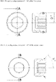
- the threaded plug with seal ensures the sealing function when screwing in, thanks to the groove and the seal, which is located in the variable sealing surface between 0° ⁇ 90° of the collar. That is the reason why the drawings present two variants of the threaded plug, one for an angle of 0° and the other for an angle of 45°, but it can be manufactured for any angle between 0° ⁇ 90°.
- the seal is pressed from the bore surface into the groove or against the variable sealing surface between 0° ⁇ 90° of the plug so that they mutually adapt to their surface structure and thus do not let any medium through.
- the object of the present invention is to ensure that the circuit holes are closed and securely sealed. They are created through several individual holes and together lead to one or more circuits through which an environment (water, oil, steam or similar) passes and is used for cooling / heating a mold or other equipment.
- an environment water, oil, steam or similar
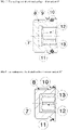
- the solution can also be used in high pressure hydraulic circuits. Closing the holes and sealing is done through the sealing surfaces (5, 10, FIG. 7, 8 , 9, 10 ), between 0° ⁇ 90 °, through the threaded plug with seal (7, FIG. 7, 8 ) and the threaded and stepped hole that has a chamfer for easier installation (2, FIG. 11 , 12 ), which ensures the correct operation of the cooling / heating circuits and hydraulic systems.
- the groove (13, FIG. 7, 8 ) in which the sealing ring / gasket is located (11, FIG. 7, 8 ) prevents the sealing ring / gasket from being extinguished when tightening or screwing.
- the threaded plug with seal (7, FIG. 7, 8 ) has a sealing ring / gasket (11, FIG. 7, 8 ) mounted which is screwed into a hole with thread and a chamfer (2, FIG. 11 , 12 )
- the outer thread (8, FIG. 7, 8 ) from the sealed threaded plug (7, FIG. 7, 8 ) corresponds to the inner thread (3, FIG. 11 , 12 ) and a hexagonal/TORX key corresponds to the inner hexagon/TORX, used for screwing (12, FIG. 7, 8 ).
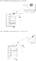
- the gasket When pressure is accumulated in the circuits, the gasket (11, FIG. 7, 8 ) deforms so that it is pressed in the space between (5 and 10, FIG. 11 , 12 ). Now it can be completely sealed and does not allow any medium to pass (e.g. water, oil, steam or something similar).
- any medium to pass e.g. water, oil, steam or something similar.
- the sealing By tightening, the sealing can be done through the sealing surfaces (5 and 10 FIG. 11 , 12 ) and the sealing (11, FIG. 7, 8 ). But only when the threaded plug (7, FIG. 7, 8 ) is completely screwed into the step hole (2, FIG. 11 , 12 ), the sealing ring / gasket (11, FIG. 7, 8 ) is tightened between the sealing surfaces.
- the sealing ring / gasket fits between them and does not allow any medium to pass (e.g. water, oil, steam or something similar) ( FIG. 11 , 12 ).
- the present invention provides improved sealing on the variable sealing surfaces (0°-90°) - e.g. closing a cooling or hydraulic circuit, approximative 20% smaller diameter, no protrusion of the screw plug over the tool edge, despite the reduced total length, approximative 40% economy of the total length compared to state-of-the-art, but nonetheless sufficient the same maximum pressure (up to 400 bar).
- the present invention is extremely compact designed, has multiple use compared to previous solutions with seal, the seal provides complete sealing after disconnection and greater quantities can be produced from the same amount of material.
- the present invention provides higher heat resistance compared to previous solutions from the state-of-the-art (up to 200°C) and is designed for pressures up to 400 bar, despite the compact dimensions of its diameter and length.
Landscapes
- Engineering & Computer Science (AREA)
- Mechanical Engineering (AREA)
- General Engineering & Computer Science (AREA)
- Manufacturing & Machinery (AREA)
- Physics & Mathematics (AREA)
- Fluid Mechanics (AREA)
- Pressure Vessels And Lids Thereof (AREA)
Priority Applications (1)
| Application Number | Priority Date | Filing Date | Title |
|---|---|---|---|
| EP21176235.6A EP4094921A1 (de) | 2021-05-27 | 2021-05-27 | Vorrichtung mit dichtung zum verschliessen von löchern gegen den durchgang eines mediums |
Applications Claiming Priority (1)
| Application Number | Priority Date | Filing Date | Title |
|---|---|---|---|
| EP21176235.6A EP4094921A1 (de) | 2021-05-27 | 2021-05-27 | Vorrichtung mit dichtung zum verschliessen von löchern gegen den durchgang eines mediums |
Publications (1)
| Publication Number | Publication Date |
|---|---|
| EP4094921A1 true EP4094921A1 (de) | 2022-11-30 |
Family
ID=76159339
Family Applications (1)
| Application Number | Title | Priority Date | Filing Date |
|---|---|---|---|
| EP21176235.6A Withdrawn EP4094921A1 (de) | 2021-05-27 | 2021-05-27 | Vorrichtung mit dichtung zum verschliessen von löchern gegen den durchgang eines mediums |
Country Status (1)
| Country | Link |
|---|---|
| EP (1) | EP4094921A1 (de) |
Citations (8)
| Publication number | Priority date | Publication date | Assignee | Title |
|---|---|---|---|---|
| EP0069866A1 (de) * | 1981-06-15 | 1983-01-19 | Heinrich Huth | Verschlusselement für Bohrungen |
| EP0806369A1 (de) * | 1996-05-06 | 1997-11-12 | Rieke Corporation | Veschlussstopfen mit integrierter,geformter Dichtung |
| DE102008039701A1 (de) * | 2008-08-26 | 2010-03-04 | Klaus Heinrichs | Formdichtring |
| EP2423558A1 (de) * | 2010-08-31 | 2012-02-29 | Ermanno Balzi | Dichtungselement für die Enden von Leitungen in Formkühlkreisen, Dichtungskit für Leitungen in Formkühlkreisen und zugehöriges Verfahren |
| EP2871138A1 (de) * | 2013-11-07 | 2015-05-13 | DBI Plastics A/S | Gewindestopfen mit einem Dichtungsring |
| EP3086001A1 (de) * | 2015-04-22 | 2016-10-26 | Johannes Schäfer vormals Stettiner Schraubenwerke GmbH & Co. KG | Verschlussschraube |
| CN205689937U (zh) * | 2016-06-23 | 2016-11-16 | 绍兴上虞中塘电器五金厂 | 一种螺塞接头 |
| EP3353460A1 (de) * | 2015-09-25 | 2018-08-01 | Voss Automotive GmbH | Verschlussschraube |
-
2021
- 2021-05-27 EP EP21176235.6A patent/EP4094921A1/de not_active Withdrawn
Patent Citations (8)
| Publication number | Priority date | Publication date | Assignee | Title |
|---|---|---|---|---|
| EP0069866A1 (de) * | 1981-06-15 | 1983-01-19 | Heinrich Huth | Verschlusselement für Bohrungen |
| EP0806369A1 (de) * | 1996-05-06 | 1997-11-12 | Rieke Corporation | Veschlussstopfen mit integrierter,geformter Dichtung |
| DE102008039701A1 (de) * | 2008-08-26 | 2010-03-04 | Klaus Heinrichs | Formdichtring |
| EP2423558A1 (de) * | 2010-08-31 | 2012-02-29 | Ermanno Balzi | Dichtungselement für die Enden von Leitungen in Formkühlkreisen, Dichtungskit für Leitungen in Formkühlkreisen und zugehöriges Verfahren |
| EP2871138A1 (de) * | 2013-11-07 | 2015-05-13 | DBI Plastics A/S | Gewindestopfen mit einem Dichtungsring |
| EP3086001A1 (de) * | 2015-04-22 | 2016-10-26 | Johannes Schäfer vormals Stettiner Schraubenwerke GmbH & Co. KG | Verschlussschraube |
| EP3353460A1 (de) * | 2015-09-25 | 2018-08-01 | Voss Automotive GmbH | Verschlussschraube |
| CN205689937U (zh) * | 2016-06-23 | 2016-11-16 | 绍兴上虞中塘电器五金厂 | 一种螺塞接头 |
Similar Documents
| Publication | Publication Date | Title |
|---|---|---|
| CA2262175C (en) | Injection molding apparatus with removable nozzle seal | |
| CA1193818A (en) | Hydraulically actuated injection molding system with alternate hydraulic connections | |
| US5374182A (en) | Hot runner manifold bushing | |
| US5955121A (en) | Injection molding apparatus with insert secured through the manifold to a nozzle | |
| US6860732B2 (en) | Thermal seal between manifold and nozzle | |
| CA1213706A (en) | Injection molding valve gated system | |
| US7600995B2 (en) | Hot runner having reduced valve-stem drool | |
| US5494433A (en) | Injection molding hot tip side gate seal having a circumferential rim | |
| US6095790A (en) | Injection molding cylindrical manifold insert and method | |
| US6318990B1 (en) | Injection molding nozzle apparatus | |
| US6162043A (en) | Injection molding nozzle screwed into a mounting base | |
| CA2535422C (en) | Improved adjustable valve pin assembly and method | |
| US3935972A (en) | Pressure actuated nozzle valve for injection molding units | |
| CA2837637C (en) | Injection molding nozzle with dynamic seal | |
| US5980236A (en) | Injection molding apparatus having nozzles with elongated mounting flanges | |
| US6354826B1 (en) | Pin for gas assisted injection molding system | |
| CA2250598A1 (en) | Apparatus for locating and sealing an injection molding nozzle | |
| KR101628243B1 (ko) | 핫러너 장치 | |
| KR200440823Y1 (ko) | 합성수지로 된 연결부를 갖는 밸브 | |
| JP2586010Y2 (ja) | 成形金型装置 | |
| US20100278964A1 (en) | Injection Molding Nozzle | |
| CN222112366U (zh) | 喷嘴装置和微滴喷射装置 | |
| CA2233492A1 (en) | Injection molding nozzle arrangement |
Legal Events
| Date | Code | Title | Description |
|---|---|---|---|
| PUAI | Public reference made under article 153(3) epc to a published international application that has entered the european phase |
Free format text: ORIGINAL CODE: 0009012 |
|
| STAA | Information on the status of an ep patent application or granted ep patent |
Free format text: STATUS: THE APPLICATION HAS BEEN PUBLISHED |
|
| AK | Designated contracting states |
Kind code of ref document: A1 Designated state(s): AL AT BE BG CH CY CZ DE DK EE ES FI FR GB GR HR HU IE IS IT LI LT LU LV MC MK MT NL NO PL PT RO RS SE SI SK SM TR |
|
| STAA | Information on the status of an ep patent application or granted ep patent |
Free format text: STATUS: REQUEST FOR EXAMINATION WAS MADE |
|
| 17P | Request for examination filed |
Effective date: 20230529 |
|
| RBV | Designated contracting states (corrected) |
Designated state(s): AL AT BE BG CH CY CZ DE DK EE ES FI FR GB GR HR HU IE IS IT LI LT LU LV MC MK MT NL NO PL PT RO RS SE SI SK SM TR |
|
| STAA | Information on the status of an ep patent application or granted ep patent |
Free format text: STATUS: THE APPLICATION IS DEEMED TO BE WITHDRAWN |
|
| 18D | Application deemed to be withdrawn |
Effective date: 20241203 |