EP4094953B1 - Jante de véhicule pourvue d'élément de liaison pour un dispositif de maintien destiné à l'application d'un dispositif antiglissement - Google Patents
Jante de véhicule pourvue d'élément de liaison pour un dispositif de maintien destiné à l'application d'un dispositif antiglissement Download PDFInfo
- Publication number
- EP4094953B1 EP4094953B1 EP22174991.4A EP22174991A EP4094953B1 EP 4094953 B1 EP4094953 B1 EP 4094953B1 EP 22174991 A EP22174991 A EP 22174991A EP 4094953 B1 EP4094953 B1 EP 4094953B1
- Authority
- EP
- European Patent Office
- Prior art keywords
- vehicle rim
- vehicle
- rim
- holding device
- fastening
- Prior art date
- Legal status (The legal status is an assumption and is not a legal conclusion. Google has not performed a legal analysis and makes no representation as to the accuracy of the status listed.)
- Active
Links
Images


Classifications
-
- B—PERFORMING OPERATIONS; TRANSPORTING
- B60—VEHICLES IN GENERAL
- B60B—VEHICLE WHEELS; CASTORS; AXLES FOR WHEELS OR CASTORS; INCREASING WHEEL ADHESION
- B60B15/00—Wheels or wheel attachments designed for increasing traction
- B60B15/18—Wheels with ground-engaging plate-like shoes
- B60B15/20—Wheels with ground-engaging plate-like shoes with resiliently-mounted shoes, e.g. on a spider
-
- B—PERFORMING OPERATIONS; TRANSPORTING
- B60—VEHICLES IN GENERAL
- B60B—VEHICLE WHEELS; CASTORS; AXLES FOR WHEELS OR CASTORS; INCREASING WHEEL ADHESION
- B60B15/00—Wheels or wheel attachments designed for increasing traction
- B60B15/18—Wheels with ground-engaging plate-like shoes
- B60B15/22—Wheels with ground-engaging plate-like shoes connected by links to the hub
-
- B—PERFORMING OPERATIONS; TRANSPORTING
- B60—VEHICLES IN GENERAL
- B60B—VEHICLE WHEELS; CASTORS; AXLES FOR WHEELS OR CASTORS; INCREASING WHEEL ADHESION
- B60B3/00—Disc wheels, i.e. wheels with load-supporting disc body
- B60B3/002—Disc wheels, i.e. wheels with load-supporting disc body characterised by the shape of the disc
- B60B3/004—Disc wheels, i.e. wheels with load-supporting disc body characterised by the shape of the disc in the hub section
-
- B—PERFORMING OPERATIONS; TRANSPORTING
- B60—VEHICLES IN GENERAL
- B60B—VEHICLE WHEELS; CASTORS; AXLES FOR WHEELS OR CASTORS; INCREASING WHEEL ADHESION
- B60B2900/00—Purpose of invention
- B60B2900/50—Improvement of
- B60B2900/551—Handling of obstacles or difficult terrains
-
- B—PERFORMING OPERATIONS; TRANSPORTING
- B60—VEHICLES IN GENERAL
- B60B—VEHICLE WHEELS; CASTORS; AXLES FOR WHEELS OR CASTORS; INCREASING WHEEL ADHESION
- B60B2900/00—Purpose of invention
- B60B2900/70—Adaptation for
- B60B2900/721—Use under adverse external conditions
Definitions
- the invention relates to a vehicle rim for a motor vehicle or for a motor vehicle trailer, wherein the vehicle rim has a fastening device for fastening the vehicle rim to a wheel hub or to a wheel hub flange.
- Vehicle rims are known to be components of vehicle wheels. In adverse conditions, for example on snow-covered or muddy surfaces, it may be necessary to attach an anti-skid device to the vehicle wheel. Some anti-skid devices are pulled over the tire. Others, in particular self-tightening anti-skid devices, are usually attached to a wheel bolt or a wheel nut.
- the wheel bolt or the wheel nut can be part of a fastening device for attaching the vehicle rim to the wheel hub or the wheel hub flange.
- the fastening device of the vehicle rim is formed by several holes through which the wheel bolts can protrude.
- the fastening device can be formed by a central hole for a central locking screw.
- the anti-skid device is usually attached using a holding device which is attached to a wheel bolt at one end and has an arm at the other end for attaching the anti-skid device.
- a self-tightening anti-skid device from the applicant is known, for example, from DE 10 2009 004 807 A1 known.
- the DE3844494A shows a generic vehicle rim.
- the holding device can be attached directly to the vehicle rim.
- the laborious installation of a holding device on components of the fastening device that are actually designed for a different purpose can thus be eliminated.
- the solution according to the invention can therefore facilitate the installation of a holding device for an anti-skid device.
- the invention relates to a set comprising a vehicle rim according to the invention and a holding device to which an anti-skid device can be attached, wherein the holding device can be attached to the at least one connection element in a captive manner.
- the solution according to the invention can be further improved by various embodiments, each of which is advantageous in itself and can be combined with one another as desired. These embodiments and the advantages associated with them are discussed below.
- the at least one connection element remains permanently on the vehicle rim.
- the at least one connection element is monolithic, i.e. in one piece, formed with the vehicle rim as an integral component thereof.
- the at least one connection element can be formed together with the vehicle rim during manufacture.
- the vehicle rim and the at least one connection element can be manufactured together, for example, by a casting process.
- the connection element can also be molded into the rim, for example by a machining process such as drilling.
- the at least one connection element can be permanently connected to the vehicle rim after it has been manufactured, for example by means of a material-locking connection, in particular by means of a welded connection.
- the anti-skid device When attaching an anti-skid device to a vehicle rim, it is advantageous if the anti-skid device is connected to the vehicle rim in a central area of the rim. This can prevent imbalances when the vehicle rim is in operation.
- the at least one connection element can be arranged within a bolt circle or a central area of the vehicle rim delimited by the bolt circle.
- the bolt circle is the circle formed by the holes for the wheel bolts. This is also referred to as a hole ring.
- the at least one connection element itself can already be arranged near the axis of rotation of the vehicle rim.
- a holding device attached to this connection element can therefore be positioned in the area of the axis of rotation. If an anti-skid device is mounted on this holding device, it can be operated without generating an imbalance.
- the vehicle rim usually has a center hole in the center area.
- the center hole is located centrally in the vehicle rim, with a center axis of the center hole running coaxially with the axis of rotation of the vehicle rim or coinciding with it.
- the vehicle rim preferably has two or more connection elements that are arranged opposite one another via a central bore in the vehicle rim.
- the connection elements can be arranged diametrically opposite one another across the axis of rotation of the rim.
- a holding device connected to the two connection elements can then extend across the central bore or intersect the axis of rotation of the vehicle rim.
- the at least one connection element is formed as a bore in the vehicle rim.
- the bore can extend in particular parallel to the axial direction of the vehicle rim, i.e. parallel to the axis of rotation of the vehicle rim, from an outer side of the vehicle rim into the latter.
- the at least one bore is to be distinguished from a central bore of the rim and from the bores or holes for the wheel bolts.
- the hole can be provided with an internal thread. A part of the holding device can then be connected to the vehicle rim by screwing it into the hole.
- the hole can also be provided with an undercut for inserting a quick-assembly device.
- a quick-assembly device can, for example, be a pin with spring-loaded balls at the end.
- the at least one connection element can be formed as a projection that protrudes from the rest of the vehicle rim on an outer side of the vehicle rim.
- the projection can in particular be formed monolithically with the rest of the vehicle rim.
- the at least one projection preferably protrudes parallel to the axial direction of the vehicle rim, or extends along a longitudinal axis running parallel to the axial direction of the vehicle rim.
- the at least one projection can have a substantially cylindrical shape and/or a substantially circular cross-section.
- the projection can have a receiving opening that extends into the projection transversely to the axial direction of the vehicle rim.
- the receiving opening therefore extends transversely to the longitudinal axis along which the projection itself projects from the vehicle rim.
- the receiving opening can be formed as a blind hole or as a through hole.
- the receiving opening can be used, for example, to receive a rod of the holding device.
- the projection can have at least one circumferential groove for attaching a holding device.
- the groove can extend into the material of the projection.
- the groove runs along a circumferential direction that extends around the projection and runs transversely to the longitudinal axis of the projection.
- connection elements Preferably, either both connection elements are formed as bores or both connection elements are formed as projections. Alternatively, it is also possible to form one of the connection elements as a bore and the other connection element as a projection.
- the set according to the invention can be further improved in that the holding device, when mounted on the vehicle rim, extends on an outer side of the vehicle rim across the central region, in particular over the central bore, of the vehicle rim.
- the holding device particularly preferably extends over the center of the central bore. In other words, the holding device can intersect the axis of rotation of the vehicle rim.
- the position of the holding device is preferably predetermined by the position or positions of the one or more connecting elements.
- a simply designed holding device can be obtained in that the holding device is formed as a rod or comprises a rod.
- the holding device can have a holding section designed for attaching an anti-skid device and at least one fastening section designed for fastening to a connection element.
- the holding section can be essentially cylindrical in shape. This can be the case, for example, with a holding device that comprises a rod or is formed by a rod.
- the holding section can also have another structure which is suitable for attaching an anti-skid device.
- the holding section can be provided with an eyelet for hanging a part of the anti-skid device.
- the holding device can comprise, in particular on the fastening section, at least one repeatedly detachable intermediate piece for attaching the holding device to the at least one connection element.
- the at least one intermediate piece can be inserted, for example, into a connection element formed as a bore. If the bore is provided with an internal thread, the intermediate piece preferably has a complementary external thread. If the bore is provided with an undercut, the intermediate piece preferably has a quick-assembly device for locking to the undercut.
- An intermediate piece attached to the connecting element can form a structure on the rim that is similar to the structure of a connecting element formed as a projection.
- the difference to the connecting element formed as a projection is that the intermediate piece can be detached from the vehicle rim again.
- the holding device preferably has two fastening sections that are opposite one another in a longitudinal direction of the holding device and are each designed for fastening to a connecting element, and a holding section that is arranged between the two fastening sections and is designed for attaching an anti-skid device.
- the vehicle rim is therefore preferably provided with two connecting elements
- the two connection elements are preferably arranged opposite one another via the center hole of the vehicle rim.
- the holding device then preferably intersects the rotation axis of the vehicle rim with its holding section.
- the set according to the invention can, in addition to the vehicle rim and the holding device, also have an anti-skid device designed for attachment to the holding device, in particular a self-winding snow chain.
- the vehicle rim 1 can be used on a motor vehicle or on a vehicle without its own drive, for example a trailer.
- the vehicle rim 1 can be used on a passenger car (car).
- the vehicle rim 1 can form a vehicle wheel together with a tire.
- the vehicle rim 1 has an axis of rotation D which defines an axial direction A of the vehicle rim 1. During operation, the vehicle rim 1 is held on the vehicle so that it can rotate about the axis of rotation D. A circumferential direction U of the vehicle rim 1 extends transversely to the axial direction A.
- the vehicle rim 1 is provided with a fastening device 3 with which the vehicle rim 1 can be connected to a wheel hub flange or another part of the wheel hub of a vehicle.
- the fastening device 3 is as in Fig. 1 shown, formed by a plurality of openings 5 which extend parallel to the axial direction A through the vehicle rim 1. Wheel bolts (not shown) can be passed through these openings 5 in order to screw the vehicle rim 1 to the hub flange of the vehicle.
- the vehicle rim 1 is shown with five openings 5 purely as an example. Alternatively, the vehicle rim 1 can also be provided with any other suitable number of openings 5.
- a further alternative for a fastening device 3 may be to dispense with the openings 5 and to design a central bore 7 of the vehicle rim 1 in such a way that the vehicle rim 1 is screwed to a wheel hub flange, for example via a central locking screw in the area of the central bore 7.
- the openings 5 run as a bolt circle 9 around the axis of rotation D.
- the center area 11 of the vehicle rim 1 is arranged within the bolt circle 9, which coincides with the center hole 7 in the example vehicle rim 1.
- the axis of rotation D extends through the middle of the center area 11.
- the vehicle rim 1 On its outer side 13, i.e. on the side of the vehicle rim 1 which is accessible from the outside when mounted on the vehicle, the vehicle rim 1 has two connection elements 15.
- connection elements 15 are arranged within the area defined by the bolt circle 9, but are located outside the center bore 7.
- the two connection elements 15 are diametrically opposite each other via the center bore 7 and thus also via the axis of rotation D of the vehicle rim 1.
- connection elements 15 of the first embodiment of the vehicle rim 1 are formed as bores 17 which extend from the outer side 13 of the vehicle rim 1 into the latter.
- a center axis 19 of each bore 17 extends parallel to the axial direction of the vehicle rim 1.
- the first embodiment of the vehicle rim 1 is provided with two bores 17 as connecting elements 15.
- both bores 17 are formed identically.
- only one bore 17 is discussed below, whereby the described features can also be found on the other bore 17.
- annular support region 21 runs around the bore 17, on which a part of the holding device, in particular an intermediate piece, can be supported.
- the bore 17 is provided with an internal thread 23 into which a complementary thread of a holding device can be screwed.
- Each intermediate piece 25 has a fastening section 27 for fastening to a connecting element 15 and a holding section 29 for holding further parts of the holding device.
- the intermediate piece 25 In order to fasten an intermediate piece 25 to one of the connecting elements 15 of the first embodiment of the vehicle rim 1, the intermediate piece 25 has a thread 31 in the fastening section 27, which is shaped complementarily to the internal thread 23 of the connecting element 15. The intermediate piece 25 can therefore be fastened to the vehicle rim 1 by screwing it into the bore 17. When the intermediate piece 25 is mounted, a shoulder 26 of the intermediate piece 25 can rest on the support area 21 of the vehicle rim 1.
- each intermediate piece 25 is provided with a receiving opening 33 which extends transversely to the axial direction A through the intermediate piece 25.
- the receiving opening 33 can be formed as a blind hole or through opening.
- the intermediate pieces 25 are screw-shaped overall, with the holding section 29 forming the screw head.
- the longitudinal axes 35 of the intermediate pieces 25 run parallel to the axial direction A and coaxial with the center axes 19 of the bores 17.
- the holding device 37 of the first embodiment has, in addition to the intermediate pieces 25, a rod 39 and two locking rings 41.
- the rod 39 has at each of its ends 49 a fastening section 43 of the holding device 37 and a holding section 45 of the holding device 37 arranged between the two fastening sections 43 and designed for attaching an anti-skid device.
- the intermediate pieces 25 In the mounted state 47 of the holding device 37 on the vehicle rim 1, as shown in Figure 6 As shown, the intermediate pieces 25 each belong to the fastening sections 43 of the holding device 37.
- the rod 39 has a head piece 51 at each of its ends 49, which can be inserted into the receiving opening 33 of an intermediate piece 25.
- each end 49 of the rod 39 between the head piece 51 and the rest of the rod 39, it has a groove 53 for one of the retaining rings 41.
- the retaining rings 41 can sit in the grooves 53 in such a way that they are secured against displacement, at least along a longitudinal axis 55 of the rod 39.
- the head pieces 51 are arranged in the receiving openings 33 of the intermediate pieces 25.
- the locking rings 41 which sit in the grooves 53, then prevent the rod 39 from moving along its longitudinal axis 55.
- the rod 39 and thus the entire holding device 37 are thus held securely on the vehicle rim 1.
- the assembled state 47 of a holding device on the vehicle rim 1 is shown in the Figures 6 and 7 shown.
- an anti-skid device or at least a connecting part which can connect an anti-skid device to the holding device 37, can be connected to the holding section 45 of the holding device 37.
- the holding device 37 extends transversely over the center bore 7 of the vehicle rim 1.
- the holding device 37 intersects the axis of rotation D of the vehicle rim 1 with its longitudinal direction 56.
- the longitudinal direction 56 can coincide with the longitudinal axis 55 of the rod 39.
- the above-mentioned arrangement of the holding device 37 on the vehicle rim 1 makes it possible to avoid imbalances during operation of the vehicle rim 1 with an anti-skid device.
- the vehicle rim 1 and the holding device 37 together form a set 48.
- a further advantageous embodiment of a holding device 37 is briefly described with reference to the Fig. 8 described.
- the vehicle rim 1 itself and the connection elements 15 can be identical to those of the previously described embodiment.
- the rod 39 has screw receptacles 57 which are designed to receive screws 59.
- Each screw receptacle 57 is provided with a through-opening 61 through which at least the threaded section 63 of a screw 59 can be passed in order to be able to be screwed onto the internal thread 23 of a bore 17.
- the screw heads of the screws 59 each have a diameter that is larger than the width of the through openings 61, the screw heads do not reach into the through openings 61, but press the screw receptacles 57 against the vehicle rim 1, in particular against the support areas 21.
- the vehicle rim 1 of the second embodiment has connecting elements 15 which are formed as projections 67 projecting outward from the rest of the vehicle rim 1.
- the projections 67 can be formed monolithically, i.e. in one piece with the rest of the vehicle rim 1.
- the projections 67 can be produced together with the rest of the vehicle rim 1 in a casting process.
- the projections 67 can be permanently connected to the rest of the vehicle rim 1 by a welded connection or another material connection.
- the projections 67 are similar in form and function to the holding sections 29 of the Figures 4 to 7 described intermediate pieces 25.
- the projections 67 protrude from the outer side 13 of the vehicle rim 1 and each extend along a longitudinal direction 71 running parallel to the axial direction A of the vehicle rim 1.
- a receiving opening 33 extends transversely to the longitudinal direction 71 in each of the projections 67.
- the receiving openings 33 can be formed as through holes or as blind holes.
- the receiving openings 33 are preferably formed as through holes.
- the two projections 67 are located diametrically opposite each other across the rotation axis D of the vehicle rim 1.
- the two receiving openings 33 are arranged such that they are open facing each other. In other words, the receiving openings 33 are coaxially aligned with each other.
- the holding device 37 which can be connected to the connecting elements 15 formed as projections 67, comprises a rod 39 with grooves 53 and two retaining rings 41.
- the rod 39 is inserted with its head pieces 51 into the receiving openings 33 and the locking rings 41 are pushed into the grooves 53. This holds the rod 39 securely on the vehicle rim 1.
- An anti-skid device can then be attached to the holding device 37, in particular to its rod 39.
- FIG. 11 An alternative embodiment of a vehicle rim 1 with connecting elements 15 designed as projections 67 is shown in Figure 11 shown.
- the projections 67 each extend in a longitudinal direction 71 away from the outer side 13 of the vehicle rim 1.
- the longitudinal direction 71 runs parallel to the axial direction A.
- the projections 67 of this embodiment each have a circumferential groove 69 instead of a receiving opening 33.
- the grooves 69 each run around the longitudinal direction 71 and extend into the material of the projections 67.
- Holding devices 37 can be attached to these projections 67, which are provided with a fastening device designed complementarily to the grooves 69.
- a holding device similar to that described with reference to the Figure 8 described embodiment is placed on the projections 67 and then retaining rings, for example circlips, are placed on the grooves 69 in order to hold the holding device on the projections 67.
- the shape of the projections 67 with the grooves 69 can alternatively also be present in intermediate pieces 25, which can be inserted into bores 17 of the vehicle rim 1.
- Figure 12 shows a further embodiment of a vehicle rim 1 with bores 17, wherein only one of the two bores 17 is shown.
- the bores 17 of this embodiment do not have internal threads, but are each provided with an undercut 73 Spacers or holding devices with appropriately designed quick-assembly devices can be inserted into these holes 17.
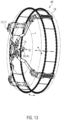
- FIG 13 is merely an example and only schematically indicated how an anti-skid device 75, shown here as an example as a self-fitting snow chain 77, can be attached to a vehicle rim 1 (only indicated as part of a vehicle tire 78) on a holding device 37 according to the invention.
- the holding device 37 has a holding section 45, which is shown here only as an example as part of a rod 39.
- a connecting part 79, for example a hook, of the anti-skid device 75 can be hooked onto this holding section 45.
Landscapes
- Engineering & Computer Science (AREA)
- Mechanical Engineering (AREA)
- Connection Of Plates (AREA)
- Regulating Braking Force (AREA)
- Tires In General (AREA)
Claims (13)
- Jante de véhicule (1) pour un véhicule automobile ou pour une remorque de véhicule automobile, dans laquelle la jante de véhicule (1) comporte un dispositif de fixation (3) pour fixer la jante de véhicule (1) à un moyeu de roue, dans laquelle le dispositif de fixation (3) comporte une pluralité d'ouvertures (5) pour le passage de boulons de roue, et dans laquelle la jante de véhicule (1) comporte, outre le dispositif de fixation (3), au moins un élément de connexion (15) qui est configuré pour connecter de manière amovible et répétée un dispositif de retenue (37) pour un dispositif antidérapant (75), dans laquelle ledit au moins un élément de connexion (15) est agencé à l'intérieur d'un cercle de boulonnage (9) formé par les ouvertures (5) ou d'une zone centrale (11) de la jante de véhicule (1) délimitée par le cercle de boulonnage (9),
caractérisée en ce que ledit au moins un élément de connexion (15) est formé de manière monolithique avec la jante de véhicule (1). - Jante de véhicule (1) selon la revendication 1, dans laquelle la jante de véhicule (1) comporte deux éléments de connexion (15) qui sont agencés face à face, de part et d'autre d'un alésage central (7) de la jante de véhicule (1) .
- Jante de véhicule (1) selon l'une des revendications 1 et 2, dans laquelle ledit au moins un élément de connexion (15) est conformé comme un alésage (17) dans la jante de véhicule (1).
- Jante de véhicule (1) selon l'une des revendications 1 à 3, dans laquelle ledit au moins un alésage (17) est pourvu d'un filetage interne (23).
- Jante de véhicule (1) selon l'une des revendications 1 à 4, dans laquelle ledit au moins un élément de connexion (15) est conformé comme une protubérance (67) qui ressort du reste de la jante de véhicule (1) sur un côté externe (13) de la jante de véhicule (1).
- Jante de véhicule (1) selon la revendication 5, dans laquelle la protubérance (67) présente au moins une ouverture de réception (33) qui s'étend dans la protubérance (67) transversalement à une direction axiale (A) de la jante de véhicule (1).
- Jante de véhicule (1) selon la revendication 5 ou 6, dans laquelle la protubérance (67) comporte au moins une rainure circonférentielle (69).
- Ensemble (48) comportant une jante de véhicule (1) selon l'une des revendications 1 à 7 et un dispositif de retenue (37) sur lequel peut être monté un dispositif antidérapant (75), dans lequel le dispositif de retenue (37) peut être monté de manière imperdable sur ledit au moins un élément de connexion (15).
- Ensemble (48) selon la revendication 8, dans lequel le dispositif de retenue (37), dans un état monté (47) sur la jante de véhicule (1), s'étend sur un côté externe (13) de la jante de véhicule (1) transversalement à un alésage central (7) de la jante de véhicule (1).
- Ensemble (48) selon la revendication 8 ou 9, dans lequel le dispositif de retenue (37) est constitué sous forme d'une barre (39) ou comporte une barre (39).
- Ensemble (48) selon l'une des revendications 8 à 10, dans lequel le dispositif de retenue (37) comporte au moins une pièce intermédiaire (25) amovible de manière répétée pour monter le dispositif de retenue (37) sur ledit au moins un élément de connexion (15).
- Ensemble (48) selon l'une des revendications 8 à 11, dans lequel le dispositif de retenue (37) comporte deux sections de fixation (43) qui se font face en direction longitudinale (56) du dispositif de retenue (37) et configurées chacune pour être fixées à un élément de connexion (15), et une section de retenue (45) agencée entre les deux sections de fixation (43) et conçue pour monter un dispositif antidérapant (75).
- Ensemble (48) selon l'une des revendications 8 à 12, comprenant en outre un dispositif antidérapant (75) configuré pour être monté sur le dispositif de retenue (37), en particulier une chaîne à neige à enroulement automatique (77).
Applications Claiming Priority (1)
| Application Number | Priority Date | Filing Date | Title |
|---|---|---|---|
| DE102021113878.7A DE102021113878A1 (de) | 2021-05-28 | 2021-05-28 | Fahrzeugfelge mit Anschlusselement für eine Haltevorrichtung zur Anbringung einer Gleitschutzvorrichtung |
Publications (3)
| Publication Number | Publication Date |
|---|---|
| EP4094953A1 EP4094953A1 (fr) | 2022-11-30 |
| EP4094953C0 EP4094953C0 (fr) | 2024-10-23 |
| EP4094953B1 true EP4094953B1 (fr) | 2024-10-23 |
Family
ID=81846643
Family Applications (1)
| Application Number | Title | Priority Date | Filing Date |
|---|---|---|---|
| EP22174991.4A Active EP4094953B1 (fr) | 2021-05-28 | 2022-05-24 | Jante de véhicule pourvue d'élément de liaison pour un dispositif de maintien destiné à l'application d'un dispositif antiglissement |
Country Status (2)
| Country | Link |
|---|---|
| EP (1) | EP4094953B1 (fr) |
| DE (1) | DE102021113878A1 (fr) |
Citations (2)
| Publication number | Priority date | Publication date | Assignee | Title |
|---|---|---|---|---|
| EP1160103A2 (fr) * | 2000-05-23 | 2001-12-05 | Anton Kahlbacher | Dispositif antidérapant pour roues avec pneumatiques |
| EP2206615A1 (fr) * | 2009-01-13 | 2010-07-14 | RuD Ketten Rieger & Dietz GmbH u. Co. KG | Dispositif de protection contre le glissement doté d'une liaison de jantes |
Family Cites Families (4)
| Publication number | Priority date | Publication date | Assignee | Title |
|---|---|---|---|---|
| DE3844494A1 (de) * | 1988-12-30 | 1990-07-05 | Rud Ketten Rieger & Dietz | Gleitschutzvorrichtung |
| DE19814017A1 (de) | 1998-03-28 | 1999-09-30 | Manfred Deichmann | Fahrzeugrad und Gleitschutz für solch ein Fahrzeugrad |
| DE102009004807A1 (de) | 2009-01-13 | 2010-07-15 | Rud Ketten Rieger & Dietz Gmbh &. Co. Kg | Gleitschutzvorrichtung für Fahrzeugräder mit ergonomischer Handhabe |
| CN105015286A (zh) * | 2014-04-30 | 2015-11-04 | 王锦林 | 便捷式轮胎防滑器 |
-
2021
- 2021-05-28 DE DE102021113878.7A patent/DE102021113878A1/de active Pending
-
2022
- 2022-05-24 EP EP22174991.4A patent/EP4094953B1/fr active Active
Patent Citations (2)
| Publication number | Priority date | Publication date | Assignee | Title |
|---|---|---|---|---|
| EP1160103A2 (fr) * | 2000-05-23 | 2001-12-05 | Anton Kahlbacher | Dispositif antidérapant pour roues avec pneumatiques |
| EP2206615A1 (fr) * | 2009-01-13 | 2010-07-14 | RuD Ketten Rieger & Dietz GmbH u. Co. KG | Dispositif de protection contre le glissement doté d'une liaison de jantes |
Also Published As
| Publication number | Publication date |
|---|---|
| EP4094953A1 (fr) | 2022-11-30 |
| EP4094953C0 (fr) | 2024-10-23 |
| DE102021113878A1 (de) | 2022-12-01 |
Similar Documents
| Publication | Publication Date | Title |
|---|---|---|
| DE69528688T2 (de) | Vorrichtung zum Verbinden von Teilen mit Lochungen von unterschiedlichem Achsabstand | |
| DE4205579C2 (de) | Zentralsicherungseinrichtung für Kraftfahrzeugräder | |
| DE19929966A1 (de) | Sicherungssystem für einen Bolzen und eine Mutter | |
| DE3317924A1 (de) | Fahrzeugradbefestigungseinrichtung | |
| DE19625318C2 (de) | Konusschraubverbindung für Lamellenpaket-Wellenkupplungen | |
| DE102022115126A1 (de) | Ein Verstellelement und ein Installationsverfahren für ein Anbauteil mithilfe des Verstellelements | |
| DE102007014479B4 (de) | Spannvorrichtung | |
| DE102007049767A1 (de) | Mehrteilige Felge | |
| EP4094953B1 (fr) | Jante de véhicule pourvue d'élément de liaison pour un dispositif de maintien destiné à l'application d'un dispositif antiglissement | |
| DE102013213514A1 (de) | Sicherungsvorrichtung zum Sichern einer Mutter gegen ungewolltes Losdrehen, sowie Lageranordnung einer Welle | |
| EP4052932B1 (fr) | Adaptateur d'accessoires destiné à la fixation des accessoires automobiles à un moyeu de roue à filetage central | |
| DE102018202660A1 (de) | Speichenrad für schlauchlose Reifen | |
| DE19631937A1 (de) | Ausgleichsgetriebe | |
| DE102009020123A1 (de) | Vorrichtung zum Verbinden einer Nabe und einer Felge an einem Laufrad | |
| EP0291709A2 (fr) | Goujon à dispositif de blocage pour roue de véhicule | |
| DE1296030B (de) | Zwillingsradanordnung bei mit luftbereiften Raedern ausgeruesteten Fahrzeugen und Fahrzeuganhaengern | |
| DE19836239C2 (de) | Fahrzeugrad | |
| EP1026419A2 (fr) | Moyeu de roue avec disque de frein pour frein à disque | |
| DE102007017700A1 (de) | Verliersicherung für eine Nutmutter bei einer Welle-Nabe-Verbindung | |
| DE4440240C1 (de) | Radbefestigung für Fahrzeuge | |
| EP4013670A1 (fr) | Suspension de roue pour une bicyclette | |
| EP1134440B1 (fr) | Ensemble de connexion | |
| DE10115534A1 (de) | Zentrale Felgenspanneinrichtung für Kraftfahrzeuge und betreffendes Befestigungsverfahren | |
| DE4100439C2 (de) | Kunststoff-Zierring für ein Kraftfahrzeugrad | |
| EP1862331B1 (fr) | Système de fixation de roues pour diverses unités de paliers de roues |
Legal Events
| Date | Code | Title | Description |
|---|---|---|---|
| PUAI | Public reference made under article 153(3) epc to a published international application that has entered the european phase |
Free format text: ORIGINAL CODE: 0009012 |
|
| STAA | Information on the status of an ep patent application or granted ep patent |
Free format text: STATUS: THE APPLICATION HAS BEEN PUBLISHED |
|
| AK | Designated contracting states |
Kind code of ref document: A1 Designated state(s): AL AT BE BG CH CY CZ DE DK EE ES FI FR GB GR HR HU IE IS IT LI LT LU LV MC MK MT NL NO PL PT RO RS SE SI SK SM TR |
|
| STAA | Information on the status of an ep patent application or granted ep patent |
Free format text: STATUS: REQUEST FOR EXAMINATION WAS MADE |
|
| 17P | Request for examination filed |
Effective date: 20230523 |
|
| RBV | Designated contracting states (corrected) |
Designated state(s): AL AT BE BG CH CY CZ DE DK EE ES FI FR GB GR HR HU IE IS IT LI LT LU LV MC MK MT NL NO PL PT RO RS SE SI SK SM TR |
|
| STAA | Information on the status of an ep patent application or granted ep patent |
Free format text: STATUS: EXAMINATION IS IN PROGRESS |
|
| 17Q | First examination report despatched |
Effective date: 20240111 |
|
| GRAP | Despatch of communication of intention to grant a patent |
Free format text: ORIGINAL CODE: EPIDOSNIGR1 |
|
| STAA | Information on the status of an ep patent application or granted ep patent |
Free format text: STATUS: GRANT OF PATENT IS INTENDED |
|
| INTG | Intention to grant announced |
Effective date: 20240610 |
|
| GRAS | Grant fee paid |
Free format text: ORIGINAL CODE: EPIDOSNIGR3 |
|
| GRAA | (expected) grant |
Free format text: ORIGINAL CODE: 0009210 |
|
| STAA | Information on the status of an ep patent application or granted ep patent |
Free format text: STATUS: THE PATENT HAS BEEN GRANTED |
|
| AK | Designated contracting states |
Kind code of ref document: B1 Designated state(s): AL AT BE BG CH CY CZ DE DK EE ES FI FR GB GR HR HU IE IS IT LI LT LU LV MC MK MT NL NO PL PT RO RS SE SI SK SM TR |
|
| REG | Reference to a national code |
Ref country code: GB Ref legal event code: FG4D Free format text: NOT ENGLISH |
|
| REG | Reference to a national code |
Ref country code: CH Ref legal event code: EP |
|
| REG | Reference to a national code |
Ref country code: DE Ref legal event code: R096 Ref document number: 502022001944 Country of ref document: DE |
|
| REG | Reference to a national code |
Ref country code: IE Ref legal event code: FG4D Free format text: LANGUAGE OF EP DOCUMENT: GERMAN |
|
| U01 | Request for unitary effect filed |
Effective date: 20241118 |
|
| U07 | Unitary effect registered |
Designated state(s): AT BE BG DE DK EE FI FR IT LT LU LV MT NL PT RO SE SI Effective date: 20241122 |
|
| PG25 | Lapsed in a contracting state [announced via postgrant information from national office to epo] |
Ref country code: HR Free format text: LAPSE BECAUSE OF FAILURE TO SUBMIT A TRANSLATION OF THE DESCRIPTION OR TO PAY THE FEE WITHIN THE PRESCRIBED TIME-LIMIT Effective date: 20241023 Ref country code: IS Free format text: LAPSE BECAUSE OF FAILURE TO SUBMIT A TRANSLATION OF THE DESCRIPTION OR TO PAY THE FEE WITHIN THE PRESCRIBED TIME-LIMIT Effective date: 20250223 |
|
| PG25 | Lapsed in a contracting state [announced via postgrant information from national office to epo] |
Ref country code: ES Free format text: LAPSE BECAUSE OF FAILURE TO SUBMIT A TRANSLATION OF THE DESCRIPTION OR TO PAY THE FEE WITHIN THE PRESCRIBED TIME-LIMIT Effective date: 20241023 |
|
| PG25 | Lapsed in a contracting state [announced via postgrant information from national office to epo] |
Ref country code: NO Free format text: LAPSE BECAUSE OF FAILURE TO SUBMIT A TRANSLATION OF THE DESCRIPTION OR TO PAY THE FEE WITHIN THE PRESCRIBED TIME-LIMIT Effective date: 20250123 |
|
| PG25 | Lapsed in a contracting state [announced via postgrant information from national office to epo] |
Ref country code: GR Free format text: LAPSE BECAUSE OF FAILURE TO SUBMIT A TRANSLATION OF THE DESCRIPTION OR TO PAY THE FEE WITHIN THE PRESCRIBED TIME-LIMIT Effective date: 20250124 |
|
| PG25 | Lapsed in a contracting state [announced via postgrant information from national office to epo] |
Ref country code: PL Free format text: LAPSE BECAUSE OF FAILURE TO SUBMIT A TRANSLATION OF THE DESCRIPTION OR TO PAY THE FEE WITHIN THE PRESCRIBED TIME-LIMIT Effective date: 20241023 |
|
| PG25 | Lapsed in a contracting state [announced via postgrant information from national office to epo] |
Ref country code: RS Free format text: LAPSE BECAUSE OF FAILURE TO SUBMIT A TRANSLATION OF THE DESCRIPTION OR TO PAY THE FEE WITHIN THE PRESCRIBED TIME-LIMIT Effective date: 20250123 |
|
| U20 | Renewal fee for the european patent with unitary effect paid |
Year of fee payment: 4 Effective date: 20250528 |
|
| PG25 | Lapsed in a contracting state [announced via postgrant information from national office to epo] |
Ref country code: SM Free format text: LAPSE BECAUSE OF FAILURE TO SUBMIT A TRANSLATION OF THE DESCRIPTION OR TO PAY THE FEE WITHIN THE PRESCRIBED TIME-LIMIT Effective date: 20241023 |
|
| PG25 | Lapsed in a contracting state [announced via postgrant information from national office to epo] |
Ref country code: SK Free format text: LAPSE BECAUSE OF FAILURE TO SUBMIT A TRANSLATION OF THE DESCRIPTION OR TO PAY THE FEE WITHIN THE PRESCRIBED TIME-LIMIT Effective date: 20241023 |
|
| PG25 | Lapsed in a contracting state [announced via postgrant information from national office to epo] |
Ref country code: CZ Free format text: LAPSE BECAUSE OF FAILURE TO SUBMIT A TRANSLATION OF THE DESCRIPTION OR TO PAY THE FEE WITHIN THE PRESCRIBED TIME-LIMIT Effective date: 20241023 |
|
| PLBE | No opposition filed within time limit |
Free format text: ORIGINAL CODE: 0009261 |
|
| STAA | Information on the status of an ep patent application or granted ep patent |
Free format text: STATUS: NO OPPOSITION FILED WITHIN TIME LIMIT |
|
| 26N | No opposition filed |
Effective date: 20250724 |
|
| REG | Reference to a national code |
Ref country code: CH Ref legal event code: H13 Free format text: ST27 STATUS EVENT CODE: U-0-0-H10-H13 (AS PROVIDED BY THE NATIONAL OFFICE) Effective date: 20251223 |
|
| PG25 | Lapsed in a contracting state [announced via postgrant information from national office to epo] |
Ref country code: CH Free format text: LAPSE BECAUSE OF NON-PAYMENT OF DUE FEES Effective date: 20250531 |
|
| PG25 | Lapsed in a contracting state [announced via postgrant information from national office to epo] |
Ref country code: MC Free format text: LAPSE BECAUSE OF FAILURE TO SUBMIT A TRANSLATION OF THE DESCRIPTION OR TO PAY THE FEE WITHIN THE PRESCRIBED TIME-LIMIT Effective date: 20241023 |
|
| PG25 | Lapsed in a contracting state [announced via postgrant information from national office to epo] |
Ref country code: IE Free format text: LAPSE BECAUSE OF NON-PAYMENT OF DUE FEES Effective date: 20250524 |