EP4094964B1 - Camion électrique - Google Patents
Camion électrique Download PDFInfo
- Publication number
- EP4094964B1 EP4094964B1 EP20916288.2A EP20916288A EP4094964B1 EP 4094964 B1 EP4094964 B1 EP 4094964B1 EP 20916288 A EP20916288 A EP 20916288A EP 4094964 B1 EP4094964 B1 EP 4094964B1
- Authority
- EP
- European Patent Office
- Prior art keywords
- double
- tire
- outer tube
- steering
- truck
- Prior art date
- Legal status (The legal status is an assumption and is not a legal conclusion. Google has not performed a legal analysis and makes no representation as to the accuracy of the status listed.)
- Active
Links
Images




Classifications
-
- B—PERFORMING OPERATIONS; TRANSPORTING
- B62—LAND VEHICLES FOR TRAVELLING OTHERWISE THAN ON RAILS
- B62D—MOTOR VEHICLES; TRAILERS
- B62D7/00—Steering linkage; Stub axles or their mountings
- B62D7/02—Steering linkage; Stub axles or their mountings for pivoted bogies
- B62D7/04—Steering linkage; Stub axles or their mountings for pivoted bogies with more than one wheel
-
- B—PERFORMING OPERATIONS; TRANSPORTING
- B60—VEHICLES IN GENERAL
- B60G—VEHICLE SUSPENSION ARRANGEMENTS
- B60G11/00—Resilient suspensions characterised by arrangement, location or kind of springs
- B60G11/26—Resilient suspensions characterised by arrangement, location or kind of springs having fluid springs only, e.g. hydropneumatic springs
- B60G11/27—Resilient suspensions characterised by arrangement, location or kind of springs having fluid springs only, e.g. hydropneumatic springs wherein the fluid is a gas
-
- B—PERFORMING OPERATIONS; TRANSPORTING
- B60—VEHICLES IN GENERAL
- B60G—VEHICLE SUSPENSION ARRANGEMENTS
- B60G11/00—Resilient suspensions characterised by arrangement, location or kind of springs
- B60G11/26—Resilient suspensions characterised by arrangement, location or kind of springs having fluid springs only, e.g. hydropneumatic springs
- B60G11/28—Resilient suspensions characterised by arrangement, location or kind of springs having fluid springs only, e.g. hydropneumatic springs characterised by means specially adapted for attaching the spring to axle or sprung part of the vehicle
-
- B—PERFORMING OPERATIONS; TRANSPORTING
- B60—VEHICLES IN GENERAL
- B60G—VEHICLE SUSPENSION ARRANGEMENTS
- B60G11/00—Resilient suspensions characterised by arrangement, location or kind of springs
- B60G11/32—Resilient suspensions characterised by arrangement, location or kind of springs having springs of different kinds
- B60G11/48—Resilient suspensions characterised by arrangement, location or kind of springs having springs of different kinds not including leaf springs
- B60G11/56—Resilient suspensions characterised by arrangement, location or kind of springs having springs of different kinds not including leaf springs having helical, spiral or coil springs, and also fluid springs
-
- B—PERFORMING OPERATIONS; TRANSPORTING
- B60—VEHICLES IN GENERAL
- B60G—VEHICLE SUSPENSION ARRANGEMENTS
- B60G11/00—Resilient suspensions characterised by arrangement, location or kind of springs
- B60G11/32—Resilient suspensions characterised by arrangement, location or kind of springs having springs of different kinds
- B60G11/48—Resilient suspensions characterised by arrangement, location or kind of springs having springs of different kinds not including leaf springs
- B60G11/56—Resilient suspensions characterised by arrangement, location or kind of springs having springs of different kinds not including leaf springs having helical, spiral or coil springs, and also fluid springs
- B60G11/58—Resilient suspensions characterised by arrangement, location or kind of springs having springs of different kinds not including leaf springs having helical, spiral or coil springs, and also fluid springs arranged coaxially
-
- B—PERFORMING OPERATIONS; TRANSPORTING
- B60—VEHICLES IN GENERAL
- B60K—ARRANGEMENT OR MOUNTING OF PROPULSION UNITS OR OF TRANSMISSIONS IN VEHICLES; ARRANGEMENT OR MOUNTING OF PLURAL DIVERSE PRIME-MOVERS IN VEHICLES; AUXILIARY DRIVES FOR VEHICLES; INSTRUMENTATION OR DASHBOARDS FOR VEHICLES; ARRANGEMENTS IN CONNECTION WITH COOLING, AIR INTAKE, GAS EXHAUST OR FUEL SUPPLY OF PROPULSION UNITS IN VEHICLES
- B60K1/00—Arrangement or mounting of electrical propulsion units
-
- B—PERFORMING OPERATIONS; TRANSPORTING
- B60—VEHICLES IN GENERAL
- B60K—ARRANGEMENT OR MOUNTING OF PROPULSION UNITS OR OF TRANSMISSIONS IN VEHICLES; ARRANGEMENT OR MOUNTING OF PLURAL DIVERSE PRIME-MOVERS IN VEHICLES; AUXILIARY DRIVES FOR VEHICLES; INSTRUMENTATION OR DASHBOARDS FOR VEHICLES; ARRANGEMENTS IN CONNECTION WITH COOLING, AIR INTAKE, GAS EXHAUST OR FUEL SUPPLY OF PROPULSION UNITS IN VEHICLES
- B60K7/00—Disposition of motor in, or adjacent to, traction wheel
- B60K7/0007—Disposition of motor in, or adjacent to, traction wheel the motor being electric
-
- B—PERFORMING OPERATIONS; TRANSPORTING
- B62—LAND VEHICLES FOR TRAVELLING OTHERWISE THAN ON RAILS
- B62D—MOTOR VEHICLES; TRAILERS
- B62D7/00—Steering linkage; Stub axles or their mountings
- B62D7/06—Steering linkage; Stub axles or their mountings for individually-pivoted wheels, e.g. on king-pins
- B62D7/14—Steering linkage; Stub axles or their mountings for individually-pivoted wheels, e.g. on king-pins the pivotal axes being situated in more than one plane transverse to the longitudinal centre line of the vehicle, e.g. all-wheel steering
- B62D7/15—Steering linkage; Stub axles or their mountings for individually-pivoted wheels, e.g. on king-pins the pivotal axes being situated in more than one plane transverse to the longitudinal centre line of the vehicle, e.g. all-wheel steering characterised by means varying the ratio between the steering angles of the steered wheels
- B62D7/1509—Steering linkage; Stub axles or their mountings for individually-pivoted wheels, e.g. on king-pins the pivotal axes being situated in more than one plane transverse to the longitudinal centre line of the vehicle, e.g. all-wheel steering characterised by means varying the ratio between the steering angles of the steered wheels with different steering modes, e.g. crab-steering, or steering specially adapted for reversing of the vehicle
-
- B—PERFORMING OPERATIONS; TRANSPORTING
- B60—VEHICLES IN GENERAL
- B60G—VEHICLE SUSPENSION ARRANGEMENTS
- B60G2200/00—Indexing codes relating to suspension types
- B60G2200/40—Indexing codes relating to the wheels in the suspensions
- B60G2200/422—Driving wheels or live axles
-
- B—PERFORMING OPERATIONS; TRANSPORTING
- B60—VEHICLES IN GENERAL
- B60G—VEHICLE SUSPENSION ARRANGEMENTS
- B60G2200/00—Indexing codes relating to suspension types
- B60G2200/40—Indexing codes relating to the wheels in the suspensions
- B60G2200/44—Indexing codes relating to the wheels in the suspensions steerable
-
- B—PERFORMING OPERATIONS; TRANSPORTING
- B60—VEHICLES IN GENERAL
- B60G—VEHICLE SUSPENSION ARRANGEMENTS
- B60G2202/00—Indexing codes relating to the type of spring, damper or actuator
- B60G2202/10—Type of spring
- B60G2202/15—Fluid spring
- B60G2202/152—Pneumatic spring
-
- B—PERFORMING OPERATIONS; TRANSPORTING
- B60—VEHICLES IN GENERAL
- B60G—VEHICLE SUSPENSION ARRANGEMENTS
- B60G2204/00—Indexing codes related to suspensions per se or to auxiliary parts
- B60G2204/10—Mounting of suspension elements
- B60G2204/12—Mounting of springs or dampers
- B60G2204/124—Mounting of coil springs
-
- B—PERFORMING OPERATIONS; TRANSPORTING
- B60—VEHICLES IN GENERAL
- B60G—VEHICLE SUSPENSION ARRANGEMENTS
- B60G2204/00—Indexing codes related to suspensions per se or to auxiliary parts
- B60G2204/10—Mounting of suspension elements
- B60G2204/12—Mounting of springs or dampers
- B60G2204/126—Mounting of pneumatic springs
-
- B—PERFORMING OPERATIONS; TRANSPORTING
- B60—VEHICLES IN GENERAL
- B60G—VEHICLE SUSPENSION ARRANGEMENTS
- B60G2300/00—Indexing codes relating to the type of vehicle
- B60G2300/02—Trucks; Load vehicles
- B60G2300/026—Heavy duty trucks
- B60G2300/0262—Multi-axle trucks
-
- B—PERFORMING OPERATIONS; TRANSPORTING
- B60—VEHICLES IN GENERAL
- B60G—VEHICLE SUSPENSION ARRANGEMENTS
- B60G2300/00—Indexing codes relating to the type of vehicle
- B60G2300/37—Vehicles having steerable wheels mounted on a vertically moving column
-
- B—PERFORMING OPERATIONS; TRANSPORTING
- B60—VEHICLES IN GENERAL
- B60G—VEHICLE SUSPENSION ARRANGEMENTS
- B60G2300/00—Indexing codes relating to the type of vehicle
- B60G2300/50—Electric vehicles; Hybrid vehicles
-
- B—PERFORMING OPERATIONS; TRANSPORTING
- B60—VEHICLES IN GENERAL
- B60K—ARRANGEMENT OR MOUNTING OF PROPULSION UNITS OR OF TRANSMISSIONS IN VEHICLES; ARRANGEMENT OR MOUNTING OF PLURAL DIVERSE PRIME-MOVERS IN VEHICLES; AUXILIARY DRIVES FOR VEHICLES; INSTRUMENTATION OR DASHBOARDS FOR VEHICLES; ARRANGEMENTS IN CONNECTION WITH COOLING, AIR INTAKE, GAS EXHAUST OR FUEL SUPPLY OF PROPULSION UNITS IN VEHICLES
- B60K1/00—Arrangement or mounting of electrical propulsion units
- B60K2001/001—Arrangement or mounting of electrical propulsion units one motor mounted on a propulsion axle for rotating right and left wheels of this axle
-
- B—PERFORMING OPERATIONS; TRANSPORTING
- B60—VEHICLES IN GENERAL
- B60K—ARRANGEMENT OR MOUNTING OF PROPULSION UNITS OR OF TRANSMISSIONS IN VEHICLES; ARRANGEMENT OR MOUNTING OF PLURAL DIVERSE PRIME-MOVERS IN VEHICLES; AUXILIARY DRIVES FOR VEHICLES; INSTRUMENTATION OR DASHBOARDS FOR VEHICLES; ARRANGEMENTS IN CONNECTION WITH COOLING, AIR INTAKE, GAS EXHAUST OR FUEL SUPPLY OF PROPULSION UNITS IN VEHICLES
- B60K7/00—Disposition of motor in, or adjacent to, traction wheel
- B60K2007/0038—Disposition of motor in, or adjacent to, traction wheel the motor moving together with the wheel axle
-
- B—PERFORMING OPERATIONS; TRANSPORTING
- B60—VEHICLES IN GENERAL
- B60K—ARRANGEMENT OR MOUNTING OF PROPULSION UNITS OR OF TRANSMISSIONS IN VEHICLES; ARRANGEMENT OR MOUNTING OF PLURAL DIVERSE PRIME-MOVERS IN VEHICLES; AUXILIARY DRIVES FOR VEHICLES; INSTRUMENTATION OR DASHBOARDS FOR VEHICLES; ARRANGEMENTS IN CONNECTION WITH COOLING, AIR INTAKE, GAS EXHAUST OR FUEL SUPPLY OF PROPULSION UNITS IN VEHICLES
- B60K7/00—Disposition of motor in, or adjacent to, traction wheel
- B60K2007/0061—Disposition of motor in, or adjacent to, traction wheel the motor axle being parallel to the wheel axle
Definitions
- the present disclosure relates to an electric truck according to claim 1.
- CN 107 989 945 A provides an oil-gas spring, a wheel steering mechanism provided with the oil-gas spring, a wheel provided with the oil-gas spring and a vehicle adopting the wheel.
- US 3 049 361 A discloses a wheel suspension for a tractor and semi-trailer type vehicle with linked frames, comprising for each side of each frame a pair of generally forwardly and rearwardly extending tandem members operatively attached to the associated frame.
- WO 01/53141 A1 discloses a truck having a frame with a forward end and a rearward end. The rearward end of the frame is supported by at least two wheels coupled to part of the frame. The truck also has a forward strut support coupled to the frame near the forward end.
- the truck has at least first and second struct modules coupled to the forward strut support.
- the first and second strut modules each have an independent steering mechanism and at least one wheel and tire assembly.
- Each of the first and second strut modules can also have one or more motors for driving a respective wheel and tire assembly independent of each other wheel and tire assembly of that strut module and of the other strut module.
- CN 110 371 216 A provides a steering running mechanism used for an AGV and a control method.
- an object of the present disclosure to provide an electric truck comprising a drive device having a steering performance of a steering angle of 0° to 180° while satisfying a desired suspension performance.
- the drive shaft of the double-tire is extended in a vehicle width direction with the truck traveling straight forward; and the final gear is positioned at a center of two wheels constituting the double-tire in the vehicle width direction and distributes the drive power amplified by the reducer to the two wheels and the drive device further comprises a suspension part and a steering gear part provided above and integrated with the suspension part and configured to steer the double-tire, whereby the suspension part and the steering gear part are integrally integrated above the final gear.
- This drive device drives each individual double-tire and steers each individual double-tire, and consequently can achieve a steering angle in the range of 0° to 180°, which makes the turning radius small. Accordingly, it is possible to provide a drive device for a truck having a steering performance of 0° to 180° in steering angle while satisfying a desired suspension performance.
- suspension part and the steering gear part are not integrated and only the steering gear part is provided above the drive unit, it is necessary to install a large suspension part for a commercial vehicle such as a leaf spring in the vicinity of the drive unit in order to provide sufficient suspension performance as an electric truck.
- the drive device is provided with the steering gear part, the steering performance is limited by the suspension part, and as a result, it is difficult to provide the drive device for the electric truck having the steering performance of the steering angle of 0° to 180°.
- the suspension part and the steering gear part may be disposed over a space between two wheels constituting the double-tire.
- the suspension part and the steering gear part are disposed over a space between two wheels constituting the double-tire, so that the steering performance of the double-tire can be enhanced.
- the suspension part may be an air suspension including: an outer tube centered at a steering shaft of the double-tire; and an inner tube being concentric with the outer tube, being slidable along an inner circumference face of the outer tube in an axis direction, and being incapable of relatively rotating with respect to the outer tube.
- the configuration is simplified as compared with a hydraulic suspension or an electromagnetic suspension.
- the suspension part may further include a coil spring surrounding the outer tube and the inner tube.
- the suspension part includes a coil spring surrounding the outer tube and the inner tube, it possible to provide a suspension part suitable for the overall weight of the vehicle.
- the suspension part may further include a low frictional member being arranged at a point where the outer tube is brought into slidable contact with the inner tube and reducing sliding friction of the outer tube with the inner tube.
- the suspension part includes a low frictional member being arranged at a point where the outer tube is brought into slidable contact with the inner tube and reducing sliding friction of the outer tube with the inner tube, the friction at the suspension part is reduced.
- the steering gear part may be configured to be capable of steering the double-tire up to 90° leftward and rightward on an assumption that a steering angle of the double-tire when the drive shaft extends in a vehicle width direction is 0°.
- the steering gear part is configured to be capable of steering the double-tire up to 90° leftward and rightward on an assumption that a steering angle of the double-tire when the drive shaft extends in a vehicle width direction is 0°, the steering performance can be enhanced and mobile parking in the left-right direction is also possible, for example.
- the final gear of each of the drive units may be included in a differential gear.
- a drive device for an electric truck having a steering performance of a steering angle of 0° to 180° while satisfying a desired suspension performance.
- a drive device for an electric truck according to an embodiment will now be described with reference to accompanying drawings.
- the following embodiment is merely example, so there is no intention to exclude various modifications and applications of techniques not explicitly described in the following embodiment.
- Each of the structures of the present embodiment can be variously modified without departing from the scope of the structure.
- the structures may be appropriately selected, omitted, or combined according to the requirement.
- the drive device is applied to an electric truck 1 that travels only by drive power of a motor 11 (see FIG. 3 ) without an internal combustion engine.
- the electric truck 1 (hereinafter simply referred to as the "truck 1") including a pair of left and right side frames 1A (also referred to as chassis frames) extending in the front-rear direction of the vehicle and a cab 1B disposed in the front part of the vehicle is illustrated, and the illustration of the body is omitted.
- a frame extending in the vehicle widthwise direction may be provided, or the side frames 1A may be omitted.
- the forward direction of the truck 1 will be referred to as the "front”, and the opposite direction to the front will be referred to as the "rear”.
- the left-right direction is determined with reference to the state of the truck 1 facing forward.
- the left-right direction is orthogonal to the front-rear direction of the vehicle.
- the left-right direction is referred to as a "vehicle width direction”
- the front-rear direction of the vehicle is simply referred to as a "front-rear direction”.
- the truck 1 includes double-tires 2 each consisting of two wheels 2A (drive wheels).
- double-tires 2 each consisting of two wheels 2A (drive wheels).
- a pair of left and right double-tires 2 are provided on the front side (front wheel side) of the vehicle, and two pairs of left and right double-tires 2 are provided side by side on the rear side (rear wheel side) of the vehicle, but the number of double-tires 2 in the front-rear direction is not limited to this.
- Each double-tire 2 is provided with one drive unit 10 including the motor 11, and the drive power of the motor 11 is transmitted to the double-tire 2. The configuration of the drive unit 10 will be described later.
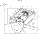
- the truck 1 of the present embodiment includes a body frame casing 5 composed of a pair of mounting frame bodies 5A extending in the vehicle width direction, a pair of cross members 5B and a pair of cross members 5C connecting the mounting frame bodies 5A, and body-connecting parts 32 and 33 for connecting the drive unit 10 disposed in the frame of the body frame casing 5 to the respective mounting frame bodies 5A.
- the pair of mounting frame bodies 5A are disposed apart from each other in the front-rear direction.
- Each of the cross members 5B and 5C connects the front and rear mounting frame bodies 5A.
- the pair of left and right drive units 10 are disposed in the frame of the body frame casing 5 so as to be adjacent to each other in the vehicle width direction.
- one body frame casing 5 is provided on the front side (front wheel side) of the vehicle, and two body frame casings 5 are provided on the rear side (rear wheel side) of the vehicle, but the number of body frame casings 5 in front and that in rear are not limited to these.
- the body frame casing 5 in which the pair of left and right drive units 10 are connected by the body-connecting parts 32 and 33 constitutes a front axle and a rear axle of the vehicle.
- the body frame casing 5 of the present embodiment is formed of a rectangular flat plate member in which the front and rear mounting frame bodies 5A extend in the vehicle width direction and the vertical direction.
- the cross members 5B located above the body frame casing 5 are each formed of a member having a U-shaped or hat-shaped cross section extending in the front-rear direction, and connects the flanges at the upper ends of the front and rear mounting frame bodies 5A.
- the cross members 5C located on the sides of the body frame casing 5 are each formed of a flat plate member extending in the front-rear direction and the vertical direction and having a concave portion formed so as to surround the wheel 2A. Any one of the cross members 5B and 5C may be omitted.
- the front body-connecting part 32 connects the front side of the drive unit 10 in the frame to the front mounting frame body 5A
- the rear body-connecting part 33 connects the rear side of the drive unit 10 in the frame to the rear mounting frame body 5A.
- the front and rear body-connecting parts 32 and 33 are formed in the same manner (front and rear symmetric). Each of the body-connecting parts 32 and 33 extends in the front-rear direction and is connected to the mounting frame body 5A to constitute a part of the frame of the truck 1.
- a planar mounting face 32a extending in a direction orthogonal to the front-rear direction is provided.
- a pair of connecting side protruding portions 32b protruding rearward is provided.
- the mounting face 32a is a part to be attached to the mounting frame body 5A, and has a fastening hole (not shown).
- the pair of connecting side protruding portions 32b are separated from each other in the vehicle width direction, and have holes 32c penetrating in the vehicle width direction.
- the connecting side protruding portion 32b constitutes a part of a hinge part 40, which will be described below, and is connected to a steering gear part 30, which will also be described below.
- a planar mounting face 33a extending in a direction orthogonal to the front-rear direction is provided.
- a pair of connecting side protruding portions 33b protruding forward and each having a hole 33c are provided.
- the configuration of the mounting face 33a and the connecting side protruding portions 33b are the same as the configuration of the mounting face 32a and the connecting side protruding portions 32b, respectively.
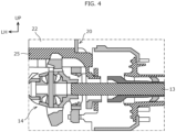
- the drive unit 10 includes the motor 11 that generates drive power, a reducer 12 that reduces a rotation speed of the motor 11, a final gear 14 that is connected to the reducer 12 and transfers the drive power of the motor 11 to a drive shaft 13 of the double-tire 2, and a drive unit housing 15 that integrally accommodates these units. That is, the drive unit housing 15 integrally houses the motor 11, the reducer 12, and the final gear 14.
- the motor 11 functions as an electric motor when the vehicle is driven, and functions as an electric generator when the vehicle is decelerated.
- the reducer 12 decelerates the rotation speed of the motor 11 to amplify the motor torque (drive power).
- the drive shaft 13 is extended in the vehicle width direction with the truck 1 traveling straight forward, and is arranged in pairs on the left and right across the final gear 14.
- the final gear 14 is positioned substantially at the center of the two wheels 2A in the vehicle width direction, and distributes the drive power of the motor 11 amplified by the reducer 12 to the two wheels 2A.
- the final gear 14 may be included in a differential gear. However, in the double-tire 2, the differential gear can be omitted because the two wheels 2A are closer to each other than the normal left and right wheels.
- the drive device of the truck 1 includes a suspension part 20 integrally integrated with above the final gear 14 in the drive unit housing 15, and a steering gear part 30 integrally integrated with above the suspension part 20. Further, the drive device of the present embodiment includes the pair of hinge parts 40 provided one on each of the vehicle front side and the vehicle rear side of the steering gear part 30, respectively, and the body-connecting parts 32 and 33 described above.
- the suspension part 20 functions as a suspension for absorbing vertical vibration of the double-tire 2.
- the steering gear part 30 is configured to be able to steer the double-tire 2, and has a function of steering the double-tire 2 around a steering shaft 30a (changing a steering angle).
- the double-tire 2 may be steered manually or automatically.
- Each double-tire 2 is individually driven and individually steered.
- the hinge part 40 has a function of suppressing the vertical vibration of the double-tire 2 from being transmitted to the vehicle body.
- the body-connecting parts 32 and 33 are for connecting the steering gear part 30 and the vehicle body of the truck 1 through the pair of hinge parts 40. A pair of the front and rear body-connecting parts 32 and 33 are provided across the steering shaft 30a.
- both the suspension part 20 and the steering gear part 30 are located above a space between the two wheels 2A constituting the double-tire 2.
- the motor 11 is disposed in front of the final gear 14 and above the reducer 12, but the position of the motor 11 may be set according to the specification and the size of the motor 11, the space in which the motor 11 can be disposed, and the like.
- the motor 11 may be disposed behind the final gear 14, or may be disposed obliquely above the final gear 14.
- the output shaft (not shown) of the motor 11 may be disposed in a downward extending posture.
- the suspension part 20 of the present embodiment is an air suspension including an outer tube 21 centered at the steering shaft 30a of the double-tire 2, and an inner tube 22 being concentric with the outer tube 21.
- the inner tube 22 is slidable along an inner circumference face of the outer tube 21 in an axis direction and incapable of relatively rotating with respect to the outer tube 21.
- the steering shaft 30a is a shaft portion having a steering center Cs when the double-tire 2 is steered, and extends in the vertical direction.
- the steering center Cs coincides with the centers of the outer tube 21 and the inner tube 22.
- the suspension part 20 may also have a coil spring 28 surrounding the outer tube 21 and the inner tube 22.
- the suspension part 20 having the coil spring 28 is applied to the relatively lightweight truck 1.
- the suspension part 20 without the coil spring 28 shown in Fig. 5 and Fig. 6 is applied to the truck 1 which has a relatively large weight because the suspension part 20 has a larger capacity of air than that of the suspension part 20 having the coil spring 28.
- the suspension part 20 shown in Fig. 7 is basically the same as the suspension part 20 shown in Fig. 5 and Fig. 6 except that the coil spring 28 is provided. Therefore, hereinafter, Fig. 7 will be described with reference to one of the embodiments.
- Fig. 7 schematically shows the drive unit 10.
- each of the outer tube 21 and the inner tube 22 has a vertically-long cylindrical shape, and the inner diameter of the outer tube 21 is slightly larger than the outer diameter of the inner tube 22.
- the upper opening of the outer tube 21 is sealed by a cover part 30b to which the steering shaft 30a is fixed, and the lower opening of the outer tube 21 communicates with the inner tube 22 by insertion of the upper portion of the inner tube 22.
- the upper opening of the inner tube 22 enters the lower portion of the outer tube 21 and communicates with the outer tube 21, the lower opening of the inner tube 22 is sealed with a flat drive head 25. Air is sealed inside the outer tube 21 and the inner tube 22.
- the drive head 25 may have a stepped shape so that the drive head 25 is also fixed to the inner circumference face at the lower end of the inner tube 22. In this case, the fixation between the inner tube 22 and the drive head 25 becomes strong, and it becomes possible to resist a load in the lateral direction.
- a stopper 24 that prevents the inner tube 22 from coming off and that seals the lower end of the outer tube 21 is fixed to the lower end of the outer tube 21.
- the suspension part 20 of the present embodiment includes a low frictional member 23 being arranged at a point where the outer tube 21 is brought into slidable contact with the inner tube 22.
- the low frictional member 23 is a member that reduces sliding friction of the outer tube 21 with inner tube 22, and is attached to, for example, the inner circumference face of the outer tube 21 or the outer circumference face of the inner tube 22. The low frictional member 23 avoids direct contact between the outer tube 21 and the inner tube 22, and reduces the friction when these slide relatively in the vertical direction.
- an annular attaching part 26 is fixed to the outer circumference face of the upper portion of the outer tube 21, and the attaching part 26 and the drive head 25 are linked by a stabilizer 27 (also referred to as a steering arm).
- a stabilizer 27 also referred to as a steering arm.
- shock absorbers 29 are provided on both left and right sides of the stabilizer 27, respectively.
- the shock absorber 29 has an upper end connected to the attaching part 26 and a lower end connected to the drive head 25 via mounting components.
- the steering gear part 30 of the present embodiment is configured to be capable of steering the double-tire 2 up to 90° leftward and rightward on an assumption that a steering angle of the double-tire 2 under a state where the truck 1 is traveling straight forward (that is, when the drive shaft 13 extends in the vehicle width direction) is 0° (reference). That is, the double-tire 2 can be steered by 180° by the steering gear part 30, and when the double-tire 2 is steered 90° leftward or rightward from the forward direction, the extending direction of the drive shaft 13 becomes the front-rear direction, and the truck 1 can move in the left-right direction.
- the steering gear part 30 includes the steering shaft 30a fixed to the cover part 30b, a spur gear 30c fixed to the steering shaft 30a, an annular gear 30d that meshes with the spur gear 30c, a tube portion 30e concentrically arranged with the steering shaft 30a, and a driving part 31 connected to the annular gear 30d to rotate the annular gear 30d.
- the driving part 31 is an actuator such as a hydraulic cylinder or a stepping motor.
- the steering shaft 30a when the driving part 31 rotates the annular gear 30d clockwise in a top view, the spur gear 30c also rotates clockwise. Accordingly, since the steering shaft 30a also rotates clockwise, the double-tire 2 is steered rightward. Conversely, when the driving part 31 rotates the annular gear 30d counterclockwise, the spur gear 30c also rotates counterclockwise. Accordingly, since the steering shaft 30a also rotates counterclockwise, the double-tire 2 is steered leftward. As illustrated in Fig. 3 , the steering shaft 30a is disposed equidistant from each of the pair of mounting frame bodies 5A.
- a pair of front and rear protruding portions 30f are formed on the tube portion 30e and connected to the connecting side protruding portions 32b and 33b of the body-connecting parts 32 and 33, respectively.
- the protruding portion 30f protrudes in the front-rear direction from each of the outer circumference face on the front side and the outer circumference face on the rear side of the tube portion 30e, and forms the hinge part 40 together with the above-mentioned connecting side protruding portions 32b and 33b.
- the front protruding portion 30f is interposed between the pair of connecting side protruding portions 32b, and a portion functioning as a rotating center Ch of the hinge parts 40 is inserted into the hole 32c of each connecting side protruding portion 32b.
- a cylindrical portion (not shown) having a through hole 30g penetrating in the vehicle width direction is inserted into the hole 32c.
- the rear protruding portion 30f is interposed between the pair of connecting side protruding portions 33b, and a cylindrical portion functioning as the rotating center Ch of the hinge part 40 is inserted into the hole 33c of each connecting side protruding portion 33b.
- a bush (not shown) that absorbs a load to be transmitted to the vehicle body is interposed in the hinge parts 40 of the present embodiment. With the bush interposed, the load to be transmitted to the vehicle body is absorbed, and the drive feel is further improved.
- the cover part 30b and the upper portion of the outer tube 21 are concentrically arranged and rotatably supported with respect to the tube portion 30e. That is, the outer tube 21, the inner tube 22, the cover part 30b, and the drive head 25 rotate integrally about the steering shaft 30a with respect to the tube portion 30e.
- a thrust plate 34 that receives a vertical load is interposed between the inner circumference face of the tube portion 30e and the outer circumference face of the outer tube 21.
- a stopper 36 for preventing the outer tube 21 from coming off is fixed.
- the thrust plate 34 of the present embodiment includes a cylinder portion 34a located between the tube portion 30e and the outer tube 21, and a flange portion 34b projecting radially outward from a lower end of the cylinder portion 34a.
- the flange portion 34b is sandwiched between the upper surface of the attaching part 26 and the lower surface of the tube portion 30e.
- the thrust plate 34 is a metal component that is not fixed to any component and functions as a spacer, and avoids direct contact between the tube portion 30e on the fixed side and the outer tube 21 and the attaching part 26 on the rotating side.
- the thrust plate 34 is made replaceable due to wear.
- the steering gear part 30 of the present embodiment includes a low frictional member 35 arranged at a sliding position between the outer tube 21 and the thrust plate 34.
- the low frictional member 35 is a member that reduces friction between the outer tube 21 and the thrust plate 34, and is attached to, for example, the outer circumference face of the outer tube 21 or the inner circumference face of the thrust plate 34. The friction at the time of relative displacement between the outer tube 21 and the thrust plate 34 is reduced by the low frictional member 35.
- suspension part and the steering gear part are not integrated, and only the steering gear part is provided above the drive unit, it is necessary to provide sufficient suspension performance as a truck by arranging a large suspension for a commercial vehicle such as a leaf spring near the drive unit. In such a case, even if the drive unit and the steering gear part are integrated, the operation performance is limited by the separately arranged suspension. This makes it difficult to provide a drive device for a truck having the steering performance at a steering angle of 0° to 180°.
- a double-tire 2 is applied to the drive device of the truck 1 described above.
- the suspension performance required for the suspension part 20 can be reduced, so that the suspension performance of the vehicle as a whole can be satisfied only by the suspension part 20 integrated with the steering gear part 30.
- the suspension part 20 is an air suspension including the outer tube 21 centered at the steering shaft 30a of the double-tire 2, and the inner tube 22 being slidable along the inner circumference face of the outer tube 21 in the axis direction, and being incapable of relatively rotating with respect to the outer tube 21.
- the configuration can be simplified as compared with a hydraulic suspension or an electromagnetic suspension.
- the suspension part 20 includes a low frictional member 23 disposed at a sliding position between the outer tube 21 and the inner tube 22. For this reason, the friction when the outer tube 21 and the inner tube 22 relatively slide can be reduced, and the performance of the air suspension can be improved.
- the steering gear part 30 is configured to be capable of steering the double-tire 2 up to 90° leftward and rightward from reference (that is, up to 180°), the steering performance can be enhanced and mobile parking in the left-right direction is also possible, for example.
- the differential gear including the final gear 14 By providing the differential gear including the final gear 14, the drive power can be appropriately distributed to the double-tire 2, and the steering performance can be improved.
- the steering gear part 30 is connected to the vehicle body via the pair of hinge parts 40 and the pair of body-connecting parts 32 and 33. Since the hinge part 40 has a function of suppressing transmission of vertical vibration of the double-tire 2 to the vehicle body, the vibration of the vehicle body can be suppressed by the hinge part 40 in addition to the suspension part 20, and the drive feel can be improved.
- the steering gear part 30 of the present embodiment includes a low frictional member 35 disposed at a sliding position between the outer tube 21 and the thrust plate 34, friction at the time of relative displacement between the outer tube 21 and the thrust plate 34 can be reduced. Therefore, the steering performance can be further improved.
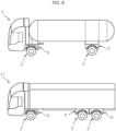
- the drive device is packaged by arranging the pair of drive units 10 to be adjacent to each other in the frame of the body frame casing 5 and connecting the drive units 10 to the body frame casing 5 via the body-connecting parts 32 and 33. That is, the body frame casing 5 in which the pair of left and right drive units 10 are connected by the body-connecting parts 32 and 33 forms a front axle and a rear axle of the vehicle. Therefore, for example, as illustrated in Fig. 8 , a common drive device can be applied to the electric trucks 1' and 1" having different gross vehicle weight, cargo type, wheelbase, and the like. In other words, since it is not necessary to manufacture a drive device for each of electric trucks having different specifications, manufacturing costs can be reduced.
- the electric truck 1' in Fig. 8 is one having a single-axle on the front wheel side and a single-axle also on the rear wheel side
- the electric truck 1" in Fig. 8 is a single-axle truck on the front wheel side and a dual-axle truck on the rear wheel side.
- the steering shaft 30a is disposed equidistant from each of the pair of mounting frame bodies 5A. That is, the double-tire 2 is steered at the center in the front-rear direction within the frame of the body frame casing 5, so that the arrangement balance can be improved.
- the suspension part 20 is an air suspension including the outer tube 21 and the inner tube 22, or a hybrid of an air suspension and the coil spring 28, the suspension part can be selected based on the load and application. Alternatively, a hydraulic suspension or an electromagnetic suspension may be employed.
- the low frictional members 23 and 35 and the thrust plate 34 are not essential and can be omitted.
- the structure for restricting the relative rotation between the outer tube 21 and the inner tube 22 is not limited to the link connection by the stabilizer 27.
- the steering gear part 30 may be realized using gears other than the spur gear 30c and the annular gear 30d.
- the range of the steering angle of the double-tire 2 may be set according to the required turning radius.
- the drive device is packaged by arranging the pair of drive units 10 adjacent to each other in the vehicle width direction in the frame of the body frame casing 5, the method of mounting the drive device on the vehicle body is not limited to this.
- the drive device may be connected to a pair of left and right chassis frames extending in the front-rear direction.
- the hinge parts 40 are not essential and may be omitted.
- a truck having a larger vehicle weight than a passenger car has been described.
- a drive device for a vehicle having a steering performance of a steering angle of 0° to 180° while satisfying a desired suspension performance may be provided.
- the double-tire is not an essential component and may be a single-tire.
- a drive unit including a drive unit housing integrally accommodating a motor, a reducer, and a final gear is provided for each single-tire arranged on each of the left and right sides of the electric vehicle, and a suspension part and a steering gear part are provided integrally above the final gear.
- a drive device since the single-tires are individually driven and individually steered, for example, a steering angle of 0° to 180° can be realized, and the turning radius can be reduced. Therefore, it is possible to provide a drive device for an electric vehicle having a steering performance of a steering angle of 0° to 180° while satisfying a desired suspension performance.
Landscapes
- Engineering & Computer Science (AREA)
- Mechanical Engineering (AREA)
- Chemical & Material Sciences (AREA)
- Combustion & Propulsion (AREA)
- Transportation (AREA)
- Vehicle Body Suspensions (AREA)
- Arrangement Or Mounting Of Propulsion Units For Vehicles (AREA)
- Steering-Linkage Mechanisms And Four-Wheel Steering (AREA)
Claims (7)
- Camion électrique (1) muni de pneus doubles (2), comportant un dispositif d'entraînement comportant :des unités d'entraînement (10) dont chacune inclut un carter d'unité d'entraînement (10) recevant un moteur (11) d'un seul tenant qui génère de la puissance d'entraînement, un réducteur (12) qui réduit une vitesse de rotation du moteur (11), et un engrenage final (14) qui est relié au réducteur (12) et transfère la puissance d'entraînement du moteur (11) à un arbre d'entraînement (13) du pneu double (2),les unités d'entraînement (10) étant prévues pour chacun des pneus doubles (2) sur des côtés gauche et droit du camion électrique (1) ;l'arbre d'entraînement (13) du pneu double (2) s'étendant dans une direction de largeur de véhicule avec le camion (1) se déplaçant vers l'avant en ligne droite ;l'engrenage final (14) étant positionné sur un centre de deux roues (2A) constituant le pneu double (2) dans la direction de largeur de véhicule et répartissant la puissance d'entraînement amplifiée par le réducteur (12) aux deux roues (2A) ; etle dispositif d'entraînement comporte en outre :une partie de suspension (20) ; etune partie d'engrenage de direction (30) agencée au-dessus de la partie de suspension (20) et intégrée dans celle-ci et configurée pour diriger le pneu double (2) ; etla partie de suspension (20) et la partie d'engrenage de direction (30) sont intégrées d'un seul tenant au-dessus de l'engrenage final (14).
- Camion électrique (1) selon la revendication 1, dans lequel la partie de suspension (20) et la partie d'engrenage de direction (30) sont disposées au-dessus d'un espace entre les deux roues (2A).
- Camion électrique (1) selon la revendication 1 ou 2, dans lequel la partie de suspension (20) est une suspension pneumatique comportant : un tube extérieur (21) centré sur un arbre de direction (30a) du pneu double (2) ; et un tube intérieur (22) étant concentrique au tube extérieur (21), pouvant glisser le long d'une face circonférentielle intérieure du tube extérieur (21) dans une direction axiale, et étant incapable de tourner de manière relative par rapport au tube extérieur (21).
- Camion électrique (1) selon la revendication 3, dans lequel la partie de suspension (20) comporte en outre un ressort hélicoïdal (28) entourant le tube extérieur (21) et le tube intérieur (22).
- Camion électrique (1) selon la revendication 3 ou 4, dans lequel la partie de suspension (20) comporte en outre un élément à faible frottement (23) étant agencé à un point où le tube extérieur (21) est amené en contact glissant avec le tube intérieur (22) et réduisant un frottement de glissement du tube extérieur (21) avec le tube intérieur (21).
- Camion électrique selon l'une quelconque des revendications 1 à 5, dans lequel la partie d'engrenage de direction (30) est configurée pour diriger le pneu double (2) jusqu'à 90° vers la gauche et vers la droite en prenant pour hypothèse qu'un angle de braquage du pneu double (2) dans un état où le camion électrique (1) se déplace vers l'avant en ligne droite, est égal à 0°.
- Camion électrique (1) selon l'une quelconque des revendications 1 à 6, dans lequel l'engrenage final (14) est inclus dans un engrenage différentiel.
Applications Claiming Priority (2)
| Application Number | Priority Date | Filing Date | Title |
|---|---|---|---|
| JP2020010654A JP7348092B2 (ja) | 2020-01-27 | 2020-01-27 | 電動トラック用の駆動装置 |
| PCT/JP2020/045613 WO2021153013A1 (fr) | 2020-01-27 | 2020-12-08 | Dispositif d'entraînement de chariot électrique |
Publications (3)
| Publication Number | Publication Date |
|---|---|
| EP4094964A1 EP4094964A1 (fr) | 2022-11-30 |
| EP4094964A4 EP4094964A4 (fr) | 2023-07-19 |
| EP4094964B1 true EP4094964B1 (fr) | 2025-02-19 |
Family
ID=77078988
Family Applications (1)
| Application Number | Title | Priority Date | Filing Date |
|---|---|---|---|
| EP20916288.2A Active EP4094964B1 (fr) | 2020-01-27 | 2020-12-08 | Camion électrique |
Country Status (5)
| Country | Link |
|---|---|
| US (1) | US11865923B2 (fr) |
| EP (1) | EP4094964B1 (fr) |
| JP (1) | JP7348092B2 (fr) |
| CN (1) | CN115023386B (fr) |
| WO (1) | WO2021153013A1 (fr) |
Families Citing this family (3)
| Publication number | Priority date | Publication date | Assignee | Title |
|---|---|---|---|---|
| JP7348092B2 (ja) * | 2020-01-27 | 2023-09-20 | ダイムラー トラック エージー | 電動トラック用の駆動装置 |
| JP7348093B2 (ja) * | 2020-01-27 | 2023-09-20 | ダイムラー トラック エージー | 電動トラック用の駆動装置 |
| US12466485B1 (en) * | 2025-02-27 | 2025-11-11 | Workhorse Group Inc. | Land vehicles incorporating front and rear powertrain units, powertrain units, and components therefor |
Family Cites Families (42)
| Publication number | Priority date | Publication date | Assignee | Title |
|---|---|---|---|---|
| US3049361A (en) | 1958-08-22 | 1962-08-14 | Ronning Adolph | Multi-compensating wheel suspension |
| US3770074A (en) * | 1972-04-24 | 1973-11-06 | Gen Motors Corp | Reduction drive for electric axle |
| CA1279582C (fr) * | 1986-01-29 | 1991-01-29 | Katsuhiko Iijima | Entrainement electrique de roues |
| US5289905A (en) * | 1990-09-13 | 1994-03-01 | Parmac, Inc. | Hydrodynamic retarder for large off-road electric wheel driven vehicles |
| DE19709588C1 (de) * | 1997-03-08 | 1998-10-01 | Zahnradfabrik Friedrichshafen | Scheibenbremsenanordnung für einen Einzelradantrieb |
| PE20020088A1 (es) | 2000-01-20 | 2002-02-13 | Kress Corp | Camion volquete para todo terreno fuera de carretera |
| AU3101901A (en) * | 2000-01-20 | 2001-07-31 | Kress Corporation | Off-highway off-road dump truck |
| US8155834B2 (en) * | 2007-07-30 | 2012-04-10 | Hitachi Construction Machinery Co., Ltd. | Traveling drive unit for working vehicle |
| WO2010147100A1 (fr) | 2009-06-19 | 2010-12-23 | 国立大学法人豊橋技術科学大学 | Mécanisme d'entraînement dirigeable et véhicule mobile omnidirectionnel |
| EP2360047B1 (fr) * | 2010-02-15 | 2012-07-25 | Hitachi Construction Machinery Co., Ltd. | Unité de commande de véhicule pour camion-benne |
| ES2393447T3 (es) * | 2010-05-28 | 2012-12-21 | John Victor Gano | Conjunto de rueda omidireccional y vehículo omidireccional |
| WO2012011921A1 (fr) | 2010-07-23 | 2012-01-26 | Navistar Canada, Inc. | Essieux indépendants en prise directe à roues jumelées |
| US20120018983A1 (en) * | 2010-07-23 | 2012-01-26 | Navistar Canada, Inc. | Independent hydraulic servo drive steering for between-the-duals direct drive equalizing beam suspension |
| US8733478B2 (en) * | 2010-07-29 | 2014-05-27 | Chapman/Leonard Studio Equipment, Inc. | Camera crane mobile base |
| JP5496973B2 (ja) * | 2011-09-06 | 2014-05-21 | 日立建機株式会社 | ダンプトラックの走行駆動装置 |
| JP5472870B2 (ja) * | 2011-12-13 | 2014-04-16 | 晴夫 大谷 | 自動車用の走行操舵装置 |
| JP5829998B2 (ja) * | 2012-06-29 | 2015-12-09 | 日立建機株式会社 | ダンプトラックの走行駆動装置 |
| DE102015212574A1 (de) * | 2015-07-06 | 2017-01-12 | Zf Friedrichshafen Ag | Radträger |
| JP6670571B2 (ja) | 2015-09-28 | 2020-03-25 | Ntn株式会社 | インホイールモータ駆動装置とストラット式サスペンション装置の連結構造 |
| US10207751B2 (en) | 2016-05-09 | 2019-02-19 | Nikola Motor Company Llc | Motor gearbox assembly |
| US20190248233A1 (en) * | 2016-06-17 | 2019-08-15 | The University Of Sydney | Drive module |
| KR101793169B1 (ko) | 2016-08-26 | 2017-11-03 | 주식회사 마루이엔지 | 전동식 구동 바퀴의 조향축 회전 장치 |
| US10293854B2 (en) * | 2016-10-05 | 2019-05-21 | Dreco Energy Services Ulc | Movable rig and steering system |
| CN106394153B (zh) * | 2016-11-25 | 2019-10-29 | 山东大学 | 一种集成液压制动与悬挂系统的行走和转向伺服驱动轮 |
| WO2019014479A1 (fr) * | 2017-07-12 | 2019-01-17 | Axle Tech International Ip Holdings, Llc. | Ensemble essieu pour véhicule à plancher bas |
| NL2019300B1 (en) * | 2017-07-20 | 2019-02-12 | E Traction Europe Bv | In-wheel electric motor provided with an inverter and method of manufacturing such an in-wheel electric motor. |
| NL2019303B1 (en) * | 2017-07-20 | 2019-02-12 | E Traction Europe Bv | In-wheel electric motor provided with a control system |
| JP6703965B2 (ja) | 2017-07-28 | 2020-06-03 | ダイムラー・アクチェンゲゼルシャフトDaimler AG | 電動トラックの駆動装置 |
| US20190193784A1 (en) | 2017-12-21 | 2019-06-27 | Disney Enterprises, Inc. | Non-scrubbing vertical drive unit for a trackless or free roaming vehicle with zero turn radius |
| JP6963213B2 (ja) * | 2017-12-25 | 2021-11-05 | トヨタ自動車株式会社 | ストラット式サスペンション装置 |
| CN107989945B (zh) | 2017-12-28 | 2024-05-10 | 武汉梦马易腾智能汽车科技有限公司 | 油气弹簧、车轮的转向机构、车轮及车辆 |
| CN119636298A (zh) * | 2018-05-10 | 2025-03-18 | 艾里逊变速箱公司 | 用于低底盘车辆的车桥组件 |
| CN108638839B (zh) * | 2018-05-14 | 2019-09-27 | 清华大学 | 一种低地板电动桥总成 |
| CN119928540A (zh) * | 2018-09-27 | 2025-05-06 | 艾里逊变速箱公司 | 电动轮轴组件 |
| WO2020072958A1 (fr) * | 2018-10-04 | 2020-04-09 | Allison Transmission, Inc. | Ensemble d'essieu électrique pour véhicule à plancher bas |
| CN109130839B (zh) * | 2018-10-09 | 2020-06-30 | 清华大学 | 一种适用于双胎并装车轮的电动轮总成、车桥及车辆 |
| JP7111585B2 (ja) * | 2018-11-08 | 2022-08-02 | 日立建機株式会社 | ダンプトラック |
| CN110371216A (zh) | 2019-07-02 | 2019-10-25 | 三峡大学 | 一种用于agv小车的转向行走机构及控制方法 |
| US11498410B2 (en) * | 2019-10-23 | 2022-11-15 | Deere & Company | Powered axle for dual wheel work vehicle |
| CN111002818A (zh) * | 2019-12-23 | 2020-04-14 | 福建工程学院 | 一种可应用于蜂群式运载的运载装置 |
| JP7348093B2 (ja) * | 2020-01-27 | 2023-09-20 | ダイムラー トラック エージー | 電動トラック用の駆動装置 |
| JP7348092B2 (ja) * | 2020-01-27 | 2023-09-20 | ダイムラー トラック エージー | 電動トラック用の駆動装置 |
-
2020
- 2020-01-27 JP JP2020010654A patent/JP7348092B2/ja active Active
- 2020-12-08 CN CN202080094659.1A patent/CN115023386B/zh active Active
- 2020-12-08 EP EP20916288.2A patent/EP4094964B1/fr active Active
- 2020-12-08 US US17/782,490 patent/US11865923B2/en active Active
- 2020-12-08 WO PCT/JP2020/045613 patent/WO2021153013A1/fr not_active Ceased
Also Published As
| Publication number | Publication date |
|---|---|
| US20220410693A1 (en) | 2022-12-29 |
| EP4094964A4 (fr) | 2023-07-19 |
| US11865923B2 (en) | 2024-01-09 |
| JP7348092B2 (ja) | 2023-09-20 |
| JP2021115961A (ja) | 2021-08-10 |
| CN115023386B (zh) | 2024-04-19 |
| EP4094964A1 (fr) | 2022-11-30 |
| CN115023386A (zh) | 2022-09-06 |
| WO2021153013A1 (fr) | 2021-08-05 |
Similar Documents
| Publication | Publication Date | Title |
|---|---|---|
| EP3241691B1 (fr) | Module de suspension comportant un ensemble de chassis auxiliaire | |
| EP4094964B1 (fr) | Camion électrique | |
| US7644938B2 (en) | In-wheel suspension | |
| EP4094965B1 (fr) | Camion électrique | |
| EP4094966B1 (fr) | Camion électrique | |
| WO2022134087A1 (fr) | Structure de suspension, système de module d'angle et véhicule automobile | |
| US20230294512A1 (en) | Drive configuration for vehicle | |
| WO2014178250A1 (fr) | Dispositif de suspension de roue menée de moteur-roue | |
| JP2008168804A (ja) | 車両用駆動装置の配設構造 | |
| CN117508340A (zh) | 一种角模块和车辆 | |
| US20230150575A1 (en) | Independent corner module | |
| JP2005306090A (ja) | 自動車のモータ駆動システム | |
| CN120229293A (zh) | 具有线性致动器的独立转向装置及包括该装置的车辆 | |
| JP2005343354A (ja) | 自動車のモータ駆動システム | |
| RU2743346C1 (ru) | Колесный блок с управляемой подвеской | |
| RU2740522C1 (ru) | Управляемая подвеска двухколесного блока | |
| CN223574196U (zh) | 模块化驱动转向悬挂一体桥 | |
| CN117622303A (zh) | 单纵臂悬架、角模块结构和车辆 | |
| KR20260024340A (ko) | 인휠 모터 시스템용 코너 모듈 | |
| CN121201201A (zh) | 车辆角模块及车辆 | |
| CN117698362A (zh) | 悬架系统及车辆 | |
| CN119796317A (zh) | 转向系统、底盘总成和车辆 | |
| JP2012001017A (ja) | 車両用駆動装置 | |
| JPH01275216A (ja) | 車両用サスペンション装置 |
Legal Events
| Date | Code | Title | Description |
|---|---|---|---|
| STAA | Information on the status of an ep patent application or granted ep patent |
Free format text: STATUS: THE INTERNATIONAL PUBLICATION HAS BEEN MADE |
|
| PUAI | Public reference made under article 153(3) epc to a published international application that has entered the european phase |
Free format text: ORIGINAL CODE: 0009012 |
|
| STAA | Information on the status of an ep patent application or granted ep patent |
Free format text: STATUS: REQUEST FOR EXAMINATION WAS MADE |
|
| 17P | Request for examination filed |
Effective date: 20220825 |
|
| AK | Designated contracting states |
Kind code of ref document: A1 Designated state(s): AL AT BE BG CH CY CZ DE DK EE ES FI FR GB GR HR HU IE IS IT LI LT LU LV MC MK MT NL NO PL PT RO RS SE SI SK SM TR |
|
| RAP1 | Party data changed (applicant data changed or rights of an application transferred) |
Owner name: DAIMLER TRUCK AG |
|
| DAV | Request for validation of the european patent (deleted) | ||
| DAX | Request for extension of the european patent (deleted) | ||
| A4 | Supplementary search report drawn up and despatched |
Effective date: 20230621 |
|
| RIC1 | Information provided on ipc code assigned before grant |
Ipc: B62D 7/15 20060101ALI20230615BHEP Ipc: B62D 7/04 20060101ALI20230615BHEP Ipc: B60K 1/00 20060101ALI20230615BHEP Ipc: B60G 11/58 20060101ALI20230615BHEP Ipc: B60G 11/56 20060101ALI20230615BHEP Ipc: B60G 11/28 20060101ALI20230615BHEP Ipc: B60K 1/02 20060101ALI20230615BHEP Ipc: B62D 7/14 20060101ALI20230615BHEP Ipc: B60G 11/27 20060101ALI20230615BHEP Ipc: B60G 11/14 20060101ALI20230615BHEP Ipc: B60K 7/00 20060101AFI20230615BHEP |
|
| STAA | Information on the status of an ep patent application or granted ep patent |
Free format text: STATUS: EXAMINATION IS IN PROGRESS |
|
| 17Q | First examination report despatched |
Effective date: 20240419 |
|
| GRAP | Despatch of communication of intention to grant a patent |
Free format text: ORIGINAL CODE: EPIDOSNIGR1 |
|
| STAA | Information on the status of an ep patent application or granted ep patent |
Free format text: STATUS: GRANT OF PATENT IS INTENDED |
|
| INTG | Intention to grant announced |
Effective date: 20240909 |
|
| P01 | Opt-out of the competence of the unified patent court (upc) registered |
Free format text: CASE NUMBER: APP_60039/2024 Effective date: 20241106 |
|
| GRAS | Grant fee paid |
Free format text: ORIGINAL CODE: EPIDOSNIGR3 |
|
| GRAA | (expected) grant |
Free format text: ORIGINAL CODE: 0009210 |
|
| STAA | Information on the status of an ep patent application or granted ep patent |
Free format text: STATUS: THE PATENT HAS BEEN GRANTED |
|
| AK | Designated contracting states |
Kind code of ref document: B1 Designated state(s): AL AT BE BG CH CY CZ DE DK EE ES FI FR GB GR HR HU IE IS IT LI LT LU LV MC MK MT NL NO PL PT RO RS SE SI SK SM TR |
|
| REG | Reference to a national code |
Ref country code: GB Ref legal event code: FG4D |
|
| REG | Reference to a national code |
Ref country code: CH Ref legal event code: EP |
|
| REG | Reference to a national code |
Ref country code: IE Ref legal event code: FG4D |
|
| REG | Reference to a national code |
Ref country code: DE Ref legal event code: R096 Ref document number: 602020046580 Country of ref document: DE |
|
| REG | Reference to a national code |
Ref country code: NL Ref legal event code: MP Effective date: 20250219 |
|
| PG25 | Lapsed in a contracting state [announced via postgrant information from national office to epo] |
Ref country code: RS Free format text: LAPSE BECAUSE OF FAILURE TO SUBMIT A TRANSLATION OF THE DESCRIPTION OR TO PAY THE FEE WITHIN THE PRESCRIBED TIME-LIMIT Effective date: 20250519 |
|
| PG25 | Lapsed in a contracting state [announced via postgrant information from national office to epo] |
Ref country code: FI Free format text: LAPSE BECAUSE OF FAILURE TO SUBMIT A TRANSLATION OF THE DESCRIPTION OR TO PAY THE FEE WITHIN THE PRESCRIBED TIME-LIMIT Effective date: 20250219 |
|
| PG25 | Lapsed in a contracting state [announced via postgrant information from national office to epo] |
Ref country code: PL Free format text: LAPSE BECAUSE OF FAILURE TO SUBMIT A TRANSLATION OF THE DESCRIPTION OR TO PAY THE FEE WITHIN THE PRESCRIBED TIME-LIMIT Effective date: 20250219 |
|
| PG25 | Lapsed in a contracting state [announced via postgrant information from national office to epo] |
Ref country code: ES Free format text: LAPSE BECAUSE OF FAILURE TO SUBMIT A TRANSLATION OF THE DESCRIPTION OR TO PAY THE FEE WITHIN THE PRESCRIBED TIME-LIMIT Effective date: 20250219 |
|
| REG | Reference to a national code |
Ref country code: LT Ref legal event code: MG9D |
|
| PG25 | Lapsed in a contracting state [announced via postgrant information from national office to epo] |
Ref country code: NO Free format text: LAPSE BECAUSE OF FAILURE TO SUBMIT A TRANSLATION OF THE DESCRIPTION OR TO PAY THE FEE WITHIN THE PRESCRIBED TIME-LIMIT Effective date: 20250519 Ref country code: IS Free format text: LAPSE BECAUSE OF FAILURE TO SUBMIT A TRANSLATION OF THE DESCRIPTION OR TO PAY THE FEE WITHIN THE PRESCRIBED TIME-LIMIT Effective date: 20250619 |
|
| PG25 | Lapsed in a contracting state [announced via postgrant information from national office to epo] |
Ref country code: NL Free format text: LAPSE BECAUSE OF FAILURE TO SUBMIT A TRANSLATION OF THE DESCRIPTION OR TO PAY THE FEE WITHIN THE PRESCRIBED TIME-LIMIT Effective date: 20250219 |
|
| PG25 | Lapsed in a contracting state [announced via postgrant information from national office to epo] |
Ref country code: HR Free format text: LAPSE BECAUSE OF FAILURE TO SUBMIT A TRANSLATION OF THE DESCRIPTION OR TO PAY THE FEE WITHIN THE PRESCRIBED TIME-LIMIT Effective date: 20250219 |
|
| PG25 | Lapsed in a contracting state [announced via postgrant information from national office to epo] |
Ref country code: PT Free format text: LAPSE BECAUSE OF FAILURE TO SUBMIT A TRANSLATION OF THE DESCRIPTION OR TO PAY THE FEE WITHIN THE PRESCRIBED TIME-LIMIT Effective date: 20250620 Ref country code: LV Free format text: LAPSE BECAUSE OF FAILURE TO SUBMIT A TRANSLATION OF THE DESCRIPTION OR TO PAY THE FEE WITHIN THE PRESCRIBED TIME-LIMIT Effective date: 20250219 |
|
| PG25 | Lapsed in a contracting state [announced via postgrant information from national office to epo] |
Ref country code: BG Free format text: LAPSE BECAUSE OF FAILURE TO SUBMIT A TRANSLATION OF THE DESCRIPTION OR TO PAY THE FEE WITHIN THE PRESCRIBED TIME-LIMIT Effective date: 20250219 Ref country code: GR Free format text: LAPSE BECAUSE OF FAILURE TO SUBMIT A TRANSLATION OF THE DESCRIPTION OR TO PAY THE FEE WITHIN THE PRESCRIBED TIME-LIMIT Effective date: 20250520 |
|
| REG | Reference to a national code |
Ref country code: AT Ref legal event code: MK05 Ref document number: 1767996 Country of ref document: AT Kind code of ref document: T Effective date: 20250219 |
|
| PG25 | Lapsed in a contracting state [announced via postgrant information from national office to epo] |
Ref country code: SE Free format text: LAPSE BECAUSE OF FAILURE TO SUBMIT A TRANSLATION OF THE DESCRIPTION OR TO PAY THE FEE WITHIN THE PRESCRIBED TIME-LIMIT Effective date: 20250219 |
|
| PG25 | Lapsed in a contracting state [announced via postgrant information from national office to epo] |
Ref country code: SM Free format text: LAPSE BECAUSE OF FAILURE TO SUBMIT A TRANSLATION OF THE DESCRIPTION OR TO PAY THE FEE WITHIN THE PRESCRIBED TIME-LIMIT Effective date: 20250219 |
|
| PG25 | Lapsed in a contracting state [announced via postgrant information from national office to epo] |
Ref country code: DK Free format text: LAPSE BECAUSE OF FAILURE TO SUBMIT A TRANSLATION OF THE DESCRIPTION OR TO PAY THE FEE WITHIN THE PRESCRIBED TIME-LIMIT Effective date: 20250219 |
|
| PG25 | Lapsed in a contracting state [announced via postgrant information from national office to epo] |
Ref country code: IT Free format text: LAPSE BECAUSE OF FAILURE TO SUBMIT A TRANSLATION OF THE DESCRIPTION OR TO PAY THE FEE WITHIN THE PRESCRIBED TIME-LIMIT Effective date: 20250219 |
|
| PG25 | Lapsed in a contracting state [announced via postgrant information from national office to epo] |
Ref country code: AT Free format text: LAPSE BECAUSE OF FAILURE TO SUBMIT A TRANSLATION OF THE DESCRIPTION OR TO PAY THE FEE WITHIN THE PRESCRIBED TIME-LIMIT Effective date: 20250219 |
|
| PG25 | Lapsed in a contracting state [announced via postgrant information from national office to epo] |
Ref country code: EE Free format text: LAPSE BECAUSE OF FAILURE TO SUBMIT A TRANSLATION OF THE DESCRIPTION OR TO PAY THE FEE WITHIN THE PRESCRIBED TIME-LIMIT Effective date: 20250219 Ref country code: CZ Free format text: LAPSE BECAUSE OF FAILURE TO SUBMIT A TRANSLATION OF THE DESCRIPTION OR TO PAY THE FEE WITHIN THE PRESCRIBED TIME-LIMIT Effective date: 20250219 |
|
| PG25 | Lapsed in a contracting state [announced via postgrant information from national office to epo] |
Ref country code: RO Free format text: LAPSE BECAUSE OF FAILURE TO SUBMIT A TRANSLATION OF THE DESCRIPTION OR TO PAY THE FEE WITHIN THE PRESCRIBED TIME-LIMIT Effective date: 20250219 |
|
| PG25 | Lapsed in a contracting state [announced via postgrant information from national office to epo] |
Ref country code: SK Free format text: LAPSE BECAUSE OF FAILURE TO SUBMIT A TRANSLATION OF THE DESCRIPTION OR TO PAY THE FEE WITHIN THE PRESCRIBED TIME-LIMIT Effective date: 20250219 |
|
| REG | Reference to a national code |
Ref country code: DE Ref legal event code: R097 Ref document number: 602020046580 Country of ref document: DE |
|
| PLBE | No opposition filed within time limit |
Free format text: ORIGINAL CODE: 0009261 |
|
| STAA | Information on the status of an ep patent application or granted ep patent |
Free format text: STATUS: NO OPPOSITION FILED WITHIN TIME LIMIT |
|
| PGFP | Annual fee paid to national office [announced via postgrant information from national office to epo] |
Ref country code: GB Payment date: 20251223 Year of fee payment: 6 |
|
| PGFP | Annual fee paid to national office [announced via postgrant information from national office to epo] |
Ref country code: FR Payment date: 20251223 Year of fee payment: 6 |
|
| 26N | No opposition filed |
Effective date: 20251120 |
|
| PGFP | Annual fee paid to national office [announced via postgrant information from national office to epo] |
Ref country code: DE Payment date: 20251229 Year of fee payment: 6 |