EP4094965B1 - Elektrischer lastkraftwagen - Google Patents
Elektrischer lastkraftwagen Download PDFInfo
- Publication number
- EP4094965B1 EP4094965B1 EP20917252.7A EP20917252A EP4094965B1 EP 4094965 B1 EP4094965 B1 EP 4094965B1 EP 20917252 A EP20917252 A EP 20917252A EP 4094965 B1 EP4094965 B1 EP 4094965B1
- Authority
- EP
- European Patent Office
- Prior art keywords
- drive
- outer tube
- electric truck
- steering
- parts
- Prior art date
- Legal status (The legal status is an assumption and is not a legal conclusion. Google has not performed a legal analysis and makes no representation as to the accuracy of the status listed.)
- Active
Links
Images



Classifications
-
- B—PERFORMING OPERATIONS; TRANSPORTING
- B62—LAND VEHICLES FOR TRAVELLING OTHERWISE THAN ON RAILS
- B62D—MOTOR VEHICLES; TRAILERS
- B62D7/00—Steering linkage; Stub axles or their mountings
- B62D7/02—Steering linkage; Stub axles or their mountings for pivoted bogies
- B62D7/04—Steering linkage; Stub axles or their mountings for pivoted bogies with more than one wheel
-
- B—PERFORMING OPERATIONS; TRANSPORTING
- B60—VEHICLES IN GENERAL
- B60G—VEHICLE SUSPENSION ARRANGEMENTS
- B60G11/00—Resilient suspensions characterised by arrangement, location or kind of springs
- B60G11/26—Resilient suspensions characterised by arrangement, location or kind of springs having fluid springs only, e.g. hydropneumatic springs
- B60G11/27—Resilient suspensions characterised by arrangement, location or kind of springs having fluid springs only, e.g. hydropneumatic springs wherein the fluid is a gas
-
- B—PERFORMING OPERATIONS; TRANSPORTING
- B60—VEHICLES IN GENERAL
- B60G—VEHICLE SUSPENSION ARRANGEMENTS
- B60G11/00—Resilient suspensions characterised by arrangement, location or kind of springs
- B60G11/26—Resilient suspensions characterised by arrangement, location or kind of springs having fluid springs only, e.g. hydropneumatic springs
- B60G11/28—Resilient suspensions characterised by arrangement, location or kind of springs having fluid springs only, e.g. hydropneumatic springs characterised by means specially adapted for attaching the spring to axle or sprung part of the vehicle
-
- B—PERFORMING OPERATIONS; TRANSPORTING
- B60—VEHICLES IN GENERAL
- B60G—VEHICLE SUSPENSION ARRANGEMENTS
- B60G11/00—Resilient suspensions characterised by arrangement, location or kind of springs
- B60G11/32—Resilient suspensions characterised by arrangement, location or kind of springs having springs of different kinds
- B60G11/48—Resilient suspensions characterised by arrangement, location or kind of springs having springs of different kinds not including leaf springs
- B60G11/56—Resilient suspensions characterised by arrangement, location or kind of springs having springs of different kinds not including leaf springs having helical, spiral or coil springs, and also fluid springs
-
- B—PERFORMING OPERATIONS; TRANSPORTING
- B60—VEHICLES IN GENERAL
- B60G—VEHICLE SUSPENSION ARRANGEMENTS
- B60G11/00—Resilient suspensions characterised by arrangement, location or kind of springs
- B60G11/32—Resilient suspensions characterised by arrangement, location or kind of springs having springs of different kinds
- B60G11/48—Resilient suspensions characterised by arrangement, location or kind of springs having springs of different kinds not including leaf springs
- B60G11/56—Resilient suspensions characterised by arrangement, location or kind of springs having springs of different kinds not including leaf springs having helical, spiral or coil springs, and also fluid springs
- B60G11/58—Resilient suspensions characterised by arrangement, location or kind of springs having springs of different kinds not including leaf springs having helical, spiral or coil springs, and also fluid springs arranged coaxially
-
- B—PERFORMING OPERATIONS; TRANSPORTING
- B60—VEHICLES IN GENERAL
- B60K—ARRANGEMENT OR MOUNTING OF PROPULSION UNITS OR OF TRANSMISSIONS IN VEHICLES; ARRANGEMENT OR MOUNTING OF PLURAL DIVERSE PRIME-MOVERS IN VEHICLES; AUXILIARY DRIVES FOR VEHICLES; INSTRUMENTATION OR DASHBOARDS FOR VEHICLES; ARRANGEMENTS IN CONNECTION WITH COOLING, AIR INTAKE, GAS EXHAUST OR FUEL SUPPLY OF PROPULSION UNITS IN VEHICLES
- B60K1/00—Arrangement or mounting of electrical propulsion units
- B60K1/02—Arrangement or mounting of electrical propulsion units comprising more than one electric motor
-
- B—PERFORMING OPERATIONS; TRANSPORTING
- B60—VEHICLES IN GENERAL
- B60K—ARRANGEMENT OR MOUNTING OF PROPULSION UNITS OR OF TRANSMISSIONS IN VEHICLES; ARRANGEMENT OR MOUNTING OF PLURAL DIVERSE PRIME-MOVERS IN VEHICLES; AUXILIARY DRIVES FOR VEHICLES; INSTRUMENTATION OR DASHBOARDS FOR VEHICLES; ARRANGEMENTS IN CONNECTION WITH COOLING, AIR INTAKE, GAS EXHAUST OR FUEL SUPPLY OF PROPULSION UNITS IN VEHICLES
- B60K7/00—Disposition of motor in, or adjacent to, traction wheel
- B60K7/0007—Disposition of motor in, or adjacent to, traction wheel the motor being electric
-
- B—PERFORMING OPERATIONS; TRANSPORTING
- B62—LAND VEHICLES FOR TRAVELLING OTHERWISE THAN ON RAILS
- B62D—MOTOR VEHICLES; TRAILERS
- B62D7/00—Steering linkage; Stub axles or their mountings
- B62D7/06—Steering linkage; Stub axles or their mountings for individually-pivoted wheels, e.g. on king-pins
- B62D7/14—Steering linkage; Stub axles or their mountings for individually-pivoted wheels, e.g. on king-pins the pivotal axes being situated in more than one plane transverse to the longitudinal centre line of the vehicle, e.g. all-wheel steering
-
- B—PERFORMING OPERATIONS; TRANSPORTING
- B62—LAND VEHICLES FOR TRAVELLING OTHERWISE THAN ON RAILS
- B62D—MOTOR VEHICLES; TRAILERS
- B62D7/00—Steering linkage; Stub axles or their mountings
- B62D7/06—Steering linkage; Stub axles or their mountings for individually-pivoted wheels, e.g. on king-pins
- B62D7/14—Steering linkage; Stub axles or their mountings for individually-pivoted wheels, e.g. on king-pins the pivotal axes being situated in more than one plane transverse to the longitudinal centre line of the vehicle, e.g. all-wheel steering
- B62D7/15—Steering linkage; Stub axles or their mountings for individually-pivoted wheels, e.g. on king-pins the pivotal axes being situated in more than one plane transverse to the longitudinal centre line of the vehicle, e.g. all-wheel steering characterised by means varying the ratio between the steering angles of the steered wheels
- B62D7/1509—Steering linkage; Stub axles or their mountings for individually-pivoted wheels, e.g. on king-pins the pivotal axes being situated in more than one plane transverse to the longitudinal centre line of the vehicle, e.g. all-wheel steering characterised by means varying the ratio between the steering angles of the steered wheels with different steering modes, e.g. crab-steering, or steering specially adapted for reversing of the vehicle
-
- B—PERFORMING OPERATIONS; TRANSPORTING
- B60—VEHICLES IN GENERAL
- B60G—VEHICLE SUSPENSION ARRANGEMENTS
- B60G2200/00—Indexing codes relating to suspension types
- B60G2200/40—Indexing codes relating to the wheels in the suspensions
- B60G2200/422—Driving wheels or live axles
-
- B—PERFORMING OPERATIONS; TRANSPORTING
- B60—VEHICLES IN GENERAL
- B60G—VEHICLE SUSPENSION ARRANGEMENTS
- B60G2200/00—Indexing codes relating to suspension types
- B60G2200/40—Indexing codes relating to the wheels in the suspensions
- B60G2200/44—Indexing codes relating to the wheels in the suspensions steerable
-
- B—PERFORMING OPERATIONS; TRANSPORTING
- B60—VEHICLES IN GENERAL
- B60G—VEHICLE SUSPENSION ARRANGEMENTS
- B60G2202/00—Indexing codes relating to the type of spring, damper or actuator
- B60G2202/10—Type of spring
- B60G2202/15—Fluid spring
- B60G2202/152—Pneumatic spring
-
- B—PERFORMING OPERATIONS; TRANSPORTING
- B60—VEHICLES IN GENERAL
- B60G—VEHICLE SUSPENSION ARRANGEMENTS
- B60G2204/00—Indexing codes related to suspensions per se or to auxiliary parts
- B60G2204/10—Mounting of suspension elements
- B60G2204/12—Mounting of springs or dampers
- B60G2204/124—Mounting of coil springs
-
- B—PERFORMING OPERATIONS; TRANSPORTING
- B60—VEHICLES IN GENERAL
- B60G—VEHICLE SUSPENSION ARRANGEMENTS
- B60G2204/00—Indexing codes related to suspensions per se or to auxiliary parts
- B60G2204/10—Mounting of suspension elements
- B60G2204/12—Mounting of springs or dampers
- B60G2204/126—Mounting of pneumatic springs
-
- B—PERFORMING OPERATIONS; TRANSPORTING
- B60—VEHICLES IN GENERAL
- B60G—VEHICLE SUSPENSION ARRANGEMENTS
- B60G2300/00—Indexing codes relating to the type of vehicle
- B60G2300/02—Trucks; Load vehicles
- B60G2300/026—Heavy duty trucks
- B60G2300/0262—Multi-axle trucks
-
- B—PERFORMING OPERATIONS; TRANSPORTING
- B60—VEHICLES IN GENERAL
- B60G—VEHICLE SUSPENSION ARRANGEMENTS
- B60G2300/00—Indexing codes relating to the type of vehicle
- B60G2300/37—Vehicles having steerable wheels mounted on a vertically moving column
-
- B—PERFORMING OPERATIONS; TRANSPORTING
- B60—VEHICLES IN GENERAL
- B60G—VEHICLE SUSPENSION ARRANGEMENTS
- B60G2300/00—Indexing codes relating to the type of vehicle
- B60G2300/50—Electric vehicles; Hybrid vehicles
-
- B—PERFORMING OPERATIONS; TRANSPORTING
- B60—VEHICLES IN GENERAL
- B60K—ARRANGEMENT OR MOUNTING OF PROPULSION UNITS OR OF TRANSMISSIONS IN VEHICLES; ARRANGEMENT OR MOUNTING OF PLURAL DIVERSE PRIME-MOVERS IN VEHICLES; AUXILIARY DRIVES FOR VEHICLES; INSTRUMENTATION OR DASHBOARDS FOR VEHICLES; ARRANGEMENTS IN CONNECTION WITH COOLING, AIR INTAKE, GAS EXHAUST OR FUEL SUPPLY OF PROPULSION UNITS IN VEHICLES
- B60K7/00—Disposition of motor in, or adjacent to, traction wheel
- B60K2007/0038—Disposition of motor in, or adjacent to, traction wheel the motor moving together with the wheel axle
-
- B—PERFORMING OPERATIONS; TRANSPORTING
- B60—VEHICLES IN GENERAL
- B60K—ARRANGEMENT OR MOUNTING OF PROPULSION UNITS OR OF TRANSMISSIONS IN VEHICLES; ARRANGEMENT OR MOUNTING OF PLURAL DIVERSE PRIME-MOVERS IN VEHICLES; AUXILIARY DRIVES FOR VEHICLES; INSTRUMENTATION OR DASHBOARDS FOR VEHICLES; ARRANGEMENTS IN CONNECTION WITH COOLING, AIR INTAKE, GAS EXHAUST OR FUEL SUPPLY OF PROPULSION UNITS IN VEHICLES
- B60K7/00—Disposition of motor in, or adjacent to, traction wheel
- B60K2007/0061—Disposition of motor in, or adjacent to, traction wheel the motor axle being parallel to the wheel axle
-
- B—PERFORMING OPERATIONS; TRANSPORTING
- B60—VEHICLES IN GENERAL
- B60Y—INDEXING SCHEME RELATING TO ASPECTS CROSS-CUTTING VEHICLE TECHNOLOGY
- B60Y2200/00—Type of vehicle
- B60Y2200/10—Road Vehicles
- B60Y2200/14—Trucks; Load vehicles, Busses
- B60Y2200/142—Heavy duty trucks
- B60Y2200/1422—Multi-axle trucks
-
- B—PERFORMING OPERATIONS; TRANSPORTING
- B60—VEHICLES IN GENERAL
- B60Y—INDEXING SCHEME RELATING TO ASPECTS CROSS-CUTTING VEHICLE TECHNOLOGY
- B60Y2200/00—Type of vehicle
- B60Y2200/40—Special vehicles
- B60Y2200/45—Vehicles having steerable wheels mounted on a vertically moving column
Definitions
- the present disclosure relate to an electric truck according to the preamble of claim 1.
- Patent Literature 1 In recent years, from the viewpoint of reducing the environmental load, in the field of commercial vehicles such as trucks, there has been developed an electric truck which does not have an internal combustion engine and is driven only by an electric motor (see Patent Literature 1).
- a drive device used for such an electric truck for example, as shown in Patent Literature 1, a drive device in which a driving motor and a reducer are integrally provided in a differential gear has been considered.
- DE 10 2015 212574 A1 discloses a drive device for an electric truck comprising a drive unit housing which integrally accommodates a motor that generates drive power, a reducer that reduces a rotation speed of the motor, and a final gear that is connected to the reducer and transfers the drive power of the motor to a drive wheel of the electric truck.
- DE 10 2015 212574 A1 discloses the preamble of claim 1.
- CN 107 989 945 A provides an oil-gas spring, a wheel steering mechanism provided with the oil-gas spring, a wheel provided with the oil-gas spring and a vehicle adopting the wheel.
- WO 01/53141 A1 discloses a truck having a frame with a forward end and a rearward end. The rearward end of the frame is supported by at least two wheels coupled to part of the frame.
- the truck also has a forward strut support coupled to the frame near the forward end.
- the truck has at least first and second struct modules coupled to the forward strut support.
- the first and second strut modules each have an independent steering mechanism and at least one wheel and tire assembly.
- Each of the first and second strut modules can also have one or more motors for driving a respective wheel and tire assembly independent of each other wheel and tire assembly of that strut module and of the other strut module.
- WO 2017/214686 A1 each disclose an electric truck comprising a drive device having drive units each of which includes a drive unit housing integrally accommodating a motor that generates drive power, a reducer that reduces a rotation speed of the motor, and a final gear that is connected to the reducer and transfers the drive power of the motor to a drive shaft of the double-tire.
- An electric truck has a tendency of having larger vehicle-body vibration while traveling than a passenger car, and for this reason, a demand arises to improve drive feeling.
- the present disclosure makes it possible to provide a drive device for an electric truck having a steering performance of a steering angle of 0° to 180° while improving drive feeling.
- a drive device for an electric truck according to an embodiment will now be described with reference to accompanying drawings.
- the following embodiment is merely example, so there is no intention to exclude various modifications and applications of techniques not explicitly described in the following embodiment.
- Each of the structures of the present embodiment can be variously modified without departing from the scope of the structure.
- the structures may be appropriately selected, omitted, or combined according to the requirement.
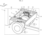
- the drive device is applied to an electric truck 1 that travels only by the drive power of a motor 11 (see FIG. 3 ) without an internal combustion engine.
- the electric truck 1 (hereinafter simply referred to as the "truck 1") including a pair of left and right side frames 1A (also referred to as chassis frames) extending in the front-rear direction of the vehicle and a cab 1B disposed in the front part of the vehicle is illustrated, and the illustration of the body is omitted.
- a frame extending in the vehicle widthwise direction may be provided, or the side frames 1A may be omitted.
- the forward direction of the truck 1 will be referred to as the "front”, and the opposite direction to the front will be referred to as the "rear”.
- the left-right direction is determined with reference to the state of the truck 1 facing forward.
- the left-right direction is orthogonal to the front-rear direction of the vehicle.
- the left-right direction is referred to as a "vehicle width direction”
- the front-rear direction of the vehicle is simply referred to as a "front-rear direction”.
- the truck 1 of the present embodiment includes double-tires 2 each consisting of two drive wheels 2A (drive wheels).
- double-tires 2 each consisting of two drive wheels 2A (drive wheels).
- a pair of left and right double-tires 2 are provided on the front side (front wheel side) of the vehicle, and two pairs of left and right double-tires 2 are provided side by side on the rear side (rear wheel side) of the vehicle, but the number of double-tires 2 in the front-rear direction is not limited to this.
- Each double-tire 2 is provided with one drive unit 10 including the motor 11, and the drive power of the motor 11 is transmitted to the double-tire 2 (drive wheels 2A).
- the configuration of the drive unit 10 will be described below.
- the truck 1 of the present embodiment includes a body frame casing 5 composed of a pair of mounting frame bodies 5A extending in the vehicle width direction, a pair of cross members 5B and a pair of cross members 5C connecting the mounting frame bodies 5A, and body-connecting parts 32 and 33 for connecting the drive unit 10 disposed in the frame of the body frame casing 5 to the respective mounting frame bodies 5A.
- the pair of mounting frame bodies 5A are disposed apart from each other in the front-rear direction.
- Each of the cross members 5B and 5C connects the front and rear mounting frame bodies 5A.
- the pair of left and right drive units 10 are disposed in the frame of the body frame casing 5 so as to be adjacent to each other in the vehicle width direction.
- one body frame casing 5 is provided on the front side (front wheel side) of the vehicle, and two body frame casings 5 are provided on the rear side (rear wheel side) of the vehicle, but the number of body frame casings 5 in front and that in rear are not limited to these.
- the body frame casing 5 in which the pair of left and right drive units 10 are connected by the body-connecting parts 32 and 33 constitutes a front axle and a rear axle of the vehicle.
- the body frame casing 5 of the present embodiment is formed of a rectangular flat plate member in which the front and rear mounting frame bodies 5A extend in the vehicle width direction and the vertical direction.
- the cross members 5B located above the body frame casing 5 are each formed of a member having a U-shaped or hat-shaped cross section extending in the front-rear direction, and connects the flanges at the upper ends of the front and rear mounting frame bodies 5A.
- the cross members 5C located on the sides of the body frame casing 5 are each formed of a flat plate member extending in the front-rear direction and the vertical direction and having a concave portion formed so as to surround the drive wheel 2A. Any one of the cross members 5B and 5C may be omitted.
- the front body-connecting part 32 connects the front side of the drive unit 10 in the frame to the front mounting frame body 5A
- the rear body-connecting part 33 connects the rear side of the drive unit 10 in the frame to the rear mounting frame body 5A.
- the front and rear body-connecting parts 32 and 33 are formed in the same manner (front and rear symmetric). Each of the body-connecting parts 32 and 33 extends in the front-rear direction and is connected to the mounting frame body 5A to constitute a part of the frame of the truck 1.
- a planar mounting face 32a extending in a direction orthogonal to the front-rear direction is provided.
- a pair of connecting side protruding portions 32b protruding rearward is provided.
- the mounting face 32a is a part to be attached to the mounting frame body 5A, and has a fastening hole (not shown).
- the pair of connecting side protruding portions 32b are separated from each other in the vehicle width direction, and have holes 32c penetrating in the vehicle width direction.
- the connecting side protruding portion 32b constitutes a part of a hinge part 40, which will be described below, and is connected to a steering gear part 30, which will also be described below.
- a planar mounting face 33a extending in a direction orthogonal to the front-rear direction is provided.
- a pair of connecting side protruding portions 33b protruding forward and each having a hole 33c are provided.
- the configuration of the mounting face 33a and the connecting side protruding portions 33b are the same as the configuration of the mounting face 32a and the connecting side protruding portions 32b, respectively.
- the drive unit 10 includes the motor 11 that generates drive power, a reducer 12 that reduces a rotation speed of the motor 11, a final gear 14 that is connected to the reducer 12 and transfers the drive power of the motor 11 to a drive shaft 13 of the double-tire 2, and a drive unit housing 15 that integrally accommodates these units. That is, the drive unit housing 15 integrally houses the motor 11, the reducer 12, and the final gear 14.
- the motor 11 functions as an electric motor when the vehicle is driven, and functions as an electric generator when the vehicle is decelerated.
- the reducer 12 decelerates the rotation speed of the motor 11 to amplify the motor torque (drive power).
- the drive shaft 13 is extended in the vehicle width direction with the truck 1 traveling straight forward, and is arranged in pairs on the left and right across the final gear 14.
- the final gear 14 is positioned substantially at the center of the two drive wheels 2A in the vehicle width direction, and distributes the drive power of the motor 11 amplified by the reducer 12 to the two drive wheels 2A.
- the final gear 14 may be included in a differential gear. However, in the double-tire 2, the differential gear can be omitted because the two drive wheels 2A are closer to each other than the normal left and right wheels.
- the drive device of the truck 1 includes a suspension part 20 provided over the final gear 14 in the drive unit housing 15, and a steering gear part 30 provided over the suspension part 20. Further, the drive device includes the pair of hinge parts 40 provided one on each of the vehicle front side and the vehicle rear side of the steering gear part 30, respectively, and the body-connecting parts 32 and 33 described above.
- the suspension part 20 functions as a suspension for absorbing vertical vibration of the double-tire 2.
- the steering gear part 30 is configured to be able to steer the double-tire 2, and has a function of steering the double-tire 2 around a steering shaft 30a (changing a steering angle).
- the double-tire 2 may be steered manually or automatically.
- Each double-tire 2 is individually driven and individually steered.
- the hinge part 40 has a function of suppressing the vertical vibration of the double-tire 2 from being transmitted to the vehicle body.
- the body-connecting parts 32 and 33 are for connecting the steering gear part 30 and the vehicle body of the truck 1 through the pair of hinge parts 40. A pair of the front and rear body-connecting parts 32 and 33 are provided across the steering shaft 30a.
- both the suspension part 20 and the steering gear part 30 are located above a space between the two drive wheels 2A constituting the double-tire 2.
- the motor 11 is disposed in front of the final gear 14 and above the reducer 12, but the position of the motor 11 may be set according to the specification and the size of the motor 11, the space in which the motor 11 can be disposed, and the like.
- the motor 11 may be disposed behind the final gear 14, or may be disposed obliquely above the final gear 14.
- the output shaft (not shown) of the motor 11 may be disposed in a downward extending posture.
- the suspension part 20 of the present embodiment is an air suspension including an outer tube 21 centered at the steering shaft 30a of the double-tire 2, and an inner tube 22 being concentric with the outer tube 21.
- the inner tube 22 is slidable along an inner circumference face of the outer tube 21 in an axis direction and incapable of relatively rotating with respect to the outer tube 21.
- the steering shaft 30a is a shaft portion having a steering center Cs when the double-tire 2 is steered, and extends in the vertical direction.
- the steering center Cs coincides with the centers of the outer tube 21 and the inner tube 22.
- the suspension part 20 may also have a coil spring 28 surrounding the outer tube 21 and the inner tube 22.
- the suspension part 20 having the coil spring 28 is applied to the relatively lightweight truck 1.
- the suspension part 20 without the coil spring 28 shown in Fig. 5 and Fig. 6 is applied to the truck 1 which has a relatively large weight because the suspension part 20 has a larger capacity of air than that of the suspension part 20 having the coil spring 28.
- the suspension part 20 shown in Fig. 7 is basically the same as the suspension part 20 shown in Fig. 5 and Fig. 6 except that the coil spring 28 is provided. Therefore, hereinafter, Fig. 7 will be described with reference to one of the embodiments.
- each of the outer tube 21 and the inner tube 22 has a vertically-long cylindrical shape, and the inner diameter of the outer tube 21 is slightly larger than the outer diameter of the inner tube 22.
- the upper opening of the outer tube 21 is sealed by a cover part 30b to which the steering shaft 30a is fixed, and the lower opening of the outer tube 21 communicates with the inner tube 22 by insertion of the upper portion of the inner tube 22.
- the upper opening of the inner tube 22 enters the lower portion of the outer tube 21 and communicates with the outer tube 21, the lower opening of the inner tube 22 is sealed with a flat drive head 25. Air is sealed inside the outer tube 21 and the inner tube 22.
- the drive head 25 may have a stepped shape so that the drive head 25 is also fixed to the inner circumference face at the lower end of the inner tube 22. In this case, the fixation between the inner tube 22 and the drive head 25 becomes strong, and it becomes possible to resist a load in the lateral direction.
- a stopper 24 that prevents the inner tube 22 from coming off and that seals the lower end of the outer tube 21 is fixed to the lower end of the outer tube 21.
- the suspension part 20 of the present embodiment includes a low frictional member 23 being arranged at a point where the outer tube 21 is brought into slidable contact with the inner tube 22.
- the low frictional member 23 is a member that reduces sliding friction of the outer tube 21 with inner tube 22, and is attached to, for example, the inner circumference face of the outer tube 21 or the outer circumference face of the inner tube 22. The low frictional member 23 avoids direct contact between the outer tube 21 and the inner tube 22, and reduces the friction when these slide relatively in the vertical direction.
- an annular attaching part 26 is fixed to the outer circumference face of the upper portion of the outer tube 21, and the attaching part 26 and the drive head 25 are linked by a stabilizer 27 (also referred to as a steering arm).
- a stabilizer 27 also referred to as a steering arm.
- shock absorbers 29 are provided on both left and right sides of the stabilizer 27, respectively.
- the shock absorber 29 has an upper end connected to the attaching part 26 and a lower end connected to the drive head 25 via mounting components.
- the steering gear part 30 of the present embodiment is configured to be capable of steering the double-tire 2 up to 90° leftward and rightward on an assumption that a steering angle of the double-tire 2 under a state where the truck 1 is traveling straight forward (that is, when the drive shaft 13 extends in the vehicle width direction) is 0° (reference). That is, the double-tire 2 can be steered by 180° by the steering gear part 30, and when the double-tire 2 is steered 90° leftward or rightward from the forward direction, the extending direction of the drive shaft 13 becomes the front-rear direction, and the truck 1 can move in the left-right direction.
- the steering gear part 30 includes the steering shaft 30a fixed to the cover part 30b, a spur gear 30c fixed to the steering shaft 30a, an annular gear 30d that meshes with the spur gear 30c, a tube portion 30e concentrically arranged with the steering shaft 30a, and a driving part 31 connected to the annular gear 30d to rotate the annular gear 30d.
- the driving part 31 is an actuator such as a hydraulic cylinder or a stepping motor.
- the steering shaft 30a when the driving part 31 rotates the annular gear 30d clockwise in a top view, the spur gear 30c also rotates clockwise. Accordingly, since the steering shaft 30a also rotates clockwise, the double-tire 2 is steered rightward. Conversely, when the driving part 31 rotates the annular gear 30d counterclockwise, the spur gear 30c also rotates counterclockwise. Accordingly, since the steering shaft 30a also rotates counterclockwise, the double-tire 2 is steered leftward. As illustrated in Fig. 3 , the steering shaft 30a is disposed equidistant from each of the pair of mounting frame bodies 5A.
- a pair of front and rear protruding portions 30f are formed on the tube portion 30e and connected to the connecting side protruding portions 32b and 33b of the body-connecting parts 32 and 33, respectively.
- the protruding portion 30f protrudes in the front-rear direction from each of the outer circumference face on the front side and the outer circumference face on the rear side of the tube portion 30e, and forms the hinge part 40 together with the above-mentioned connecting side protruding portions 32b and 33b.
- the front protruding portion 30f is interposed between the pair of connecting side protruding portions 32b, and a portion functioning as a rotating center Ch of the hinge parts 40 is inserted into the hole 32c of each connecting side protruding portion 32b.
- a cylindrical portion (not shown) having a through hole 30g penetrating in the vehicle width direction is inserted into the hole 32c.
- the rear protruding portion 30f is interposed between the pair of connecting side protruding portions 33b, and a cylindrical portion functioning as the rotating center Ch of the hinge part 40 is inserted into the hole 33c of each connecting side protruding portion 33b.
- a bush (not shown) that absorbs a load to be transmitted to the vehicle body is interposed in the hinge parts 40 of the present embodiment. With the bush interposed, the load to be transmitted to the vehicle body is absorbed, and the drive feeling is further improved.
- the cover part 30b and the upper portion of the outer tube 21 are concentrically arranged and rotatably supported with respect to the tube portion 30e. That is, the outer tube 21, the inner tube 22, the cover part 30b, and the drive head 25 rotate integrally about the steering shaft 30a with respect to the tube portion 30e.
- a thrust plate 34 that receives a vertical load is interposed between the inner circumference face of the tube portion 30e and the outer circumference face of the outer tube 21.
- a stopper 36 for preventing the outer tube 21 from coming off is fixed.
- the thrust plate 34 of the present embodiment includes a cylinder portion 34a located between the tube portion 30e and the outer tube 21, and a flange portion 34b projecting radially outward from a lower end of the cylinder portion 34a.
- the flange portion 34b is sandwiched between the upper surface of the attaching part 26 and the lower surface of the tube portion 30e.
- the thrust plate 34 is a metal component that is not fixed to any component and functions as a spacer, and avoids direct contact between the tube portion 30e on the fixed side and the outer tube 21 and the attaching part 26 on the rotating side.
- the thrust plate 34 is made replaceable due to wear.
- the steering gear part 30 of the present embodiment includes a low frictional member 35 arranged at a point where the outer tube 21 is brought into slidable contact with the thrust plate 34.
- the low frictional member 35 is a member that reduces friction between the outer tube 21 and the thrust plate 34, and is attached to, for example, the outer circumference face of the outer tube 21 or the inner circumference face of the thrust plate 34. The friction at the time of relative displacement between the outer tube 21 and the thrust plate 34 is reduced by the low frictional member 35.
- the suspension part 20 is an air suspension including the outer tube 21 and the inner tube 22, or a hybrid of an air suspension and the coil spring 28, the suspension part can be selected based on the load and application. Alternatively, a hydraulic suspension or an electromagnetic suspension may be employed.
- the low frictional members 23 and 35 and the thrust plate 34 are not essential and can be omitted.
- the structure for restricting the relative rotation between the outer tube 21 and the inner tube 22 is not limited to the link connection by the stabilizer 27.
- the steering gear part 30 may be realized using gears other than the spur gear 30c and the annular gear 30d.
- the range of the steering angle of the double-tire 2 may be set according to the required turning radius.
- the drive device is packaged by arranging the pair of drive units 10 adjacent to each other in the vehicle width direction in the frame of the body frame casing 5, the method of mounting the drive device on the vehicle body is not limited to this.
- the drive device may be connected to a pair of left and right chassis frames extending in the front-rear direction.
- the hinge parts 40 are not essential and may be omitted.
- the above-described truck 1 has double-tires 2, but may alternatively have a single-tire structure.
- the drive unit housing 15, the suspension part 20, and the steering gear part 30 may be arranged for each drive wheels, considering a weight balance.
Landscapes
- Engineering & Computer Science (AREA)
- Mechanical Engineering (AREA)
- Chemical & Material Sciences (AREA)
- Combustion & Propulsion (AREA)
- Transportation (AREA)
- Arrangement Or Mounting Of Propulsion Units For Vehicles (AREA)
- Vehicle Body Suspensions (AREA)
- Steering-Linkage Mechanisms And Four-Wheel Steering (AREA)
Claims (8)
- Elektrischer Lastwagen (1) mit einer Antriebsvorrichtung, die umfasst:Antriebseinheitsgehäuse (15), von denen jedes integral einen Motor (11), der Antriebsleistung erzeugt, ein Untersetzungsgetriebe (12), das eine Drehzahl des Motors (11) verringert, und ein Endantriebszahnrad (14), das mit dem Untersetzungsgetriebe (12) verbunden ist und die Antriebsleistung des Motors (11) zu einem Antriebsrad (2A) des elektrischen Lastwagens (1) überträgt, aufnimmt,wobei die Antriebseinheitsgehäuse (15) für jedes der Antriebsräder (2A) von linken und rechten Seiten des elektrischen Lastwagens (1) vorgesehen sind; unddie Antriebsvorrichtung ferner umfasstAufhängungsteile (20), die über den jeweiligen Endantriebszahnrädern (14) positioniert sind,Lenkgetriebeteile (30), die über den jeweiligen Aufhängungsteilen (20) positioniert sind und dazu eingerichtet sind, die jeweiligen Antriebsräder (2A) zu lenken,dadurch gekennzeichnet, dass die Antriebsvorrichtung ferner Paare von Gelenkteilen (40) umfasst, wobei jedes Paar jeweils an jeder einer Fahrzeugvorderseite und einer Fahrzeugrückseite von jedem der Lenkgetriebeteile (30) angeordnet ist, undPaare von Karosserieverbindungsteilen (32, 33), wobei eines der Paare jeden der Lenkgetriebeteile (30) mit einer Fahrzeugkarosserie des elektrischen Lastwagens (1) durch jedes der Paare von Gelenkteilen (40) verbindet.
- Elektrischer Lastwagen (1) nach Anspruch 1, wobei jeder der Aufhängungsteile (20) eine Luftfederung ist, die umfasst: ein äußeres Rohr (21), das an einer Lenkwelle (30a) des Antriebsrades (2A) zentriert ist; und ein inneres Rohr (22), das zum äußeren Rohr (21) konzentrisch ist, entlang einer inneren Umfangsfläche des äußeren Rohrs (21) in einer Achsenrichtung verschiebbar ist und außerstande ist, sich mit Bezug auf das äußere Rohr (21) relativ zu drehen.
- Elektrischer Lastwagen (1) nach Anspruch 2, wobei ein oberer Teil des äußeren Rohrs (21) mit einem unteren Teil des inneren Rohrs (22) verbunden ist.
- Elektrischer Lastwagen (1) nach Anspruch 2 oder 3, wobei:jeder der Lenkgetriebeteile (30) einen Vorsprungabschnitt (30f), der mit den Karosserieverbindungsteilen (32, 33) zu verbinden ist, und einen Rohrabschnitt (30e), der zur Lenkwelle (30a) des Antriebsrades (2A) konzentrisch ist, umfasst;ein oberer Abschnitt des äußeren Rohrs (21) zum Rohrabschnitt (30e) konzentrisch ist und durch den Rohrabschnitt (30e) innerhalb des Rohrabschnitts (30e) drehbar abgestützt ist; undeine Druckplatte (34), die eine Last einer vertikalen Richtung aufnimmt, zwischen eine innere Umfangsfläche des Rohrabschnitts (30e) und eine äußere Umfangsfläche des äußeren Rohrs (21) eingefügt ist.
- Elektrischer Lastwagen (1) nach Anspruch 4, wobei der Lenkgetriebeteil (30) ferner ein Element (35) mit geringer Reibung umfasst, das an einem Punkt angeordnet ist, an dem das äußere Rohr (21) mit der Druckplatte (34) in Gleitkontakt gebracht ist, und die Reibung des äußeren Rohrs (21) an der Druckplatte (34) verringert.
- Elektrischer Lastwagen (1) nach einem der Ansprüche 1-5, wobei jeder der Lenkgetriebeteile (30) so eingerichtet ist, dass er zur Lenkung des Antriebsrades (2A) bis zu 90° nach links und nach rechts in der Lage ist, unter einer Annahme, dass ein Lenkwinkel des Antriebsrades (2A) unter einem Zustand, in dem der elektrische Lastwagen (1) geradeaus fährt, 0° ist.
- Elektrischer Lastwagen (1) nach einem der Ansprüche 1-6, der ferner Doppelreifen (2) umfasst, die jeweils zwei der Antriebsräder (2A) bilden; und
die Antriebsleistung der Motoren (11) zu den Doppelreifen (2) übertragen wird. - Elektrischer Lastwagen (1) nach Anspruch 7, wobei das Endantriebszahnrad (14) von jedem der Antriebseinheitsgehäuse (15) in einem Differentialgetriebe enthalten ist.
Applications Claiming Priority (2)
| Application Number | Priority Date | Filing Date | Title |
|---|---|---|---|
| JP2020010655A JP7348093B2 (ja) | 2020-01-27 | 2020-01-27 | 電動トラック用の駆動装置 |
| PCT/JP2020/045614 WO2021153014A1 (ja) | 2020-01-27 | 2020-12-08 | 電動トラック用の駆動装置 |
Publications (3)
| Publication Number | Publication Date |
|---|---|
| EP4094965A1 EP4094965A1 (de) | 2022-11-30 |
| EP4094965A4 EP4094965A4 (de) | 2023-07-19 |
| EP4094965B1 true EP4094965B1 (de) | 2024-10-09 |
Family
ID=77079020
Family Applications (1)
| Application Number | Title | Priority Date | Filing Date |
|---|---|---|---|
| EP20917252.7A Active EP4094965B1 (de) | 2020-01-27 | 2020-12-08 | Elektrischer lastkraftwagen |
Country Status (5)
| Country | Link |
|---|---|
| US (1) | US12194857B2 (de) |
| EP (1) | EP4094965B1 (de) |
| JP (1) | JP7348093B2 (de) |
| CN (1) | CN115087583B (de) |
| WO (1) | WO2021153014A1 (de) |
Families Citing this family (3)
| Publication number | Priority date | Publication date | Assignee | Title |
|---|---|---|---|---|
| JP7348093B2 (ja) * | 2020-01-27 | 2023-09-20 | ダイムラー トラック エージー | 電動トラック用の駆動装置 |
| JP7348092B2 (ja) * | 2020-01-27 | 2023-09-20 | ダイムラー トラック エージー | 電動トラック用の駆動装置 |
| CN115626218B (zh) * | 2022-11-02 | 2024-08-06 | 吉林大学 | 一种车用轴距调整装置和运动方法 |
Family Cites Families (22)
| Publication number | Priority date | Publication date | Assignee | Title |
|---|---|---|---|---|
| AU3101901A (en) | 2000-01-20 | 2001-07-31 | Kress Corporation | Off-highway off-road dump truck |
| CA2398818A1 (en) | 2000-01-20 | 2001-07-26 | Kress Corporation | Off-highway off-road dump truck |
| EP1304279A1 (de) * | 2000-07-14 | 2003-04-23 | TCM Corporation | Arbeitsfahrzeug mit traveriervorrichtung |
| JP3995412B2 (ja) * | 2000-12-25 | 2007-10-24 | Tcm株式会社 | 横行システムを持った作業車両 |
| CN103038124B (zh) * | 2010-05-28 | 2015-11-25 | 约翰·维克托·加诺 | 全方位轮组件及全方位交通工具 |
| WO2012011921A1 (en) | 2010-07-23 | 2012-01-26 | Navistar Canada, Inc. | Independent dual wheel direct drive axles |
| US20120018983A1 (en) | 2010-07-23 | 2012-01-26 | Navistar Canada, Inc. | Independent hydraulic servo drive steering for between-the-duals direct drive equalizing beam suspension |
| JP5472870B2 (ja) | 2011-12-13 | 2014-04-16 | 晴夫 大谷 | 自動車用の走行操舵装置 |
| DE102015212574A1 (de) * | 2015-07-06 | 2017-01-12 | Zf Friedrichshafen Ag | Radträger |
| JP6670571B2 (ja) * | 2015-09-28 | 2020-03-25 | Ntn株式会社 | インホイールモータ駆動装置とストラット式サスペンション装置の連結構造 |
| US10207751B2 (en) | 2016-05-09 | 2019-02-19 | Nikola Motor Company Llc | Motor gearbox assembly |
| WO2017214686A1 (en) | 2016-06-17 | 2017-12-21 | The University Of Sydney | Drive module |
| US10293854B2 (en) | 2016-10-05 | 2019-05-21 | Dreco Energy Services Ulc | Movable rig and steering system |
| CN106394153B (zh) | 2016-11-25 | 2019-10-29 | 山东大学 | 一种集成液压制动与悬挂系统的行走和转向伺服驱动轮 |
| JP6703965B2 (ja) * | 2017-07-28 | 2020-06-03 | ダイムラー・アクチェンゲゼルシャフトDaimler AG | 電動トラックの駆動装置 |
| CN108081886A (zh) * | 2017-11-30 | 2018-05-29 | 燕山大学 | 一种全方位转向的轮边转向悬架机构 |
| US20190193784A1 (en) * | 2017-12-21 | 2019-06-27 | Disney Enterprises, Inc. | Non-scrubbing vertical drive unit for a trackless or free roaming vehicle with zero turn radius |
| CN107989945B (zh) | 2017-12-28 | 2024-05-10 | 武汉梦马易腾智能汽车科技有限公司 | 油气弹簧、车轮的转向机构、车轮及车辆 |
| CN111002818A (zh) | 2019-12-23 | 2020-04-14 | 福建工程学院 | 一种可应用于蜂群式运载的运载装置 |
| JP7422551B2 (ja) * | 2020-01-27 | 2024-01-26 | ダイムラー トラック エージー | 電動トラック |
| JP7348092B2 (ja) * | 2020-01-27 | 2023-09-20 | ダイムラー トラック エージー | 電動トラック用の駆動装置 |
| JP7348093B2 (ja) * | 2020-01-27 | 2023-09-20 | ダイムラー トラック エージー | 電動トラック用の駆動装置 |
-
2020
- 2020-01-27 JP JP2020010655A patent/JP7348093B2/ja active Active
- 2020-12-08 US US17/782,477 patent/US12194857B2/en active Active
- 2020-12-08 WO PCT/JP2020/045614 patent/WO2021153014A1/ja not_active Ceased
- 2020-12-08 CN CN202080094661.9A patent/CN115087583B/zh active Active
- 2020-12-08 EP EP20917252.7A patent/EP4094965B1/de active Active
Also Published As
| Publication number | Publication date |
|---|---|
| US20230001779A1 (en) | 2023-01-05 |
| CN115087583B (zh) | 2024-01-09 |
| EP4094965A1 (de) | 2022-11-30 |
| WO2021153014A1 (ja) | 2021-08-05 |
| JP2021115962A (ja) | 2021-08-10 |
| EP4094965A4 (de) | 2023-07-19 |
| JP7348093B2 (ja) | 2023-09-20 |
| US12194857B2 (en) | 2025-01-14 |
| CN115087583A (zh) | 2022-09-20 |
Similar Documents
| Publication | Publication Date | Title |
|---|---|---|
| EP3241691B1 (de) | Aufhängungsmodul mit einer untergestellanordnung | |
| EP1915263B1 (de) | In ein rad integrierte aufhängung | |
| EP1950072B1 (de) | Anordnung eines Radmotors sowie Aufhängungsstange für ein Fahrzeug | |
| EP4094964B1 (de) | Elektrischer lastkraftwagen | |
| US12194857B2 (en) | Drive device for electric truck | |
| WO2022134087A1 (zh) | 一种悬架结构、角模块系统及汽车 | |
| EP4094966B1 (de) | Elektrolastwagen | |
| US12491928B2 (en) | Independent corner module | |
| US20140265201A1 (en) | Automotive rear suspension subassembly | |
| US20230150575A1 (en) | Independent corner module | |
| CN110121441A (zh) | 马达驱动装置 | |
| EP2644415A2 (de) | Elektrisches Fahrzeug | |
| JP2008168803A (ja) | 車両用駆動装置の配設構造 | |
| JP2005306090A (ja) | 自動車のモータ駆動システム | |
| CN120229293A (zh) | 具有线性致动器的独立转向装置及包括该装置的车辆 | |
| US20250050696A1 (en) | Vehicle | |
| JP2005343354A (ja) | 自動車のモータ駆動システム | |
| JP4857658B2 (ja) | サスペンション装置 | |
| CN117698362A (zh) | 悬架系统及车辆 | |
| JP2012001017A (ja) | 車両用駆動装置 | |
| KR20180014263A (ko) | 전방 2축 차량의 현가장치 | |
| JPH01275216A (ja) | 車両用サスペンション装置 |
Legal Events
| Date | Code | Title | Description |
|---|---|---|---|
| STAA | Information on the status of an ep patent application or granted ep patent |
Free format text: STATUS: THE INTERNATIONAL PUBLICATION HAS BEEN MADE |
|
| PUAI | Public reference made under article 153(3) epc to a published international application that has entered the european phase |
Free format text: ORIGINAL CODE: 0009012 |
|
| STAA | Information on the status of an ep patent application or granted ep patent |
Free format text: STATUS: REQUEST FOR EXAMINATION WAS MADE |
|
| 17P | Request for examination filed |
Effective date: 20220825 |
|
| AK | Designated contracting states |
Kind code of ref document: A1 Designated state(s): AL AT BE BG CH CY CZ DE DK EE ES FI FR GB GR HR HU IE IS IT LI LT LU LV MC MK MT NL NO PL PT RO RS SE SI SK SM TR |
|
| RAP1 | Party data changed (applicant data changed or rights of an application transferred) |
Owner name: DAIMLER TRUCK AG |
|
| DAV | Request for validation of the european patent (deleted) | ||
| DAX | Request for extension of the european patent (deleted) | ||
| A4 | Supplementary search report drawn up and despatched |
Effective date: 20230621 |
|
| RIC1 | Information provided on ipc code assigned before grant |
Ipc: B62D 7/15 20060101ALI20230615BHEP Ipc: B62D 7/04 20060101ALI20230615BHEP Ipc: B60G 11/58 20060101ALI20230615BHEP Ipc: B60G 11/56 20060101ALI20230615BHEP Ipc: B60G 11/28 20060101ALI20230615BHEP Ipc: B60K 1/02 20060101ALI20230615BHEP Ipc: B62D 7/14 20060101ALI20230615BHEP Ipc: B60G 11/27 20060101ALI20230615BHEP Ipc: B60K 7/00 20060101AFI20230615BHEP |
|
| GRAP | Despatch of communication of intention to grant a patent |
Free format text: ORIGINAL CODE: EPIDOSNIGR1 |
|
| STAA | Information on the status of an ep patent application or granted ep patent |
Free format text: STATUS: GRANT OF PATENT IS INTENDED |
|
| INTG | Intention to grant announced |
Effective date: 20240430 |
|
| P01 | Opt-out of the competence of the unified patent court (upc) registered |
Free format text: CASE NUMBER: APP_40818/2024 Effective date: 20240710 |
|
| GRAS | Grant fee paid |
Free format text: ORIGINAL CODE: EPIDOSNIGR3 |
|
| GRAA | (expected) grant |
Free format text: ORIGINAL CODE: 0009210 |
|
| STAA | Information on the status of an ep patent application or granted ep patent |
Free format text: STATUS: THE PATENT HAS BEEN GRANTED |
|
| AK | Designated contracting states |
Kind code of ref document: B1 Designated state(s): AL AT BE BG CH CY CZ DE DK EE ES FI FR GB GR HR HU IE IS IT LI LT LU LV MC MK MT NL NO PL PT RO RS SE SI SK SM TR |
|
| REG | Reference to a national code |
Ref country code: CH Ref legal event code: EP |
|
| REG | Reference to a national code |
Ref country code: DE Ref legal event code: R096 Ref document number: 602020039366 Country of ref document: DE |
|
| REG | Reference to a national code |
Ref country code: IE Ref legal event code: FG4D |
|
| REG | Reference to a national code |
Ref country code: LT Ref legal event code: MG9D |
|
| REG | Reference to a national code |
Ref country code: NL Ref legal event code: MP Effective date: 20241009 |
|
| REG | Reference to a national code |
Ref country code: AT Ref legal event code: MK05 Ref document number: 1730229 Country of ref document: AT Kind code of ref document: T Effective date: 20241009 |
|
| PG25 | Lapsed in a contracting state [announced via postgrant information from national office to epo] |
Ref country code: NL Free format text: LAPSE BECAUSE OF FAILURE TO SUBMIT A TRANSLATION OF THE DESCRIPTION OR TO PAY THE FEE WITHIN THE PRESCRIBED TIME-LIMIT Effective date: 20241009 |
|
| PG25 | Lapsed in a contracting state [announced via postgrant information from national office to epo] |
Ref country code: NL Free format text: LAPSE BECAUSE OF FAILURE TO SUBMIT A TRANSLATION OF THE DESCRIPTION OR TO PAY THE FEE WITHIN THE PRESCRIBED TIME-LIMIT Effective date: 20241009 |
|
| PG25 | Lapsed in a contracting state [announced via postgrant information from national office to epo] |
Ref country code: IS Free format text: LAPSE BECAUSE OF FAILURE TO SUBMIT A TRANSLATION OF THE DESCRIPTION OR TO PAY THE FEE WITHIN THE PRESCRIBED TIME-LIMIT Effective date: 20250209 Ref country code: HR Free format text: LAPSE BECAUSE OF FAILURE TO SUBMIT A TRANSLATION OF THE DESCRIPTION OR TO PAY THE FEE WITHIN THE PRESCRIBED TIME-LIMIT Effective date: 20241009 Ref country code: PT Free format text: LAPSE BECAUSE OF FAILURE TO SUBMIT A TRANSLATION OF THE DESCRIPTION OR TO PAY THE FEE WITHIN THE PRESCRIBED TIME-LIMIT Effective date: 20250210 |
|
| PG25 | Lapsed in a contracting state [announced via postgrant information from national office to epo] |
Ref country code: FI Free format text: LAPSE BECAUSE OF FAILURE TO SUBMIT A TRANSLATION OF THE DESCRIPTION OR TO PAY THE FEE WITHIN THE PRESCRIBED TIME-LIMIT Effective date: 20241009 |
|
| PG25 | Lapsed in a contracting state [announced via postgrant information from national office to epo] |
Ref country code: BG Free format text: LAPSE BECAUSE OF FAILURE TO SUBMIT A TRANSLATION OF THE DESCRIPTION OR TO PAY THE FEE WITHIN THE PRESCRIBED TIME-LIMIT Effective date: 20241009 |
|
| PG25 | Lapsed in a contracting state [announced via postgrant information from national office to epo] |
Ref country code: ES Free format text: LAPSE BECAUSE OF FAILURE TO SUBMIT A TRANSLATION OF THE DESCRIPTION OR TO PAY THE FEE WITHIN THE PRESCRIBED TIME-LIMIT Effective date: 20241009 |
|
| PG25 | Lapsed in a contracting state [announced via postgrant information from national office to epo] |
Ref country code: NO Free format text: LAPSE BECAUSE OF FAILURE TO SUBMIT A TRANSLATION OF THE DESCRIPTION OR TO PAY THE FEE WITHIN THE PRESCRIBED TIME-LIMIT Effective date: 20250109 |
|
| PG25 | Lapsed in a contracting state [announced via postgrant information from national office to epo] |
Ref country code: LV Free format text: LAPSE BECAUSE OF FAILURE TO SUBMIT A TRANSLATION OF THE DESCRIPTION OR TO PAY THE FEE WITHIN THE PRESCRIBED TIME-LIMIT Effective date: 20241009 Ref country code: GR Free format text: LAPSE BECAUSE OF FAILURE TO SUBMIT A TRANSLATION OF THE DESCRIPTION OR TO PAY THE FEE WITHIN THE PRESCRIBED TIME-LIMIT Effective date: 20250110 Ref country code: AT Free format text: LAPSE BECAUSE OF FAILURE TO SUBMIT A TRANSLATION OF THE DESCRIPTION OR TO PAY THE FEE WITHIN THE PRESCRIBED TIME-LIMIT Effective date: 20241009 |
|
| PG25 | Lapsed in a contracting state [announced via postgrant information from national office to epo] |
Ref country code: PL Free format text: LAPSE BECAUSE OF FAILURE TO SUBMIT A TRANSLATION OF THE DESCRIPTION OR TO PAY THE FEE WITHIN THE PRESCRIBED TIME-LIMIT Effective date: 20241009 |
|
| PG25 | Lapsed in a contracting state [announced via postgrant information from national office to epo] |
Ref country code: RS Free format text: LAPSE BECAUSE OF FAILURE TO SUBMIT A TRANSLATION OF THE DESCRIPTION OR TO PAY THE FEE WITHIN THE PRESCRIBED TIME-LIMIT Effective date: 20250109 |
|
| PG25 | Lapsed in a contracting state [announced via postgrant information from national office to epo] |
Ref country code: SM Free format text: LAPSE BECAUSE OF FAILURE TO SUBMIT A TRANSLATION OF THE DESCRIPTION OR TO PAY THE FEE WITHIN THE PRESCRIBED TIME-LIMIT Effective date: 20241009 |
|
| PG25 | Lapsed in a contracting state [announced via postgrant information from national office to epo] |
Ref country code: MC Free format text: LAPSE BECAUSE OF FAILURE TO SUBMIT A TRANSLATION OF THE DESCRIPTION OR TO PAY THE FEE WITHIN THE PRESCRIBED TIME-LIMIT Effective date: 20241009 |
|
| PG25 | Lapsed in a contracting state [announced via postgrant information from national office to epo] |
Ref country code: DK Free format text: LAPSE BECAUSE OF FAILURE TO SUBMIT A TRANSLATION OF THE DESCRIPTION OR TO PAY THE FEE WITHIN THE PRESCRIBED TIME-LIMIT Effective date: 20241009 |
|
| REG | Reference to a national code |
Ref country code: DE Ref legal event code: R097 Ref document number: 602020039366 Country of ref document: DE |
|
| PG25 | Lapsed in a contracting state [announced via postgrant information from national office to epo] |
Ref country code: EE Free format text: LAPSE BECAUSE OF FAILURE TO SUBMIT A TRANSLATION OF THE DESCRIPTION OR TO PAY THE FEE WITHIN THE PRESCRIBED TIME-LIMIT Effective date: 20241009 |
|
| PG25 | Lapsed in a contracting state [announced via postgrant information from national office to epo] |
Ref country code: RO Free format text: LAPSE BECAUSE OF FAILURE TO SUBMIT A TRANSLATION OF THE DESCRIPTION OR TO PAY THE FEE WITHIN THE PRESCRIBED TIME-LIMIT Effective date: 20241009 |
|
| PG25 | Lapsed in a contracting state [announced via postgrant information from national office to epo] |
Ref country code: SK Free format text: LAPSE BECAUSE OF FAILURE TO SUBMIT A TRANSLATION OF THE DESCRIPTION OR TO PAY THE FEE WITHIN THE PRESCRIBED TIME-LIMIT Effective date: 20241009 |
|
| PG25 | Lapsed in a contracting state [announced via postgrant information from national office to epo] |
Ref country code: CZ Free format text: LAPSE BECAUSE OF FAILURE TO SUBMIT A TRANSLATION OF THE DESCRIPTION OR TO PAY THE FEE WITHIN THE PRESCRIBED TIME-LIMIT Effective date: 20241009 |
|
| PG25 | Lapsed in a contracting state [announced via postgrant information from national office to epo] |
Ref country code: IT Free format text: LAPSE BECAUSE OF FAILURE TO SUBMIT A TRANSLATION OF THE DESCRIPTION OR TO PAY THE FEE WITHIN THE PRESCRIBED TIME-LIMIT Effective date: 20241009 |
|
| REG | Reference to a national code |
Ref country code: CH Ref legal event code: PL |
|
| PLBE | No opposition filed within time limit |
Free format text: ORIGINAL CODE: 0009261 |
|
| STAA | Information on the status of an ep patent application or granted ep patent |
Free format text: STATUS: NO OPPOSITION FILED WITHIN TIME LIMIT |
|
| PG25 | Lapsed in a contracting state [announced via postgrant information from national office to epo] |
Ref country code: LU Free format text: LAPSE BECAUSE OF NON-PAYMENT OF DUE FEES Effective date: 20241208 |
|
| PG25 | Lapsed in a contracting state [announced via postgrant information from national office to epo] |
Ref country code: SE Free format text: LAPSE BECAUSE OF FAILURE TO SUBMIT A TRANSLATION OF THE DESCRIPTION OR TO PAY THE FEE WITHIN THE PRESCRIBED TIME-LIMIT Effective date: 20241009 |
|
| 26N | No opposition filed |
Effective date: 20250710 |
|
| REG | Reference to a national code |
Ref country code: BE Ref legal event code: MM Effective date: 20241231 |
|
| PG25 | Lapsed in a contracting state [announced via postgrant information from national office to epo] |
Ref country code: BE Free format text: LAPSE BECAUSE OF NON-PAYMENT OF DUE FEES Effective date: 20241231 |
|
| PG25 | Lapsed in a contracting state [announced via postgrant information from national office to epo] |
Ref country code: CH Free format text: LAPSE BECAUSE OF NON-PAYMENT OF DUE FEES Effective date: 20241231 |
|
| PG25 | Lapsed in a contracting state [announced via postgrant information from national office to epo] |
Ref country code: IE Free format text: LAPSE BECAUSE OF NON-PAYMENT OF DUE FEES Effective date: 20241208 |
|
| PGFP | Annual fee paid to national office [announced via postgrant information from national office to epo] |
Ref country code: GB Payment date: 20251223 Year of fee payment: 6 |
|
| PGFP | Annual fee paid to national office [announced via postgrant information from national office to epo] |
Ref country code: FR Payment date: 20251223 Year of fee payment: 6 |
|
| PGFP | Annual fee paid to national office [announced via postgrant information from national office to epo] |
Ref country code: DE Payment date: 20251229 Year of fee payment: 6 |