EP4095286A1 - Agencement et procédé de génération d'hydrogène respectueux de l'environnement - Google Patents
Agencement et procédé de génération d'hydrogène respectueux de l'environnement Download PDFInfo
- Publication number
- EP4095286A1 EP4095286A1 EP21175666.3A EP21175666A EP4095286A1 EP 4095286 A1 EP4095286 A1 EP 4095286A1 EP 21175666 A EP21175666 A EP 21175666A EP 4095286 A1 EP4095286 A1 EP 4095286A1
- Authority
- EP
- European Patent Office
- Prior art keywords
- electrolysis
- water
- arrangement
- energy
- hydrogen
- Prior art date
- Legal status (The legal status is an assumption and is not a legal conclusion. Google has not performed a legal analysis and makes no representation as to the accuracy of the status listed.)
- Withdrawn
Links
- 238000000034 method Methods 0.000 title claims abstract description 30
- 238000004519 manufacturing process Methods 0.000 title claims abstract description 18
- 239000001257 hydrogen Substances 0.000 title claims description 27
- 229910052739 hydrogen Inorganic materials 0.000 title claims description 27
- UFHFLCQGNIYNRP-UHFFFAOYSA-N Hydrogen Chemical compound [H][H] UFHFLCQGNIYNRP-UHFFFAOYSA-N 0.000 title claims description 24
- 238000005868 electrolysis reaction Methods 0.000 claims abstract description 83
- XLYOFNOQVPJJNP-UHFFFAOYSA-N water Substances O XLYOFNOQVPJJNP-UHFFFAOYSA-N 0.000 claims abstract description 56
- 239000002826 coolant Substances 0.000 claims abstract description 52
- 238000010438 heat treatment Methods 0.000 claims abstract description 35
- 230000001172 regenerating effect Effects 0.000 claims description 31
- 238000010612 desalination reaction Methods 0.000 claims description 23
- 239000013505 freshwater Substances 0.000 claims description 21
- 238000010248 power generation Methods 0.000 claims description 13
- FAPWRFPIFSIZLT-UHFFFAOYSA-M Sodium chloride Chemical compound [Na+].[Cl-] FAPWRFPIFSIZLT-UHFFFAOYSA-M 0.000 claims description 10
- 239000011780 sodium chloride Substances 0.000 claims description 10
- 150000002431 hydrogen Chemical class 0.000 claims description 8
- YZCKVEUIGOORGS-OUBTZVSYSA-N Deuterium Chemical compound [2H] YZCKVEUIGOORGS-OUBTZVSYSA-N 0.000 abstract description 10
- 238000001816 cooling Methods 0.000 description 10
- 239000007788 liquid Substances 0.000 description 7
- CURLTUGMZLYLDI-UHFFFAOYSA-N Carbon dioxide Chemical compound O=C=O CURLTUGMZLYLDI-UHFFFAOYSA-N 0.000 description 6
- 150000003839 salts Chemical class 0.000 description 6
- 238000003860 storage Methods 0.000 description 6
- QVGXLLKOCUKJST-UHFFFAOYSA-N atomic oxygen Chemical compound [O] QVGXLLKOCUKJST-UHFFFAOYSA-N 0.000 description 4
- 230000006835 compression Effects 0.000 description 4
- 238000007906 compression Methods 0.000 description 4
- 238000001704 evaporation Methods 0.000 description 4
- 230000008020 evaporation Effects 0.000 description 4
- 239000012528 membrane Substances 0.000 description 4
- 239000001301 oxygen Substances 0.000 description 4
- 229910052760 oxygen Inorganic materials 0.000 description 4
- 239000013535 sea water Substances 0.000 description 4
- 238000004220 aggregation Methods 0.000 description 3
- 230000002776 aggregation Effects 0.000 description 3
- 229910002092 carbon dioxide Inorganic materials 0.000 description 3
- 239000001569 carbon dioxide Substances 0.000 description 3
- 239000000498 cooling water Substances 0.000 description 3
- 239000003651 drinking water Substances 0.000 description 3
- 235000020188 drinking water Nutrition 0.000 description 3
- 239000003792 electrolyte Substances 0.000 description 3
- 239000002803 fossil fuel Substances 0.000 description 3
- 239000007789 gas Substances 0.000 description 3
- 239000002245 particle Substances 0.000 description 3
- 238000005086 pumping Methods 0.000 description 3
- 239000002918 waste heat Substances 0.000 description 3
- 241000196324 Embryophyta Species 0.000 description 2
- 238000009835 boiling Methods 0.000 description 2
- 238000006243 chemical reaction Methods 0.000 description 2
- 238000004821 distillation Methods 0.000 description 2
- 238000012432 intermediate storage Methods 0.000 description 2
- 230000003647 oxidation Effects 0.000 description 2
- 238000007254 oxidation reaction Methods 0.000 description 2
- 239000000047 product Substances 0.000 description 2
- 239000003507 refrigerant Substances 0.000 description 2
- 238000005057 refrigeration Methods 0.000 description 2
- 229920006395 saturated elastomer Polymers 0.000 description 2
- 239000000126 substance Substances 0.000 description 2
- 238000011144 upstream manufacturing Methods 0.000 description 2
- MYMOFIZGZYHOMD-UHFFFAOYSA-N Dioxygen Chemical compound O=O MYMOFIZGZYHOMD-UHFFFAOYSA-N 0.000 description 1
- 241001596291 Namibia Species 0.000 description 1
- 239000002253 acid Substances 0.000 description 1
- 150000007513 acids Chemical class 0.000 description 1
- 239000000654 additive Substances 0.000 description 1
- 230000015572 biosynthetic process Effects 0.000 description 1
- 238000001311 chemical methods and process Methods 0.000 description 1
- 239000007795 chemical reaction product Substances 0.000 description 1
- 239000008367 deionised water Substances 0.000 description 1
- 229910021641 deionized water Inorganic materials 0.000 description 1
- 230000001419 dependent effect Effects 0.000 description 1
- 229910001882 dioxygen Inorganic materials 0.000 description 1
- 230000000694 effects Effects 0.000 description 1
- 230000005611 electricity Effects 0.000 description 1
- 238000005516 engineering process Methods 0.000 description 1
- 230000007613 environmental effect Effects 0.000 description 1
- IYRWEQXVUNLMAY-UHFFFAOYSA-N fluoroketone group Chemical group FC(=O)F IYRWEQXVUNLMAY-UHFFFAOYSA-N 0.000 description 1
- -1 hydrogen ions Chemical class 0.000 description 1
- 239000000376 reactant Substances 0.000 description 1
- 239000007858 starting material Substances 0.000 description 1
- 238000010792 warming Methods 0.000 description 1
- 239000003643 water by type Substances 0.000 description 1
Images
Classifications
-
- C—CHEMISTRY; METALLURGY
- C25—ELECTROLYTIC OR ELECTROPHORETIC PROCESSES; APPARATUS THEREFOR
- C25B—ELECTROLYTIC OR ELECTROPHORETIC PROCESSES FOR THE PRODUCTION OF COMPOUNDS OR NON-METALS; APPARATUS THEREFOR
- C25B1/00—Electrolytic production of inorganic compounds or non-metals
- C25B1/01—Products
- C25B1/02—Hydrogen or oxygen
- C25B1/04—Hydrogen or oxygen by electrolysis of water
-
- C—CHEMISTRY; METALLURGY
- C25—ELECTROLYTIC OR ELECTROPHORETIC PROCESSES; APPARATUS THEREFOR
- C25B—ELECTROLYTIC OR ELECTROPHORETIC PROCESSES FOR THE PRODUCTION OF COMPOUNDS OR NON-METALS; APPARATUS THEREFOR
- C25B15/00—Operating or servicing cells
- C25B15/02—Process control or regulation
- C25B15/021—Process control or regulation of heating or cooling
-
- C—CHEMISTRY; METALLURGY
- C25—ELECTROLYTIC OR ELECTROPHORETIC PROCESSES; APPARATUS THEREFOR
- C25B—ELECTROLYTIC OR ELECTROPHORETIC PROCESSES FOR THE PRODUCTION OF COMPOUNDS OR NON-METALS; APPARATUS THEREFOR
- C25B15/00—Operating or servicing cells
- C25B15/08—Supplying or removing reactants or electrolytes; Regeneration of electrolytes
-
- F—MECHANICAL ENGINEERING; LIGHTING; HEATING; WEAPONS; BLASTING
- F25—REFRIGERATION OR COOLING; COMBINED HEATING AND REFRIGERATION SYSTEMS; HEAT PUMP SYSTEMS; MANUFACTURE OR STORAGE OF ICE; LIQUEFACTION SOLIDIFICATION OF GASES
- F25B—REFRIGERATION MACHINES, PLANTS OR SYSTEMS; COMBINED HEATING AND REFRIGERATION SYSTEMS; HEAT PUMP SYSTEMS
- F25B25/00—Machines, plants or systems, using a combination of modes of operation covered by two or more of the groups F25B1/00 - F25B23/00
- F25B25/005—Machines, plants or systems, using a combination of modes of operation covered by two or more of the groups F25B1/00 - F25B23/00 using primary and secondary systems
-
- F—MECHANICAL ENGINEERING; LIGHTING; HEATING; WEAPONS; BLASTING
- F25—REFRIGERATION OR COOLING; COMBINED HEATING AND REFRIGERATION SYSTEMS; HEAT PUMP SYSTEMS; MANUFACTURE OR STORAGE OF ICE; LIQUEFACTION SOLIDIFICATION OF GASES
- F25B—REFRIGERATION MACHINES, PLANTS OR SYSTEMS; COMBINED HEATING AND REFRIGERATION SYSTEMS; HEAT PUMP SYSTEMS
- F25B49/00—Arrangement or mounting of control or safety devices
- F25B49/02—Arrangement or mounting of control or safety devices for compression type machines, plants or systems
-
- C—CHEMISTRY; METALLURGY
- C02—TREATMENT OF WATER, WASTE WATER, SEWAGE, OR SLUDGE
- C02F—TREATMENT OF WATER, WASTE WATER, SEWAGE, OR SLUDGE
- C02F2103/00—Nature of the water, waste water, sewage or sludge to be treated
- C02F2103/08—Seawater, e.g. for desalination
-
- F—MECHANICAL ENGINEERING; LIGHTING; HEATING; WEAPONS; BLASTING
- F25—REFRIGERATION OR COOLING; COMBINED HEATING AND REFRIGERATION SYSTEMS; HEAT PUMP SYSTEMS; MANUFACTURE OR STORAGE OF ICE; LIQUEFACTION SOLIDIFICATION OF GASES
- F25B—REFRIGERATION MACHINES, PLANTS OR SYSTEMS; COMBINED HEATING AND REFRIGERATION SYSTEMS; HEAT PUMP SYSTEMS
- F25B2339/00—Details of evaporators; Details of condensers
- F25B2339/04—Details of condensers
- F25B2339/047—Water-cooled condensers
-
- Y—GENERAL TAGGING OF NEW TECHNOLOGICAL DEVELOPMENTS; GENERAL TAGGING OF CROSS-SECTIONAL TECHNOLOGIES SPANNING OVER SEVERAL SECTIONS OF THE IPC; TECHNICAL SUBJECTS COVERED BY FORMER USPC CROSS-REFERENCE ART COLLECTIONS [XRACs] AND DIGESTS
- Y02—TECHNOLOGIES OR APPLICATIONS FOR MITIGATION OR ADAPTATION AGAINST CLIMATE CHANGE
- Y02E—REDUCTION OF GREENHOUSE GAS [GHG] EMISSIONS, RELATED TO ENERGY GENERATION, TRANSMISSION OR DISTRIBUTION
- Y02E60/00—Enabling technologies; Technologies with a potential or indirect contribution to GHG emissions mitigation
- Y02E60/30—Hydrogen technology
- Y02E60/36—Hydrogen production from non-carbon containing sources, e.g. by water electrolysis
-
- Y—GENERAL TAGGING OF NEW TECHNOLOGICAL DEVELOPMENTS; GENERAL TAGGING OF CROSS-SECTIONAL TECHNOLOGIES SPANNING OVER SEVERAL SECTIONS OF THE IPC; TECHNICAL SUBJECTS COVERED BY FORMER USPC CROSS-REFERENCE ART COLLECTIONS [XRACs] AND DIGESTS
- Y02—TECHNOLOGIES OR APPLICATIONS FOR MITIGATION OR ADAPTATION AGAINST CLIMATE CHANGE
- Y02P—CLIMATE CHANGE MITIGATION TECHNOLOGIES IN THE PRODUCTION OR PROCESSING OF GOODS
- Y02P20/00—Technologies relating to chemical industry
- Y02P20/10—Process efficiency
- Y02P20/129—Energy recovery, e.g. by cogeneration, H2recovery or pressure recovery turbines
Definitions
- the invention relates to an arrangement and a method for the environmentally friendly production of hydrogen.
- Hydrogen as an energy carrier is becoming increasingly important.
- One way of producing hydrogen here is electrolysis, such as from the EP 3 489 394 A1 emerges.
- the electrical energy required for this can advantageously be achieved by means of regenerative power sources, such as e.g. B. solar energy, wind energy, etc., are covered.
- a first aspect of the invention relates to an arrangement for the environmentally friendly production of hydrogen.
- the arrangement has an electrolysis device, designed to generate hydrogen by electrolysis of water, a coolant circuit, designed to cool the electrolysis device, and a high-temperature heat pump, designed to absorb thermal energy from a cooling medium flowing in the coolant circuit and deliver thermal energy to a heating medium.
- electrolysis describes a process in which electrical energy is at least partially converted into chemical energy by triggering a chemical reaction using an electrical current.
- the electrical energy required is provided by a DC voltage source with two electrical poles. By arranging two electrodes connected to the two poles, the anode and the cathode, in an electrically conductive electrolyte, a direct electric current is passed through this electrolyte.
- the electrolysis of water is used to generate hydrogen.
- additives such as e.g. B. acids, bases or salts may be added.
- molecular oxygen is formed at the anode by oxidation and molecular hydrogen is formed at the cathode by reduction.
- the electrolysis device there are various options for the specific configuration of the electrolysis device.
- One of these possibilities is the formation of the electrolysis device as a low-pressure proton exchange electrolysis device (PEM electrolysis device, PEM English Proton Exchange Membrane).
- PEM electrolysis device has a proton exchange membrane which is permeable to positively charged particles. This membrane separates the product gases hydrogen and oxygen, electrically insulates the electrodes and conducts the hydrogen ions as positively charged particles.
- the membrane leads to a low gas transfer rate and consequently a high purity of the electrolysis products hydrogen and oxygen. This increases the storage security of the two gases.
- the electrolysis can also be carried out, for example, using an alkaline electrolyzer as the electrolysis device.
- the arrangement therefore has a coolant circuit for cooling the electrolysis device, ie heat can be transferred between the electrolysis device and the coolant flowing in the coolant circuit Cooling medium done.
- a pump device can be present to form the flow of the cooling medium in the cooling medium circuit.
- the cooling medium circuit can be designed, for example, as a cooling water circuit, i. H. water can be used as the cooling medium.
- Water as a cooling medium is characterized by high availability, good heat capacity and very good environmental compatibility.
- the proposed arrangement has a high-temperature heat pump.
- the high-temperature heat pump is designed to absorb thermal energy from the cooling medium and deliver thermal energy to a heating medium.
- the heating medium can, for example, water of different qualities, e.g. B. from deionized water to salt water, or oil.
- the term heat pump refers to a machine which, using technical work, absorbs heat energy or thermal energy from a medium with a lower temperature and, together with the drive energy, transfers it to a medium which is to be heated at a higher temperature.
- the cooling medium corresponds to the lower temperature medium and the heating medium to the higher temperature medium.
- thermal energy is transferred from the cooling medium to the heating medium by means of the heat pump, with the temperature of the cooling medium being reduced and the temperature of the heating medium being increased.
- the heat pump uses a working medium that is circulated in the heat pump. Compression by means of a compressor increases the pressure of the working medium in the gaseous aggregate state, with the working medium being heated.
- the heated gaseous working medium transfers thermal energy to the heating medium in a condenser and cools down in the process, changing from the gaseous to the liquid state of aggregation transforms.
- Subsequent expansion of the working medium by means of an expansion valve reduces the pressure of the liquid working medium again, causing its boiling point to drop.
- the cooled, low-pressure liquid working medium can now absorb thermal energy from the cooling medium in an evaporator.
- the working medium changes from the liquid to the gaseous state of aggregation and can then be compressed again using the compressor.
- high-temperature heat pump refers to a special design of a heat pump that works at a high temperature level, i. H. thermal energy is transferred to a medium that is already at a high temperature.
- a high temperature level or high temperatures are to be understood as meaning, for example, temperatures above 70.degree. C., preferably above 80.degree.
- Hydrofluoroethers or fluoroketones are suitable as the working medium for such a high-temperature heat pump, as in DE 10 2011 086 476 A1 described in more detail.
- high-temperature heat pump is also on the DE 10 2011 086 476 A1 referred.
- the heating medium heated by the high-temperature heat pump can be used in a variety of ways, for example for water desalination, as explained in more detail below, or for other processes that require the supply of thermal energy, e.g. B. in chemical processes, to generate district heating or for use in other applications.
- the arrangement according to the invention advantageously enables more efficient use of the electrical energy used for the electrolytic production of hydrogen, in that thermal energy produced during the electrolysis can be used for subsequent processes by means of a high-temperature heat pump.
- a Sufficient cooling of the electrolysis device can also be made possible in geographical areas with high ambient temperatures. Cost-intensive compression refrigeration systems are therefore not required.
- the arrangement can have a regenerative power generation device, which is designed to supply the electrolysis device with regenerative electrical energy.
- the regenerative power generation device regenerative or renewable energy sources such. B. wind energy and / or solar energy, to provide the electrical energy required for the operation of the electrolysis device.
- the regenerative power generation device and the electrolysis device are connected to one another in an electrically conductive manner.
- the use of regenerative energy sources improves the CO 2 balance of hydrogen production, ie the emission of carbon dioxide is reduced or can even be completely avoided.
- it enables hydrogen to be produced independently of the presence of fossil fuels.
- the production of hydrogen can also be made possible in geographical areas without access to fossil fuels.
- the regenerative power supply device can optionally be designed to supply the high-temperature heat pump with regenerative electrical energy.
- the electrical energy required to operate the compressor of the high-temperature heat pump can also be provided from renewable energy sources.
- the CO 2 balance can be further improved, since no CO 2 emissions are associated with the use of electrical energy from regenerative energy sources.
- the regenerative power supply device can be connected to a power store that is designed to store excess electrical energy that was generated by the regenerative power supply device.
- the electrolysis device and/or the high-temperature heat pump can be supplied with regenerative electrical energy directly or indirectly after intermediate storage in the electricity storage unit. This can advantageously supply the electrolysis device and/or the high-temperature heat pump with renewable electrical energy even with fluctuating regenerative power generation, e.g. b. at night or when there is no wind.
- the arrangement can have a water desalination device which is used to provide fresh water by desalination of saline water, e.g. B. sea water, is formed under energy supply by means of the heated heating medium.
- a water desalination device which is used to provide fresh water by desalination of saline water, e.g. B. sea water, is formed under energy supply by means of the heated heating medium.
- fresh water refers to water with no or a very small amount of salts, i. H. with a salinity below 0.1 percent by mass.
- the water desalination device can be designed, for example, as a device for multi-stage flash evaporation, in which saline water is heated to a temperature of approximately 115° C. by means of the heated heating medium. Water and salt are then separated by distillation in several stages.
- the heated heating medium for water desalination By using the heated heating medium for water desalination, the other energy requirements for water desalination, which is mostly covered by fossil fuels, can be reduced or even eliminated. As a result, the CO 2 balance of water desalination can be improved or even reduced to zero.
- the common arrangement of the electrolysis device and water desalination device is advantageously associated with lower carbon dioxide emissions compared to the conventional separate arrangement. If an energy supply device is used to supply energy with regenerative electrical energy, even CO 2 -neutral operation is possible. The fresh water produced can also contribute as an additional source of income to an improved economic efficiency of the proposed arrangement.
- Fresh water provided by means of the water desalination device can, for example, be fed into a drinking water network or used to irrigate plants, such as e.g. As trees, shrubs, crops are used. This can even result in a negative CO 2 balance, ie more carbon dioxide is consumed by the irrigated plantings than is released by operating the arrangement according to the invention.
- a further aspect of the invention relates to a method for the environmentally friendly production of hydrogen.
- the method comprises: generating hydrogen by means of electrolysis of water, heating a cooling medium by means of thermal energy released during the electrolysis and heating a heating medium to a temperature above the temperature of the heated cooling medium by means of energy transfer from the heated cooling medium to the heating medium.
- the method steps mentioned can preferably be carried out in parallel with one another in terms of time.
- the method according to the invention can be carried out, for example, by means of the arrangement described above for the environmentally friendly production of hydrogen.
- the above explanations for explaining the arrangement according to the invention also serve to describe the method according to the invention.
- the advantages of the arrangement according to the invention are correspondingly associated with the method according to the invention.
- regenerative electrical energy can be used for the electrolysis.
- the method can provide fresh water by desalinating saline water, e.g. B. sea water, under energy supply by means of the heated heating medium.
- the fresh water provided can optionally be used at least partially to generate hydrogen by electrolysis of water.
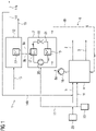
- FIG 1 shows an exemplary embodiment of an exemplary arrangement 1 for the environmentally friendly production of hydrogen 2.
- the arrangement 1 has an electrolysis device 4, a coolant circuit 6, a high-temperature heat pump 7, a regenerative power generation device 10 and a water desalination device 12.
- a power storage 23, z. B. a rechargeable battery may be provided.
- the electrolysis device 4 is designed, for example, as a low-pressure proton exchange electrolysis device for the electrolysis of water 5 .
- the electrolytic device 4 is supplied with water 5 which is electrolytically converted.
- the hydrogen 2 produced can be used, for example, as an energy source and/or as a starting material for chemical reactions.
- the electrolysis device 4 is supplied with regenerative electrical energy 11 generated by the regenerative power generation device 10 and supplied to the electrolysis device 4 directly or indirectly after intermediate storage in the optionally available power storage device 23 .
- the regenerative power generation device 10 can be embodied, for example, as a wind power plant or solar power plant. A combination of both technologies is also possible.
- the cooling medium circuit 6 is used, which is designed as a cooling water circuit in the exemplary embodiment, i. H. water is used as the cooling medium 8a, 8b.
- the cooling medium circuit 6 includes pipelines for receiving the cooling medium 8a, 8b.
- a pumping device 16 is arranged in the cooling medium circuit 6 and is used to form a flow of the cooling medium 8a, 8b in the pipelines of the cooling medium circuit 6 .
- the exemplary embodiment shown is the pumping device 16 downstream of the electrolysis device 7 and upstream of the high-temperature heat pump 7, but another positioning of the pumping device 16 in the coolant circuit 6 is also possible, for example directly upstream of the electrolysis device 4.
- cooling medium 8b with a low temperature e.g. B. about 35 ° C
- the cooling medium 8a with a high temperature flows into the high-temperature heat pump 7 after leaving the electrolysis device 4.
- the high-temperature heat pump 7 is also in a thermal Active connection with the cooling medium circuit 6.
- the cooling medium 8a In the high-temperature heat pump 7, heat is absorbed by the cooling medium 8a, so that this returns to the low temperature, ie z. B. about 35 ° C, cools.
- the cooling medium 8b can then be used again at a low temperature to cool the electrolysis device 4 .
- the high-temperature heat pump 7 is designed to absorb thermal energy from the cooling medium 8a, 8b (heat source) and to deliver it to a heating medium 9a, 9b (heat sink).
- a working medium 21 is used, which is circulated and in the process passes through various states of pressure, temperature and aggregate.
- the working medium 21 used in the exemplary embodiment is a synthetic refrigerant, e.g. B. so-called HCFOs (hydro-chloro-fluoro-olefins), or natural refrigerants.
- the initially liquid working medium 21 absorbs heat energy from the high-temperature cooling medium 8a in an evaporator 19 .
- the working medium 21 heats up and evaporates, i. H. it goes into the gaseous state of aggregation.
- the gaseous working medium 21 then enters the compressor 20, in which it is compressed.
- the working medium 21 is heated by this compression.
- the heated working medium 21 flows into the condenser 17.
- thermal energy is transferred from the working medium 21 to the heating medium 9a, 9b, as a result of which the working medium 21 cools down and returns to the liquid state.
- the pressure of the liquid working medium 21 is now reduced again as it flows through the expansion valve 18, as a result of which its boiling temperature drops.
- the working medium 21 can now again absorb thermal energy from the cooling medium 8a and evaporate it.
- Fresh water 14 is provided by means of the water desalination device 12 .
- the water desalination device 12 is saline water 13, z. B. sea water supplied.
- the salt contained in the saline water 13 is separated off by multi-stage flash evaporation.
- the resulting vapor 15 and the fresh water 14 leave the water desalination device 12.
- the water desalination device 12 requires thermal energy for the evaporation.
- the heating medium 9a, 9b which is circulated, is used for this.
- the heating medium 9b of low temperature (dash-dotted line), e.g. B. about 80 ° C is heated by means of the high-temperature heat pump 7 as described above.
- the heating medium 9a of high temperature (broken line), e.g. B. approx. 120 ° C, flows into a heat exchanger 22 of the water desalination device 12, gives off thermal energy in this, which is used for evaporation, and then flows back into the high-temperature heat pump 7 as a low-temperature heating medium 9b.
- the fresh water 14 provided by the water desalination device 12 can be used to water plantations and/or fed into a drinking water network (fresh water 14a). At least part of the fresh water (fresh water 14b) can be supplied to the electrolysis device 4 so that hydrogen 2 can be produced electrolytically from it.
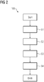
- hydrogen 2 is generated by electrolysis of water 5 in the first method step S1.
- the electrolysis of water produces 5 oxygen.
- a cooling medium 8b at a low temperature in the exemplary embodiment water at a temperature of approximately 35° C., is simultaneously heated in method step S2 by means of thermal energy emitted during the electrolysis.
- the cooling medium 8a, 8b flows in the cooling medium circuit 6.
- step S4 the heating medium 9a high temperature for desalination of saline water 13, z. B. sea water, used in the water desalination device 12.
- fresh water 14, 14a, 14b is provided in that saline water 13 is heated with the supply of energy by means of the heated heating medium 9a and is desalinated by separating off the salt by distillation.
- the fresh water 14, 14a, 14b provided in this way can optionally be at least partially supplied to the electrolysis device 4 and used as a reactant in the electrolysis for generating hydrogen 2.
- the method steps S1 to S4 are carried out at the same time.
- the term "and/or" when used in a series of two or more items means that each of the listed items can be used alone, or any combination of two or more of the listed items can be used.
Landscapes
- Engineering & Computer Science (AREA)
- Chemical & Material Sciences (AREA)
- Organic Chemistry (AREA)
- Electrochemistry (AREA)
- Materials Engineering (AREA)
- Metallurgy (AREA)
- Chemical Kinetics & Catalysis (AREA)
- Physics & Mathematics (AREA)
- Mechanical Engineering (AREA)
- Thermal Sciences (AREA)
- General Engineering & Computer Science (AREA)
- Automation & Control Theory (AREA)
- Inorganic Chemistry (AREA)
- Electrolytic Production Of Non-Metals, Compounds, Apparatuses Therefor (AREA)
Priority Applications (1)
| Application Number | Priority Date | Filing Date | Title |
|---|---|---|---|
| EP21175666.3A EP4095286A1 (fr) | 2021-05-25 | 2021-05-25 | Agencement et procédé de génération d'hydrogène respectueux de l'environnement |
Applications Claiming Priority (1)
| Application Number | Priority Date | Filing Date | Title |
|---|---|---|---|
| EP21175666.3A EP4095286A1 (fr) | 2021-05-25 | 2021-05-25 | Agencement et procédé de génération d'hydrogène respectueux de l'environnement |
Publications (1)
| Publication Number | Publication Date |
|---|---|
| EP4095286A1 true EP4095286A1 (fr) | 2022-11-30 |
Family
ID=76098851
Family Applications (1)
| Application Number | Title | Priority Date | Filing Date |
|---|---|---|---|
| EP21175666.3A Withdrawn EP4095286A1 (fr) | 2021-05-25 | 2021-05-25 | Agencement et procédé de génération d'hydrogène respectueux de l'environnement |
Country Status (1)
| Country | Link |
|---|---|
| EP (1) | EP4095286A1 (fr) |
Cited By (4)
| Publication number | Priority date | Publication date | Assignee | Title |
|---|---|---|---|---|
| CN117468021A (zh) * | 2023-11-09 | 2024-01-30 | 中国科学院大连化学物理研究所 | 一种碱性和质子交换膜混联海水制氢的系统及方法 |
| WO2024233038A1 (fr) * | 2023-05-09 | 2024-11-14 | Kraken Technology Holdings, LLC | Procédé d'utilisation de chaleur perdue et de dioxyde de carbone à partir de la production d'hydrogène d'intensité bas carbone, neutre en carbone et/ou négative en carbone provenant de l'électrolyse |
| WO2025080255A1 (fr) * | 2023-10-10 | 2025-04-17 | Acretio, Llc | Production intégrée d'hydrogène et d'eau douce utilisant une énergie renouvelable |
| EP4560223A1 (fr) * | 2023-11-21 | 2025-05-28 | SMS Concast AG | Dispositif et procédé de récupération d'énergie dans une installation de coulée continue |
Citations (6)
| Publication number | Priority date | Publication date | Assignee | Title |
|---|---|---|---|---|
| WO2012142996A2 (fr) * | 2011-04-19 | 2012-10-26 | Werner Dietrich Karl | Traitement de l'eau pour électrolyse de l'eau |
| DE102011086476A1 (de) | 2011-09-30 | 2013-04-04 | Siemens Aktiengesellschaft | Hochtemperaturwärmepumpe und Verfahren zur Verwendung eines Arbeitsmediums in einer Hochtemperaturwärmepumpe |
| EP2623640A1 (fr) * | 2012-02-02 | 2013-08-07 | Siemens Aktiengesellschaft | Procédé de fonctionnement d'un électrolyseur et un tel électrolyseur |
| DE102017006509A1 (de) * | 2017-07-10 | 2019-01-10 | Wilfried Kolb | Energieversorgungssystem unter Ausnutzung von Wasserstoff |
| EP3489394A1 (fr) | 2017-11-24 | 2019-05-29 | Siemens Aktiengesellschaft | Électrolyseur pour électrolyse pem à basse pression |
| DE102019202439A1 (de) * | 2019-02-22 | 2020-08-27 | Siemens Aktiengesellschaft | Vorrichtung, Energiesystem und Verfahren mit einem Elektrolyseur |
-
2021
- 2021-05-25 EP EP21175666.3A patent/EP4095286A1/fr not_active Withdrawn
Patent Citations (6)
| Publication number | Priority date | Publication date | Assignee | Title |
|---|---|---|---|---|
| WO2012142996A2 (fr) * | 2011-04-19 | 2012-10-26 | Werner Dietrich Karl | Traitement de l'eau pour électrolyse de l'eau |
| DE102011086476A1 (de) | 2011-09-30 | 2013-04-04 | Siemens Aktiengesellschaft | Hochtemperaturwärmepumpe und Verfahren zur Verwendung eines Arbeitsmediums in einer Hochtemperaturwärmepumpe |
| EP2623640A1 (fr) * | 2012-02-02 | 2013-08-07 | Siemens Aktiengesellschaft | Procédé de fonctionnement d'un électrolyseur et un tel électrolyseur |
| DE102017006509A1 (de) * | 2017-07-10 | 2019-01-10 | Wilfried Kolb | Energieversorgungssystem unter Ausnutzung von Wasserstoff |
| EP3489394A1 (fr) | 2017-11-24 | 2019-05-29 | Siemens Aktiengesellschaft | Électrolyseur pour électrolyse pem à basse pression |
| DE102019202439A1 (de) * | 2019-02-22 | 2020-08-27 | Siemens Aktiengesellschaft | Vorrichtung, Energiesystem und Verfahren mit einem Elektrolyseur |
Cited By (4)
| Publication number | Priority date | Publication date | Assignee | Title |
|---|---|---|---|---|
| WO2024233038A1 (fr) * | 2023-05-09 | 2024-11-14 | Kraken Technology Holdings, LLC | Procédé d'utilisation de chaleur perdue et de dioxyde de carbone à partir de la production d'hydrogène d'intensité bas carbone, neutre en carbone et/ou négative en carbone provenant de l'électrolyse |
| WO2025080255A1 (fr) * | 2023-10-10 | 2025-04-17 | Acretio, Llc | Production intégrée d'hydrogène et d'eau douce utilisant une énergie renouvelable |
| CN117468021A (zh) * | 2023-11-09 | 2024-01-30 | 中国科学院大连化学物理研究所 | 一种碱性和质子交换膜混联海水制氢的系统及方法 |
| EP4560223A1 (fr) * | 2023-11-21 | 2025-05-28 | SMS Concast AG | Dispositif et procédé de récupération d'énergie dans une installation de coulée continue |
Similar Documents
| Publication | Publication Date | Title |
|---|---|---|
| DE10061687B4 (de) | Verfahren zum Schutz einer Festpolymerelektrolyt-Brennstoffzelle vor Gefrierschäden | |
| DE19857398B4 (de) | Brennstoffzellensystem, insbesondere für elektromotorisch angetriebene Fahrzeuge | |
| EP4067533B1 (fr) | Procédé et installation de production électrolytique d'hydrogène liquide | |
| DE69902946T2 (de) | Brennstoffzellensystem mit verbesserter startfähigkeit | |
| DE102007026003B4 (de) | Brennstoffzellensystem mit verbesserten Kaltstarteigenschaften sowie Verfahren | |
| EP3384069A1 (fr) | Procédé et dispositif pour l'utilisation électrochimique de dioxyde de carbone | |
| EP3691989B1 (fr) | Appareil et procede de production d'hydrogene et son utilisation ulterieure | |
| DE102020005242A1 (de) | Wärmerückgewinnung bei Elektrolyseprozessen | |
| DE102011010113A1 (de) | Verfahren und Prozesse zum Rückgewinnen von Verlust elektrischer Spannung eines PEM-Brennstoffzellenstapels | |
| WO2023006724A2 (fr) | Cellule électrolytique à dispositif de thermorégulation, empilement d'électrolyseurs comportant un dispositif de thermorégulation, système d'électrolyse comportant l'empilement d'électrolyseurs et procédé de thermorégulation d'un empilement d'électrolyseurs | |
| EP3489394A1 (fr) | Électrolyseur pour électrolyse pem à basse pression | |
| EP2936598A1 (fr) | Procédé pour faire fonctionner un système de pile à combustible | |
| WO2024068048A2 (fr) | Procédé et installation permettant la préparation d'un produit contenant de l'hydrogène en ayant recours à une électrolyse | |
| EP3572557A1 (fr) | Dispositif d'électrolyse et procédé de fonctionnement du dispositif d'électrolyse | |
| DE102009048455A1 (de) | Verfahren und Vorrichtung zur Speicherung elektrischer Energie | |
| EP2907187A1 (fr) | Système de piles à combustible à base de piles à combustible à oxyde solide | |
| WO2020156734A1 (fr) | Procédé de fabrication de co à bon rendement énergétique | |
| DE102017000199A1 (de) | Verfahren und System zur Erzeugung von Wärme, Strom und Wasserstoff mit einer reversiblen Brennstoffzelle und einem Wasserstoffspeicher | |
| DE102020113105A1 (de) | Verfahren zum Ausschalten einer Brennstoffzellenvorrichtung | |
| DE19958179A1 (de) | Verdampfer für ein Brennstoffzellensystem | |
| EP4479578A2 (fr) | Procédé pour faire fonctionner une installation d'électrolyse et installation d'électrolyse | |
| EP4127269B1 (fr) | Procédé et dispositif de synthèse d'ammoniac | |
| DE102015201802B4 (de) | Wasserstofferzeugungsvorrichtung, Brennstoffzellensystem und Verfahren zum Erzeugen von Wasserstoff | |
| EP1233467A2 (fr) | Procédé et dispositif pour le refroidissement et le préchauffage mutuels des transducteurs électrochimiques couplés | |
| DE102006057198A1 (de) | Verfahren zur Temperierung einer Brennstoffzelle und eine Brennstoffzelle mit einer Temperiereinrichtung |
Legal Events
| Date | Code | Title | Description |
|---|---|---|---|
| PUAI | Public reference made under article 153(3) epc to a published international application that has entered the european phase |
Free format text: ORIGINAL CODE: 0009012 |
|
| STAA | Information on the status of an ep patent application or granted ep patent |
Free format text: STATUS: THE APPLICATION HAS BEEN PUBLISHED |
|
| AK | Designated contracting states |
Kind code of ref document: A1 Designated state(s): AL AT BE BG CH CY CZ DE DK EE ES FI FR GB GR HR HU IE IS IT LI LT LU LV MC MK MT NL NO PL PT RO RS SE SI SK SM TR |
|
| STAA | Information on the status of an ep patent application or granted ep patent |
Free format text: STATUS: THE APPLICATION IS DEEMED TO BE WITHDRAWN |
|
| 18D | Application deemed to be withdrawn |
Effective date: 20230531 |