EP4095421A1 - Schwenkklappenanordnung - Google Patents
Schwenkklappenanordnung Download PDFInfo
- Publication number
- EP4095421A1 EP4095421A1 EP22173401.5A EP22173401A EP4095421A1 EP 4095421 A1 EP4095421 A1 EP 4095421A1 EP 22173401 A EP22173401 A EP 22173401A EP 4095421 A1 EP4095421 A1 EP 4095421A1
- Authority
- EP
- European Patent Office
- Prior art keywords
- ring
- surrounding
- damper assembly
- abutment ring
- flow channel
- Prior art date
- Legal status (The legal status is an assumption and is not a legal conclusion. Google has not performed a legal analysis and makes no representation as to the accuracy of the status listed.)
- Granted
Links
Images

Classifications
-
- F—MECHANICAL ENGINEERING; LIGHTING; HEATING; WEAPONS; BLASTING
- F16—ENGINEERING ELEMENTS AND UNITS; GENERAL MEASURES FOR PRODUCING AND MAINTAINING EFFECTIVE FUNCTIONING OF MACHINES OR INSTALLATIONS; THERMAL INSULATION IN GENERAL
- F16K—VALVES; TAPS; COCKS; ACTUATING-FLOATS; DEVICES FOR VENTING OR AERATING
- F16K1/00—Lift valves or globe valves, i.e. cut-off apparatus with closure members having at least a component of their opening and closing motion perpendicular to the closing faces
- F16K1/16—Lift valves or globe valves, i.e. cut-off apparatus with closure members having at least a component of their opening and closing motion perpendicular to the closing faces with pivoted closure-members
- F16K1/18—Lift valves or globe valves, i.e. cut-off apparatus with closure members having at least a component of their opening and closing motion perpendicular to the closing faces with pivoted closure-members with pivoted discs or flaps
- F16K1/20—Lift valves or globe valves, i.e. cut-off apparatus with closure members having at least a component of their opening and closing motion perpendicular to the closing faces with pivoted closure-members with pivoted discs or flaps with axis of rotation arranged externally of valve member
- F16K1/2007—Lift valves or globe valves, i.e. cut-off apparatus with closure members having at least a component of their opening and closing motion perpendicular to the closing faces with pivoted closure-members with pivoted discs or flaps with axis of rotation arranged externally of valve member specially adapted operating means therefor
-
- F—MECHANICAL ENGINEERING; LIGHTING; HEATING; WEAPONS; BLASTING
- F16—ENGINEERING ELEMENTS AND UNITS; GENERAL MEASURES FOR PRODUCING AND MAINTAINING EFFECTIVE FUNCTIONING OF MACHINES OR INSTALLATIONS; THERMAL INSULATION IN GENERAL
- F16K—VALVES; TAPS; COCKS; ACTUATING-FLOATS; DEVICES FOR VENTING OR AERATING
- F16K1/00—Lift valves or globe valves, i.e. cut-off apparatus with closure members having at least a component of their opening and closing motion perpendicular to the closing faces
- F16K1/16—Lift valves or globe valves, i.e. cut-off apparatus with closure members having at least a component of their opening and closing motion perpendicular to the closing faces with pivoted closure-members
- F16K1/18—Lift valves or globe valves, i.e. cut-off apparatus with closure members having at least a component of their opening and closing motion perpendicular to the closing faces with pivoted closure-members with pivoted discs or flaps
- F16K1/20—Lift valves or globe valves, i.e. cut-off apparatus with closure members having at least a component of their opening and closing motion perpendicular to the closing faces with pivoted closure-members with pivoted discs or flaps with axis of rotation arranged externally of valve member
- F16K1/2042—Special features or arrangements of the sealing
- F16K1/205—Special features or arrangements of the sealing the sealing being arranged on the valve member
-
- F—MECHANICAL ENGINEERING; LIGHTING; HEATING; WEAPONS; BLASTING
- F16—ENGINEERING ELEMENTS AND UNITS; GENERAL MEASURES FOR PRODUCING AND MAINTAINING EFFECTIVE FUNCTIONING OF MACHINES OR INSTALLATIONS; THERMAL INSULATION IN GENERAL
- F16K—VALVES; TAPS; COCKS; ACTUATING-FLOATS; DEVICES FOR VENTING OR AERATING
- F16K1/00—Lift valves or globe valves, i.e. cut-off apparatus with closure members having at least a component of their opening and closing motion perpendicular to the closing faces
- F16K1/16—Lift valves or globe valves, i.e. cut-off apparatus with closure members having at least a component of their opening and closing motion perpendicular to the closing faces with pivoted closure-members
- F16K1/18—Lift valves or globe valves, i.e. cut-off apparatus with closure members having at least a component of their opening and closing motion perpendicular to the closing faces with pivoted closure-members with pivoted discs or flaps
- F16K1/20—Lift valves or globe valves, i.e. cut-off apparatus with closure members having at least a component of their opening and closing motion perpendicular to the closing faces with pivoted closure-members with pivoted discs or flaps with axis of rotation arranged externally of valve member
- F16K1/2042—Special features or arrangements of the sealing
- F16K1/2057—Special features or arrangements of the sealing the sealing being arranged on the valve seat
-
- F—MECHANICAL ENGINEERING; LIGHTING; HEATING; WEAPONS; BLASTING
- F16—ENGINEERING ELEMENTS AND UNITS; GENERAL MEASURES FOR PRODUCING AND MAINTAINING EFFECTIVE FUNCTIONING OF MACHINES OR INSTALLATIONS; THERMAL INSULATION IN GENERAL
- F16K—VALVES; TAPS; COCKS; ACTUATING-FLOATS; DEVICES FOR VENTING OR AERATING
- F16K1/00—Lift valves or globe valves, i.e. cut-off apparatus with closure members having at least a component of their opening and closing motion perpendicular to the closing faces
- F16K1/16—Lift valves or globe valves, i.e. cut-off apparatus with closure members having at least a component of their opening and closing motion perpendicular to the closing faces with pivoted closure-members
- F16K1/18—Lift valves or globe valves, i.e. cut-off apparatus with closure members having at least a component of their opening and closing motion perpendicular to the closing faces with pivoted closure-members with pivoted discs or flaps
- F16K1/22—Lift valves or globe valves, i.e. cut-off apparatus with closure members having at least a component of their opening and closing motion perpendicular to the closing faces with pivoted closure-members with pivoted discs or flaps with axis of rotation crossing the valve member, e.g. butterfly valves
- F16K1/226—Shaping or arrangements of the sealing
-
- F—MECHANICAL ENGINEERING; LIGHTING; HEATING; WEAPONS; BLASTING
- F23—COMBUSTION APPARATUS; COMBUSTION PROCESSES
- F23L—SUPPLYING AIR OR NON-COMBUSTIBLE LIQUIDS OR GASES TO COMBUSTION APPARATUS IN GENERAL ; VALVES OR DAMPERS SPECIALLY ADAPTED FOR CONTROLLING AIR SUPPLY OR DRAUGHT IN COMBUSTION APPARATUS; INDUCING DRAUGHT IN COMBUSTION APPARATUS; TOPS FOR CHIMNEYS OR VENTILATING SHAFTS; TERMINALS FOR FLUES
- F23L11/00—Arrangements of valves or dampers after the fire
-
- F—MECHANICAL ENGINEERING; LIGHTING; HEATING; WEAPONS; BLASTING
- F23—COMBUSTION APPARATUS; COMBUSTION PROCESSES
- F23L—SUPPLYING AIR OR NON-COMBUSTIBLE LIQUIDS OR GASES TO COMBUSTION APPARATUS IN GENERAL ; VALVES OR DAMPERS SPECIALLY ADAPTED FOR CONTROLLING AIR SUPPLY OR DRAUGHT IN COMBUSTION APPARATUS; INDUCING DRAUGHT IN COMBUSTION APPARATUS; TOPS FOR CHIMNEYS OR VENTILATING SHAFTS; TERMINALS FOR FLUES
- F23L13/00—Construction of valves or dampers for controlling air supply or draught
- F23L13/02—Construction of valves or dampers for controlling air supply or draught pivoted about a single axis but having not other movement
Definitions
- the invention relates to damper assembly as defined in the preamble of independent claim 1.
- the damper is especially, but not excluding other applications, suitable for use in industrial applications, power plants or the like.
- the damper assembly can be configured to in a closed position of a closure member of the damper assembly to isolate a section of a process arrangement downstream of the damper assembly from the process arrangement upstream of the damper assembly.
- To isolate can for example mean in this context that process gas, flue gas, particles, gas, and/or the like is prevented from passing the damper assembly in the process arrangement. This allows for example to perform maintenance actions on process equipment downstream of the damper assembly.
- the object of the invention is to provide a damper assembly that is suitable for use in environments where a high temperature and a high dust content such as a temperature up to 500°C and/or dust over 100 mg/Nm3 prevails.
- the damper assembly of the invention is characterized by the definitions of independent claim 1.
- damper assembly and some embodiments and variants of the damper assembly will be described in greater detail.
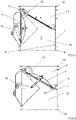
- the damper assembly comprising a casing 1 having an inner surface 2 defining a flow channel 3.
- Flanges 18 can be provided the end of the casing 1 to facilitate connecting of the damper assembly to ducting (not illustrated in the figures).
- the damper assembly comprising a closure member 4 mounted for pivotal movement about a pivot axis 5 in and out of the flow channel between a closed position in which it closes the flow channel 3 and an open position.
- the damper assembly comprising a sealing arrangement 6 for sealing the flow channel 3 in the closed position of the closure member 4.
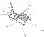
- the sealing arrangement 6 comprises a first ring member 7 of metal provided at the inner surface 2 of the casing 1 so as to prevent flow of fluid between the first ring member 7 and the inner surface 2 of the casing 1.
- the sealing arrangement 6 comprises a first surrounding abutment ring 8 of metal provided at the first ring member 7 of metal.
- the sealing arrangement 6 comprises a second surrounding abutment ring 9 of metal provided at the closure member 4 so as to prevent flow of fluid between the second surrounding abutment ring 9 and the closure member 4.
- the first surrounding abutment ring 8 and the second surrounding abutment ring 9 are configured to abut each other in the closed position of the closure member 4.
- the sealing arrangement 6 comprises a second ring member 10 of metal provided at the second surrounding abutment ring 9.
- the second ring member 10 and the first surrounding abutment ring 8 are configured to abut each other in the closed position of the closure member 4 so form a surrounding gas space 11 that is defined by the first surrounding abutment ring 8, the second surrounding abutment ring 9 and the second ring member 10.
- the sealing arrangement 6 comprises gas feeding means 12 configured to feed pressurized gas into the surrounding gas space 11.
- the damper assembly is suitable for use in environments where a high temperature such as a temperature up to 500°C and/or high dust content prevails. Because of the surrounding gas space 11 and because of the gas feeding means 12 configured to feed pressurized gas into the surrounding gas space 11, a sufficient sealing action will be provided.
- the damper assembly defines preferably, but not necessarily, as in the embodiment of the damper assembly illustrated in the figures, and as shown in figure 4 in the closed position of the closure member 4 an upstream part 16 of the flow channel 3 and a downstream part 17 of the flow channel 3, so that the upstream part 16 of the flow channel 3 is separated from the downstream part 17 of the flow channel 3 by means of the closure member 4 and the sealing arrangement 6.
- the gas feeding means 12 is preferably, but not necessarily, configured to feed pressurized gas into the surrounding gas space 11 having a pressure that is at least the pressure in the upstream part 16 of the flow channel 3. This to prevent fluid flow from the upstream part 16 of the flow channel 3 to the downstream part 17 of the flow channel 3 via/through the surrounding gas space 11.
- the closure member 4 can, as illustrated in the figures, be pivotably attached to the first ring member 7 by means of at least one arm member 13.
- the closure member 4 can, as illustrated in the figures, be pivotably attached at the inner surface 2 of the casing 1 by means of a linkage arrangement 14 provided between the closure member 4 and the inner surface 2 of the casing 1.
- a drive means 15 can be functionally connected to the linkage arrangement 14 to effect pivotal movement of the closure between the closed position and the open position.
- the flow channel 3 is preferably, but not necessarily, essentially unobstructed by the closure member 4, the second ring member 10 and the second surrounding abutment ring 9 in the open position of the closure member 4.
- the flow channel 3 has preferably, but not necessarily, a circular cross-section in a direction of flow through the damper assembly.
- the pivot axis 5 can, as illustrated in the figures, be provided eccentrically with respect to said circular cross-section.
- the first surrounding abutment ring 8 of metal and the first ring member 7 of metal can, as illustrated in the figures, be provided in an angle with respect to the direction of flow through the damper assembly
- the first surrounding abutment ring 8 of metal is preferably, but not necessarily, made of steel.
- the second surrounding abutment ring 9 of metal is preferably, but not necessarily, made of steel.
- the first ring member 7 of metal is preferably, but not necessarily, made of steel.
- the second ring member 10 of metal is preferably, but not necessarily, made of steel, preferably of stainless steel.
- the gas feeding means 12 is preferably, but not necessarily, configured to feed pressurized gas into the surrounding gas space 11 through openings extending through the first ring member 7 of metal and through the first surrounding abutment ring 8 of metal.
- the damper assembly defines preferably, but not necessarily, as in the embodiment of the damper assembly illustrated in the figures, in the closed position of the closure member 4 an upstream part 16 of the flow channel 3 and a downstream part 17 of the flow channel 3, so that the upstream part 16 of the flow channel 3 is separated from the downstream part 17 of the flow channel 3 by means of the closure member 4 and the sealing arrangement 6.
- the second ring member 10 of the sealing arrangement 6 is preferably, but not necessarily, provided to face the upstream part 16 of the flow channel 3 in the closed position of the closure member 4.
- the first surrounding abutment ring 8 and the second surrounding abutment ring 9 are preferably, but not necessarily, configured to abut each other in the closed position of the closure member 4 so as to allow pressurized gas to pass to the downstream part 17 of the flow channel 3 from the surrounding gas space 11 that is defined by the first surrounding abutment ring 8, the second surrounding abutment ring 9 and the second ring member 10 and/or so as to allow pressurized gas to pass to the upstream part 16 of the flow channel 3 from the surrounding gas space 11 that is defined by the first surrounding abutment ring 8, the second surrounding abutment ring 9 and the second ring member 10.
- the second ring member 10 is preferably, but not necessarily, configured to elastically deform in the closed position of the closure member 4.
- a sealing means 20 is preferably, but not necessarily, provided between the first ring member 7 and the first surrounding abutment ring 8.
- the sealing means 20 can for example comprise fiberglass, graphite or the like.
- the first ring member 7 is preferably, but not necessarily, fastened to the first surrounding abutment ring 8 by means of bolts 19, screws, or the like.
- the second ring member 10 is preferably, but not necessarily, fastened to the second surrounding abutment ring 9 by means of bolts 19, screws or the like.
Landscapes
- Engineering & Computer Science (AREA)
- General Engineering & Computer Science (AREA)
- Mechanical Engineering (AREA)
- Chemical & Material Sciences (AREA)
- Combustion & Propulsion (AREA)
- Lift Valve (AREA)
- Fluid-Damping Devices (AREA)
Applications Claiming Priority (1)
| Application Number | Priority Date | Filing Date | Title |
|---|---|---|---|
| FI20215628A FI130133B (fi) | 2021-05-28 | 2021-05-28 | Peltijärjestely |
Publications (3)
| Publication Number | Publication Date |
|---|---|
| EP4095421A1 true EP4095421A1 (de) | 2022-11-30 |
| EP4095421C0 EP4095421C0 (de) | 2023-10-11 |
| EP4095421B1 EP4095421B1 (de) | 2023-10-11 |
Family
ID=81655062
Family Applications (1)
| Application Number | Title | Priority Date | Filing Date |
|---|---|---|---|
| EP22173401.5A Active EP4095421B1 (de) | 2021-05-28 | 2022-05-16 | Schwenkklappenanordnung |
Country Status (2)
| Country | Link |
|---|---|
| EP (1) | EP4095421B1 (de) |
| FI (1) | FI130133B (de) |
Citations (3)
| Publication number | Priority date | Publication date | Assignee | Title |
|---|---|---|---|---|
| US4821507A (en) * | 1987-05-29 | 1989-04-18 | Bachmann Industries, Inc. | Gas flow diverter |
| AT1262U1 (de) * | 1994-10-06 | 1997-01-27 | Sammet Dekomte Oy | Sperrklappe |
| EP0843129A2 (de) * | 1996-11-19 | 1998-05-20 | Sammet Dampers Oy | Schliessklappe eines Kanals |
-
2021
- 2021-05-28 FI FI20215628A patent/FI130133B/fi active
-
2022
- 2022-05-16 EP EP22173401.5A patent/EP4095421B1/de active Active
Patent Citations (3)
| Publication number | Priority date | Publication date | Assignee | Title |
|---|---|---|---|---|
| US4821507A (en) * | 1987-05-29 | 1989-04-18 | Bachmann Industries, Inc. | Gas flow diverter |
| AT1262U1 (de) * | 1994-10-06 | 1997-01-27 | Sammet Dekomte Oy | Sperrklappe |
| EP0843129A2 (de) * | 1996-11-19 | 1998-05-20 | Sammet Dampers Oy | Schliessklappe eines Kanals |
Also Published As
| Publication number | Publication date |
|---|---|
| FI130133B (fi) | 2023-03-09 |
| EP4095421C0 (de) | 2023-10-11 |
| EP4095421B1 (de) | 2023-10-11 |
| FI20215628A1 (en) | 2022-11-29 |
Similar Documents
| Publication | Publication Date | Title |
|---|---|---|
| CN101910698B (zh) | 用于具有两件式阀笼的阀的密封组件 | |
| AU2010254429B2 (en) | Valve trim apparatus for use with valves | |
| EP2140180B1 (de) | Kugelventil mit entfernbarem mittel zum festhalten der axialdichtung | |
| KR102024951B1 (ko) | 압력-평형 유압 조절기 | |
| EP0838617A1 (de) | Ventileinheit | |
| US9791067B2 (en) | Flare tip valve dampening | |
| US20100150544A1 (en) | Iris damper | |
| US11236845B2 (en) | Valve trim apparatus having multiple fluid flow control members | |
| EP4165330B1 (de) | Ventil und verfahren zur reinigung eines ventils | |
| US10077850B2 (en) | Reverse taper piston for pneumatic actuators | |
| US12140239B2 (en) | Fluid flow device | |
| US20130168591A1 (en) | Valve seat, valve with seat and method of fitting seat to valve | |
| EP4095421A1 (de) | Schwenkklappenanordnung | |
| US7780143B2 (en) | Gate valve | |
| US6969044B2 (en) | Apparatus for controlling a fluid discharge | |
| US8814138B2 (en) | Valve seals | |
| CN211496032U (zh) | 负压管道泄压装置及烟草加工系统 | |
| US4484562A (en) | Flexible disk damper | |
| US4338960A (en) | Guillotine type damper | |
| CN220581763U (zh) | 一种通风阀 | |
| KR102550352B1 (ko) | 다축모션 구조의 버터플라이 댐퍼 | |
| CN223923849U (zh) | 高温烟气蝶阀 | |
| KR102585015B1 (ko) | 스크러버 계통의 더블 디스크 밸브 | |
| EP4090867B1 (de) | Fluidstromvorrichtung | |
| EP0843129B1 (de) | Schliessklappe eines Kanals |
Legal Events
| Date | Code | Title | Description |
|---|---|---|---|
| PUAI | Public reference made under article 153(3) epc to a published international application that has entered the european phase |
Free format text: ORIGINAL CODE: 0009012 |
|
| STAA | Information on the status of an ep patent application or granted ep patent |
Free format text: STATUS: REQUEST FOR EXAMINATION WAS MADE |
|
| 17P | Request for examination filed |
Effective date: 20220516 |
|
| AK | Designated contracting states |
Kind code of ref document: A1 Designated state(s): AL AT BE BG CH CY CZ DE DK EE ES FI FR GB GR HR HU IE IS IT LI LT LU LV MC MK MT NL NO PL PT RO RS SE SI SK SM TR |
|
| GRAP | Despatch of communication of intention to grant a patent |
Free format text: ORIGINAL CODE: EPIDOSNIGR1 |
|
| STAA | Information on the status of an ep patent application or granted ep patent |
Free format text: STATUS: GRANT OF PATENT IS INTENDED |
|
| INTG | Intention to grant announced |
Effective date: 20230614 |
|
| GRAS | Grant fee paid |
Free format text: ORIGINAL CODE: EPIDOSNIGR3 |
|
| GRAA | (expected) grant |
Free format text: ORIGINAL CODE: 0009210 |
|
| STAA | Information on the status of an ep patent application or granted ep patent |
Free format text: STATUS: THE PATENT HAS BEEN GRANTED |
|
| AK | Designated contracting states |
Kind code of ref document: B1 Designated state(s): AL AT BE BG CH CY CZ DE DK EE ES FI FR GB GR HR HU IE IS IT LI LT LU LV MC MK MT NL NO PL PT RO RS SE SI SK SM TR |
|
| REG | Reference to a national code |
Ref country code: GB Ref legal event code: FG4D |
|
| REG | Reference to a national code |
Ref country code: CH Ref legal event code: EP |
|
| REG | Reference to a national code |
Ref country code: DE Ref legal event code: R096 Ref document number: 602022000660 Country of ref document: DE |
|
| REG | Reference to a national code |
Ref country code: IE Ref legal event code: FG4D |
|
| U01 | Request for unitary effect filed |
Effective date: 20231109 |
|
| U07 | Unitary effect registered |
Designated state(s): AT BE BG DE DK EE FI FR IT LT LU LV MT NL PT SE SI Effective date: 20231116 |
|
| PG25 | Lapsed in a contracting state [announced via postgrant information from national office to epo] |
Ref country code: GR Free format text: LAPSE BECAUSE OF FAILURE TO SUBMIT A TRANSLATION OF THE DESCRIPTION OR TO PAY THE FEE WITHIN THE PRESCRIBED TIME-LIMIT Effective date: 20240112 |
|
| PG25 | Lapsed in a contracting state [announced via postgrant information from national office to epo] |
Ref country code: IS Free format text: LAPSE BECAUSE OF FAILURE TO SUBMIT A TRANSLATION OF THE DESCRIPTION OR TO PAY THE FEE WITHIN THE PRESCRIBED TIME-LIMIT Effective date: 20240211 |
|
| PG25 | Lapsed in a contracting state [announced via postgrant information from national office to epo] |
Ref country code: ES Free format text: LAPSE BECAUSE OF FAILURE TO SUBMIT A TRANSLATION OF THE DESCRIPTION OR TO PAY THE FEE WITHIN THE PRESCRIBED TIME-LIMIT Effective date: 20231011 |
|
| PG25 | Lapsed in a contracting state [announced via postgrant information from national office to epo] |
Ref country code: IS Free format text: LAPSE BECAUSE OF FAILURE TO SUBMIT A TRANSLATION OF THE DESCRIPTION OR TO PAY THE FEE WITHIN THE PRESCRIBED TIME-LIMIT Effective date: 20240211 Ref country code: GR Free format text: LAPSE BECAUSE OF FAILURE TO SUBMIT A TRANSLATION OF THE DESCRIPTION OR TO PAY THE FEE WITHIN THE PRESCRIBED TIME-LIMIT Effective date: 20240112 Ref country code: ES Free format text: LAPSE BECAUSE OF FAILURE TO SUBMIT A TRANSLATION OF THE DESCRIPTION OR TO PAY THE FEE WITHIN THE PRESCRIBED TIME-LIMIT Effective date: 20231011 |
|
| PG25 | Lapsed in a contracting state [announced via postgrant information from national office to epo] |
Ref country code: RS Free format text: LAPSE BECAUSE OF FAILURE TO SUBMIT A TRANSLATION OF THE DESCRIPTION OR TO PAY THE FEE WITHIN THE PRESCRIBED TIME-LIMIT Effective date: 20231011 Ref country code: PL Free format text: LAPSE BECAUSE OF FAILURE TO SUBMIT A TRANSLATION OF THE DESCRIPTION OR TO PAY THE FEE WITHIN THE PRESCRIBED TIME-LIMIT Effective date: 20231011 Ref country code: NO Free format text: LAPSE BECAUSE OF FAILURE TO SUBMIT A TRANSLATION OF THE DESCRIPTION OR TO PAY THE FEE WITHIN THE PRESCRIBED TIME-LIMIT Effective date: 20240111 Ref country code: HR Free format text: LAPSE BECAUSE OF FAILURE TO SUBMIT A TRANSLATION OF THE DESCRIPTION OR TO PAY THE FEE WITHIN THE PRESCRIBED TIME-LIMIT Effective date: 20231011 |
|
| U20 | Renewal fee for the european patent with unitary effect paid |
Year of fee payment: 3 Effective date: 20240527 |
|
| REG | Reference to a national code |
Ref country code: DE Ref legal event code: R097 Ref document number: 602022000660 Country of ref document: DE |
|
| PG25 | Lapsed in a contracting state [announced via postgrant information from national office to epo] |
Ref country code: CZ Free format text: LAPSE BECAUSE OF FAILURE TO SUBMIT A TRANSLATION OF THE DESCRIPTION OR TO PAY THE FEE WITHIN THE PRESCRIBED TIME-LIMIT Effective date: 20231011 |
|
| PG25 | Lapsed in a contracting state [announced via postgrant information from national office to epo] |
Ref country code: SK Free format text: LAPSE BECAUSE OF FAILURE TO SUBMIT A TRANSLATION OF THE DESCRIPTION OR TO PAY THE FEE WITHIN THE PRESCRIBED TIME-LIMIT Effective date: 20231011 |
|
| PG25 | Lapsed in a contracting state [announced via postgrant information from national office to epo] |
Ref country code: SM Free format text: LAPSE BECAUSE OF FAILURE TO SUBMIT A TRANSLATION OF THE DESCRIPTION OR TO PAY THE FEE WITHIN THE PRESCRIBED TIME-LIMIT Effective date: 20231011 Ref country code: SK Free format text: LAPSE BECAUSE OF FAILURE TO SUBMIT A TRANSLATION OF THE DESCRIPTION OR TO PAY THE FEE WITHIN THE PRESCRIBED TIME-LIMIT Effective date: 20231011 Ref country code: RO Free format text: LAPSE BECAUSE OF FAILURE TO SUBMIT A TRANSLATION OF THE DESCRIPTION OR TO PAY THE FEE WITHIN THE PRESCRIBED TIME-LIMIT Effective date: 20231011 Ref country code: CZ Free format text: LAPSE BECAUSE OF FAILURE TO SUBMIT A TRANSLATION OF THE DESCRIPTION OR TO PAY THE FEE WITHIN THE PRESCRIBED TIME-LIMIT Effective date: 20231011 |
|
| PLBE | No opposition filed within time limit |
Free format text: ORIGINAL CODE: 0009261 |
|
| STAA | Information on the status of an ep patent application or granted ep patent |
Free format text: STATUS: NO OPPOSITION FILED WITHIN TIME LIMIT |
|
| 26N | No opposition filed |
Effective date: 20240712 |
|
| PG25 | Lapsed in a contracting state [announced via postgrant information from national office to epo] |
Ref country code: MC Free format text: LAPSE BECAUSE OF FAILURE TO SUBMIT A TRANSLATION OF THE DESCRIPTION OR TO PAY THE FEE WITHIN THE PRESCRIBED TIME-LIMIT Effective date: 20231011 |
|
| PG25 | Lapsed in a contracting state [announced via postgrant information from national office to epo] |
Ref country code: MC Free format text: LAPSE BECAUSE OF FAILURE TO SUBMIT A TRANSLATION OF THE DESCRIPTION OR TO PAY THE FEE WITHIN THE PRESCRIBED TIME-LIMIT Effective date: 20231011 |
|
| PG25 | Lapsed in a contracting state [announced via postgrant information from national office to epo] |
Ref country code: IE Free format text: LAPSE BECAUSE OF NON-PAYMENT OF DUE FEES Effective date: 20240516 |
|
| U20 | Renewal fee for the european patent with unitary effect paid |
Year of fee payment: 4 Effective date: 20250528 |
|
| PG25 | Lapsed in a contracting state [announced via postgrant information from national office to epo] |
Ref country code: CY Free format text: LAPSE BECAUSE OF FAILURE TO SUBMIT A TRANSLATION OF THE DESCRIPTION OR TO PAY THE FEE WITHIN THE PRESCRIBED TIME-LIMIT; INVALID AB INITIO Effective date: 20220516 |
|
| PG25 | Lapsed in a contracting state [announced via postgrant information from national office to epo] |
Ref country code: HU Free format text: LAPSE BECAUSE OF FAILURE TO SUBMIT A TRANSLATION OF THE DESCRIPTION OR TO PAY THE FEE WITHIN THE PRESCRIBED TIME-LIMIT; INVALID AB INITIO Effective date: 20220516 |
|
| REG | Reference to a national code |
Ref country code: CH Ref legal event code: H13 Free format text: ST27 STATUS EVENT CODE: U-0-0-H10-H13 (AS PROVIDED BY THE NATIONAL OFFICE) Effective date: 20251223 |
|
| PG25 | Lapsed in a contracting state [announced via postgrant information from national office to epo] |
Ref country code: CH Free format text: LAPSE BECAUSE OF NON-PAYMENT OF DUE FEES Effective date: 20250531 |