EP4095501B1 - Dynamomètre hydraulique de grande capacité de type hydrodynamique doté d'un mécanisme de contrôle de sortie - Google Patents
Dynamomètre hydraulique de grande capacité de type hydrodynamique doté d'un mécanisme de contrôle de sortie Download PDFInfo
- Publication number
- EP4095501B1 EP4095501B1 EP22166704.1A EP22166704A EP4095501B1 EP 4095501 B1 EP4095501 B1 EP 4095501B1 EP 22166704 A EP22166704 A EP 22166704A EP 4095501 B1 EP4095501 B1 EP 4095501B1
- Authority
- EP
- European Patent Office
- Prior art keywords
- pair
- toroidal
- hydrodynamic
- chambers
- type hydraulic
- Prior art date
- Legal status (The legal status is an assumption and is not a legal conclusion. Google has not performed a legal analysis and makes no representation as to the accuracy of the status listed.)
- Active
Links
Images



Classifications
-
- G—PHYSICS
- G01—MEASURING; TESTING
- G01L—MEASURING FORCE, STRESS, TORQUE, WORK, MECHANICAL POWER, MECHANICAL EFFICIENCY, OR FLUID PRESSURE
- G01L1/00—Measuring force or stress, in general
- G01L1/02—Measuring force or stress, in general by hydraulic or pneumatic means
-
- G—PHYSICS
- G01—MEASURING; TESTING
- G01M—TESTING STATIC OR DYNAMIC BALANCE OF MACHINES OR STRUCTURES; TESTING OF STRUCTURES OR APPARATUS, NOT OTHERWISE PROVIDED FOR
- G01M15/00—Testing of engines
- G01M15/02—Details or accessories of testing apparatus
-
- G—PHYSICS
- G01—MEASURING; TESTING
- G01L—MEASURING FORCE, STRESS, TORQUE, WORK, MECHANICAL POWER, MECHANICAL EFFICIENCY, OR FLUID PRESSURE
- G01L3/00—Measuring torque, work, mechanical power, or mechanical efficiency, in general
- G01L3/16—Rotary-absorption dynamometers, e.g. of brake type
- G01L3/20—Rotary-absorption dynamometers, e.g. of brake type fluid actuated
-
- G—PHYSICS
- G01—MEASURING; TESTING
- G01L—MEASURING FORCE, STRESS, TORQUE, WORK, MECHANICAL POWER, MECHANICAL EFFICIENCY, OR FLUID PRESSURE
- G01L5/00—Apparatus for, or methods of, measuring force, work, mechanical power, or torque, specially adapted for specific purposes
- G01L5/13—Apparatus for, or methods of, measuring force, work, mechanical power, or torque, specially adapted for specific purposes for measuring the tractive or propulsive power of vehicles
Definitions
- Apparatuses and methods consistent with exemplary embodiments relate to a large-capacity hydrodynamic-type hydraulic dynamometer with output control mechanism, and more particularly, to a large-capacity hydrodynamic-type hydraulic dynamometer having a mechanism for controlling output of the hydraulic dynamometer by adjusting an amount of a recirculating working fluid.
- a high-power engine uses a hydraulic dynamometer using water, which is a device that absorbs engine power to measure the absorbed power for engine performance testing.
- dynamometers are used depending on the output and operating (i.e., rotational) speed of an engine.
- Dynamometers used in large-capacity and high-speed engines such as gas turbines may be classified into a friction-disk-type dynamometer called a Kahn type dynamometer and a hydrodynamic-type dynamometer called a Froude type dynamometer.
- a hydraulic dynamometer absorbs engine power transmitted to the dynamometer by hydraulic resistance between a rotor, a stator, and a housing.
- To control cavitation and load fluctuation is the key in the hydraulic dynamometer, which is mainly used for performance testing of large high-speed gas turbines having 100 MW or more and 3,000 rpm or more. That is, an additional increase in output and resolution of excessive load fluctuation are required in the hydrodynamic-type hydraulic dynamometer.
- the output of the gas turbine may be unstable at the 20% level thereof and the blade of the runner of the gas turbine may be damaged due to excessive fluctuation and cavitation.
- US 2 428 005 A discloses a dynamometer of the hydraulic turbine type with chambers in which fluid is circulated toroidally.
- a hydrodynamic-type hydraulic dynamometer according to independent claim 1. Further refinements and embodiments of the hydrodynamic-type hydraulic dynamometer are subject of the corresponding dependent claims. Aspects of one or more exemplary embodiments relate to a large-capacity hydrodynamic-type hydraulic dynamometer with output control mechanism, which is capable of controlling a flow rate of recirculating fluid by a shutter mechanism that adjusts a flow rate of fluid circulating in a toroidal chamber in order to solve output drop and uncontrollable phenomenon occurring in the large-capacity hydrodynamic-type hydraulic dynamometer such as in a load test of a large-capacity gas turbine.
- a hydrodynamic-type hydraulic dynamometer including: a shaft rotatably mounted by a plurality of bearings, a stator fixed around the shaft and having a toroidal chamber therein, a runner rotatably coupled to the shaft and causing a fluid introduced into the toroidal chamber to flow therethrough, an inner ring mounted to extend inwardly from a radially outer side of the toroidal chamber and having a control slit formed therethrough, and a shutter configured to adjust an opening degree of the control slit.
- the toroidal chamber may include a pair of toroidal chambers having bilateral symmetry, and the runner may include a plurality of blades exposed to an inside of each of the pair of toroidal chambers to circulate the fluid introduced into the toroidal chamber.
- the hydrodynamic-type hydraulic dynamometer may further include a guide ring disposed between the pair of toroidal chambers and having both sides forming a portion of inner peripheral surface of each toroidal chamber.
- the stator may further include a drain chamber formed radially outside the pair of toroidal chambers.
- the pair of toroidal chambers may further include a pair of drain slots formed on the radially outer sides thereof to communicate with the drain chamber between the pair of toroidal chambers and the guide ring.
- the stator may further include inlet chambers formed on each axial side of the pair of toroidal chambers.
- the pair of toroidal chambers may include a pair of fluid supply nozzles formed on radially inner sides thereof to communicate from the inlet chambers to the toroidal chambers.
- the toroidal chamber may have an elliptical cross-section.
- the hydrodynamic-type hydraulic dynamometer may further include an actuator mounted on an outer peripheral surface of the stator to move the shutter in a radial direction.
- the hydrodynamic-type hydraulic dynamometer may further include a displacement sensor provided on one side of the actuator to measure a displacement of the shutter.
- the hydrodynamic-type hydraulic dynamometer may further include a stopper provided radially inside the actuator to limit a maximum displacement of the actuator.
- the stator may have a pair of toroidal chambers therein.
- the runner may have a plurality of blades to circulate a fluid introduced into the pair of toroidal chambers.
- the inner ring may be provided as a pair of inner rings mounted to extend inwardly from radially outer sides of the pair of toroidal chambers and each having a control slit formed therethrough.
- the hydrodynamic-type hydraulic dynamometer may further comprise guide ring disposed between the pair of toroidal chambers and having both sides forming a portion of inner peripheral surface of each toroidal chamber.
- the shutter may be provided as a pair of shutters each configured to adjust an opening degree of a corresponding one of the control slits.
- the hydrodynamic-type hydraulic dynamometer may further include an actuator mounted on an outer peripheral surface of the stator to move a corresponding one of the shutters in a radial direction, and a stopper provided radially inside the actuator to limit a maximum displacement of the actuator.
- the hydrodynamic-type hydraulic dynamometer may further include a displacement sensor provided on one side of the actuator to measure a displacement of the corresponding shutter.
- the stator may further include a pair of inlet chambers formed on each axial side of the pair of toroidal chambers, and a drain chamber formed radially outside the pair of toroidal chambers.
- the pair of toroidal chambers may include a pair of fluid supply nozzles formed on radially inner sides thereof to communicate from the inlet chambers to the toroidal chambers.
- the pair of toroidal chambers may further include a pair of drain slots formed on the radially outer sides thereof to communicate with the drain chamber between the pair of toroidal chambers and the guide ring.
- the pair of inner rings each having the control slit and the shutter each may include a plurality of inner rings having a plurality of control slits and a plurality of shutters arranged circumferentially in the pair of toroidal chambers, and the plurality of shutters may adjust opening degree of some of the plurality of control slits arranged in upper halves of the toroidal chambers.
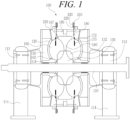
- FIG. 1 is a cross-sectional view illustrating a hydrodynamic-type hydraulic dynamometer according to an exemplary embodiment.
- FIG. 2 is a cross-sectional view illustrating an upper half of the hydrodynamic-type hydraulic dynamometer of FIG. 1 .
- FIG. 3 is a partial cross-sectional view illustrating a flow of fluid supplied through fluid supply nozzles, a flow of fluid recirculated to a toroidal chamber through a slit of an inner ring, and a flow of fluid discharged through a drain slot in the hydrodynamic-type hydraulic dynamometer of FIG. 2 .
- the hydrodynamic-type hydraulic dynamometer 100 may include a shaft 110 rotatably mounted by a plurality of bearings 112, a stator 120 fixed around the shaft 110 and having a toroidal chamber 160 therein, a runner 130 rotatably coupled to the shaft 110 and allowing a fluid introduced into the toroidal chamber 160 to flow therethrough, an inner ring 170 mounted to extend inwardly from a radially outer side of the toroidal chamber 160 and having a control slit 172 formed therethrough, and a shutter 180 configured to adjust an opening degree of the control slit 172.
- the shaft 110 may have one end coupled to a rotary shaft of a target to be measured.
- the shaft 110 may be rotatably mounted by a pair of bearings 112 coupled to both sides of the stator 120 by passing through the stator 120.
- Each of the pair of bearings 112 may be supported on the ground by a support 114.
- the stator 120 may have both sides connected to a casing for the pair of bearing 112 to be supported by a pair of supports 114.
- the stator 120 may have a shaft hole penetrating through the shaft 110 to be fixed around the shaft 110.
- the stator 120 may include the toroidal chamber 160 therein.
- the toroidal chamber 160 may be disposed around the shaft 110 to surround the shaft 110.
- the runner 130 may be rotatably coupled to the shaft 110 and may cause a fluid introduced into the toroidal chamber 160 to flow therethrough.
- the runner 130 is coupled to the shaft 110 and rotates together, and may form a portion of an inner peripheral surface of the toroidal chamber 160.
- the runner 130 may include a plurality of blades 132 exposed to an internal space of the toroidal chamber 160.
- the plurality of blades 132 may be formed integrally and arranged in a circumferential direction of the runner 130.
- the inner ring 170 is a flat plate in a form of a fan, and may be mounted to extend from the outside in the radial direction of the toroidal chamber 160 to the inside to prevent the flow of the fluid circulated in the toroidal chamber 160.
- the control slit 172 is formed to pass through the inner ring 170 and has an elongated shape in the circumferential direction, thereby enabling a fluid to be circulated through the control slit 172.
- the shutter 180 may be radially movably mounted on the stator 120 to adjust the opening degree of the control slit 172.
- the shutter 180 may include a plurality of shutters arranged in the circumferential direction outside the toroidal chamber 160 of the stator 120. As each shutter 180 moves further radially inward, the opening degree of the control slit 172 of the inner ring 170 may decrease.
- the toroidal chamber 160 may include a pair of toroidal chambers having bilateral symmetry. Each of the toroidal chambers 160 may have a circular or elliptical cross-section. When the toroidal chamber 160 has an elliptical cross-section, the fluid in the toroidal chamber 160 rotated by the shaft 110 and subjected to centrifugal force may flow smoothly in the circumferential direction while recirculating.
- a guide ring 140 may be disposed between the pair of toroidal chambers 160, and both side surfaces may form a part of the inner peripheral surface of each toroidal chamber 160.
- the guide ring 140 may have a radially inner surface forming about 90 degrees with the inner peripheral surfaces of the pair of toroidal chambers 160.
- the guide ring 140 may continue to extend in the circumferential direction or may be integrally formed.
- the guide ring 140 may have a radially inner end spaced apart from the radially outer end of the runner 130 by a predetermined distance. Thus, a portion of the fluid flowing in one of the pair of toroidal chambers 160 may be mixed with the fluid flowing in the other toroidal chamber of the pair of toroidal chambers 160.
- the stator 120 may further include inlet chambers 150 formed on each axial side surface of the pair of toroidal chambers 160.
- the pair of inlet chambers 150 serves to temporarily store the working fluid to be supplied to the pair of toroidal chambers 160.
- the pair of toroidal chambers 160 may include a pair of fluid supply nozzles 162 radially inside thereof to communicate from the inlet chambers 150 to the toroidal chambers 160.
- the pair of fluid supply nozzles 162 may be formed near the relatively radially inner ends of the pair of toroidal chambers 160 on the axial outer surfaces thereof.
- the pair of fluid supply nozzles 162 may be formed substantially parallel to the shaft 110. Accordingly, the fluid in the pair of inlet chambers 150 may be introduced into the pair of toroidal chambers 160 through the pair of fluid supply nozzles 162, and circulate in each of the toroidal chambers 160 by the blades 132 of the runner 130.
- the stator 120 may further include a drain chamber 190 formed radially outside the pair of toroidal chambers 160.
- the drain chamber 190 may be continuously circumferentially formed radially outside the pair of toroidal chambers 160 of the stator 120.
- the drain chamber 190 may be sealed by a cover coupled to the stator 120 outside a groove continuously formed on the outer peripheral surface of the stator 120.
- the drain chamber 190 may be partitioned by a pair of partitions outside the pair of toroidal chambers 160.
- the partitioned drain chambers 190 may have internal spaces that communicate with each other through communication holes formed through the partitions.
- the pair of toroidal chambers 160 may further include a pair of drain slots 167 formed on the outside in the radial direction to communicate with the drain chamber 190 between the pair of toroidal chambers 160 and the guide ring 140. That is, the pair of drain slots 167 may be formed with a predetermined size between both sides of the guide ring 140 in the axial direction and the stator 120. One drain slot 167 may be continuously formed along the circumference, or a plurality of drain slots 167 may be arranged at predetermined intervals.
- FIG. 1 illustrates the pair of toroidal chambers 160
- two or more pairs of toroidal chambers 160 may be disposed depending on the capacity of the hydraulic dynamometer.
- two or more pairs of toroidal chambers 160 two or more pairs of inlet chambers 150, inner rings 170, and shutters 180 may be provided, and two or more runners 130, guide rings 140, and drain chambers 190 may be provided.
- the stator 120 may include a seal member 118 configured to seal a gap between the stator 120 and the shaft 110 on an inner circumferential surface thereof.
- the seal member 118 may be made of an elastic material and may have a cross-section in a form of a plurality of wedges continuously formed along the circumference.
- the seal member 118 may include a pair of seal members provided on each axial side of the pair of toroidal chambers 160.
- the pair of toroidal chambers 160 may have air feeders 250 formed therethrough from the outside of the stator 120, respectively.
- water may be used as the working fluid circulated in the pair of toroidal chambers 160.
- the hydraulic dynamometer is operated in the state in which air is contained in the pair of toroidal chambers 160 before supplying the working fluid, the working fluid and the air may be circulated and discharged together.
- air may be supplied through the pair of air feeders 250.
- Each of the air feeders 250 may be a hole that opens to the outside, but preferably a switching valve capable of opening and closing the outlet of the air feeder is provided.
- the shutter 180 may be manually operated to adjust the opening degree of the control slit 172, but it is preferable to operate an actuator 210 to adjust the opening degree of the control slit 172.
- the actuator 210 may be mounted on the outer peripheral surface of the stator 120 to move the shutter 180 in the radial direction.
- the actuator 210 may be installed to be exposed on the outer peripheral surface of the stator 120, and may have a drive shaft connected to the shutter 180 by a straight bar.
- the actuator 210 may be a hydraulic motor capable of forward rotation and reverse rotation.
- the actuator 210 may be provided at one side thereof with a displacement sensor 220 configured to measure the displacement of the shutter 180.
- the displacement sensor 220 may be a one-dimensional sensor and measure the displacement of the shutter 180 by measuring the displacement of the drive shaft of the actuator 210.
- the opening degree of the control slit 172 may be feedback-controlled by measuring the displacement of the shutter 180 using the displacement sensor 220.
- the hydraulic dynamometer 100 may further include a stopper 230 provided radially inside the actuator 210 to limit the maximum displacement of the actuator 210.
- the stopper 230 may be disposed radially inside the actuator 210 on the outer peripheral surface of the stator 120 to limit the maximum forward position of the drive shaft of the actuator 210, thereby limiting the maximum forward position of the shutter 180.
- the hydrodynamic-type hydraulic dynamometer 100 may measure the output of the target.
- the working fluid such as water
- the working fluid in the inlet chamber 150 is supplied into the toroidal chamber 160 through the fluid supply nozzle 162 and is circulated by the runner 130 inside the toroidal chamber 160.
- a part of the working fluid is discharged to the drain chamber 190 through the drain slot 167 and the remaining working fluid is recirculated through the slit 172 of the inner ring 170.
- the working fluid recirculated in the toroidal chamber 160 has increased output while being repeatedly reintroduced by the runner 130.
- the output of the hydraulic dynamometer 100 is converted into an output of a change in hydrodynamic momentum, which is determined by the sum of the supply fluid supplied through the fluid supply nozzle 162 and the working fluid recirculated in the toroidal chamber 160, and a friction loss occurring in this process.
- the output of the hydraulic dynamometer may be controlled such that the inner ring 170 having the control slit 172 and the shutter 180 are installed to control the opening degree of the control slit 172 and the number of openings of a plurality of control slits 172.
- the working fluid circulated by the runner 130 basically has a predetermined fluctuation amplitude according to the rotational flow of the fluid. Accordingly, the working fluid recirculated in the toroidal chamber 160 and the working fluid discharged to the drain chamber 190 inevitably have a predetermined fluctuation amplitude.
- the fluctuation amplitude of the working fluid recirculated in the toroidal chamber 160 may be controlled relatively small by adjusting the opening degree of the control slit 172 using the shutter 180. Accordingly, it is possible to reduce load fluctuation and increase stability compared to the flow rate of the working fluid.
- FIG. 4A illustrates a graph of a variation in output with the flow rate of feed water in a related art hydrodynamic-type hydraulic dynamometer with no output control mechanism
- FIG. 4B illustrates a graph of a variation in output with the flow rate of feed water in the hydrodynamic-type hydraulic dynamometer with output control mechanism of the exemplary embodiment.
- the output control mechanism in the hydrodynamic-type hydraulic dynamometer 100 of the exemplary embodiment refers to a mechanism in which the shutter 180 adjusts the opening degree of the control slit 172 formed in the inner ring 170 for output control.
- FIG. 5 is a partial cross-sectional view illustrating the output control mechanism in the hydrodynamic-type hydraulic dynamometer of the exemplary embodiment.
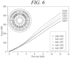
- FIG. 6 is a graph illustrating a comparison between variations in output with the change in flow rate when a slit set is changed circumferentially in position in the hydrodynamic-type hydraulic dynamometer of the exemplary embodiment.
- FIG. 7 is a graph illustrating a variation in output with the change in flow rate with respect to several opening degrees of slits in a slit set at a predetermined position in the hydrodynamic-type hydraulic dynamometer of the exemplary embodiment.
- FIG. 5 is an axial cross-sectional view illustrating a portion of an output control mechanism of the right toroidal chamber 160 of the pair of toroidal chambers
- the left side of FIG. 5 is a quarter cross-sectional view of a portion of an output control mechanism cut in a plane perpendicular to the shaft 110.
- a plurality of inner rings 170 having control slits 172 and a plurality of shutters 180 may be arranged in the circumferential direction in the pair of toroidal chambers 160.
- the plurality of shutters 180 may adjust the opening degrees of some of the plurality of control slits 172 arranged in the upper half of the toroidal chambers 160.
- the plurality of inner rings 170 may be continuously arranged in the circumferential direction, and a pocket 165 may be formed in a space below each inner ring 170 in the toroidal chamber 160.
- control slits 172 may not be formed in all of the plurality of inner rings 170, but may be formed only in some of the plurality of inner rings 170.
- the plurality of shutters 180 may be disposed only at positions in which the control slits 172 are formed.
- each of the inner rings 170 may be mounted to extend radially inwardly from the inner peripheral surface of the toroidal chamber 160 by a length of w, and each of the control slits 172 may have a radial height of h.
- each of the shutters 180 may open or close the opening height h of the control slit 172 by 0 to 100%.
- control slit 172 may be formed only on four upper half inner rings 170 among the sixteen inner rings 170.
- the variation in output with respect to the flow rate was measured for five combinations.
- FIG. 6 it can be seen that controlling the opening degrees of the four control slits 172 disposed in positions 2, 3, 6, and 7 has the best output linearity and stability.
- each control slit 172 may be selected differently depending on the maximum output. Referring to FIG. 7 , when each of the four control slits 172 disposed in positions 2, 3, 6, and 7 has a height of h1, it can be seen that the slope of the output with respect to the flow rate is smaller when the flow rate is 7 kt/hr or more. In addition, when the control slit 172 has a height of h2 which is slightly larger than h1, it can be seen that the slope of the output with respect to the flow rate becomes smaller when the flow rate is 9 kt/hr or more.
- control slit 172 has a height of h3 which is slightly larger than h2, it can be seen that the slope of the output with respect to the flow rate becomes smaller when the flow rate is 10 kt/hr or more. From these test results, it can be seen that there is an optimal height of the control slit 172 that can maintain the linearity of the output with respect to the flow rate. Accordingly, the height of the control slit 172 may be appropriately designed so that the linearity is maintained in the output graph for the flow rate according to the output range measured by the hydrodynamic-type hydraulic dynamometer.
- the large-capacity hydrodynamic-type hydraulic dynamometer with output control mechanism can control the flow rate of recirculating fluid by the shutter mechanism that controls the flow rate of fluid circulating through the toroidal chamber to solve a decrease in output and an uncontrollable phenomenon that occur in the large-capacity hydrodynamic-type hydraulic dynamometer such as load test of the large-capacity gas turbine.
Landscapes
- Physics & Mathematics (AREA)
- General Physics & Mathematics (AREA)
- Engineering & Computer Science (AREA)
- Chemical & Material Sciences (AREA)
- Combustion & Propulsion (AREA)
- Hydraulic Turbines (AREA)
- General Engineering & Computer Science (AREA)
- Mechanical Engineering (AREA)
- Measuring Volume Flow (AREA)
Claims (15)
- Dynamomètre hydraulique de type hydrodynamique (100), comprenant :un arbre (110) monté de manière rotative sur une pluralité de paliers (112) ;un stator (120) fixé autour de l'arbre et contenant une chambre toroïdale (160) ;un roue (130) accouplée de manière rotative à l'arbre et provoquant la circulation à l'intérieur de celui-ci d'un fluide introduit dans la chambre toroïdale ; caractérisé par une bague intérieure (170) montée de manière à s'étendre vers l'intérieur depuis un côté radialement extérieur de la chambre toroïdale, et dans laquelle est ménagée une fente de commande (172) ; etun obturateur (180) prévu pour régler un degré d'ouverture de la fente de commande.
- Dynamomètre hydraulique de type hydrodynamique selon la revendication 1, où la chambre toroïdale (160) comprend une paire de chambres toroïdales (160) à symétrie bilatérale, et
où la roue (130) comprend une pluralité d'aubes (132) exposées vers l'intérieur de chaque chambre de la paire de chambres toroïdales afin de faire circuler le fluide introduit dans la chambre toroïdale. - Dynamomètre hydraulique de type hydrodynamique selon la revendication 2, comprenant en outre une bague de guidage (140) disposée entre les chambres de la paire de chambres toroïdales (160) et dont les deux côtés forment une partie de la surface périphérique intérieure de chaque chambre toroïdale (160).
- Dynamomètre hydraulique de type hydrodynamique selon la revendication 3, où le stator (120) comprend en outre une chambre de vidange (190) formée radialement vers l'extérieur de la paire de chambres toroïdales (160) ; et
où la paire de chambres toroïdales (160) comprend en outre une paire de fentes de vidange (167) formées sur leurs côtés radialement extérieurs pour communiquer avec la chambre de vidange entre la paire de chambres toroïdales (160) et la bague de guidage (140). - Dynamomètre hydraulique de type hydrodynamique selon l'une des revendications précédentes, où le stator (120) présente en outre des chambres d'entrée (150) formées sur chaque côté axial de la paire de chambres toroïdales (160) ; et
où la paire de chambres toroïdales (160) comprend une paire de buses d'alimentation en fluide (162) formées sur leurs côtés radialement intérieurs pour communiquer des chambres d'entrée (150) vers les chambres toroïdales (160). - Dynamomètre hydraulique de type hydrodynamique selon l'une des revendications précédentes, où la chambre toroïdale (160) a une section transversale elliptique.
- Dynamomètre hydraulique de type hydrodynamique selon l'une des revendications précédentes, comprenant en outre un actionneur (210) monté sur une surface périphérique extérieure du stator pour déplacer l'obturateur (180) dans une direction radiale.
- Dynamomètre hydraulique de type hydrodynamique selon la revendication 7, comprenant en outre un capteur de déplacement (220) prévu sur un côté de l'actionneur (210) afin de mesurer un déplacement de l'obturateur (180).
- Dynamomètre hydraulique de type hydrodynamique selon la revendication 8, comprenant en outre une butée (230) prévue radialement à l'intérieur de l'actionneur (210) pour limiter un déplacement maximal de l'actionneur.
- Dynamomètre hydraulique de type hydrodynamique (100) selon la revendication 1,où le stator (120) contient une paire de chambres toroïdales (160) ;où la roue (130) comprend une pluralité d'aubes afin de faire circuler un fluide introduit dans la paire de chambres toroïdales (160) ;où la bague intérieure est prévu comme paire de bagues intérieures (170) montées de manière à s'étendre vers l'intérieur depuis des côtés radialement extérieurs de la paire de chambres toroïdales (160), et dans chacune desquelles est formée une fente de commande (172) ;où ledit dynamomètre hydraulique de type hydrodynamique comprend en outre une bague de guidage (140) disposée entre les chambres de la paire de chambres toroïdales (160) et dont les deux côtés forment une partie de la surface périphérique intérieure de chaque chambre toroïdale (160) ; etoù l'obturateur est prévu comme paire d'obturateurs (180), dont chacun est prévu pour réglé un degré d'ouverture de d'une fente correspondante parmi les fentes de commande (172).
- Dynamomètre hydraulique de type hydrodynamique selon la revendication 10, comprenant en outre :un actionneur (210) monté sur une surface périphérique extérieure du stator pour déplacer un des obturateurs correspondant dans une direction radiale ; etune butée (230) prévue radialement à l'intérieur de l'actionneur (210) pour limiter un déplacement maximal de l'actionneur (210).
- Dynamomètre hydraulique de type hydrodynamique selon la revendication 11, comprenant en outre un capteur de déplacement (220) prévu sur un côté de l'actionneur (210) afin de mesurer un déplacement de l'obturateur (180) correspondant.
- Dynamomètre hydraulique de type hydrodynamique selon la revendication 10, où le stator (120) comprend en outre une paire de chambres d'entrée (150) formées sur chaque côté axial de la paire de chambres toroïdales (160), et une chambre de vidange (190) formée radialement vers l'extérieur de la paire de chambres toroïdales (160).
- Dynamomètre hydraulique de type hydrodynamique selon la revendication 13, où la paire de chambres toroïdales (160) comprend une paire de buses d'alimentation en fluide (162) formées sur leurs côtés radialement intérieurs pour communiquer des chambres d'entrée (150) vers les chambres toroïdales (160) ; et
où la paire de chambres toroïdales (160) comprend en outre une paire de fentes de vidange (167) formées sur leurs côtés radialement extérieurs pour communiquer avec la chambre de vidange (190) entre la paire de chambres toroïdales (160) et la bague de guidage (140). - Dynamomètre hydraulique de type hydrodynamique selon la revendication 11, où la paire de bagues intérieures (170) dont chacune présente la fente de commande (172) et l'obturateur (180) comprennent chacune une pluralité de bagues intérieures (170) avec une pluralité de fentes de commande (172) et une pluralité d'obturateurs (180) disposés circonférentiellement dans la paire de chambres toroïdales (160), et où la pluralité d'obturateurs (180) règlent le degré d'ouverture de la pluralité de fentes de commande (172) prévues dans des moitiés supérieures des chambres toroïdales (160).
Applications Claiming Priority (1)
| Application Number | Priority Date | Filing Date | Title |
|---|---|---|---|
| KR1020210068914A KR102452601B1 (ko) | 2021-05-28 | 2021-05-28 | 출력 제어 메커니즘을 가진 대용량 유동형 수동력계 |
Publications (2)
| Publication Number | Publication Date |
|---|---|
| EP4095501A1 EP4095501A1 (fr) | 2022-11-30 |
| EP4095501B1 true EP4095501B1 (fr) | 2024-03-27 |
Family
ID=81210403
Family Applications (1)
| Application Number | Title | Priority Date | Filing Date |
|---|---|---|---|
| EP22166704.1A Active EP4095501B1 (fr) | 2021-05-28 | 2022-04-05 | Dynamomètre hydraulique de grande capacité de type hydrodynamique doté d'un mécanisme de contrôle de sortie |
Country Status (3)
| Country | Link |
|---|---|
| US (1) | US11747219B2 (fr) |
| EP (1) | EP4095501B1 (fr) |
| KR (1) | KR102452601B1 (fr) |
Families Citing this family (4)
| Publication number | Priority date | Publication date | Assignee | Title |
|---|---|---|---|---|
| KR102452601B1 (ko) * | 2021-05-28 | 2022-10-06 | 두산에너빌리티 주식회사 | 출력 제어 메커니즘을 가진 대용량 유동형 수동력계 |
| KR102608442B1 (ko) * | 2021-06-21 | 2023-12-01 | 두산에너빌리티 주식회사 | 다이나모 |
| CN116818161B (zh) * | 2022-12-30 | 2026-04-17 | 江苏联测机电科技股份有限公司 | 一种孔盘式水力测功器 |
| CN116183075A (zh) * | 2022-12-30 | 2023-05-30 | 江苏联测机电科技股份有限公司 | 一种水力测功器的定子转子结构 |
Family Cites Families (18)
| Publication number | Priority date | Publication date | Assignee | Title |
|---|---|---|---|---|
| US2428005A (en) | 1941-02-19 | 1947-09-30 | Bennett Feragen Inc | Dynamometer |
| DE834761C (de) | 1949-12-08 | 1952-03-24 | Herbert Zoellner | Wasserwirbelbremse zur Messung des Drehmomentes von Kraftmaschinen |
| JPH0639314Y2 (ja) * | 1988-11-04 | 1994-10-12 | 株式会社フチノ製作所 | 水制動力計の制御装置 |
| US6572509B2 (en) | 2000-10-23 | 2003-06-03 | Nsk, Ltd. | Toroidal-type continuously variable transmission |
| US7032464B2 (en) | 2002-05-31 | 2006-04-25 | Honeywell International, Inc. | Closed-loop waterbrake dynamometer fluid volumetric control system and method |
| DE10233091A1 (de) | 2002-07-19 | 2004-01-29 | Daimlerchrysler Ag | Wechselgetriebe mit einem stufenlosen Toroidgetriebe |
| ATE415572T1 (de) | 2004-09-03 | 2008-12-15 | Luk Lamellen & Kupplungsbau | Drehmomentübertragungseinrichtung |
| ITMI20050029A1 (it) | 2005-01-13 | 2006-07-14 | Eliodoro Pomar | Cinematismo privo di parti in moto alternativo capace di trasformare le variazioni di pressione di un fluido operante in camere toroidali a volume ciclicamente variabile in lavoro meccanico reso disponibile su un asse ruotante e motore dotato di tale |
| EP2018534B1 (fr) * | 2006-05-16 | 2017-10-25 | Rototest International AB | Procédé et dispositif pour essais dynamométriques d'un véhicule motorisé et de composants de véhicule |
| US7942249B2 (en) | 2007-09-21 | 2011-05-17 | General Electric Company | Systems and methods for controlling the stability of a water brake dynamometer |
| KR101810599B1 (ko) | 2008-10-30 | 2017-12-20 | 파워 제네레이션 테크놀로지스 디베럽먼트 펀드 엘. 피. | 환상면 경계층 가스 터빈 |
| US8695564B2 (en) | 2010-02-04 | 2014-04-15 | Dalhousie University | Toroidal engine |
| US9095856B2 (en) | 2010-02-10 | 2015-08-04 | Dresser-Rand Company | Separator fluid collector and method |
| US10900851B1 (en) * | 2020-04-16 | 2021-01-26 | Southern Dynamometer Company, LLC | Dynamometer |
| CN111896157A (zh) * | 2020-07-17 | 2020-11-06 | 中国船舶重工集团公司第七O三研究所无锡分部 | 一种大功率高速水力测功器 |
| KR102452601B1 (ko) * | 2021-05-28 | 2022-10-06 | 두산에너빌리티 주식회사 | 출력 제어 메커니즘을 가진 대용량 유동형 수동력계 |
| KR102608442B1 (ko) * | 2021-06-21 | 2023-12-01 | 두산에너빌리티 주식회사 | 다이나모 |
| US20230057234A1 (en) * | 2021-08-19 | 2023-02-23 | Pratt & Whitney Canada Corp. | Method and system for operating an aircraft having a turboprop engine |
-
2021
- 2021-05-28 KR KR1020210068914A patent/KR102452601B1/ko active Active
-
2022
- 2022-03-15 US US17/694,667 patent/US11747219B2/en active Active
- 2022-04-05 EP EP22166704.1A patent/EP4095501B1/fr active Active
Also Published As
| Publication number | Publication date |
|---|---|
| KR102452601B1 (ko) | 2022-10-06 |
| US11747219B2 (en) | 2023-09-05 |
| US20220381629A1 (en) | 2022-12-01 |
| EP4095501A1 (fr) | 2022-11-30 |
Similar Documents
| Publication | Publication Date | Title |
|---|---|---|
| EP4095501B1 (fr) | Dynamomètre hydraulique de grande capacité de type hydrodynamique doté d'un mécanisme de contrôle de sortie | |
| US6074167A (en) | Variable geometry centrifugal pump | |
| EP2589753B1 (fr) | Disque de turbine avec pales pour le refroidissement des aubes montées sur ledit disque, et méthode de refroidissement d'aube de turbine correspondante. | |
| EP0037432B1 (fr) | Turbine hydraulique à flux contrôlé | |
| EP2943726B1 (fr) | Unité de traitement d'air | |
| EP0707148A1 (fr) | Pompe | |
| US10352188B2 (en) | Centrifugal turbo machine having stretchable and variable diffuser vane | |
| EP3406915B1 (fr) | Compresseur centrifuge ayant un diffuseur variable avec paroi terminale à translation axiale | |
| KR20040004577A (ko) | 회전식 캠 링을 구비하는 가변 용적형 펌프 | |
| EP4296523A1 (fr) | Conception de compresseur/rotor soufflant caréné à géométrie variable | |
| EP4108887B1 (fr) | Dynamomètre | |
| KR102113682B1 (ko) | 터빈 블레이드 | |
| JP3981143B1 (ja) | 発電装置 | |
| KR101876161B1 (ko) | 누설 유동이 감소된 원심 펌프 | |
| US11136895B2 (en) | Spiraling grooves as a hub treatment for cantilevered stators in compressors | |
| US11713768B1 (en) | Impeller for a centrifugal pump | |
| CA2614459C (fr) | Montage d'aubes | |
| RU2715459C1 (ru) | Турбокомпрессор с надроторным устройством | |
| KR102122152B1 (ko) | 베인 및 로터의 조립체가 개선된 터빈 | |
| KR101619134B1 (ko) | 나선-디스크형 유체기계 | |
| RU2588309C2 (ru) | Гидроэлектростанция | |
| CN117108361A (zh) | 一种汽轮机叶片以及汽轮机 | |
| JP2016142209A (ja) | Vpc発電に使用するノズル構造 | |
| JP2024130465A5 (fr) | ||
| GB2324340A (en) | Rotary vane pump or motor |
Legal Events
| Date | Code | Title | Description |
|---|---|---|---|
| PUAI | Public reference made under article 153(3) epc to a published international application that has entered the european phase |
Free format text: ORIGINAL CODE: 0009012 |
|
| STAA | Information on the status of an ep patent application or granted ep patent |
Free format text: STATUS: REQUEST FOR EXAMINATION WAS MADE |
|
| 17P | Request for examination filed |
Effective date: 20220405 |
|
| AK | Designated contracting states |
Kind code of ref document: A1 Designated state(s): AL AT BE BG CH CY CZ DE DK EE ES FI FR GB GR HR HU IE IS IT LI LT LU LV MC MK MT NL NO PL PT RO RS SE SI SK SM TR |
|
| RBV | Designated contracting states (corrected) |
Designated state(s): AL AT BE BG CH CY CZ DE DK EE ES FI FR GB GR HR HU IE IS IT LI LT LU LV MC MK MT NL NO PL PT RO RS SE SI SK SM TR |
|
| GRAP | Despatch of communication of intention to grant a patent |
Free format text: ORIGINAL CODE: EPIDOSNIGR1 |
|
| STAA | Information on the status of an ep patent application or granted ep patent |
Free format text: STATUS: GRANT OF PATENT IS INTENDED |
|
| INTG | Intention to grant announced |
Effective date: 20240108 |
|
| GRAS | Grant fee paid |
Free format text: ORIGINAL CODE: EPIDOSNIGR3 |
|
| GRAA | (expected) grant |
Free format text: ORIGINAL CODE: 0009210 |
|
| STAA | Information on the status of an ep patent application or granted ep patent |
Free format text: STATUS: THE PATENT HAS BEEN GRANTED |
|
| AK | Designated contracting states |
Kind code of ref document: B1 Designated state(s): AL AT BE BG CH CY CZ DE DK EE ES FI FR GB GR HR HU IE IS IT LI LT LU LV MC MK MT NL NO PL PT RO RS SE SI SK SM TR |
|
| REG | Reference to a national code |
Ref country code: GB Ref legal event code: FG4D |
|
| REG | Reference to a national code |
Ref country code: CH Ref legal event code: EP |
|
| REG | Reference to a national code |
Ref country code: DE Ref legal event code: R096 Ref document number: 602022002509 Country of ref document: DE |
|
| REG | Reference to a national code |
Ref country code: IE Ref legal event code: FG4D |
|
| PG25 | Lapsed in a contracting state [announced via postgrant information from national office to epo] |
Ref country code: LT Free format text: LAPSE BECAUSE OF FAILURE TO SUBMIT A TRANSLATION OF THE DESCRIPTION OR TO PAY THE FEE WITHIN THE PRESCRIBED TIME-LIMIT Effective date: 20240327 |
|
| REG | Reference to a national code |
Ref country code: LT Ref legal event code: MG9D |
|
| PG25 | Lapsed in a contracting state [announced via postgrant information from national office to epo] |
Ref country code: GR Free format text: LAPSE BECAUSE OF FAILURE TO SUBMIT A TRANSLATION OF THE DESCRIPTION OR TO PAY THE FEE WITHIN THE PRESCRIBED TIME-LIMIT Effective date: 20240628 |
|
| PG25 | Lapsed in a contracting state [announced via postgrant information from national office to epo] |
Ref country code: HR Free format text: LAPSE BECAUSE OF FAILURE TO SUBMIT A TRANSLATION OF THE DESCRIPTION OR TO PAY THE FEE WITHIN THE PRESCRIBED TIME-LIMIT Effective date: 20240327 Ref country code: RS Free format text: LAPSE BECAUSE OF FAILURE TO SUBMIT A TRANSLATION OF THE DESCRIPTION OR TO PAY THE FEE WITHIN THE PRESCRIBED TIME-LIMIT Effective date: 20240627 |
|
| PG25 | Lapsed in a contracting state [announced via postgrant information from national office to epo] |
Ref country code: RS Free format text: LAPSE BECAUSE OF FAILURE TO SUBMIT A TRANSLATION OF THE DESCRIPTION OR TO PAY THE FEE WITHIN THE PRESCRIBED TIME-LIMIT Effective date: 20240627 Ref country code: NO Free format text: LAPSE BECAUSE OF FAILURE TO SUBMIT A TRANSLATION OF THE DESCRIPTION OR TO PAY THE FEE WITHIN THE PRESCRIBED TIME-LIMIT Effective date: 20240627 Ref country code: LT Free format text: LAPSE BECAUSE OF FAILURE TO SUBMIT A TRANSLATION OF THE DESCRIPTION OR TO PAY THE FEE WITHIN THE PRESCRIBED TIME-LIMIT Effective date: 20240327 Ref country code: HR Free format text: LAPSE BECAUSE OF FAILURE TO SUBMIT A TRANSLATION OF THE DESCRIPTION OR TO PAY THE FEE WITHIN THE PRESCRIBED TIME-LIMIT Effective date: 20240327 Ref country code: GR Free format text: LAPSE BECAUSE OF FAILURE TO SUBMIT A TRANSLATION OF THE DESCRIPTION OR TO PAY THE FEE WITHIN THE PRESCRIBED TIME-LIMIT Effective date: 20240628 Ref country code: FI Free format text: LAPSE BECAUSE OF FAILURE TO SUBMIT A TRANSLATION OF THE DESCRIPTION OR TO PAY THE FEE WITHIN THE PRESCRIBED TIME-LIMIT Effective date: 20240327 Ref country code: BG Free format text: LAPSE BECAUSE OF FAILURE TO SUBMIT A TRANSLATION OF THE DESCRIPTION OR TO PAY THE FEE WITHIN THE PRESCRIBED TIME-LIMIT Effective date: 20240327 |
|
| REG | Reference to a national code |
Ref country code: NL Ref legal event code: MP Effective date: 20240327 |
|
| PG25 | Lapsed in a contracting state [announced via postgrant information from national office to epo] |
Ref country code: SE Free format text: LAPSE BECAUSE OF FAILURE TO SUBMIT A TRANSLATION OF THE DESCRIPTION OR TO PAY THE FEE WITHIN THE PRESCRIBED TIME-LIMIT Effective date: 20240327 Ref country code: LV Free format text: LAPSE BECAUSE OF FAILURE TO SUBMIT A TRANSLATION OF THE DESCRIPTION OR TO PAY THE FEE WITHIN THE PRESCRIBED TIME-LIMIT Effective date: 20240327 |
|
| PG25 | Lapsed in a contracting state [announced via postgrant information from national office to epo] |
Ref country code: NL Free format text: LAPSE BECAUSE OF FAILURE TO SUBMIT A TRANSLATION OF THE DESCRIPTION OR TO PAY THE FEE WITHIN THE PRESCRIBED TIME-LIMIT Effective date: 20240327 |
|
| REG | Reference to a national code |
Ref country code: AT Ref legal event code: MK05 Ref document number: 1670335 Country of ref document: AT Kind code of ref document: T Effective date: 20240327 |
|
| PG25 | Lapsed in a contracting state [announced via postgrant information from national office to epo] |
Ref country code: NL Free format text: LAPSE BECAUSE OF FAILURE TO SUBMIT A TRANSLATION OF THE DESCRIPTION OR TO PAY THE FEE WITHIN THE PRESCRIBED TIME-LIMIT Effective date: 20240327 |
|
| PG25 | Lapsed in a contracting state [announced via postgrant information from national office to epo] |
Ref country code: IS Free format text: LAPSE BECAUSE OF FAILURE TO SUBMIT A TRANSLATION OF THE DESCRIPTION OR TO PAY THE FEE WITHIN THE PRESCRIBED TIME-LIMIT Effective date: 20240727 |
|
| PG25 | Lapsed in a contracting state [announced via postgrant information from national office to epo] |
Ref country code: SM Free format text: LAPSE BECAUSE OF FAILURE TO SUBMIT A TRANSLATION OF THE DESCRIPTION OR TO PAY THE FEE WITHIN THE PRESCRIBED TIME-LIMIT Effective date: 20240327 Ref country code: PT Free format text: LAPSE BECAUSE OF FAILURE TO SUBMIT A TRANSLATION OF THE DESCRIPTION OR TO PAY THE FEE WITHIN THE PRESCRIBED TIME-LIMIT Effective date: 20240729 |
|
| PG25 | Lapsed in a contracting state [announced via postgrant information from national office to epo] |
Ref country code: ES Free format text: LAPSE BECAUSE OF FAILURE TO SUBMIT A TRANSLATION OF THE DESCRIPTION OR TO PAY THE FEE WITHIN THE PRESCRIBED TIME-LIMIT Effective date: 20240327 |
|
| PG25 | Lapsed in a contracting state [announced via postgrant information from national office to epo] |
Ref country code: EE Free format text: LAPSE BECAUSE OF FAILURE TO SUBMIT A TRANSLATION OF THE DESCRIPTION OR TO PAY THE FEE WITHIN THE PRESCRIBED TIME-LIMIT Effective date: 20240327 Ref country code: CZ Free format text: LAPSE BECAUSE OF FAILURE TO SUBMIT A TRANSLATION OF THE DESCRIPTION OR TO PAY THE FEE WITHIN THE PRESCRIBED TIME-LIMIT Effective date: 20240327 |
|
| PG25 | Lapsed in a contracting state [announced via postgrant information from national office to epo] |
Ref country code: AT Free format text: LAPSE BECAUSE OF FAILURE TO SUBMIT A TRANSLATION OF THE DESCRIPTION OR TO PAY THE FEE WITHIN THE PRESCRIBED TIME-LIMIT Effective date: 20240327 |
|
| PG25 | Lapsed in a contracting state [announced via postgrant information from national office to epo] |
Ref country code: PL Free format text: LAPSE BECAUSE OF FAILURE TO SUBMIT A TRANSLATION OF THE DESCRIPTION OR TO PAY THE FEE WITHIN THE PRESCRIBED TIME-LIMIT Effective date: 20240327 |
|
| PG25 | Lapsed in a contracting state [announced via postgrant information from national office to epo] |
Ref country code: SK Free format text: LAPSE BECAUSE OF FAILURE TO SUBMIT A TRANSLATION OF THE DESCRIPTION OR TO PAY THE FEE WITHIN THE PRESCRIBED TIME-LIMIT Effective date: 20240327 |
|
| PG25 | Lapsed in a contracting state [announced via postgrant information from national office to epo] |
Ref country code: SM Free format text: LAPSE BECAUSE OF FAILURE TO SUBMIT A TRANSLATION OF THE DESCRIPTION OR TO PAY THE FEE WITHIN THE PRESCRIBED TIME-LIMIT Effective date: 20240327 Ref country code: SK Free format text: LAPSE BECAUSE OF FAILURE TO SUBMIT A TRANSLATION OF THE DESCRIPTION OR TO PAY THE FEE WITHIN THE PRESCRIBED TIME-LIMIT Effective date: 20240327 Ref country code: RO Free format text: LAPSE BECAUSE OF FAILURE TO SUBMIT A TRANSLATION OF THE DESCRIPTION OR TO PAY THE FEE WITHIN THE PRESCRIBED TIME-LIMIT Effective date: 20240327 Ref country code: PT Free format text: LAPSE BECAUSE OF FAILURE TO SUBMIT A TRANSLATION OF THE DESCRIPTION OR TO PAY THE FEE WITHIN THE PRESCRIBED TIME-LIMIT Effective date: 20240729 Ref country code: PL Free format text: LAPSE BECAUSE OF FAILURE TO SUBMIT A TRANSLATION OF THE DESCRIPTION OR TO PAY THE FEE WITHIN THE PRESCRIBED TIME-LIMIT Effective date: 20240327 Ref country code: IS Free format text: LAPSE BECAUSE OF FAILURE TO SUBMIT A TRANSLATION OF THE DESCRIPTION OR TO PAY THE FEE WITHIN THE PRESCRIBED TIME-LIMIT Effective date: 20240727 Ref country code: ES Free format text: LAPSE BECAUSE OF FAILURE TO SUBMIT A TRANSLATION OF THE DESCRIPTION OR TO PAY THE FEE WITHIN THE PRESCRIBED TIME-LIMIT Effective date: 20240327 Ref country code: EE Free format text: LAPSE BECAUSE OF FAILURE TO SUBMIT A TRANSLATION OF THE DESCRIPTION OR TO PAY THE FEE WITHIN THE PRESCRIBED TIME-LIMIT Effective date: 20240327 Ref country code: CZ Free format text: LAPSE BECAUSE OF FAILURE TO SUBMIT A TRANSLATION OF THE DESCRIPTION OR TO PAY THE FEE WITHIN THE PRESCRIBED TIME-LIMIT Effective date: 20240327 Ref country code: AT Free format text: LAPSE BECAUSE OF FAILURE TO SUBMIT A TRANSLATION OF THE DESCRIPTION OR TO PAY THE FEE WITHIN THE PRESCRIBED TIME-LIMIT Effective date: 20240327 |
|
| PG25 | Lapsed in a contracting state [announced via postgrant information from national office to epo] |
Ref country code: IT Free format text: LAPSE BECAUSE OF FAILURE TO SUBMIT A TRANSLATION OF THE DESCRIPTION OR TO PAY THE FEE WITHIN THE PRESCRIBED TIME-LIMIT Effective date: 20240327 |
|
| PG25 | Lapsed in a contracting state [announced via postgrant information from national office to epo] |
Ref country code: LU Free format text: LAPSE BECAUSE OF NON-PAYMENT OF DUE FEES Effective date: 20240405 |
|
| REG | Reference to a national code |
Ref country code: BE Ref legal event code: MM Effective date: 20240430 |
|
| PG25 | Lapsed in a contracting state [announced via postgrant information from national office to epo] |
Ref country code: LU Free format text: LAPSE BECAUSE OF NON-PAYMENT OF DUE FEES Effective date: 20240405 Ref country code: IT Free format text: LAPSE BECAUSE OF FAILURE TO SUBMIT A TRANSLATION OF THE DESCRIPTION OR TO PAY THE FEE WITHIN THE PRESCRIBED TIME-LIMIT Effective date: 20240327 |
|
| REG | Reference to a national code |
Ref country code: DE Ref legal event code: R097 Ref document number: 602022002509 Country of ref document: DE |
|
| PG25 | Lapsed in a contracting state [announced via postgrant information from national office to epo] |
Ref country code: MC Free format text: LAPSE BECAUSE OF FAILURE TO SUBMIT A TRANSLATION OF THE DESCRIPTION OR TO PAY THE FEE WITHIN THE PRESCRIBED TIME-LIMIT Effective date: 20240327 |
|
| PG25 | Lapsed in a contracting state [announced via postgrant information from national office to epo] |
Ref country code: DK Free format text: LAPSE BECAUSE OF FAILURE TO SUBMIT A TRANSLATION OF THE DESCRIPTION OR TO PAY THE FEE WITHIN THE PRESCRIBED TIME-LIMIT Effective date: 20240327 |
|
| PG25 | Lapsed in a contracting state [announced via postgrant information from national office to epo] |
Ref country code: BE Free format text: LAPSE BECAUSE OF NON-PAYMENT OF DUE FEES Effective date: 20240430 |
|
| PG25 | Lapsed in a contracting state [announced via postgrant information from national office to epo] |
Ref country code: MC Free format text: LAPSE BECAUSE OF FAILURE TO SUBMIT A TRANSLATION OF THE DESCRIPTION OR TO PAY THE FEE WITHIN THE PRESCRIBED TIME-LIMIT Effective date: 20240327 Ref country code: DK Free format text: LAPSE BECAUSE OF FAILURE TO SUBMIT A TRANSLATION OF THE DESCRIPTION OR TO PAY THE FEE WITHIN THE PRESCRIBED TIME-LIMIT Effective date: 20240327 Ref country code: BE Free format text: LAPSE BECAUSE OF NON-PAYMENT OF DUE FEES Effective date: 20240430 |
|
| PLBE | No opposition filed within time limit |
Free format text: ORIGINAL CODE: 0009261 |
|
| STAA | Information on the status of an ep patent application or granted ep patent |
Free format text: STATUS: NO OPPOSITION FILED WITHIN TIME LIMIT |
|
| 26N | No opposition filed |
Effective date: 20250103 |
|
| PG25 | Lapsed in a contracting state [announced via postgrant information from national office to epo] |
Ref country code: IE Free format text: LAPSE BECAUSE OF NON-PAYMENT OF DUE FEES Effective date: 20240405 |
|
| PG25 | Lapsed in a contracting state [announced via postgrant information from national office to epo] |
Ref country code: SI Free format text: LAPSE BECAUSE OF FAILURE TO SUBMIT A TRANSLATION OF THE DESCRIPTION OR TO PAY THE FEE WITHIN THE PRESCRIBED TIME-LIMIT Effective date: 20240327 |
|
| PGFP | Annual fee paid to national office [announced via postgrant information from national office to epo] |
Ref country code: DE Payment date: 20250225 Year of fee payment: 4 |
|
| PG25 | Lapsed in a contracting state [announced via postgrant information from national office to epo] |
Ref country code: CY Free format text: LAPSE BECAUSE OF FAILURE TO SUBMIT A TRANSLATION OF THE DESCRIPTION OR TO PAY THE FEE WITHIN THE PRESCRIBED TIME-LIMIT; INVALID AB INITIO Effective date: 20220405 |
|
| REG | Reference to a national code |
Ref country code: CH Ref legal event code: H13 Free format text: ST27 STATUS EVENT CODE: U-0-0-H10-H13 (AS PROVIDED BY THE NATIONAL OFFICE) Effective date: 20251125 |
|
| PG25 | Lapsed in a contracting state [announced via postgrant information from national office to epo] |
Ref country code: TR Free format text: LAPSE BECAUSE OF FAILURE TO SUBMIT A TRANSLATION OF THE DESCRIPTION OR TO PAY THE FEE WITHIN THE PRESCRIBED TIME-LIMIT Effective date: 20240327 |
|
| PG25 | Lapsed in a contracting state [announced via postgrant information from national office to epo] |
Ref country code: CH Free format text: LAPSE BECAUSE OF NON-PAYMENT OF DUE FEES Effective date: 20250430 |
|
| PGFP | Annual fee paid to national office [announced via postgrant information from national office to epo] |
Ref country code: FR Payment date: 20260223 Year of fee payment: 5 |