EP4095525B1 - Verfahren und ionenführungsanordnung zur modulation eines ionenstroms - Google Patents
Verfahren und ionenführungsanordnung zur modulation eines ionenstroms Download PDFInfo
- Publication number
- EP4095525B1 EP4095525B1 EP21176300.8A EP21176300A EP4095525B1 EP 4095525 B1 EP4095525 B1 EP 4095525B1 EP 21176300 A EP21176300 A EP 21176300A EP 4095525 B1 EP4095525 B1 EP 4095525B1
- Authority
- EP
- European Patent Office
- Prior art keywords
- ion
- ions
- ion guide
- guide path
- conveying
- Prior art date
- Legal status (The legal status is an assumption and is not a legal conclusion. Google has not performed a legal analysis and makes no representation as to the accuracy of the status listed.)
- Active
Links
Images
Classifications
-
- G—PHYSICS
- G01—MEASURING; TESTING
- G01N—INVESTIGATING OR ANALYSING MATERIALS BY DETERMINING THEIR CHEMICAL OR PHYSICAL PROPERTIES
- G01N27/00—Investigating or analysing materials by the use of electric, electrochemical, or magnetic means
- G01N27/62—Investigating or analysing materials by the use of electric, electrochemical, or magnetic means by investigating the ionisation of gases, e.g. aerosols; by investigating electric discharges, e.g. emission of cathode
- G01N27/622—Ion mobility spectrometry
-
- H—ELECTRICITY
- H01—ELECTRIC ELEMENTS
- H01J—ELECTRIC DISCHARGE TUBES OR DISCHARGE LAMPS
- H01J49/00—Particle spectrometers or separator tubes
- H01J49/02—Details
- H01J49/06—Electron- or ion-optical arrangements
- H01J49/062—Ion guides
Definitions
- the invention relates to a method for, in an ion guide, modulating a stream of ions according to a modulation function.
- the invention further relates to an ion guide assembly for modulating a stream of ions according to a modulation function with the method according to the invention.
- EP 1 367 633 A2 of Micromass Limited discloses an ion guide assembly for conveying ions along an ion guide path in a conveying direction.
- the ion guide of this ion guide assembly comprises a plurality of electrodes.
- a sequence of DC voltages is applied to each one of the electrodes.
- a DC potential waveform is generated along the ion guide path.
- This DC potential waveform is seen by the ions as a DC potential well which moves in conveying direction along the ion guide path.
- the ions ride on or with the travelling DC potential wells that are being translated along the ion guide path. Since there is a neutral gas in the ion guide, ions may however be pushed out of a travelling DC potential well by the resistance of the neutral gas. Such ions are then trapped by the succeeding travelling DC potential well. There, the ions may again be pushed out of the travelling DC potential well and again be trapped by the succeeding travelling DC potential well.
- the larger the collision cross section of an ion the higher is the probability for the ion to be pushed out of a travelling DC potential well. Consequently, larger ions take longer to traverse a given distance. Therefore, the mobility of the ions can be calculated based on the time they require to traverse a given distance.
- the ion guide comprises at least three conveying electrodes arranged in a succession of each other along the ion guide path.
- a radio frequency AC voltage control circuitry is connected to the at least three conveying electrodes for supplying each of the at least three conveying electrodes with a radio frequency AC voltage, wherein for each one of the at least three conveying electrodes which is succeeding in the succession of the at least three conveying electrodes a preceding neighbouring conveying electrode of the at least three conveying electrodes, the radio frequency AC voltage has essentially a same frequency, essentially a same maximum amplitude and a phase increased by an amount in a range from 10° to 170° as compared to for the respective preceding neighbouring conveying electrode for generating a radio frequency AC potential wave along the ion guide path moving in the conveying direction for conveying the ions along the ion guide path in the conveying direction.
- the device includes a pair of substantially parallel surfaces.
- An array of inner electrodes is contained within each parallel surface and extends substantially along the length of each parallel surface.
- the device further includes a first outer array of electrodes and a second outer array of electrodes. Each outer array of electrodes is positioned on either side of the inner electrodes, and is contained within and extends substantially along the length of each parallel surface.
- a DC voltage is applied to the first and second outer array of electrodes and an RF voltage with a superimposed electric field is applied to the inner electrodes by applying the DC voltages to each electrode.
- the mobility of the ions is determined by determining the time the ions require to pass through an ion mobility separation cell. In order to determine this time, a stream of ions is modulated according to a modulation function and then passed through the ion mobility separation cell, whereafter the ions are detected with an ion detector.
- a modulation function is modulated according to a modulation function and then passed through the ion mobility separation cell, whereafter the ions are detected with an ion detector.
- the modulation function consists of regular or irregular pulses with pauses in between which are enough long such that the slowest ions of a particular pulse arrive at the ion detector before the fastest ions of the subsequent pulse arrive at the ion detector in order to be able to assign the detected ions to a particular pulse.
- the time difference between the pulse and the arrival of the ions at the ion detector is directly related to the mobility of the ions. Therefore, by knowing the gas pressure in the ion mobility separation cell, the mobility of the ions can be determined from the time difference between the pulse and the arrival of the ions at the ion detector.
- the modulation function provides pulses of identical or varying width in time and varying gaps between the pulses which are relatively short such that the slowest ions of a particular pulse may arrive at the ion detector after the fastest ions of the subsequent pulse have arrived at the ion detector.
- the measurement can be multiplexed in that the modulation function is chosen to have an autocorrelation which is a two-valued function. This means that the autocorrelation function has a peak at one value like for example at zero and a constant value at all other values.
- the mobility of the ions is obtained by calculating the correlation of the modulation function and the signal obtained from the ion detector.
- the mobility of the ions can be determined from the time distribution by scaling as known in the art, for example by knowing the gas pressure in the ion mobility separation cell or by instrument calibration.
- the accuracy of the determined mobility of ions depends strongly on the width and shape of the pulses of the ions which are inserted into the ion mobility separation cell.
- the accuracy of the determined mobility of ions depends strongly on how precisely the stream of ions is modulated according to the modulation function.
- distortions in the shape of the pulses of the ions that are inserted into the ion mobility separation cell lead to artificial features in the obtained ion mobility spectra which can mistakenly be understood as ions having a certain mobility corresponding to the position of these artificial features in the obtained ion mobility spectra.
- One way to improve the shape of the ion pulses is to incorporate the ion gate into the ion guide.
- the ion guide includes an ion gate for modulating a stream of ions according to a modulation function for performing ion mobility spectrometry is described in the article " Masked Multiplexed Separations to Enhance Duty Cycle for Structures for Lossless Ion Manipulations" of Brian H. Clowers et al., Analytical Chemistry, 2021, 93, 14, 5727 - 5734 . However, this solution still leaves a lot of space for improving the preciseness with which the stream of ions is modulated according to the modulation function.
- the known methods for, in an ion guide, modulating a stream of ions according to a modulation function and the known ion guide assemblies for modulating a stream of ions according to a modulation function do not enable modulating the stream of ions precise enough according to the respective modulation function.
- the stream of ions includes at least N different ion species, wherein N is at least 1.
- the ion guide forms an ion guide path, wherein the ions of the stream of ions are conveyed along the ion guide path in a conveying direction to form the stream of ions.
- the ion guide includes an ion gate arranged at an ion gate position on the ion guide path, wherein the ion gate is adapted to provide an open state for allowing the ions passing the ion gate position when being conveyed along the ion guide path and a closed state for preventing the ions from passing the ion gate position.
- the ion guide further includes a first arrangement of conveying electrodes arranged along the ion guide path, the first arrangement of conveying electrodes extending over a first section of the ion guide path, wherein the first section of the ion guide path reaches from at least the ion gate position downstream to at least a transition position on the ion guide path, wherein the first arrangement of conveying electrodes is adapted for generating first travelling waves having a first travelling wave amplitude and travelling along the first section of the ion guide path at a first travelling wave velocity for conveying the ions along the first section of the ion guide path.
- the ion guide furthermore includes a second arrangement of conveying electrodes arranged along the ion guide path, the second arrangement of conveying electrodes extending over a second section of the ion guide path, wherein the second section of the ion guide path reaches from the transition position downstream, wherein the second arrangement of conveying electrodes is adapted for generating second travelling waves having a second travelling wave amplitude and travelling along the second section of the ion guide path at a second travelling wave velocity for conveying the ions along the second section of the ion guide path.
- the stream of ions is modulated with the ion gate according to the modulation function and AC voltages are applied to the first arrangement of conveying electrodes for generating the first travelling waves and to the second arrangement of conveying electrodes for generating the second travelling waves for conveying the ions downstream of the ion gate along the first section and the second section of the ion guide path in the conveying direction away from the ion gate.
- a ratio A is the average velocity of the ions of the respective ion species in the first section of the ion guide path divided by the first travelling wave velocity
- a ratio B is the average velocity of the ions of the respective ion species in the second section of the ion guide path divided by the second travelling wave velocity, wherein the first travelling wave amplitude, the first travelling wave velocity, the second travelling wave amplitude and the second travelling wave velocity are chosen such that for each ion species of the at least N different ion species, the ratio A is larger than the ratio B.
- the ion guide assembly for modulating a stream of ions according to a modulation function with the method according to the invention, wherein the stream of ions includes at least N different ion species, wherein N is at least 1, includes an ion guide which forms an ion guide path, wherein the ions of the stream of ions are conveyable along the ion guide path in a conveying direction to form the stream of ions.
- the ion guide includes an ion gate arranged at an ion gate position on the ion guide path, wherein the ion gate is adapted to provide an open state for allowing the ions passing the ion gate position when being conveyed along the ion guide path and a closed state for preventing the ions from passing the ion gate position.
- the ion guide further includes a first arrangement of conveying electrodes arranged along the ion guide path, the first arrangement of conveying electrodes extending over a first section of the ion guide path, wherein the first section of the ion guide path reaches from at least the ion gate position downstream to at least a transition position on the ion guide path, wherein the first arrangement of conveying electrodes is adapted for generating first travelling waves having a first travelling wave amplitude and travelling along the first section of the ion guide path at a first travelling wave velocity for conveying the ions along the first section of the ion guide path.
- the ion guide furthermore includes a second arrangement of conveying electrodes arranged along the ion guide path, the second arrangement of conveying electrodes extending over a second section of the ion guide path, wherein the second section of the ion guide path reaches from the transition position downstream, wherein the second arrangement of conveying electrodes is adapted for generating second travelling waves having a second travelling wave amplitude and travelling along the second section of the ion guide path at a second travelling wave velocity for conveying the ions along the second section of the ion guide path.
- the ion guide assembly includes at least one AC voltage control circuitry connectable to the first arrangement of conveying electrodes for supplying the conveying electrodes of the first arrangement of conveying electrodes with AC voltages for generating the first travelling waves for conveying the ions downstream of the ion gate along the first section of the ion guide path in the conveying direction away from the ion gate and connectable to the second arrangement of conveying electrodes for supplying the conveying electrodes of the second arrangement of conveying electrodes with AC voltages for generating the second travelling waves for conveying the ions along the second section of the ion guide path in the conveying direction away from the ion gate.
- a ratio A is the average velocity of the ions of the respective ion species in the first section of the ion guide path divided by the first travelling wave velocity
- a ratio B is the average velocity of the ions of the respective ion species in the second section of the ion guide path divided by the second travelling wave velocity
- the ion guide assembly includes a control unit adapted to control the ion guide assembly such that the first travelling wave amplitude, the first travelling wave velocity, the second travelling wave amplitude and the second travelling wave velocity are chosen such that for each ion species of the at least N different ion species, the ratio A is larger than the ratio B.
- the ion guide assembly is advantageously controlled with the control unit of the ion guide assembly such that the first travelling wave amplitude, the first travelling wave velocity, the second travelling wave amplitude and the second travelling wave velocity are chosen such that for each ion species of the at least N different ion species, the ratio A is larger than the ratio B.
- the stream of ions includes at least N different ion species, wherein N is at least 1.
- the stream of ions includes ions of the at least N different ions species, but may include further ions of other ion species, too.
- the precise number of ion species of which there are ions in the stream of ions is not needed to be known.
- all ion species obtained from a sample with a mass-to-charge ratio larger than a certain threshold can be considered as belonging to the at least N different ion species.
- all ion species obtained from a sample with a mobility larger than a certain threshold can be considered as belonging to the at least N different ion species.
- the stream of ions is advantageously formed from a sample including analytes which are atoms and/or compounds of interest, wherein these analytes belong to the N different ion species when being ionised to ions.
- the ions of the stream of ions are conveyed along the ion guide path in a conveying direction to form the stream of ions.
- the ion guide path is preferably a spatial region, wherein the ions move within the spatial region of the ion guide path when being conveyed along the ion guide path in the conveying direction. Since the conveying direction follows the course of the ion guide path and since the ion guide path does not necessarily follow a straight line but may comprise bends and curves, the conveying direction may change in space depending on the position where one looks at the ion guide path. Thus, the conveying direction indicates at each position of the ion guide path the direction along the ion guide path of the stream of ions.
- the wording downstream of a particular position on the ion guide path refers to starting from the respective particular position in the conveying direction
- the wording upstream of a particular position on the ion guide path refers to starting from the respective particular position in the opposite of the conveying direction
- the ion guide has a first end, which is also referred to as entrance end of the ion guide, and a second end, which is also referred to as exit end of the ion guide, being spatially separated from the first end, for conveying the ions of the stream of ions along the ion guide path from a first spatial region located in an area of the first end of the ion guide to a second spatial region located in an area of the second end of the ion guide.
- the ion guide path is preferably a spatial region connecting the first spatial region to the second spatial region, wherein the ions move within the spatial region of the ion guide path when being conveyed along the ion guide path in the conveying direction from the first spatial region to the second spatial region.
- the conveying direction indicates at each position of the ion guide path the direction along the ion guide path from the first spatial region to the second spatial region.
- the ions of the ion stream do not necessarily always move only in the conveying direction along the ion guide path. There may be moments where an ion moves perpendicular to the conveying direction or even countermoves the conveying direction. There is however a net movement of the ions along the ion guide path in the conveying direction. As an example for a movement of the ions not exclusively in the conveying direction, the ions can move in small circles while being conveyed along the ion guide path in the conveying direction.
- the term average velocity of the ions in the first section of the ion guide path relates to the net movement of the ions along the first section of the ion guide path in the conveying direction and thus means the net movements average velocity of the ions in the first section of the ion guide path.
- the term average velocity of the ions in the second section of the ion guide path relates to the net movement of the ions along the second section of the ion guide path in the conveying direction and thus means the net movements average velocity of the ions in the second section of the ion guide path.
- the average velocity of an ion of a particular ion species in the first section and in the second section of the ion guide path can be determined by measuring the time the respective ion requires to pass a certain distance in the respective one of the first and second section of the ion guide path.
- Such an experimental determination of the average velocity may as well be obtained by constructing an experimental ion guide having the same properties as the first or second section of the ion guide path, respectively, and measuring the time the respective ion requires to pass a certain distance in this experimental ion guide.
- Even calculated simulations of the ions movement in the respective one of the first and second section of the ion guide path can be used to determine the average velocity of the respective ion with a reasonable precise accuracy provided the modelling used for the calculated simulation is sufficient accurate.
- the ion guide includes an ion gate arranged at an ion gate position on the ion guide path. How this ion gate is precisely formed, is irrelevant. Important is that the ion gate is adapted to provide an open state for allowing the ions passing the ion gate position when being conveyed along the ion guide path and a closed state for preventing the ions from passing the ion gate position when being conveyed along the ion guide path in order to enable modulating the stream of ions with the ion gate according to the modulation function.
- the ion gate is formed of one or more ion gate electrodes on which a blocking voltage can be applied for switching and maintaining the ion gate in the closed state, wherein the ion gate is switched to the open state when the applied blocking voltage is reduced or turned off.
- a blocking voltage can be applied for switching and maintaining the ion gate in the closed state, wherein the ion gate is switched to the open state when the applied blocking voltage is reduced or turned off.
- Such an ion gate can be formed by one or more separate ion gate electrodes in the ion guide or can be formed by a set of one or more conveying electrodes of the ion guide. In this latter case, the one or more ion gate electrodes are at the same time conveying electrodes like the ion gate used in the study published in the article " Masked Multiplexed Separations to Enhance Duty Cycle for Structures for Lossless Ion Manipulations" of Brian H.
- the ion guide assembly advantageously includes a gate voltage control circuitry for applying the blocking voltage to the one or more ion gate electrodes.
- this gate voltage control circuitry is connected to the one or more ion gate electrodes for applying the blocking voltage to the one or more ion gate electrodes.
- the stream of ions is advantageously modulated with the ion gate according to the modulation function by switching the ion gate between the closed state and the open state according to the modulation function.
- the first section of the ion guide path reaches from at least the ion gate position downstream to at least a transition position on the ion guide path.
- the first section of the ion guide path advantageously ends in a downstream end at the transition position.
- the downstream end of the first section of the ion guide path is downstream of the transition position. In this case, the first section of the ion guide path and the second section of the ion guide path overlap.
- the first arrangement of conveying electrodes is adapted for generating first travelling waves having a first travelling wave amplitude and travelling along the first section of the ion guide path at a first travelling wave velocity for conveying the ions along the first section of the ion guide path.
- the first arrangement of conveying electrodes is adapted for generating the first travelling waves travelling along the entire first section of the ion guide path at the first travelling wave velocity for conveying the ions along the first section of the ion guide path.
- the ion guide includes a second arrangement of conveying electrodes arranged along the ion guide path, the second arrangement of conveying electrodes extending over a second section of the ion guide path, wherein the second section of the ion guide path reaches from the transition position downstream.
- the second section of the ion guide path has a downstream end which is located downstream of the transition position.
- the second arrangement of conveying electrodes is adapted for generating second travelling waves having a first travelling wave amplitude and travelling along the second section of the ion guide path at a second travelling wave velocity for conveying the ions along the second section of the ion guide path.
- the second arrangement of conveying electrodes is adapted for generating the second travelling waves travelling along the entire second section of the ion guide path at the travelling wave velocity for conveying the ions along the second section of the ion guide path.
- the second section of the ion guide path advantageously joins the first section of the ion guide path on the downstream end of the first section of the ion guide path.
- the first section and the second section of the ion guide path overlap from the transition position downstream until the downstream end of the first section of the ion guide path.
- the first travelling waves and the second travelling waves are in phase at the transition position.
- the first travelling waves and the second travelling waves are sometimes or always during executing the method according to the invention at the transition position out of phase.
- the AC voltages are applied to the first arrangement of conveying electrodes for generating the first travelling waves and to the second arrangement of conveying electrodes for generating the second travelling waves for conveying the ions downstream of the ion gate along the first section and the second section of the ion guide path in the conveying direction away from the ion gate.
- the AC voltages follow a periodic curve.
- This periodic curve is not required to pass through zero. It can be superposed with a constant DC-voltage and thus be shifted relative to ground or not.
- the AC voltages follow a sine curve.
- the AC voltages follow a periodic curve which is different from a sine curve.
- the periodic curve may be a continuously differentiable curve or may be a curve providing kinks and thus provide positions where it is not differentiable.
- the AC voltages may thus for example be periodical, rectangular shaped DC voltage pulses.
- the same AC voltages can be applied to the first arrangement of conveying electrodes for generating the first travelling waves and to the second arrangement of conveying electrodes for generating the second travelling waves for conveying the ions downstream of the ion gate along the first section and the second section of the ion guide path in the conveying direction away from the ion gate.
- the AC voltages applied to the first arrangement of conveying electrodes for generating the first travelling waves differ from the AC voltages applied to the second arrangement of conveying electrodes for generating the second travelling waves or conveying the ions downstream of the ion gate along the first section and the second section of the ion guide path in the conveying direction away from the ion gate.
- an electric field is generatable having a maximum strength in a range between 1 V/mm and 5'000 V/mm.
- AC voltages applied to the second arrangement of conveying electrodes are radio frequency AC voltages.
- the AC voltages applied to the first arrangement of conveying electrodes are preferably radio frequency AC voltages, too.
- the AC voltages applied to the first arrangement of conveying electrodes are not radio frequency AC voltages.
- the AC voltages applied to the first arrangement of conveying electrodes advantageously have a frequency in the range from 1 kHz to 100 kHz. In variants, however, the frequencies of the AC voltages are smaller or higher than this range.
- the AC voltages applied to the second arrangement of conveying electrodes are not radio frequency AC voltages.
- the AC voltages applied to the first arrangement of conveying electrodes are advantageously not radio frequency AC voltages either.
- the AC voltages applied to the first arrangement of conveying electrodes and the AC voltages applied to the second arrangement of conveying electrodes advantageously have a frequency in the range from 1 kHz to 100 kHz. In variants, however, the frequencies of the AC voltages are smaller or higher than this range.
- radio frequency AC voltages preferably have a frequency of 100 kHz or more, preferably 250 kHz or more, particular preferably 500 kHz or more.
- the radio frequency AC voltages have a frequency in a range from 100 kHz to 50 MHz, from 250 kHz to 50 MHz, or from 500 kHz to 50 MHz.
- the ion guide assembly includes at least one AC voltage control circuitry connectable to the first arrangement of conveying electrodes for supplying the conveying electrodes of the first arrangement of conveying electrodes with AC voltages for generating the first travelling waves for conveying the ions downstream of the ion gate along the first section of the ion guide path in the conveying direction away from the ion gate and connectable to the second arrangement of conveying electrodes for supplying the conveying electrodes of the second arrangement of conveying electrodes with AC voltages for generating the second travelling waves for conveying the ions along the second section of the ion guide path in the conveying direction away from the ion gate.
- the at least one AC voltage control circuitry is advantageously connected to the first arrangement of conveying electrodes for supplying the conveying electrodes of the first arrangement of conveying electrodes with AC voltages for generating the first travelling waves for conveying the ions downstream of the ion gate along the first section of the conveying path in the conveying direction away from the ion gate and connected to the second arrangement of conveying electrodes for supplying the conveying electrodes of the second arrangement of conveying electrodes with AC voltages for generating the second travelling waves for conveying the ions along the second section of the ion guide path in the conveying direction away from the ion gate.
- the above mentioned AC voltages are applied to the conveying electrodes of the first arrangement of conveying electrodes and to the conveying electrodes of the second arrangement of conveying electrodes by the at least one AC voltage control circuitry of the ion guide assembly when executing the method.
- the at least one AC voltage control circuitry can be one for both the first and the second arrangement of conveying electrodes or can be one for the first arrangement of conveying electrodes and another one for the second arrangement of conveying electrodes.
- Each one of the at least one AC voltage control circuitry may for example be a board, a permanent wiring or be printed on a circuit board.
- the AC voltage control circuitry comprises one or more power supplies which can each be an AC power supply or a DC power supply.
- the AC voltage control circuitry is connectable to one or more separate power supplies which can again each be an AC power supply or a DC power supply.
- the at least one AC voltage control circuitry enables supplying the conveying electrodes of the first arrangement of conveying electrodes and the conveying electrodes of the second arrangement of conveying electrodes with the respective desired AC voltage which can, as explained above, be a radio frequency AC voltage.
- the conveying electrodes of the first arrangement of conveying electrodes are arranged more compact along the ion guide path than the conveying electrodes of the second arrangement of conveying electrodes are arranged along the ion guide path.
- the conveying electrodes of the first arrangement of conveying electrodes are arranged along the ion guide path to extend less than 80%, in particular less than 60%, along the ion guide path as compared to how the conveying electrodes of the second arrangement of conveying electrodes are arranged to extend along the ion guide path.
- the spacing between the conveying electrodes of the first arrangement of conveying electrodes can be reduced as compared to the spacing of conveying electrodes of the second arrangement of conveying electrodes.
- a length of the conveying electrodes of the first arrangement of conveying electrodes measured along the ion guide path at a position of the respective conveying electrode on the ion guide path can be shorter than a length of the conveying electrodes of the second arrangement of conveying electrodes measured along the ion guide path at a position of the respective conveying electrode on the ion guide path.
- the conveying electrodes of the first arrangement of conveying electrodes are arranged more compact along the ion guide path than the conveying electrodes of the second arrangement of conveying electrodes are arranged along the ion guide path and the length of the conveying electrodes of the first arrangement of conveying electrodes measured along the ion guide path at a position of the respective conveying electrode on the ion guide path is shorter than the length of the conveying electrodes of the second arrangement of conveying electrodes measured along the ion guide path at a position of the respective conveying electrode on the ion guide path.
- the length of the conveying electrodes of the first arrangement of conveying electrodes measured along the ion guide path at a position of the respective conveying electrode on the ion guide path is less than 80%, most preferably less than 60%, of the length of the conveying electrodes of the second arrangement of conveying electrodes measured along the ion guide path at a position of the respective conveying electrode on the ion guide path.
- the first travelling waves provide a shorter wavelength than the second travelling waves due to the more compact arrangement of the conveying electrodes of the first arrangement of conveying electrodes than the arrangement of the conveying electrodes of the second conveying electrodes, with the consequence that the first travelling wave velocity is slower than the second travelling wave velocity. Furthermore, this has the consequence that the first travelling waves provide steeper slopes which lead a higher fields felt by the ions than the second travelling waves provide.
- the AC voltages applied to the conveying electrodes of the first arrangement of conveying electrodes provide a lower frequency and/or a higher amplitude than the AC voltages applied to the conveying electrodes of the second arrangement of conveying electrodes.
- the ratio A is larger than the ratio B, even in case the conveying electrodes of the first arrangement of conveying electrodes are arranged the same as the conveying electrodes of the second arrangement of conveying electrodes are arranged.
- the conveying electrodes are called conveying electrodes because they enable providing the driving force for conveying the ions along the conveying path in the conveying direction.
- the ion guide may however comprise further electrodes in addition to the conveying electrodes of the first arrangement of conveying electrodes and the conveying electrodes of the second arrangement of conveying electrodes.
- additional electrodes may also be arranged in the first section and the second section of the ion guide path.
- Such additional electrodes may for example be confining electrodes for keeping the ions on the ion guide path when being conveyed along the ion guide path. How such additional electrodes can be arranged is known in the art.
- Example are shown in EP 3 561 853 A1 of Tofwerl ⁇ AG and in the article " Masked Multiplexed Separations to Enhance Duty Cycle for Structures for Lossless Ion Manipulations" of Brian H. Clowers et al., Analytical Chemistry, 2021, 93, 14, 5727 - 5734 .
- the first travelling wave amplitude, the first travelling wave velocity, the second travelling wave amplitude and the second travelling wave velocity are chosen such that for each ion species of the at least N different ion species, the ratio A is larger than the ratio B.
- the ion guide is operated in the first section of the ion guide path in conditions where the first travelling waves have a more trapping effect on the ions of the at least N ion species than the second travelling waves the second section of the ion guide path have.
- the ions of the at least N ion species experience the first travelling waves more like potential wells than they experience the second travelling waves in the second section of the ion guide path. Consequently, the ions of the at least N ion species are conveyed more independent of their mobility and thus more uniformly along the first section of the ion guide path than they are conveyed along the second section of the ion guide path. In other words, in the first section of the ion guide, ions having a lower mobility are conveyed at a more similar or even the same speed as ions having a higher mobility.
- the fraction of ions having a lower mobility which makes it past the ion gate before the ion gate is switched to the closed state again is closer to or even the same as the fraction of ions having a higher mobility which makes it past the ion gate before the ion gate is switched to the closed state again.
- the method and the ion guide assembly according to the invention enable modulating a stream of ions more precisely according to a modulation function in an ion guide.
- the modulation function is a binary function. Accordingly, the modulation function may be represented by a row of bits. This has the advantage that it is simple to modulate with the ion gate the stream of ions such that in the conveying direction, the modulated stream of ions has the shape of the modulation function.
- the modulation function is based on a binary function but provides smoothed steps between the bits of the binary function. This has the advantage that depletion of ions immediately downstream of the ion gate and tailing or diffusion of ions in the modulated stream of ions can be taken into account for by adapting the modulation function to these effects in the modulated stream of ions.
- the modulation function is a non-binary function.
- the conveying electrodes of the first arrangement of conveying electrodes and of the second arrangement of conveying electrodes are located outside the spatial region of the ion guide path.
- the conveying electrodes have an annular shape and surround the spatial region of the ion guide path in that the ion guide path leads through an opening in the annular shape of the respective conveying electrode.
- the conveying electrodes have a shape like a horseshoe and partially surround the spatial region of the ion guide path.
- the conveying electrodes have a flat, plane-like shape and be arranged in a plane which is parallel to the conveying direction at the respective position of the ion guide path.
- the conveying electrodes have a linear shape.
- the conveying electrodes may as well be arranged in a plane which is parallel to the conveying direction at the respective position of the ion guide path.
- the ion guide comprises two separate planes each with a succession of at least three conveying electrodes, wherein the two separate planes are oriented parallel to each other and wherein the ion guide path is arranged between the two planes.
- the first travelling wave amplitude, the first travelling wave velocity, the second travelling wave amplitude and the second travelling wave velocity are chosen such that for each ion species of the at least N different ion species, the ratio A is at least the ratio B multiplied by a factor of 1.1, in particular at least the ratio B multiplied by a factor of 2.
- the ratio A is at least the ratio B multiplied by the factor of 1.1
- the improvement is already increased
- the ratio A is at least the ratio B multiplied by the factor of 2
- the improvement is very significant.
- the first travelling wave amplitude, the first travelling wave velocity, the second travelling wave amplitude and the second travelling wave velocity are chosen such that for each ion species of the at least N different ion species, the ratio A is less than the ratio B multiplied by the factor of 1.1, while the ratio A is still larger than the ratio B.
- the first travelling wave amplitude, the first travelling wave velocity, the second travelling wave amplitude and the second travelling wave velocity are chosen such that for each ion species of the at least N different ion species, the ratio A is smaller than the ratio B multiplied by a factor of one thousand.
- the first travelling wave amplitude, the first travelling wave velocity, the second travelling wave amplitude and the second travelling wave velocity are chosen such that for each ion species of the at least N different ion species, the ratio A is equal or larger than the ratio B multiplied by a factor of one thousand.
- the second travelling wave velocity is higher than the first travelling wave velocity.
- it is simpler to use the same voltage source can for applying the AC voltages to the conveying electrodes of the first arrangement of conveying electrodes and to the conveying electrodes of the second arrangement of the conveying electrodes. Consequently, the ion guide assembly can be constructed more cost effective which turns the use of the method more cost effective, too.
- the second travelling wave velocity can be the same as or lower than the first travelling wave velocity.
- the first travelling wave amplitude and the first travelling wave velocity are chosen such that for each ion species of the at least N different ion species, the ions of the respective ion species are conveyed in the first section of the ion guide path at an average velocity which is higher than 70% of the first travelling wave velocity.
- This has the advantage that the ion guide is operated in the first section of the ion guide path in conditions where the first travelling waves have a strong trapping effect on the ions of the at least N ion species.
- the first section of the ion guide path ions having a lower mobility are conveyed in nearly the same or exactly the same speed as ions having a higher mobility.
- the fraction of ions having a lower mobility which makes it past the ion gate before the ion gate is switched to the closed state again is nearly the same or exactly the same as the fraction of ions having a higher mobility which makes it past the ion gate before the ion gate is switched to the closed state again. Therefore, an even more precise modulating of the stream of ions to the modulation function is enabled.
- the first travelling wave amplitude and the first travelling wave velocity are chosen such that for each ion species of the at least N different ion species, the ions of the respective ion species are conveyed in the first section of the ion guide path at an average velocity which is 70% or less of the first travelling wave velocity.
- the first travelling wave amplitude and the first travelling wave velocity are chosen such that for each ion species of the at least N different ion species, the ions of the respective ion species are conveyed in the first section of the ion guide path at an average velocity which is at least 70%, 70% or less of the first travelling wave velocity
- the first travelling wave amplitude and the first travelling wave velocity are advantageously chosen such that for each ion species of the at least N different ion species, the ions of the respective ion species are conveyed in the first section of the ion guide path at an average velocity which is less than 110% of the first travelling wave velocity.
- the ion guide is operated in a gas pressure in a range from 0.01 mbar to 1 bar, from 0.01 mbar to 100 mbar or from 0.01 mbar to 10 mbar, preferably 0.1 mbar to 1 bar, from 0.1 mbar to 100 mbar or from 0.1 mbar to 10 mbar, particular preferably from 1 mbar to 1 bar, from 1 mbar to 100 mbar or from 1 mbar to 10 mbar.
- the ion guide assembly preferably includes a low pressure chamber which enables to provide in the spatial region of the ion guide path a gas pressure in the respective pressure range.
- the ion guide assembly may be operated in a different gas pressure or even in a vacuum.
- the first travelling wave amplitude, the first travelling wave velocity, the second travelling wave amplitude and the second travelling wave velocity are chosen such that in the gas pressure in which the ion guide is operated, for each ion species of the at least N different ion species, the ratio A is larger than the ratio B.
- the first travelling wave amplitude, the first travelling wave velocity, the second travelling wave amplitude and the second travelling wave velocity are chosen such that in the gas pressure in which the ion guide is operated, for each ion species of the at least N different ion species, the ratio A is at least the ratio B multiplied by the factor of 1.1, more preferably, at least the ratio B multiplied by a factor of 2.
- the first travelling wave amplitude, the first travelling wave velocity, the second travelling wave amplitude and the second travelling wave velocity are chosen such that in the gas pressure in which the ion guide is operated, for each ion species of the at least N different ion species, the ratio A is smaller than the ratio B multiplied by the factor of one thousand.
- the first travelling wave amplitude and the first travelling wave velocity are chosen such that in the gas pressure in which the ion guide is operated, for each ion species of the at least N different ion species, the ions of the respective ion species are conveyed in the first section of the ion guide path at an average velocity which is higher than 70% of the first travelling wave velocity.
- the first travelling wave amplitude and the first travelling wave velocity are chosen such that in the gas pressure in which the ion guide is operated, for each ion species of the at least N different ion species, the ions of the respective ion species are conveyed in the first section of the ion guide path at an average velocity which is less than 110% of the first travelling wave velocity.
- the ion guide assembly advantageously includes a low pressure chamber which enables to provide in the spatial region of the ion guide path a gas pressure in the respective pressure range indicated above.
- the low pressure chamber advantageously encloses the spatial region of the ion guide path.
- the low pressure chamber is preferably a chamber which separates its inside and thus the spatial region of the ion guide path from an outside of the chamber and which enables to achieve and maintain in its inside a gas pressure in the indicated range.
- the low pressure chamber can be incorporated in the ion guide or can be a unit separate from the ion guide.
- the ion guide can directly be operated in the indicated gas pressure range.
- the low pressure chamber is a unit separate from the ion guide however, the low pressure chamber surrounds the ion guide or is arranged within the ion guide in operation of the ion guide assembly such that the ion guide can be operated in the indicated gas pressure range.
- the low pressure chamber can comprise an inlet for inserting the ions into the low pressure chamber and into the ion guide.
- the low pressure chamber can comprise an outlet for letting the ions out of the low pressure chamber and out of the ion guide. This inlet and this outlet can for example each be an orifice or a tube.
- the low pressure chamber preferably includes a pressure reduction unit or includes a line for connecting to a pressure reduction unit for reducing and maintaining the gas pressure within the indicated range in the low pressure chamber and thus in the spatial region of the ion guide path.
- the pressure reduction unit can for example be a vacuum pump.
- the ion guide assembly may go without low pressure chamber.
- N is at least 2, preferably at least 5, more preferably at least 10.
- these analytes advantageously belong to the N different ion species when being ionised to ions. Consequently, with increasing N, more analytes can be optimally separated with ion mobility separation by employing the method and the ion guide assembly according to the invention.
- an improved targeted analysis of the sample is enabled with increased N. This advantage is increased with increasing N.
- N is at least 1.
- the first travelling waves have a wavelength and the transition position is located at a distance of at least one wavelength of the first travelling waves downstream from the ion gate position on the ion guide path.
- This has the advantage that the first section of the ion guide path reaches a distance downstream of the ion gate position long enough for enabling conveying ions having a lower mobility and ions having a higher mobility reliably with a same or at least similar speed downstream away from the ion gate out of an influence range of the ion gate. Therefore, the stream of ions is modulated more accurately according to the modulation function.
- the transition position is located at a distance of less than one wavelength of the first travelling waves downstream from the ion gate position on the ion guide path.
- the transition position is located at a distance of less than 100 wavelengths of the first travelling waves, particular preferably less than 20 wavelengths of the first travelling waves, most preferably less than 5 wavelengths of the first travelling waves, downstream from said ion gate position on said ion guide path.
- This with decreasing distance of the transition position from the ion gate position, that the second section of the ion guide path is located closer to the ion gate.
- This has the advantage that in case the method and the ion guide assembly are employed for ion mobility spectrometry, the efficiency of the method and the ion guide assembly is increased.
- the transition position is located at a distance of 100 wavelengths of the first travelling waves or more downstream from said ion gate position on said ion guide path.
- the first section of the ion guide path reaches from the ion gate position upstream to an entrance end of the first section of the ion guide path.
- the entrance end of the first section of the ion guide path is at the same time the entrance end of the ion guide path or whether the entrance end of the first section of the ion guide path is located downstream of an entrance end of the ion path.
- the first section of the ion guide path reaching from the ion gate position upstream to an entrance end of the first section of the ion guide path has the advantage that when the ion gate is switched from the closed state to the open state, ions immediately upstream of the ion gate are fetched by the first travelling waves and conveyed more uniformly and more independent of their mass and mobility downstream past the ion gate. Therefore, the stream of ions is modulated more accurately according to the modulation function. In particular the beginning of ion pulses formed by the modulation function is shaped more accurately according to the modulation function.
- the first travelling waves have a wavelength and the entrance end of the first section of the ion guide path is located at a distance of at least one wavelength of the first travelling waves upstream from the ion gate position on the ion guide path.
- This has the advantage that the first section of the ion guide path reaches far enough upstream from the ion gate such that when the ion gate is switched from the closed state to the open state, the ions immediately upstream of the ion gate are fetched by the first travelling waves and conveyed more uniformly and more independent of their mass and mobility downstream past the ion gate.
- the entrance end of the first section of the ion guide path is located at a distance of less than 1'000'000'000 wavelengths of the first travelling waves, particular preferably less than 100 wavelengths of the first travelling waves, more preferably less than 20 wavelengths of the first travelling waves, more preferably less than 5 wavelengths of the first travelling waves, upstream from the ion gate position on the ion guide path.
- This has the advantage that the ion guide path can be designed as short as possible while still obtaining the advantage of the first section of the ion guide path reaching upstream from the ion gate.
- the entrance end of the first section of the ion guide path is located at a distance of 1'000'000'000'000 or more wavelengths of the first travelling waves upstream from the ion gate position on the ion guide path.
- the first section of the ion guide path reaches from the ion gate position upstream to an entrance end of the first section of the ion guide path.
- the ion gate provides a length measured along the ion guide path at the ion gate position which is maximally one fifth, particular preferably maximally one tenth of the average length of the conveying electrodes of the first arrangement of conveying electrodes measured along the length of the ion guide path.
- the length of each one of the conveying electrodes of the first arrangement of conveying electrodes is measured at the position of the respective conveying electrode, whereafter the average of this lengths is calculated.
- the ion gate provides a length measured along the ion guide path at the ion gate position which is longer than one fifth of the average length of the conveying electrodes of the first arrangement of conveying electrodes measured along the length of the ion guide path.
- the ion gate provides a length measured along the ion guide path at the ion gate position which is shorter than 0.5 mm, particular preferably shorter than 0.3 mm, most preferably shorter than 0.1 mm.
- This has the advantage that a zone in the region of the ion gate is minimised in which the ions are influenced and disturbed by the ion gate.
- the ion gate provides a length measured along the ion guide path at the ion gate position which is 0.5 mm or more.
- the method according to the invention is employed in a method for determining a mobility of ions.
- a stream of ions is modulated according to a modulation function with the method according to the invention and subsequently passed through an ion mobility separation cell for separating the ions in the stream of ions according to their mobility, wherein the ions having passed the ion mobility separation cell are detected with an ion detector which provides a signal representing the detected ions and the mobility of the ions is determined based on the signal obtained from the ion detector.
- the mobility of the ions is advantageously determined with an ion mobility determination unit based on the signal obtained from the ion detector.
- the method for determining the mobility of ions includes the preliminary step of ionising a sample including analytes which are atoms and/or compounds of interest with an ion source to the ions, wherein these analytes belong to the N different ion species when being ionised to the ions.
- the method for determining the mobility of ions goes without this preliminary step.
- Such an alternative is for example, in case the ions are already available and no ionisation to obtain the ions is required.
- an apparatus for determining a mobility of ions with the method for determining a mobility of ions described herein advantageously includes an ion guide assembly according to the invention for modulating a stream of ions according to a modulation function with the method according to the invention, wherein the apparatus advantageously further includes an ion mobility separation cell for separating the ions in the stream of ions according to their mobility after the stream of ions is modulated according to the modulation function, an ion detector for detecting the ions after having passed the ion mobility separation cell and for providing a signal representing the detected ions and an ion mobility determination unit for determining the mobility of the ions based on the signal obtained from the ion detector.
- the ion detector is a mass analyser for obtaining mass spectra from the ions detected with the mass analyser.
- This has the advantage that the ions in the stream of ions can be first separated according to their mobility and subsequently mass analysed. Therefore, a more detailed analysis of the ions in the stream of ions can be achieved.
- the ion detector may be a detector which only detects ions and does not measure mass spectra. The latter case has the advantage that the apparatus employed for executing the method is simpler and can be constructed cheaper. Examples for such ion detectors are photomultipliers, Faraday cages and micro channel plates.
- the apparatus for determining the mobility of ions includes an ion source for ionising a sample including analytes which are atoms and/or compounds of interest to the ions, wherein these analytes belong to the N different ion species when being ionised to the ions.
- the apparatus for determining the mobility of ions goes without this ion source.
- the apparatus can be constructed simpler in case the ions are already available and no sample is required to be ionised to the ions first for obtaining the ions.
- the second section of the ion guide path passes through the ion mobility separation cell and the ions are separated according to their mobility when being conveyed along the second section of the ion guide path.
- the second section of the ion guide path is passed through the ion mobility separation cell and the ions are separatable according to their mobility when being conveyed along the second section of the ion guide path. This has the advantage that the ions can be separated according to their mobility very efficiently.
- the second section of the ion guide path circumvents the ion mobility separation cell.
- the mobility of the ions is obtained by calculating a correlation of the modulation function and the signal obtained from the ion detector, wherein an autocorrelation of the modulation function is a two-valued function.
- the autocorrelation function has a peak at one value like for example at zero and a constant value at all other values.
- the correlation is advantageously calculated with a calculation unit.
- the apparatus advantageously includes a calculation unit for calculating the correlation of the modulation function and the signal obtained from the ion detector, wherein an autocorrelation of the modulation function is a two-valued function, in order to obtain the mobility of the ions.
- the modulation function is advantageously a pseudorandom sequence. This has the advantage that it is simple to provide the modulation function which is a two-valued function. In a variant however, the modulation function is not a pseudorandom sequence.
- the mobility of the ions is not obtained by calculating a correlation of the modulation function and the signal obtained from the ion detector, wherein an autocorrelation of the modulation function is a two-valued function.
- the modulation function may consist of regular or irregular pulses with pauses in between which are long enough such that the slowest ions of a particular pulse arrive at the ion detector before the fastest ions of the subsequent pulse arrive at the ion detector in order to be able to assign the detected ions to a particular pulse and in order to determine the mobility of the ions.
- the apparatus includes an apparatus control unit adapted to control the apparatus to execute the method for determining the mobility of the ions.
- the control unit of the ion guide assembly may be incorporated into the apparatus control unit or may be a separate control unit.
- the apparatus control unit is advantageously adapted to control to control unit of the ion guide assembly in order to control the ion guide assembly for controlling the apparatus to execute the method for determining the mobility of the ions.
- the apparatus may go without such an apparatus control unit.
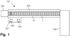
- FIG. 1 shows a simplified schematic view of an apparatus 101 for determining a mobility of ions with the above described method for determining a mobility of ions.
- This apparatus 101 includes an ion source 102 for ionising a sample including analytes to ions, wherein the analytes are atoms and/or compounds of interest and belong to N different ion species when being ionised to the ions.
- the apparatus 101 further includes an ion mobility separation cell 103 for separating the ions according to their mobility.
- This ion mobility separation cell 103 is fluidly coupled to the ion source 102 for receiving a stream of the ions ionised by the ion source 102.
- the ion source 102 is a continuous ion source. In other variants, however, the ion source 102 is a pulsed ion source.
- the apparatus 101 further includes an ion detector 104 for detecting the ions of the stream of ions after they have passed the ion mobility separation cell 103 and thus after they have been separated according to their mobility.
- the ion detector 104 is arranged downstream of the ion mobility separation cell 103 and is for providing a signal representing the detected ions.
- the ion detector 104 is a mass analyser, namely a time of flight mass analyser for obtaining mass spectra from the ions detected with the mass analyser.
- the apparatus 101 includes an ion mobility determination unit 105 for determining the mobility of the ions based on the signal obtained from the ion detector 104.
- the apparatus 101 includes a control unit 106 which is adapted to control the apparatus 101 to execute the method for determining the mobility of the ions.
- the apparatus 101 furthermore includes an ion guide assembly 1 according to the invention for modulating the stream of the ions according to a modulation function with the method according to the invention, wherein the stream of ions includes the at least N different ion species, wherein N is at least 1.
- This ion guide assembly 1 is marked in Figure 1 with a dashed rectangle.
- the ion guide assembly 1 includes an ion guide 10 which is arranged in the ion mobility determination cell 1 and forms an ion guide path, wherein the ions of the stream of ions are conveyable along the ion guide path in a conveying direction to form the stream of ions.
- the ion guide assembly 1 is operated such that the ions of the stream of ions is conveyed along the ion guide path, whereby the ions are separated according to their mobility.
- the ion guide 10 includes two printed circuit boards 11 which are identical to each other. These two printed circuit boards 11 are each arranged in a plane and are arranged parallel to each other at a distance from each other. Thus, pattern of electrodes including the conveying electrodes 230, 240 discussed later on in the context of Figure 2 are arranged on the two printed circuit boards 11, wherein the two printed circuit boards 11 are arranged parallel to each other such that the same electrodes of the two pattern of electrodes are arranged opposite to each other.
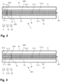
- Figure 2 shows a simplified schematic view of the ion guide assembly 1 according to the invention with the ion guide 10 forming an ion guide path. Thereby, for simplicity reasons, only one of the two printed circuit boards 11 of the ion guide 10 is shown in a top view in order to illustrate the design of the ion guide 10.
- the ions of the stream of ions are conveyable along the ion guide path in the conveying direction to form the stream of ions.
- the ion guide path is a spatial region between the two printed circuit boards 11, wherein the ions of the stream of ions move within the spatial region of the ion guide path when being conveyed along the ion guide path in the conveying direction.
- the course of the ion guide path and the conveying direction are indicated in Figure 2 with an arrow 50.
- Each one of the printed circuit boards 11 includes two elongated first DC confinement electrodes 16.1, 16.2 which are arranged parallel to each other. They extend along the ion guide path which runs between them. In operation of the ion guide 10, a first DC voltage is applied to these first DC confinement electrodes 16.1, 16.2 for maintaining the ions on the ion guide path.
- the ion guide assembly 1 includes a corresponding first DC voltage source which is however not shown here.
- each one of the printed circuit boards 11 includes two pairs of elongated second DC confinement electrodes 17.1, 17.2, 17.3, 17.4 which are arranged parallel to the first DC confinement electrodes 16.1, 16.2.
- a first pair of these second DC confinement electrodes 17.1, 17.2 reaches from the entrance end of the ion guide path very close to an ion gate position, while the second pair of these second DC confinement electrodes 17.3, 17.4 reaches from very close to the ion gate position to an exit end of the ion guide path.
- a second DC voltage is applied to these second DC confinement electrodes 17.1, 17.2, 17.3, 17.4 for maintaining the ions on the ion guide path.
- the second DC voltage is smaller than the first DC voltage such that the ions are maintained between the two printed circuit boards 11 and between the two first DC confinement electrodes 16.1, 16.2 in the spatial region of the ion guide path.
- the ion guide assembly 1 includes a corresponding second DC voltage source which is however not shown here.
- first and second DC confinement electrodes 16.1, 16.2, 17.1, 17.2, 17.3, 17.4 can be arranged is known in the art. Furthermore, some or all of these first and second DC confinement electrodes 16.1, 16.2, 17.1, 17.2, 17.3, 17.4 can be replaced with AC confinement electrodes to which radio frequency AC voltages are applied in order to hinder the ions of the stream of ions to get too close to these AC confinement electrodes. Such AC confinement electrodes are as well known in the art.
- the ion guide 10 includes an ion gate 12 which is arranged at the ion gate position on the ion guide path.
- This ion gate 12 is formed by two ion gate electrodes 220 which are each arranged on another one of the two circuit boards 11 opposite to each other.
- the ion gate electrodes 220 are elongated and oriented at an angle of 90° to the course of the ion guide path.
- the ion guide assembly 1 includes a gate voltage control circuitry 20 for applying a blocking voltage to the two ion gate electrodes 220.
- the ion gate 12 is switched to a closed state where it prevents the ions of the ion stream to pass the ion gate position when being conveyed along the ion guide path.
- the blocking voltage is a DC voltage.
- the blocking voltage is an AC voltage which is provided with opposite phases to the two ion gate electrodes 220.
- the ion gate 12 is operated in the blocking state in the same way as to the above described pairs of AC confinement electrodes are operated.
- the ion guide 10 further includes a first arrangement 13 of conveying electrodes 230 arranged along the ion guide path.
- This first arrangement 13 of conveying electrodes 230 extends over a first section of the ion guide path.
- the first section of the ion guide path starts at an entrance end of the first section of the ion guide path which is located at entrance end of the ion guide path, coinciding with the first end of the ion guide 10, and reaches downstream across the ion gate position to a transition position of the ion guide path.
- the first arrangement 13 of conveying electrodes 230 is adapted for generating first travelling waves having a first travelling wave amplitude and travelling along the entire first section of the ion guide path at a first travelling wave velocity for conveying the ions along the first section of the ion guide path.
- the first travelling waves have a wavelength.
- the entrance end of the first section of the ion guide path is located at a distance of one wavelength of the first travelling waves upstream from the ion gate position on the ion guide path, while the transition position is located at a distance of one wavelength of the first travelling waves downstream from the ion gate position on the ion guide path.
- the entrance end of the first section of the ion guide path is located further upstream of the ion gate position.
- the entrance end of the first section of the ion guide path is located 3 wavelengths of the first travelling waves, 18 wavelengths of the first travelling waves, 90 wavelengths of the first travelling waves and 1'000 wavelengths of the first travelling waves, respectively, upstream of the ion gate position.
- the first section of the ion guide path reaches from the ion gate position further downstream than one wavelength of the first travelling waves.
- the first section of the ion guide path reaches from the ion gate position 3 wavelengths of the first travelling waves, 18 wavelengths of the first travelling waves and 90 wavelengths of the first travelling waves, respectively, downstream.
- the transition position can be located at the downstream end of the first section of the ion guide path or may by somewhat upstream of the downstream end of the first section of the ion guide.
- the downstream end of the first section of the ion guide path is however at the transition position.
- the ion guide 10 furthermore includes a second arrangement 14 of conveying electrodes 240 arranged along the ion guide path.
- This second arrangement 14 of conveying electrodes 240 extends over a second section of the ion guide path, the second section of the ion guide path reaching from the transition position downstream to a downstream end of the second section.
- this downstream end of the second section is at the second end, also referred to as exit end, of the ion guide and thus coincides with the output end of the ion guide path.
- the second arrangement 14 of conveying electrodes 240 is adapted for generating second travelling waves having a second travelling wave amplitude and travelling along the entire second section of the ion guide path at a second travelling wave velocity for conveying the ions along the second section of the ion guide path.
- the second travelling waves have a wavelength.
- the second section of the ion guide path has a length of 1'000 wavelengths.
- Both the conveying electrodes 230 of the first arrangement 13 of conveying electrodes 230 and the conveying electrodes 240 of the second arrangement 14 of conveying electrodes 240 are arranged in three parallel lines along their respective section of the ion guide path. Thereby, a first one of these three parallel lines runs between one of the first DC confinement electrodes 16.1 and, upstream of the ion gate position, a first one of the first pair of the second DC confinement electrodes 17.1, and, downstream of the ion gate position, a first one of the second pair of the second DC confinement electrodes 17.3.
- a second one of the three parallel lines runs upstream of the ion gate position between the first pair of the second DC confinement electrodes 17.1, 17.2 and downstream of the ion gate position between the second pair of the second DC confinement electrodes 17.3, 17.4.
- the third one of the three parallel lines runs upstream of the ion gate position between the second one of the first pair of the second DC confinement electrodes 17.2 and the second one of the first DC confinement electrodes 16.2 and downstream of the ion gate position between the second one of the second pair of the second DC confinement electrodes 17.4 and the second one of the first DC confinement electrodes 16.2.
- the ion guide assembly 1 includes furthermore a low pressure chamber 18 surrounding the ion guide 10 for providing in the spatial region of the ion guide path a gas pressure which is reduced as compared to the atmospheric pressure.
- This low pressure chamber 18 comprises an inlet for inserting the ions into the low pressure chamber at the entrance end of the ion guide 10 and into the ion guide 10. Furthermore, the low pressure chamber 18 comprises an outlet for letting the ions out of the low pressure chamber 18 and out of the ion guide 10 at the exit end of the ion guide 10.
- the low pressure chamber 18 includes a pressure reduction unit 19 in the form of a vacuum pump for reducing and maintaining the reduced gas pressure in the low pressure chamber 18 and thus in the spatial region of the ion guide path 10.
- the low pressure chamber 18 may include a line for connecting the ion guide assembly 1 to a pressure reduction unit for reducing and maintaining the gas pressure in the low pressure chamber 18 and thus in the spatial region of the ion guide path 10.
- the ion guide assembly 1 is operated at a gas pressure of 3 mbar in the low pressure chamber 18.
- this gas pressure is in a range from 0.01 mbar to 1 bar, in a range from 0.01 mbar to 100 mbar, in a range from 0.01 mbar to 10 mbar, in a range 0.1 mbar to 1 bar, in a range from 0.1 mbar to 100 mbar, in a range from 0.1 mbar to 10 mbar, in a range from from 1 mbar to 1 bar, in a range from 1 mbar to 100 mbar and in a range from 1 mbar to 10 mbar.
- the gas pressure in the reduced may for example be 0.015 mbar, 0.09 mbar, 1.1 mbar, 10 mbar, 50 mbar, 100 mbar, 500 mbar or 900
- the ion guide assembly 1 further includes an AC voltage control circuitry 15 which is connected to the first arrangement 13 of conveying electrodes 230 for supplying the conveying electrodes 230 of the first arrangement 13 of conveying electrodes 230 with AC voltages for generating the first travelling waves for conveying the ions of the stream of ions downstream of the ion gate 12 along the first section of the ion guide path in the conveying direction away from the ion gate 12.
- This AC voltage control circuitry 15 is as well connected to the second arrangement 14 of conveying electrodes 240 for supplying the conveying electrodes 240 of the second arrangement 14 of conveying electrodes 240 with AC voltages for generating the second travelling waves for conveying the ions along the second section of the ion guide path in the conveying direction away from the ion gate 12 to the second end of the ion guide.
- the AC voltage control circuitry 15 provides a sinusoidal AC voltage at a frequency of 70 kHz and a peak-to-peak voltage of 20 V.
- the frequency can be in the range from 60 kHz to 80 kHz, while the peak-to-peak voltage is in the range from 10 V to 30 V.
- the frequency of the sinusoidal AC voltage may be lower or higher.
- the radio frequency range like for example 100 kHz, 150 kHz or even more than 500 kHz, like 5 MHz or 50 MHz are possible, too.
- lower frequencies like for example 10 kHz or 40 kHz are possible, too.
- peak-to-peak voltages are chosen such that when the AC voltages are applied to the first and second conveying electrodes, the maximum strength of the electric field generated by the conveying electrodes is in a range between 1 V/mm and 5'000 V/mm.
- the shape of the AC voltages provided by the AC voltage control circuitry 15 differ from a sinusoidal AC voltage.
- the AC voltages may follow a periodic curve which is different from a sine curve.
- the periodic curve may be a continuously differentiable curve or may be a curve providing kinks and thus provide positions where it is not differentiable.
- the AC voltages may thus for example be periodical, rectangular shaped DC voltage pulses.
- the AC voltage control circuitry 15 is connected to the conveying electrodes 230, 240 of the first and second arrangement 13, 14 of conveying electrodes 230, 240 such that the first and second travelling waves, respectively, are generated. How this is achieved is explained in great detail in EP 3 561 853 A1 of Tofwerl ⁇ AG. In the present embodiment shown in Figure 2 , for both the first and the second arrangement 13, 14 of conveying electrodes 230, 240, the respective conveying electrodes 230, 240 are arranged in a succession of each other along the ion guide path.
- the AC voltage control circuitry 15 is a unit which is separate from the ion guide 10.
- each one of the respective conveying electrodes 230, 240 is connected to each one of the respective conveying electrodes 230, 240 for supplying each one of the respective conveying electrodes 230, 240 with the respective AC voltage having the frequency of 70 kHz and the peak-to-peak amplitude of 20 Volt.
- the AC voltage has a phase decreased by an amount of 120° as compared to for the respective preceding neighbouring respective conveying electrode 230, 240.
- the first travelling waves and the second travelling waves are generated along the ion guide path.
- the first travelling waves and the second travelling waves are AC potential waves. Due to the phase difference of 120° between the respective conveying electrodes 230, 240, the first travelling waves generated in the first section of the ion guide path have a wavelength which extends over three neighbouring conveying electrodes 230 of the first arrangement 13 of conveying electrodes 230, while the second travelling waves generated in the second section of the ion guide path have a wavelength which extends over three neighbouring conveying electrodes 240 of the second arrangement 14 of conveying electrodes 240.
- the first travelling waves move in conveying direction along the entire first section of the ion guide path and the second travelling waves move in conveying direction along the entire second section of the ion guide path, respectively.
- the first travelling waves and the second travelling waves are felt as a driving force that conveys the ions of the stream of ions along the ion guide path in the conveying direction.
- the first travelling waves and the second travelling waves are chosen to be in phase at the transition position.
- the invention is not limited to this particular arrangement of how the AC voltages are supplied to the conveying electrodes 230, 240 of the first arrangement 13 of conveying electrodes 230 and the second arrangement 14 of conveying electrodes 240, respectively.
- Other options are readily available to the person skilled in the art.
- the phase difference between the neighbouring conveying electrodes 230, 240 is chosen to be smaller than 120°.
- the phase difference may be chosen to be 90° or 60°.
- Other options of how the AC voltages can be supplied to the conveying electrodes 230, 240 of the first arrangement 13 of conveying electrodes 230 and the second arrangement 14 of conveying electrodes 240, respectively, are explained in EP 3 561 853 A1 of Tofwerl ⁇ AG .
- the first arrangement 13 of conveying electrodes 230 are arranged more compact along the ion guide path than the conveying electrodes 240 of the second arrangement 14 of conveying electrodes 240 are arranged along the ion guide path.
- a length of each of the conveying electrodes 230 of the first arrangement 13 of conveying electrodes 230 measured along the ion guide path at a position of the respective conveying electrode 230 on the ion guide path is 1.0 mm.
- a length of each of the conveying electrodes 240 of the second arrangement 14 of conveying electrodes 240 measured along the ion guide path at a position of the respective conveying electrode 240 on the ion guide path however is 2.0 mm.
- the length of the conveying electrodes 230 of the first arrangement 13 of conveying electrodes 230 measured along the ion guide path is half of the length of the conveying electrodes 240 of the second arrangement 14 of conveying electrodes 240 measured along the ion guide path at a position of the respective conveying electrode 240 on the ion guide path. Furthermore, a spacing between the conveying electrodes 230 of the first arrangement 13 of conveying electrodes 230 measured along the ion guide path is 0.1 mm, while a spacing between the conveying electrodes 240 of the second arrangement 14 of conveying electrodes 240 measured along the ion guide path is 0.2 mm.
- the spacing between the conveying electrodes 230 of the first arrangement 13 of conveying electrodes 230 measured along the ion guide path is only half as much as the spacing between the conveying electrodes 240 of the second arrangement 14 of conveying electrodes 240 measured along the ion guide path.
- the conveying electrodes 230 of the first arrangement 13 of conveying electrodes 230 are arranged along the ion guide path to extend only 50% as much along the ion guide path as compared to how the conveying electrodes 240 of the second arrangement 14 of conveying electrodes 240 are arranged to extend along the ion guide path.
- the first travelling waves have a wavelength which is half the wavelength of the second travelling waves, and the first travelling wave velocity is half of the second travelling wave velocity.
- the second travelling wave velocity is by a factor of two higher than the first travelling wave velocity while the second travelling wave amplitude is the same as the first travelling wave amplitude.
- the wavelength of the first travelling waves is 3.3 mm, while the wavelength of the second travelling waves is 6.6 mm. Since the AC voltages applied to the conveying electrodes 230, 240 have a frequency of 70 kHz, the first travelling wave velocity is 231 m/s while the second travelling wave velocity is 462 m/s.
- this arrangement has the effect that the mobility of the ions of most ion species in the mass-to-charge range from 100 u/e to 250 u/e is such that the ions have an average velocity in the first section of the ion guide path which is between 70% and 100% of the first travelling wave velocity, while in the second section of the ion guide path, they have an average velocity which is slower than in the first section of the ion guide path.
- the average velocity of the ions in the stream of ions in the second section of the ion guide path is strongly dependent on the mobility of the respective ion.
- the average velocity in the second section of the ion guide path is often fairly close to their average velocity in the first section of the ion guide path, while for heavier ions with a mass-to-charge ratio of about 250 u/e, the average velocity in the second section of the ion guide path may easily become slower by a factor of 3 or 4 as compared to their average velocity in the first section of the ion guide path.
- an optimal separation of the ions according to their mobility can be achieved by conveying the ions along the second section of the ion guide path.
- the conditions are such that the ions are conveyed along the first section of the ion guide path past the ion gate in the open state of the ion gate uniformly and almost independent of their mobility.
- the apparatus 101 is used to determine a mobility of the ions obtained from a gaseous sample by determining the mobility of the ions with the above described method for determining the mobility of the ions.
- the gaseous sample is fed to the ion source 102 and ionised with the ion source 102.
- the gaseous sample includes 15 different atoms and/or compounds of interest and thus 15 analytes. In the present example, these analytes have masses in the range from 100 u to 250 u.
- the ions obtained from the 15 analytes belong to 15 different ion species having a mass-to-charge ratio in the range from 100 u/e to 250 u/e.
- the sample can be of a different form than a gaseous form. Furthermore, it can comprise less than 15 atoms and/or compounds of interest or more than 15 atoms and/or compounds of interest and thus more or less than 15 analytes.
- the ions obtained from the analytes belong to different ion species having a mass-to-charge ratios within, above or below the range from 100 u/e to 250 u/e.
- the ions obtained from the sample are transferred into the ion mobility separation cell 103 and into the ion guide 10.
- the ion source 102 is a continuous ion source, in the present example, a continuous stream of ions with ions of the 15 different ion species having a mass-to-charge ratio in the range from 100 u/e to 250 u/e is inserted into the ion guide 10.
- This stream of ions is then modulated with the ion gate 12 according to a modulation function with the method according to the invention.
- the ions of the stream of ions are passed along the second section of the ion guide path and thus passed through an ion mobility separation cell 103 for separating the ions in the stream of ions according to their mobility.
- the ions having passed the ion mobility separation cell 103 are detected with the ion detector 104 which provides a signal representing the detected ions and the mobility of the ions is determined with the ion mobility determination unit 105 based on the signal obtained from the ion detector 104.
- the stream of ions includes N different ion species wherein N is equal 15.
- N can be 1, 2, 3, 4, 8, 10, 50 or more.
- a ratio A is the average velocity of the ions of the respective ion species in the first section of the ion guide path divided by the first travelling wave velocity.
- a ratio B is the average velocity of the ions of the respective ion species in the second section of the ion guide path divided by the second travelling wave velocity. Due to the above described characteristics of the ion guide assembly 1 and the parameters at which the ion guide assembly 1 is operated, for each ion species of the at least N different ion species, the ratio A is larger than twice the ratio B.
- the ratio A is larger than the ratio B, larger than the ratio B multiplied by a factor of 1.1 and even larger than the ratio B multiplied by the factor of 2.
- the ratio A is smaller than the ratio B multiplied by the factor of 100. Consequently, the ion guide 10 is operated in the first section of the ion guide path in conditions where the first travelling waves have a more trapping effect on the ions of the at least N ion species than the second travelling waves the second section of the ion guide path have.
- the ions of the at least N ion species experience the first travelling waves more like potential wells than they experience the second travelling waves in the second section of the ion guide path. They are conveyed in the first section of the ion guide path with an average velocity between 70% and 100% of the first travelling wave velocity. Consequently, the ions of the at least N ion species are conveyed more independent of their mobility and thus more uniformly along the first section of the ion guide path than they are conveyed along the second section of the ion guide path. In other words, in the first section of the ion guide, ions having a lower mobility are conveyed at a more similar or even the same speed as ions having a higher mobility.
- the fraction of ions having a lower mobility which makes it past the ion gate 12 before the ion gate 12 is switched to the closed state again is closer to or even the same as the fraction of ions having a higher mobility which makes it past the ion gate 12 before the ion gate is switched to the closed state again. Therefore, in the ion guide 10, the stream of ions is modulated very accurately according to a modulation function, whereafter the ions are separated according to their mobility.
- the modulation function according to which the stream of ions is modulated is a binary function in the form of a pseudorandom sequence.
- An autocorrelation of this modulation function is a two-valued function having a peak at zero and a constant value at all other values.
- a correlation of the modulation function and the signal obtained from the ion detector 104 is calculated with a calculation unit 107.
- This calculation unit 107 is part of the ion mobility determination unit 105.
- This correlation provides in the first place the time distribution of the ions required for passing the ion mobility separation cell 103. Thus, the correlation is the drift time distribution and thus the mobility of the ions.
- the correlation is then scaled as known in the art by the ion mobility determination unit 105 according to reference standards.
- the ion guide assembly 1 includes a control unit 2 adapted to control the ion guide assembly 1 such that the first travelling wave amplitude, the first travelling wave velocity, the second travelling wave amplitude and the second travelling wave velocity are chosen such that for each ion species of the at least N different ion species, the ratio A is larger than the ratio B.
- the control unit 2 of the ion guide assembly 1 is controlled by the apparatus control unit 106 in order to control the ion guide assembly 1 for controlling the apparatus 101 to execute the method for determining the mobility of the ions.
- FIG 3 shows a simplified schematic view of another ion guide assembly 301 according to the invention for executing the method according to the invention.
- This ion guide assembly 301 is to a large extend the same as the ion guide assembly 1 shown in Figure 2 .
- the elements of the ion guide assembly 301 shown in Figure 3 which are the same as the ones of the ion guide assembly 1 of Figure 2 are labelled with the same reference numbers. Elements which differ from the elements of the ion guide assembly 1 of Figure 2 however are labelled with a different reference number.
- the conveying electrodes 330 of the first arrangement 313 of conveying electrodes 330 have a length of 2.0 mm measured along the ion guide path at a position of the respective conveying electrode 330 on the ion guide path.
- the length of the conveying electrodes 330 of the first arrangement 313 of conveying electrodes 330 measured along the ion guide path is the same as the length of the conveying electrodes 240 of the second arrangement 14 of conveying electrodes 240 measured along the ion guide path at a position of the respective conveying electrode 240 on the ion guide path.
- the gaps between the conveying electrodes 330 of the first arrangement 313 of conveying electrodes 330 have a length of 0.2 mm measured along the ion guide path at their respective position which is the same as the gaps between the conveying electrodes 240 of the second arrangement 14 of conveying electrodes 240.
- the AC voltage control circuitry 15 is adapted to apply AC voltages to the first arrangement 313 of conveying electrodes 330 which differ from the AC voltages applied to the second arrangement 14 of conveying electrodes 240 in that it has a frequency which is only 35 kHz and which is thus half of the frequency of the AC voltages applied to the second arrangement 14 of conveying electrodes 240.
- the first travelling waves have the same wavelength as the second travelling waves but have a first travelling wave velocity which is half the second travelling wave velocity.
- the conditions experienced by the ions in the first section of the ion guide path and in the second section of the ion guide path are nearly the same as the ones experienced in the ion guide 10 of the ion guide assembly 1 shown in Figure 2 .
- the slopes of the first travelling waves are less steep and, measured in millimeters, the first section of the ion guide path has double the length of the first section of the ion guide path of the ion guide assembly 1 shown in Figure 2 .
- the ratio A is still larger than twice the ratio B.
- a method and an ion guide assembly are provided that enable modulating a stream of ions more precisely according to a modulation function in an ion guide.
Landscapes
- Chemical & Material Sciences (AREA)
- Analytical Chemistry (AREA)
- Physics & Mathematics (AREA)
- Spectroscopy & Molecular Physics (AREA)
- Chemical Kinetics & Catalysis (AREA)
- Electrochemistry (AREA)
- Health & Medical Sciences (AREA)
- Life Sciences & Earth Sciences (AREA)
- Biochemistry (AREA)
- General Health & Medical Sciences (AREA)
- General Physics & Mathematics (AREA)
- Immunology (AREA)
- Pathology (AREA)
- Other Investigation Or Analysis Of Materials By Electrical Means (AREA)
Claims (15)
- Ein Verfahren zum Modulieren eines Ionenstroms gemäß einer Modulationsfunktion in einem lonenleiter (10), wobei der Ionenstrom mindestens N verschiedene Ionenarten umfasst, wobei N mindestens 1 ist,wobei der lonenleiter (10) einen lonenleiterpfad bildet, wobei die Ionen des Ionenstroms entlang des lonenleiterpfads in einer Förderrichtung befördert werden, um den Ionenstrom zu bilden,wobei der lonenleiter (10) ein Ionentor (12) umfasst, das an einer Ionentorposition auf dem lonenleiterpfad angeordnet ist, wobei das Ionentor (12) so ausgelegt ist, dass es einen offenen Zustand bereitstellt, um den Ionen zu ermöglichen, die Ionentorposition zu passieren, wenn sie entlang des lonenleiterpfads befördert werden, und dass es einen geschlossenen Zustand bereitstellt, um zu verhindern, dass die Ionen die Ionentorposition passieren,wobei der lonenleiter (10) eine erste Anordnung (13, 313) von Förderelektroden (230, 330) umfasst, die entlang des lonenleiterpfads angeordnet sind, wobei sich die erste Anordnung (13, 313) von Förderelektroden (230, 330) über einen ersten Abschnitt des lonenleiterpfads erstreckt, wobei der erste Abschnitt des lonenleiterpfads von mindestens die Ionentorposition stromabwärts bis zu mindestens einer Übergangsposition auf dem lonenleiterpfad erstreckt, wobei die erste Anordnung (13, 313) von Förderelektroden (230, 330) zum Erzeugen erster Wanderwellen mit einer ersten Wanderwellenamplitude und zum Wandern entlang des ersten Abschnitts des lonenleiterpfads mit einer ersten Wanderwellengeschwindigkeit zum Fördern der Ionen entlang des ersten Abschnitts des lonenleiterpfads angepasst ist,wobei der lonenleiter (10) eine zweite Anordnung (14) von Förderelektroden (240) umfasst, die entlang des lonenleiterpfads angeordnet sind, wobei sich die zweite Anordnung (14) von Förderelektroden (240) über einen zweiten Abschnitt des lonenleiterpfads erstreckt, wobei der zweite Abschnitt des lonenleiterpfads sich von der Übergangsposition stromabwärts erstreckt, wobei die zweite Anordnung (14) von Förderelektroden (240) zum Erzeugen zweiter Wanderwellen mit einer zweiten Wanderwellenamplitude und zum Wandern entlang des zweiten Abschnitts des lonenleiterpfads mit einer zweiten Wanderwellengeschwindigkeit zum Fördern der Ionen entlang des zweiten Abschnitts des lonenleiterpfads angepasst ist,wobei gemäß dem Verfahren der Ionenstrom mit dem Ionentor (12) gemäß der Modulationsfunktion moduliert wird und Wechselspannungen an die erste Anordnung (13, 313) von Förderelektroden (230, 330) zur Erzeugung der ersten Wanderwellen und an die zweite Anordnung (14) von Förderelektroden (240) zum Erzeugen der zweiten Wanderwellen zum Fördern der Ionen stromabwärts des Ionentors (12) entlang des ersten Abschnitts und des zweiten Abschnitts des Ionenleiterpfads in der Förderrichtung weg von dem Ionentor (12) angelegt werden,wobei für jede Ionenart der mindestens N verschiedenen Ionenarten ein Verhältnis A die durchschnittliche Geschwindigkeit der Ionen der jeweiligen Ionenart in dem ersten Abschnitt des Ionenleiterpfads geteilt durch die erste Wanderwellengeschwindigkeit ist,wobei für jede Ionenart der mindestens N verschiedenen Ionenarten ein Verhältnis B die durchschnittliche Geschwindigkeit der Ionen der jeweiligen Ionenart in dem zweiten Abschnitt des Ionenleiterpfads geteilt durch die zweite Wanderwellengeschwindigkeit ist,wobei die erste Wanderwellenamplitude, die erste Wanderwellengeschwindigkeit, die zweite Wanderwellenamplitude und die zweite Wanderwellengeschwindigkeit so gewählt werden, dass für jede Ionenart der mindestens N verschiedenen Ionenarten das Verhältnis A größer ist als das Verhältnis B.
- Das Verfahren nach Anspruch 1, dadurch gekennzeichnet, dass die erste Wanderwellenamplitude, die erste Wanderwellengeschwindigkeit, die zweite Wanderwellenamplitude und die zweite Wanderwellengeschwindigkeit so gewählt werden, dass für jede Ionenart der mindestens N verschiedenen Ionenarten das Verhältnis A mindestens das mit dem Faktor 1.1 multiplizierte Verhältnis B, insbesondere mindestens das mit dem Faktor 2 multiplizierte Verhältnis B, ist
- Das Verfahren nach Anspruch 1 oder 2, dadurch gekennzeichnet, dass die zweite Wanderwellengeschwindigkeit höher ist als die erste Wanderwellengeschwindigkeit.
- Das Verfahren gemäß einem der Ansprüche 1 bis 3, dadurch gekennzeichnet, dass die erste Wanderwellenamplitude und die erste Wanderwellengeschwindigkeit so gewählt werden, dass für jede Ionenart der mindestens N verschiedenen Ionenarten die Ionen der jeweiligen Ionenart in dem ersten Abschnitt des Ionenleiterpfads mit einer Durchschnittsgeschwindigkeit befördert werden, die höher als 70 % die erste Wanderwellengeschwindigkeit ist.
- Das Verfahren nach einem der Ansprüche 1 bis 4, dadurch gekennzeichnet, dass der Ionenleiter (10) bei einem Gasdruck im Bereich von 0,01 mbar bis 1 bar, von 0,01 mbar bis 100 mbar oder von 0,01 mbar bis 10 mbar, vorzugsweise 0,1 mbar bis 1 bar, von 0,1 mbar bis 100 mbar oder von 0,1 mbar bis 10 mbar, besonders bevorzugt von 1 mbar bis 1 bar, von 1 mbar bis 100 mbar oder von 1 mbar bis 10 mbar, ist.
- Das Verfahren nach einem der Ansprüche 1 bis 5, dadurch gekennzeichnet, dass N mindestens 2, vorzugsweise mindestens 5, besonders bevorzugt mindestens 10 beträgt.
- Das Verfahren gemäß einem der Ansprüche 1 bis 6, dadurch gekennzeichnet, dass die ersten Wanderwellen eine Wellenlänge aufweisen und die Übergangsposition in einem Abstand von mindestens einer Wellenlänge der ersten Wanderwellen stromabwärts von der Ionentorposition auf dem Ionenleiterpfad angeordnet ist.
- Das Verfahren gemäß einem der Ansprüche 1 bis 7, dadurch gekennzeichnet, dass der erste Abschnitt des Ionenleiterpfads von der Ionentorposition stromaufwärts zu einem Eingangsende des ersten Abschnitts des Ionenleiterpfads reicht.
- Das Verfahren nach Anspruch 8, dadurch gekennzeichnet, dass die ersten Wanderwellen eine Wellenlänge aufweisen und das Eingangsende des ersten Abschnitts des Ionenleiterpfads in einem Abstand von mindestens einer Wellenlänge der ersten Wanderwellen stromaufwärts von der Ionentorposition auf dem Ionenleiterpfad angeordnet ist.
- Ein Verfahren zur Bestimmung der Mobilität von Ionen, wobei ein Ionenstrom mit dem Verfahren gemäß einem der Ansprüche 1 bis 9 gemäß einer Modulationsfunktion moduliert wird und anschließend durch eine Ionenmobilitätsseparierungszelle (103) geleitet wird, wobei die Ionen, die die Ionenmobilitätsseparierungszelle (103) passiert haben, mit einem Ionendetektor (104) detektiert werden, der ein Signal bereitstellt, das die detektierten Ionen darstellt, und die Mobilität der Ionen auf der Grundlage des von dem Ionendetektor (104) erhaltenen Signals bestimmt wird.
- Das Verfahren nach Anspruch 10, dadurch gekennzeichnet, dass der zweite Abschnitt des Ionenleiterpfads durch die Ionenmobilitätsseparierungszelle (103) verläuft und die Ionen entsprechend ihrer Mobilität separiert werden, wenn sie entlang des zweiten Abschnitts des Ionenleiterpfads befördert werden.
- Das Verfahren nach Anspruch 10 oder 11, dadurch gekennzeichnet, dass die Mobilität der Ionen durch Berechnung einer Korrelation der Modulationsfunktion und des von dem Ionendetektor (104) erhaltenen Signals erhalten wird, wobei eine Autokorrelation der Modulationsfunktion eine zweiwertige Funktion ist.
- Eine Ionenleiteranordnung (1, 301) zum Modulieren eines Ionenstroms gemäß einer Modulationsfunktion mit dem Verfahren gemäß einem der Ansprüche 1 bis 9, wobei der Ionenstrom mindestens N verschiedene Ionenarten umfasst, wobei N mindestens 1 ist, wobei die Ionenleiteranordnung (1, 301) einen Ionenleiter (10) umfasst, der einen Ionenleiterpfad bildet, wobei die Ionen des Ionenstroms entlang des Ionenleiterpfads in einer Förderrichtung befördert werden können, um den Ionenstrom zu bilden,a) wobei der Ionenleiter (10) ein Ionentor (12) umfasst, das an einer Ionentorposition auf dem Ionenleiterpfad angeordnet ist, wobei das Ionentor (12) so ausgelegt ist, dass es einen offenen Zustand bereitstellt, um den Ionen zu ermöglichen, die Ionentorposition zu passieren, wenn sie entlang des Ionenleiterpfads befördert werden, und einen geschlossenen Zustand bereitstellt, um zu verhindern, dass die Ionen die Ionentorposition passieren,b) wobei der Ionenleiter (10) eine erste Anordnung (13, 313) von Förderelektroden (230, 330) umfasst, die entlang des Ionenleiterpfads angeordnet sind, wobei sich die erste Anordnung (13, 313) von Förderelektroden (230, 330) über einen ersten Abschnitt des Ionenleiterpfads erstreckt, wobei der erste Abschnitt des Ionenleiterpfads von mindestens der Ionentorposition stromabwärts bis mindestens zu einer Übergangsposition auf dem Ionenleiterpfad erstreckt, wobei die erste Anordnung (13, 313) von Förderelektroden (230, 330) zum Erzeugen erster Wanderwellen mit einer ersten Wanderwellenamplitude und zum Wandern entlang des ersten Abschnitts des Ionenleiterpfads mit einer ersten Wanderwellengeschwindigkeit zum Fördern der Ionen entlang des ersten Abschnitts des Ionenleiterpfads angepasst ist,c) wobei der Ionenleiter (10) eine zweite Anordnung (14) von Förderelektroden (240) umfasst, die entlang des Ionenleiterpfads angeordnet sind, wobei sich die zweite Anordnung (14) von Förderelektroden (240) über einen zweiten Abschnitt des Ionenleiterpfads erstreckt, wobei der zweite Abschnitt des Ionenleiterpfads von der Übergangsposition stromabwärts erstreckt, wobei die zweite Anordnung (14) von Förderelektroden (240) zum Erzeugen zweiter Wanderwellen mit einer zweiten Wanderwellenamplitude und zum Wandern entlang des zweiten Abschnitts des Ionenleiterpfads mit einer zweiten Wanderwellengeschwindigkeit zum Fördern der Ionen entlang des zweiten Abschnitts des Ionenleiterpfads angepasst ist,wobei die Ionenleiteranordnung (1, 310) mindestens eine Wechselspannungsteuerungsschaltung (15, 315) umfasst, die mit der ersten Anordnung (13, 313) von Förderelektroden (230, 330) verbunden werden kann, um die Förderelektroden (230, 330) der der ersten Anordnung (13, 313) von Förderelektroden (230, 330) mit Wechselspannungen zur Erzeugung der ersten Wanderwellen zum Fördern der Ionen stromabwärts des Ionentors (12) entlang des ersten Abschnitts des Ionenleiterpfads in Förderrichtung weg vom Ionentor (12) zu versorgen, und die mit der zweiten Anordnung (14) von Förderelektroden (240) verbunden werden kann, um die Förderelektroden (240) der zweiten Anordnung (14) von Förderelektroden (240) mit Wechselspannungen zu versorgen, um die zweiten Wanderwellen zu erzeugen, um die Ionen entlang des zweiten Abschnitts des Ionenleiterpfads in die Förderrichtung weg von dem Ionentor (12) zu fördern,wobei die Ionenleiteranordnung (1, 301) eine Steuereinheit (2) umfasst, die so eingerichtet ist, dass sie die Ionenleiteranordnung (1, 301) so steuert, dass die erste Wanderwellenamplitude, die erste Wanderwellengeschwindigkeit, die zweite Wanderwellenamplitude und die zweite Wanderwellengeschwindigkeit so gewählt werden, dass für jede Ionenart der mindestens N verschiedenen Ionenarten ein Verhältnis A größer ist als ein Verhältnis B, wobei das Verhältnis A für jede Ionenart der mindestens N verschiedenen Ionenarten die durchschnittliche Geschwindigkeit der Ionen der jeweiligen Ionenart in dem ersten Abschnitt des Ionenleiterpfads geteilt durch die erste Wanderwellengeschwindigkeit ist und wobei das Verhältnis B für jede Ionenart der mindestens N verschiedenen Ionenarten die durchschnittliche Geschwindigkeit der Ionen der jeweiligen Ionenart in dem zweiten Abschnitt des Ionenleiterpfads geteilt durch die zweite Wanderwellengeschwindigkeit ist.
- Die Ionenleiteranordnung (1, 301) nach Anspruch 13, dadurch gekennzeichnet, dass die mindestens eine Wechselspannungsteuerungsschaltung (15, 315) mit der ersten Anordnung (13, 313) von Förderelektroden (230, 330) verbunden ist, um die Förderelektroden (230, 330) der ersten Anordnung (13, 313) von Förderelektroden (230, 330) mit Wechselspannungen zur Erzeugung der ersten Wanderwellen zum Fördern der Ionen stromabwärts des Ionentors (12) entlang des ersten Abschnitts des Förderwegs in Förderrichtung weg vom Ionentor (12) und mit die zweite Anordnung (14) von Förderelektroden (240) verbunden ist, um die Förderelektroden (240) der zweiten Anordnung (14) von Förderelektroden (240) mit Wechselspannungen zu versorgen, um die zweiten Wanderwellen zu erzeugen, um die Ionen entlang des zweiten Abschnitts des Ionenleiterpfads in der Förderrichtung weg von dem Ionentor (12) zu fördern.
- Eine Vorrichtung (101) zur Bestimmung der Mobilität von Ionen mit dem Verfahren gemäß einem der Ansprüche 10 bis 12, dadurch gekennzeichnet, dass die Vorrichtung (101) Folgendes umfasst:a) eine Ionenleiteranordnung (1, 301) gemäß Anspruch 13 oder 14 zur Modulation eines Ionenstroms gemäß einer Modulationsfunktion mit dem Verfahren gemäß einem der Ansprüche 1 bis 9,b) eine Ionenmobilitätsseparierungszelle (103) zum Separieren der Ionen in dem Ionenstrom gemäß ihrer Mobilität, nachdem der Ionenstrom gemäß der Modulationsfunktion moduliert worden ist, undc) einen Ionendetektor (104) zum Detektieren der Ionen, nachdem sie die Ionenmobilitätsseparierungszelle (103) passiert haben, und zum Bereitstellen eines Signals, das die detektierten Ionen darstellt, undd) eine Ionenbeweglichkeitsbestimmungseinheit (105) zum Bestimmen der Mobilität der Ionen auf der Grundlage des von dem Ionendetektor (104) erhaltenen Signals.
Priority Applications (1)
| Application Number | Priority Date | Filing Date | Title |
|---|---|---|---|
| EP21176300.8A EP4095525B1 (de) | 2021-05-27 | 2021-05-27 | Verfahren und ionenführungsanordnung zur modulation eines ionenstroms |
Applications Claiming Priority (1)
| Application Number | Priority Date | Filing Date | Title |
|---|---|---|---|
| EP21176300.8A EP4095525B1 (de) | 2021-05-27 | 2021-05-27 | Verfahren und ionenführungsanordnung zur modulation eines ionenstroms |
Publications (2)
| Publication Number | Publication Date |
|---|---|
| EP4095525A1 EP4095525A1 (de) | 2022-11-30 |
| EP4095525B1 true EP4095525B1 (de) | 2024-12-18 |
Family
ID=76159377
Family Applications (1)
| Application Number | Title | Priority Date | Filing Date |
|---|---|---|---|
| EP21176300.8A Active EP4095525B1 (de) | 2021-05-27 | 2021-05-27 | Verfahren und ionenführungsanordnung zur modulation eines ionenstroms |
Country Status (1)
| Country | Link |
|---|---|
| EP (1) | EP4095525B1 (de) |
Families Citing this family (2)
| Publication number | Priority date | Publication date | Assignee | Title |
|---|---|---|---|---|
| EP4614140A1 (de) | 2024-03-05 | 2025-09-10 | Tofwerk AG | Verfahren und vorrichtung zur bestimmung der mobilität von ionen |
| CN119153310B (zh) * | 2024-08-20 | 2025-10-10 | 湖南大学 | 一种用于离子迁移谱仪器的双路行波离子迁移管装置 |
Family Cites Families (7)
| Publication number | Priority date | Publication date | Assignee | Title |
|---|---|---|---|---|
| GB2391697B (en) | 2002-05-30 | 2004-07-28 | Micromass Ltd | Mass spectrometer |
| US6791078B2 (en) * | 2002-06-27 | 2004-09-14 | Micromass Uk Limited | Mass spectrometer |
| EP2587259A1 (de) | 2011-10-26 | 2013-05-01 | Tofwerk AG | Verfahren und Vorrichtung zur Bestimmung der Mobilität von Ionen |
| US8835839B1 (en) | 2013-04-08 | 2014-09-16 | Battelle Memorial Institute | Ion manipulation device |
| GB201614540D0 (en) * | 2016-08-26 | 2016-10-12 | Micromass Ltd | Controlling ion temperature in an ion guide |
| EP3561853A1 (de) | 2018-04-26 | 2019-10-30 | Tofwerk AG | Ionenführungsanordnung |
| GB201913378D0 (en) * | 2019-09-17 | 2019-10-30 | Micromass Ltd | Ion mobility separation device |
-
2021
- 2021-05-27 EP EP21176300.8A patent/EP4095525B1/de active Active
Also Published As
| Publication number | Publication date |
|---|---|
| EP4095525A1 (de) | 2022-11-30 |
Similar Documents
| Publication | Publication Date | Title |
|---|---|---|
| US12422402B2 (en) | Methods and apparatus for trapping and accumulation of ions | |
| EP2160751B1 (de) | Ionentransporteinrichtung und betriebsarten dafür | |
| EP2170491B1 (de) | Verfahren und vorrichtung zur digitalen trennung auf basis der mobilitätsdifferenz von ionen | |
| EP4095525B1 (de) | Verfahren und ionenführungsanordnung zur modulation eines ionenstroms | |
| US12163920B2 (en) | Systems and methods for two-dimensional mobility based filtering of ions | |
| CA2770819A1 (en) | Coupling ion differential mobility based ambient pressure ion pre-filtering and ion focusing for a portable mass spectrometer | |
| US9734998B2 (en) | AC gate ion filter method and apparatus | |
| US20250076250A1 (en) | Laterally-extended trapped ion mobility spectrometer | |
| KR20140056175A (ko) | Faims 셀이 삽입된 이온 이동성 분광 측정기 장치 | |
| US7399959B2 (en) | Method and apparatus for enhanced ion based sample filtering and detection | |
| EP3561853A1 (de) | Ionenführungsanordnung | |
| KR101496176B1 (ko) | 결합 이온 게이트 및 변형기 | |
| WO2006084363A1 (en) | Apparatus and method for an electro-acoustic ion transmittor | |
| US11605532B2 (en) | Method and ion guide assembly for modulating a stream of ions | |
| US10458946B2 (en) | Ion selecting device for identification of ions in gaseous media | |
| KR20070109999A (ko) | 분석장치 | |
| US20110139972A1 (en) | Methods and Apparatus for Providing FAIMS Waveforms Using Solid-State Switching Devices | |
| US20210285913A1 (en) | Multi-gate multi-frequency filter for ion mobility isolation | |
| US20260128269A1 (en) | Ion Guide with Switchable Operation Modes | |
| JP7503949B2 (ja) | イオン移動度分析装置およびイオン移動度分析方法 | |
| EP4614140A1 (de) | Verfahren und vorrichtung zur bestimmung der mobilität von ionen | |
| WO2026027893A1 (en) | Ion separators |
Legal Events
| Date | Code | Title | Description |
|---|---|---|---|
| PUAI | Public reference made under article 153(3) epc to a published international application that has entered the european phase |
Free format text: ORIGINAL CODE: 0009012 |
|
| STAA | Information on the status of an ep patent application or granted ep patent |
Free format text: STATUS: THE APPLICATION HAS BEEN PUBLISHED |
|
| AK | Designated contracting states |
Kind code of ref document: A1 Designated state(s): AL AT BE BG CH CY CZ DE DK EE ES FI FR GB GR HR HU IE IS IT LI LT LU LV MC MK MT NL NO PL PT RO RS SE SI SK SM TR |
|
| RBV | Designated contracting states (corrected) |
Designated state(s): AL AT BE BG CH CY CZ DE DK EE ES FI FR GB GR HR HU IE IS IT LI LT LU LV MC MK MT NL NO PL PT RO RS SE SI SK SM TR |
|
| STAA | Information on the status of an ep patent application or granted ep patent |
Free format text: STATUS: REQUEST FOR EXAMINATION WAS MADE |
|
| 17P | Request for examination filed |
Effective date: 20230117 |
|
| GRAP | Despatch of communication of intention to grant a patent |
Free format text: ORIGINAL CODE: EPIDOSNIGR1 |
|
| STAA | Information on the status of an ep patent application or granted ep patent |
Free format text: STATUS: GRANT OF PATENT IS INTENDED |
|
| INTG | Intention to grant announced |
Effective date: 20240820 |
|
| GRAS | Grant fee paid |
Free format text: ORIGINAL CODE: EPIDOSNIGR3 |
|
| GRAA | (expected) grant |
Free format text: ORIGINAL CODE: 0009210 |
|
| STAA | Information on the status of an ep patent application or granted ep patent |
Free format text: STATUS: THE PATENT HAS BEEN GRANTED |
|
| AK | Designated contracting states |
Kind code of ref document: B1 Designated state(s): AL AT BE BG CH CY CZ DE DK EE ES FI FR GB GR HR HU IE IS IT LI LT LU LV MC MK MT NL NO PL PT RO RS SE SI SK SM TR |
|
| REG | Reference to a national code |
Ref country code: CH Ref legal event code: EP |
|
| REG | Reference to a national code |
Ref country code: DE Ref legal event code: R096 Ref document number: 602021023444 Country of ref document: DE |
|
| REG | Reference to a national code |
Ref country code: IE Ref legal event code: FG4D |
|
| REG | Reference to a national code |
Ref country code: LT Ref legal event code: MG9D |
|
| PG25 | Lapsed in a contracting state [announced via postgrant information from national office to epo] |
Ref country code: HR Free format text: LAPSE BECAUSE OF FAILURE TO SUBMIT A TRANSLATION OF THE DESCRIPTION OR TO PAY THE FEE WITHIN THE PRESCRIBED TIME-LIMIT Effective date: 20241218 |
|
| PG25 | Lapsed in a contracting state [announced via postgrant information from national office to epo] |
Ref country code: FI Free format text: LAPSE BECAUSE OF FAILURE TO SUBMIT A TRANSLATION OF THE DESCRIPTION OR TO PAY THE FEE WITHIN THE PRESCRIBED TIME-LIMIT Effective date: 20241218 |
|
| PG25 | Lapsed in a contracting state [announced via postgrant information from national office to epo] |
Ref country code: BG Free format text: LAPSE BECAUSE OF FAILURE TO SUBMIT A TRANSLATION OF THE DESCRIPTION OR TO PAY THE FEE WITHIN THE PRESCRIBED TIME-LIMIT Effective date: 20241218 |
|
| PG25 | Lapsed in a contracting state [announced via postgrant information from national office to epo] |
Ref country code: NO Free format text: LAPSE BECAUSE OF FAILURE TO SUBMIT A TRANSLATION OF THE DESCRIPTION OR TO PAY THE FEE WITHIN THE PRESCRIBED TIME-LIMIT Effective date: 20250318 |
|
| REG | Reference to a national code |
Ref country code: NL Ref legal event code: MP Effective date: 20241218 |
|
| PG25 | Lapsed in a contracting state [announced via postgrant information from national office to epo] |
Ref country code: LV Free format text: LAPSE BECAUSE OF FAILURE TO SUBMIT A TRANSLATION OF THE DESCRIPTION OR TO PAY THE FEE WITHIN THE PRESCRIBED TIME-LIMIT Effective date: 20241218 Ref country code: GR Free format text: LAPSE BECAUSE OF FAILURE TO SUBMIT A TRANSLATION OF THE DESCRIPTION OR TO PAY THE FEE WITHIN THE PRESCRIBED TIME-LIMIT Effective date: 20250319 |
|
| PG25 | Lapsed in a contracting state [announced via postgrant information from national office to epo] |
Ref country code: RS Free format text: LAPSE BECAUSE OF FAILURE TO SUBMIT A TRANSLATION OF THE DESCRIPTION OR TO PAY THE FEE WITHIN THE PRESCRIBED TIME-LIMIT Effective date: 20250318 |
|
| PG25 | Lapsed in a contracting state [announced via postgrant information from national office to epo] |
Ref country code: NL Free format text: LAPSE BECAUSE OF FAILURE TO SUBMIT A TRANSLATION OF THE DESCRIPTION OR TO PAY THE FEE WITHIN THE PRESCRIBED TIME-LIMIT Effective date: 20241218 |
|
| REG | Reference to a national code |
Ref country code: AT Ref legal event code: MK05 Ref document number: 1752596 Country of ref document: AT Kind code of ref document: T Effective date: 20241218 |
|
| PG25 | Lapsed in a contracting state [announced via postgrant information from national office to epo] |
Ref country code: SM Free format text: LAPSE BECAUSE OF FAILURE TO SUBMIT A TRANSLATION OF THE DESCRIPTION OR TO PAY THE FEE WITHIN THE PRESCRIBED TIME-LIMIT Effective date: 20241218 |
|
| PG25 | Lapsed in a contracting state [announced via postgrant information from national office to epo] |
Ref country code: PL Free format text: LAPSE BECAUSE OF FAILURE TO SUBMIT A TRANSLATION OF THE DESCRIPTION OR TO PAY THE FEE WITHIN THE PRESCRIBED TIME-LIMIT Effective date: 20241218 |
|
| PG25 | Lapsed in a contracting state [announced via postgrant information from national office to epo] |
Ref country code: ES Free format text: LAPSE BECAUSE OF FAILURE TO SUBMIT A TRANSLATION OF THE DESCRIPTION OR TO PAY THE FEE WITHIN THE PRESCRIBED TIME-LIMIT Effective date: 20241218 |
|
| PGFP | Annual fee paid to national office [announced via postgrant information from national office to epo] |
Ref country code: GB Payment date: 20250521 Year of fee payment: 5 |
|
| PG25 | Lapsed in a contracting state [announced via postgrant information from national office to epo] |
Ref country code: IS Free format text: LAPSE BECAUSE OF FAILURE TO SUBMIT A TRANSLATION OF THE DESCRIPTION OR TO PAY THE FEE WITHIN THE PRESCRIBED TIME-LIMIT Effective date: 20250418 |
|
| PG25 | Lapsed in a contracting state [announced via postgrant information from national office to epo] |
Ref country code: PT Free format text: LAPSE BECAUSE OF FAILURE TO SUBMIT A TRANSLATION OF THE DESCRIPTION OR TO PAY THE FEE WITHIN THE PRESCRIBED TIME-LIMIT Effective date: 20250421 |
|
| PG25 | Lapsed in a contracting state [announced via postgrant information from national office to epo] |
Ref country code: EE Free format text: LAPSE BECAUSE OF FAILURE TO SUBMIT A TRANSLATION OF THE DESCRIPTION OR TO PAY THE FEE WITHIN THE PRESCRIBED TIME-LIMIT Effective date: 20241218 |
|
| PG25 | Lapsed in a contracting state [announced via postgrant information from national office to epo] |
Ref country code: RO Free format text: LAPSE BECAUSE OF FAILURE TO SUBMIT A TRANSLATION OF THE DESCRIPTION OR TO PAY THE FEE WITHIN THE PRESCRIBED TIME-LIMIT Effective date: 20241218 Ref country code: AT Free format text: LAPSE BECAUSE OF FAILURE TO SUBMIT A TRANSLATION OF THE DESCRIPTION OR TO PAY THE FEE WITHIN THE PRESCRIBED TIME-LIMIT Effective date: 20241218 |
|
| PG25 | Lapsed in a contracting state [announced via postgrant information from national office to epo] |
Ref country code: SK Free format text: LAPSE BECAUSE OF FAILURE TO SUBMIT A TRANSLATION OF THE DESCRIPTION OR TO PAY THE FEE WITHIN THE PRESCRIBED TIME-LIMIT Effective date: 20241218 |
|
| PG25 | Lapsed in a contracting state [announced via postgrant information from national office to epo] |
Ref country code: CZ Free format text: LAPSE BECAUSE OF FAILURE TO SUBMIT A TRANSLATION OF THE DESCRIPTION OR TO PAY THE FEE WITHIN THE PRESCRIBED TIME-LIMIT Effective date: 20241218 |
|
| PG25 | Lapsed in a contracting state [announced via postgrant information from national office to epo] |
Ref country code: IT Free format text: LAPSE BECAUSE OF FAILURE TO SUBMIT A TRANSLATION OF THE DESCRIPTION OR TO PAY THE FEE WITHIN THE PRESCRIBED TIME-LIMIT Effective date: 20241218 |
|
| PG25 | Lapsed in a contracting state [announced via postgrant information from national office to epo] |
Ref country code: SE Free format text: LAPSE BECAUSE OF FAILURE TO SUBMIT A TRANSLATION OF THE DESCRIPTION OR TO PAY THE FEE WITHIN THE PRESCRIBED TIME-LIMIT Effective date: 20241218 |
|
| REG | Reference to a national code |
Ref country code: DE Ref legal event code: R097 Ref document number: 602021023444 Country of ref document: DE |
|
| PG25 | Lapsed in a contracting state [announced via postgrant information from national office to epo] |
Ref country code: DK Free format text: LAPSE BECAUSE OF FAILURE TO SUBMIT A TRANSLATION OF THE DESCRIPTION OR TO PAY THE FEE WITHIN THE PRESCRIBED TIME-LIMIT Effective date: 20241218 |
|
| PLBE | No opposition filed within time limit |
Free format text: ORIGINAL CODE: 0009261 |
|
| STAA | Information on the status of an ep patent application or granted ep patent |
Free format text: STATUS: NO OPPOSITION FILED WITHIN TIME LIMIT |
|
| REG | Reference to a national code |
Ref country code: CH Ref legal event code: L10 Free format text: ST27 STATUS EVENT CODE: U-0-0-L10-L00 (AS PROVIDED BY THE NATIONAL OFFICE) Effective date: 20251029 |
|
| 26N | No opposition filed |
Effective date: 20250919 |
|
| REG | Reference to a national code |
Ref country code: DE Ref legal event code: R119 Ref document number: 602021023444 Country of ref document: DE |
|
| REG | Reference to a national code |
Ref country code: CH Ref legal event code: H13 Free format text: ST27 STATUS EVENT CODE: U-0-0-H10-H13 (AS PROVIDED BY THE NATIONAL OFFICE) Effective date: 20251223 |
|
| PG25 | Lapsed in a contracting state [announced via postgrant information from national office to epo] |
Ref country code: LU Free format text: LAPSE BECAUSE OF NON-PAYMENT OF DUE FEES Effective date: 20250527 |
|
| PG25 | Lapsed in a contracting state [announced via postgrant information from national office to epo] |
Ref country code: CH Free format text: LAPSE BECAUSE OF NON-PAYMENT OF DUE FEES Effective date: 20250531 |
|
| REG | Reference to a national code |
Ref country code: BE Ref legal event code: MM Effective date: 20250531 |
|
| PG25 | Lapsed in a contracting state [announced via postgrant information from national office to epo] |
Ref country code: MC Free format text: LAPSE BECAUSE OF FAILURE TO SUBMIT A TRANSLATION OF THE DESCRIPTION OR TO PAY THE FEE WITHIN THE PRESCRIBED TIME-LIMIT Effective date: 20241218 |
|
| PG25 | Lapsed in a contracting state [announced via postgrant information from national office to epo] |
Ref country code: IE Free format text: LAPSE BECAUSE OF NON-PAYMENT OF DUE FEES Effective date: 20250527 Ref country code: DE Free format text: LAPSE BECAUSE OF NON-PAYMENT OF DUE FEES Effective date: 20251202 |
|
| PG25 | Lapsed in a contracting state [announced via postgrant information from national office to epo] |
Ref country code: BE Free format text: LAPSE BECAUSE OF NON-PAYMENT OF DUE FEES Effective date: 20250531 |
|
| PG25 | Lapsed in a contracting state [announced via postgrant information from national office to epo] |
Ref country code: FR Free format text: LAPSE BECAUSE OF NON-PAYMENT OF DUE FEES Effective date: 20250531 |