EP4096018A1 - Endgerät - Google Patents
Endgerät Download PDFInfo
- Publication number
- EP4096018A1 EP4096018A1 EP20921030.1A EP20921030A EP4096018A1 EP 4096018 A1 EP4096018 A1 EP 4096018A1 EP 20921030 A EP20921030 A EP 20921030A EP 4096018 A1 EP4096018 A1 EP 4096018A1
- Authority
- EP
- European Patent Office
- Prior art keywords
- slot
- antenna
- body part
- terminal
- closed
- Prior art date
- Legal status (The legal status is an assumption and is not a legal conclusion. Google has not performed a legal analysis and makes no representation as to the accuracy of the status listed.)
- Pending
Links
Images



Classifications
-
- H—ELECTRICITY
- H01—ELECTRIC ELEMENTS
- H01Q—ANTENNAS, i.e. RADIO AERIALS
- H01Q1/00—Details of, or arrangements associated with, antennas
- H01Q1/12—Supports; Mounting means
- H01Q1/22—Supports; Mounting means by structural association with other equipment or articles
- H01Q1/24—Supports; Mounting means by structural association with other equipment or articles with receiving set
- H01Q1/241—Supports; Mounting means by structural association with other equipment or articles with receiving set used in mobile communications, e.g. GSM
-
- H—ELECTRICITY
- H01—ELECTRIC ELEMENTS
- H01Q—ANTENNAS, i.e. RADIO AERIALS
- H01Q1/00—Details of, or arrangements associated with, antennas
- H01Q1/36—Structural form of radiating elements, e.g. cone, spiral, umbrella; Particular materials used therewith
-
- H—ELECTRICITY
- H01—ELECTRIC ELEMENTS
- H01Q—ANTENNAS, i.e. RADIO AERIALS
- H01Q1/00—Details of, or arrangements associated with, antennas
- H01Q1/12—Supports; Mounting means
- H01Q1/22—Supports; Mounting means by structural association with other equipment or articles
- H01Q1/2258—Supports; Mounting means by structural association with other equipment or articles used with computer equipment
- H01Q1/2266—Supports; Mounting means by structural association with other equipment or articles used with computer equipment disposed inside the computer
-
- G—PHYSICS
- G06—COMPUTING OR CALCULATING; COUNTING
- G06F—ELECTRIC DIGITAL DATA PROCESSING
- G06F3/00—Input arrangements for transferring data to be processed into a form capable of being handled by the computer; Output arrangements for transferring data from processing unit to output unit, e.g. interface arrangements
- G06F3/01—Input arrangements or combined input and output arrangements for interaction between user and computer
- G06F3/03—Arrangements for converting the position or the displacement of a member into a coded form
- G06F3/033—Pointing devices displaced or positioned by the user, e.g. mice, trackballs, pens or joysticks; Accessories therefor
- G06F3/0354—Pointing devices displaced or positioned by the user, e.g. mice, trackballs, pens or joysticks; Accessories therefor with detection of two-dimensional [2D] relative movements between the device, or an operating part thereof, and a plane or surface, e.g. 2D mice, trackballs, pens or pucks
- G06F3/03545—Pens or stylus
-
- H—ELECTRICITY
- H01—ELECTRIC ELEMENTS
- H01Q—ANTENNAS, i.e. RADIO AERIALS
- H01Q1/00—Details of, or arrangements associated with, antennas
- H01Q1/12—Supports; Mounting means
- H01Q1/22—Supports; Mounting means by structural association with other equipment or articles
-
- H—ELECTRICITY
- H01—ELECTRIC ELEMENTS
- H01Q—ANTENNAS, i.e. RADIO AERIALS
- H01Q1/00—Details of, or arrangements associated with, antennas
- H01Q1/44—Details of, or arrangements associated with, antennas using equipment having another main function to serve additionally as an antenna, e.g. means for giving an antenna an aesthetic aspect
- H01Q1/46—Electric supply lines or communication lines
-
- H—ELECTRICITY
- H01—ELECTRIC ELEMENTS
- H01Q—ANTENNAS, i.e. RADIO AERIALS
- H01Q1/00—Details of, or arrangements associated with, antennas
- H01Q1/50—Structural association of antennas with earthing switches, lead-in devices or lightning protectors
-
- H—ELECTRICITY
- H01—ELECTRIC ELEMENTS
- H01Q—ANTENNAS, i.e. RADIO AERIALS
- H01Q13/00—Waveguide horns or mouths; Slot antennas; Leaky-waveguide antennas; Equivalent structures causing radiation along the transmission path of a guided wave
-
- H—ELECTRICITY
- H01—ELECTRIC ELEMENTS
- H01Q—ANTENNAS, i.e. RADIO AERIALS
- H01Q13/00—Waveguide horns or mouths; Slot antennas; Leaky-waveguide antennas; Equivalent structures causing radiation along the transmission path of a guided wave
- H01Q13/10—Resonant slot antennas
- H01Q13/16—Folded slot antennas
-
- H—ELECTRICITY
- H01—ELECTRIC ELEMENTS
- H01Q—ANTENNAS, i.e. RADIO AERIALS
- H01Q13/00—Waveguide horns or mouths; Slot antennas; Leaky-waveguide antennas; Equivalent structures causing radiation along the transmission path of a guided wave
- H01Q13/10—Resonant slot antennas
- H01Q13/18—Resonant slot antennas the slot being backed by, or formed in boundary wall of, a resonant cavity ; Open cavity antennas
-
- H—ELECTRICITY
- H01—ELECTRIC ELEMENTS
- H01Q—ANTENNAS, i.e. RADIO AERIALS
- H01Q9/00—Electrically-short antennas having dimensions not more than twice the operating wavelength and consisting of conductive active radiating elements
- H01Q9/04—Resonant antennas
- H01Q9/30—Resonant antennas with feed to end of elongated active element, e.g. unipole
- H01Q9/42—Resonant antennas with feed to end of elongated active element, e.g. unipole with folded element, the folded parts being spaced apart a small fraction of the operating wavelength
Definitions
- This application relates to the field of communications technologies, and in particular, to a terminal.
- a directivity factor of an antenna needs to be reduced as much as possible, so that a requirement of communication in each azimuth is better covered.
- a wireless fidelity (Wireless Fidelity, Wi-Fi) antenna needs to have either a relatively low directivity factor or relatively low transmit power of the antenna.
- directivity factor optimization of the antenna is mainly implemented by adjusting a layout position of the antenna in an entire system. If the layout position of the antenna is limited, it is difficult to control a directivity factor because of impact of an entire-system environment. Therefore, when the layout position of the conventional Wi-Fi antenna is limited, transmit power of the antenna is limited because the directivity factor of the antenna is relatively large.
- the technical solutions of this application provide a terminal, including a terminal body part and an electronic accessory part.
- a Wi-Fi antenna apparatus is disposed on the terminal body part, the Wi-Fi antenna apparatus has a closed slot antenna, the closed slot antenna includes a main straight slot and a first slot and a second slot that are separately bent from two ends of the main straight slot and extend to a same side of the main straight slot, both the first slot and the second slot are perpendicular to the main straight slot, and the electronic accessory part is located on a side surface of the main straight slot.
- the terminal body part is a flat-panel structure
- the terminal body part includes two opposite main surfaces and a side surface connecting the two main surfaces
- an antenna slot of the closed slot antenna is disposed on one of the two main surfaces
- the electronic accessory part is detachably connected to a relative position of the side surface of the terminal body part.
- the antenna slot of the closed slot antenna is shaped in "U" or non-closed square.
- the terminal body part is a tablet computer
- the electronic accessory part is a stylus
- the terminal is a notebook computer
- the terminal body part is a computer body part
- the terminal body part includes an upper housing and a lower housing that are opposite and four side housings connecting the upper housing and the lower housing.
- the electronic accessory part is a display
- the terminal body part has a hinge area on a side edge of one side housing, and the electronic accessory part is connected to the terminal body part in the hinge area by a hinge.
- the closed slot antenna is located on the side housing corresponding to the hinge area.
- a display surface of the electronic accessory part is facing to the upper housing of the terminal body part.
- the upper housing of the terminal body part is a ground electrically connected to the closed slot antenna.
- the antenna slot of the closed slot antenna is shaped in non-closed square.
- an end of the antenna slot of the closed slot antenna is located on a side that is of the antenna slot and that is close to the upper housing of the terminal body part.
- the first slot and the second slot that are separately bent from two ends of the main straight slot and to the same side of the main straight slot are disposed, so that electric fields at the first slot and the second slot offset against each other. Therefore, when a layout position of the Wi-Fi antenna is limited, radiation intensity of the antenna in a same direction can be reduced, in other words, a directivity factor of the antenna is reduced, so that transmit power of the antenna is improved.
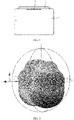
- FIG. 1 is a schematic diagram of a structure of a tablet computer according to the conventional technology.
- FIG. 2 is a radiation pattern of a Wi-Fi antenna of the tablet computer in FIG. 1.
- FIG. 1 is a schematic diagram of a structure of a tablet computer.
- a stylus is disposed on a side surface of a body 1' of the tablet computer. Being limited by an appearance or another reason, a position of a Wi-Fi antenna 3' is located near the stylus, and a straight closed slot antenna design is usually used.
- a 2.4 GHz Wi-Fi antenna is used as an example. As shown in FIG.
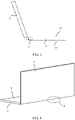
- FIG. 3 is a side view of a notebook computer according to the conventional technology.
- FIG. 4 is a schematic diagram of a three-dimensional structure of the notebook computer in FIG. 3 .
- FIG. 5 is a schematic diagram of an enlarged structure of an area B in FIG. 4 .
- FIG. 6 is a schematic diagram of an enlarged structure of a part of side surface of the notebook computer in FIG. 3 .
- FIG. 7 is a schematic diagram of a cross-sectional structure in a direction AA' in FIG. 6 .
- FIG. 8 is a radiation pattern of a Wi-Fi antenna of the notebook computer in FIG. 3 .
- the notebook computer includes a screen 4' and a body part 5'.
- the body part 5' includes an upper housing 51', a lower housing 52', and a side housing 53' close to a hinge.
- the screen 4' is omitted in FIG. 5
- the side housing 53' close to the hinge has a recessed area C
- a Wi-Fi antenna 6' is disposed in the area C.
- a specific structure of the Wi-Fi antenna 6' is omitted in FIG. 5 .
- the antenna 6' is usually disposed in the recessed area C.
- a conventional antenna 6' is designed in a form of an inverted-F antenna (Inverted-F Antenna, IFA).
- IFA Inverted-F Antenna
- a feed position D is located between the antenna 6' and the lower housing 52'.
- the lower housing 52' is grounded.
- a 2.4 GHz Wi-Fi antenna is used as an example.
- FIG. 8 because of impact on the antenna that is caused by the screen 4', a radiation intensity difference between upper and lower sides of the antenna is relatively large, and therefore a directivity factor of the antenna is relatively large and reaches at least 8 dBi.
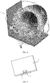
- FIG. 9 is a schematic diagram of a three-dimensional structure of a terminal according to an embodiment of this application.
- FIG. 10 is a top view of the terminal in FIG. 9 .
- An embodiment of this application provides a terminal, including a terminal body part 1 and an electronic accessory part 2.
- a Wi-Fi antenna apparatus is disposed on the terminal body part 1, the Wi-Fi antenna apparatus has a closed slot antenna 3, the closed slot antenna 3 includes a main straight slot 30 and a first slot 31 and a second slot 32 that are separately bent from two ends of the main straight slot 30 and extend to a same side of the main straight slot 30, both the first slot 31 and the second slot 32 are perpendicular to the main straight slot 30, and the electronic accessory part 2 is located on a side surface of the main straight slot 30.
- electric field directions are consistent on two sides of a slot of the closed slot antenna 3.
- an electric field direction at the main straight slot 30 is from top to bottom
- an electric field direction at the first slot 31 is from left to right
- an electric field direction at the second slot 32 is from right to left. Because the first slot 31 and the second slot 32 are opposite, electric fields at the first slot 31 and the second slot 32 offset against each other instead of being superposed, so that radiation enhancement of the antenna in a same direction is reduced.
- FIG. 11 is a radiation pattern of the Wi-Fi antenna of the terminal in FIG. 10 . It can be learned that the directivity factor of the Wi-Fi antenna of the terminal in FIG. 11 is less than that in FIG. 2 , is close to 3.5 dBi, and is less than a directivity factor of a straight slot antenna.
- the first slot and the second slot that are bent to the same side from two ends of the main straight slot are disposed, so that the electric fields at the first slot and the second slot offset against each other. Therefore, when the layout position of the Wi-Fi antenna is limited, radiation intensity of the antenna in a same direction can be reduced, in other words, the directivity factor of the antenna is reduced, so that transmit power of the antenna is improved.
- the terminal body part 1 is a flat-panel structure
- the terminal body part 1 includes two opposite main surfaces and a side surface connecting the two main surfaces
- an antenna slot of the closed slot antenna 3 is disposed on one of the two main surfaces
- the electronic accessory part 2 is detachably connected to a relative position of the side surface of the terminal body part 1.
- antenna directivity of the closed slot antenna 3 is adversely affected if the electronic accessory part 2 is disposed on the side surface of the terminal body part 1.
- adverse impact on antenna directivity that is caused by the electronic accessory part 2 is reduced, and the directivity factor of the antenna is reduced.
- FIG. 12 is a top view of another terminal according to an embodiment of this application.
- An antenna slot of a closed slot antenna 3 is shaped in "U" or non-closed square.
- the main straight slot 30, the first slot 31, and the second slot 32 form a "U"-shaped structure, to form the closed slot antenna 3.
- the antenna slot of the closed slot antenna 3 includes a third slot 33 and a fourth slot 34.
- the third slot 33 is bent and extends to the right from a lower end of the first slot 31, and the fourth slot 34 is bent and extends to the left from a lower end of the second slot 32.
- the main straight slot 30, the first slot 31, the second slot 32, the third slot 33, and the fourth slot 34 form a structure of non-closed square, to form the closed slot antenna 3.
- a directivity factor of the Wi-Fi antenna of the terminal in FIG. 13 is less than that in FIG. 2 , is close to 3.5 dBi, and is less than a directivity factor of a straight slot antenna.
- the terminal body part 1 is a tablet computer
- the electronic accessory part 2 is a stylus.
- the stylus may be adsorbed on a side surface of the tablet computer.
- the antenna slot of the closed slot antenna 3 is located near a rear housing of the tablet computer, and is adjacent to a side on which the stylus is adsorbed.
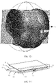
- FIG. 14 is a schematic diagram of a three-dimensional structure of another terminal according to an embodiment of this application.
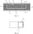
- FIG. 15 is a schematic diagram of an enlarged structure at a closed slot antenna in FIG. 14 .
- FIG. 16 is a schematic diagram of a cross-sectional structure in a direction EE' in FIG. 15 .
- the terminal is a notebook computer, and a terminal body part 1 is a computer body part, and the terminal body part 1 includes an upper housing 11 and a lower housing 12 that are opposite and four side housings 13 connecting the upper housing 11 and the lower housing 12.
- An electronic accessory part 2 is a display, the terminal body part 1 has a hinge area 4 on a side edge of one side housing 13, and the electronic accessory part 2 is connected to the terminal body part 1 in the hinge area 4 by a hinge.
- a closed slot antenna 3 is located on the side housing 13 corresponding to the hinge area 4.
- an antenna slot of the closed slot antenna 3 may be a slot of the side housing 13, or an antenna slot of the closed slot antenna 3 may be a slot of a conductive plate disposed on the side housing 13.
- the closed slot antenna 3 also includes a main straight slot 30 and a first slot 31 and a second slot 32 that are separately bent from two ends of the main straight slot 30 and extend to a same side of the main straight slot 30, both the first slot 31 and the second slot 32 are perpendicular to the main straight slot 30, and the electronic accessory part 2 is located on a side surface of the main straight slot 30.
- a position of the closed slot antenna 3 is limited to the side housing 13 corresponding to the hinge area 4. Therefore, the display causes adverse impact on antenna directivity of the closed slot antenna 3.
- electric fields at the first slot 31 and the second slot 32 offset against each other radiation enhancement of the antenna in a same direction is reduced, in other words, a directivity factor of the antenna is reduced, so that transmit power of the antenna is improved.
- a display surface of the electronic accessory part 2 is facing to the upper housing 11 of the terminal body part 1.
- the upper housing 11 of the terminal body part 1 is a ground electrically connected to the closed slot antenna 3.
- the upper housing 11 of the terminal body part 1 when the upper housing 11 of the terminal body part 1 is a ground electrically connected to the closed slot antenna 3, the upper housing 11 of the terminal body part 1 is grounded.
- the upper housing 11 is located between the display and the closed slot antenna 3. Radiation impact on the closed slot antenna 3 that is caused by the display is to radiate more radiation beams upward, and the ground reflects radiation of the antenna, in other words, the upper housing 11 enables a radiation beam of the antenna to be reflected downward. Therefore, disposing the upper housing 11 as the ground can reduce adverse impact on a radiation direction of the closed slot antenna 3 that is caused by the display, to further reduce the directivity factor of the antenna, so that transmit power of the antenna is improved.
- the antenna slot of the closed slot antenna 3 is shaped in non-closed square.
- a height of the side housing 13 of the notebook computer is usually relatively small.
- the antenna slot of the closed slot antenna 3 is set to a shape of non-closed square.
- the closed slot antenna 3 further includes a third slot 33 and a fourth slot 34, the third slot 33 is bent and extends to the right from an upper end of the first slot 31, the fourth slot 34 is bent and extends to the left from an upper end of the second slot 32, and the main straight slot 30, the first slot 31, the second slot 32, the third slot 33, and the fourth slot 34 form a structure of non-closed square, to form the closed slot antenna 3.
- an end of the antenna slot of the closed slot antenna 3 is located on a side that is of the antenna slot and that is close to the upper housing 11 of the terminal body part 1.
- both an end of the third slot 33 and an end of the fourth slot 34 are located on a side that is of the main straight slot 30 and that is close to the upper housing 11.
- the end of the third slot 33 is connected to the upper housing 11, and a feed point 35 is disposed herein, to separately implement feeding by using the feed point 35 and the upper housing 11.
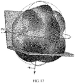
- FIG. 17 is a radiation pattern of a Wi-Fi antenna of the terminal in FIG. 14 . It can be learned that a directivity factor of the Wi-Fi antenna of the terminal in FIG. 17 is less than that in FIG. 8 , is close to 5.2 dBi, and is less than a directivity factor of an IFA antenna.
- "at least one” means one or more, and "a plurality of' means two or more.
- the term “and/or” describes an association relationship for describing associated objects and indicates that three relationships may exist.
- a and/or B may indicate the following three cases: Only A exists, both A and B exist, and only B exists.
- a and B may be in a singular form or a plural form.
- the character "/” generally indicates an "or” relationship between the associated objects.
- At least one of the following items and similar expressions refer to any combination of the items, including a single item or any combination of plural items.
- At least one of a, b, and c may indicate a, b, c, a and b, a and c, b and c, or a, b, and c, where a, b, and c may be singular or plural.
Landscapes
- Engineering & Computer Science (AREA)
- General Engineering & Computer Science (AREA)
- Theoretical Computer Science (AREA)
- Computer Hardware Design (AREA)
- Computer Networks & Wireless Communication (AREA)
- Human Computer Interaction (AREA)
- Physics & Mathematics (AREA)
- General Physics & Mathematics (AREA)
- Support Of Aerials (AREA)
- Details Of Aerials (AREA)
- Telephone Set Structure (AREA)
Applications Claiming Priority (2)
| Application Number | Priority Date | Filing Date | Title |
|---|---|---|---|
| CN202010117703.8A CN113381163B (zh) | 2020-02-25 | 2020-02-25 | 终端 |
| PCT/CN2020/136405 WO2021169500A1 (zh) | 2020-02-25 | 2020-12-15 | 终端 |
Publications (2)
| Publication Number | Publication Date |
|---|---|
| EP4096018A1 true EP4096018A1 (de) | 2022-11-30 |
| EP4096018A4 EP4096018A4 (de) | 2023-07-26 |
Family
ID=77489848
Family Applications (1)
| Application Number | Title | Priority Date | Filing Date |
|---|---|---|---|
| EP20921030.1A Pending EP4096018A4 (de) | 2020-02-25 | 2020-12-15 | Endgerät |
Country Status (5)
| Country | Link |
|---|---|
| US (1) | US12327910B2 (de) |
| EP (1) | EP4096018A4 (de) |
| CN (2) | CN113381163B (de) |
| BR (1) | BR112022017019A2 (de) |
| WO (1) | WO2021169500A1 (de) |
Families Citing this family (2)
| Publication number | Priority date | Publication date | Assignee | Title |
|---|---|---|---|---|
| US12212059B2 (en) * | 2021-04-21 | 2025-01-28 | Dell Products Lp | System and method for operating a partitioned antenna at a vent formed in a bottom metal chassis |
| US20230350467A1 (en) * | 2022-04-29 | 2023-11-02 | Dell Products, Lp | Horseshoe hinge frame antenna for an information handling system |
Family Cites Families (20)
| Publication number | Priority date | Publication date | Assignee | Title |
|---|---|---|---|---|
| TW537454U (en) * | 2002-05-14 | 2003-06-11 | High Tech Comp Corp | Stylus-accommodating structure for wireless communication apparatus |
| US20050146475A1 (en) | 2003-12-31 | 2005-07-07 | Bettner Allen W. | Slot antenna configuration |
| CN101471486A (zh) * | 2007-12-24 | 2009-07-01 | 联想(上海)有限公司 | 一种天线 |
| EP2503637B1 (de) * | 2011-03-23 | 2017-01-18 | BlackBerry Limited | Drahtlose mobile Kommunikationsvorrichtung mit Schlitzantenne und zugehörige Verfahren |
| KR101787384B1 (ko) * | 2011-06-10 | 2017-10-20 | 삼성전자주식회사 | 휴대용 단말기의 안테나 장치 |
| US9268379B2 (en) * | 2012-07-27 | 2016-02-23 | Hewlett-Packard Development Company, L.P. | Stylus and holder device associated therewith |
| TWI521792B (zh) * | 2012-09-07 | 2016-02-11 | 啟碁科技股份有限公司 | 雙頻天線 |
| TWI528639B (zh) * | 2012-10-09 | 2016-04-01 | 啟碁科技股份有限公司 | 天線裝置及無線通訊裝置 |
| KR101944340B1 (ko) * | 2012-12-28 | 2019-01-31 | 엘지디스플레이 주식회사 | 슬롯 안테나와 이를 이용한 정보 단말 장치 |
| US9596914B2 (en) * | 2013-04-19 | 2017-03-21 | Joseph A. Zaloom | Tablet transformer |
| TWI599099B (zh) * | 2015-07-03 | 2017-09-11 | 宏碁股份有限公司 | 行動裝置 |
| JP6586341B2 (ja) * | 2015-10-01 | 2019-10-02 | Dynabook株式会社 | 電子機器、ペン、及びペンの保持方法 |
| TWI597962B (zh) * | 2016-04-22 | 2017-09-01 | 廣達電腦股份有限公司 | 行動裝置 |
| CN106058461B (zh) * | 2016-07-22 | 2019-03-08 | 常熟市泓博通讯技术股份有限公司 | 具有天线的电子装置 |
| CN106502321B (zh) * | 2016-09-29 | 2019-08-30 | 苏州佳世达电通有限公司 | 一种电子装置 |
| TWI627794B (zh) * | 2017-01-18 | 2018-06-21 | 和碩聯合科技股份有限公司 | 電子裝置及其天線單元 |
| US11329364B2 (en) | 2017-03-15 | 2022-05-10 | Sony Mobile Communications Inc. | Communication apparatus |
| TWI635653B (zh) * | 2017-04-18 | 2018-09-11 | 華碩電腦股份有限公司 | 天線元件 |
| GB201813970D0 (en) | 2018-08-28 | 2018-10-10 | Smart Antenna Tech Limited | Compact LTE Antenna with WiFi support |
| CN112751155B (zh) * | 2019-10-31 | 2022-04-05 | 华为技术有限公司 | 电子设备 |
-
2020
- 2020-02-25 CN CN202010117703.8A patent/CN113381163B/zh active Active
- 2020-02-25 CN CN202311470434.3A patent/CN117691339A/zh not_active Withdrawn
- 2020-12-15 EP EP20921030.1A patent/EP4096018A4/de active Pending
- 2020-12-15 WO PCT/CN2020/136405 patent/WO2021169500A1/zh not_active Ceased
- 2020-12-15 US US17/802,346 patent/US12327910B2/en active Active
- 2020-12-15 BR BR112022017019A patent/BR112022017019A2/pt unknown
Also Published As
| Publication number | Publication date |
|---|---|
| CN117691339A (zh) | 2024-03-12 |
| WO2021169500A1 (zh) | 2021-09-02 |
| US20230155275A1 (en) | 2023-05-18 |
| US12327910B2 (en) | 2025-06-10 |
| EP4096018A4 (de) | 2023-07-26 |
| CN113381163A (zh) | 2021-09-10 |
| CN113381163B (zh) | 2023-11-10 |
| BR112022017019A2 (pt) | 2022-10-11 |
Similar Documents
| Publication | Publication Date | Title |
|---|---|---|
| US7589680B2 (en) | Antenna unit with a parasitic coupler | |
| KR102612938B1 (ko) | 안테나 모듈을 포함하는 전자 장치 | |
| US10069196B1 (en) | Mobile device | |
| US20180331415A1 (en) | Electronic device and antenna structure thereof | |
| CN208142342U (zh) | 头戴式显示器装置 | |
| EP3852194B1 (de) | Antenne für endgerät | |
| EP4096018A1 (de) | Endgerät | |
| KR102890812B1 (ko) | 안테나 및 그것을 포함하는 전자 장치 | |
| EP2677596A1 (de) | Kommunikationsvorrichtung und Antennensystem darin | |
| US10431881B2 (en) | Electronic apparatus and dual band printed antenna of the same | |
| US12119543B2 (en) | Antenna and electronic device comprising the same | |
| US11460891B2 (en) | Electronic device | |
| EP3091608A1 (de) | Antennensystem und antennenmodul mit einem parasitären element für strahlungsmusterverbesserungen | |
| EP4372909A1 (de) | Elektronische vorrichtung mit antenne | |
| CN117996413A (zh) | 天线模块及电子装置 | |
| EP3827474B1 (de) | Antenne und drahtlose kommunikationsvorrichtung | |
| TWI782647B (zh) | 電子裝置 | |
| CN104681993B (zh) | 天线装置 | |
| CN110474150B (zh) | 无净空区的天线 | |
| US20230178883A1 (en) | Keyboard module | |
| KR20240043629A (ko) | 안테나를 포함하는 전자 장치 | |
| US20190296438A1 (en) | Mobile device | |
| EP4290690A1 (de) | Antenne und elektronische vorrichtung damit | |
| CN204333254U (zh) | 电子装置 | |
| EP4191792A1 (de) | Antennenvorrichtung |
Legal Events
| Date | Code | Title | Description |
|---|---|---|---|
| STAA | Information on the status of an ep patent application or granted ep patent |
Free format text: STATUS: THE INTERNATIONAL PUBLICATION HAS BEEN MADE |
|
| PUAI | Public reference made under article 153(3) epc to a published international application that has entered the european phase |
Free format text: ORIGINAL CODE: 0009012 |
|
| STAA | Information on the status of an ep patent application or granted ep patent |
Free format text: STATUS: REQUEST FOR EXAMINATION WAS MADE |
|
| 17P | Request for examination filed |
Effective date: 20220822 |
|
| AK | Designated contracting states |
Kind code of ref document: A1 Designated state(s): AL AT BE BG CH CY CZ DE DK EE ES FI FR GB GR HR HU IE IS IT LI LT LU LV MC MK MT NL NO PL PT RO RS SE SI SK SM TR |
|
| DAV | Request for validation of the european patent (deleted) | ||
| DAX | Request for extension of the european patent (deleted) | ||
| A4 | Supplementary search report drawn up and despatched |
Effective date: 20230623 |
|
| RIC1 | Information provided on ipc code assigned before grant |
Ipc: H01Q 9/42 20060101ALN20230619BHEP Ipc: H01Q 13/16 20060101ALI20230619BHEP Ipc: H01Q 13/18 20060101ALI20230619BHEP Ipc: H01Q 1/22 20060101AFI20230619BHEP |