EP4096040B1 - Alimentation électrique de véhicule - Google Patents
Alimentation électrique de véhicule Download PDFInfo
- Publication number
- EP4096040B1 EP4096040B1 EP20915202.4A EP20915202A EP4096040B1 EP 4096040 B1 EP4096040 B1 EP 4096040B1 EP 20915202 A EP20915202 A EP 20915202A EP 4096040 B1 EP4096040 B1 EP 4096040B1
- Authority
- EP
- European Patent Office
- Prior art keywords
- power supply
- voltage
- node
- supply device
- power storage
- Prior art date
- Legal status (The legal status is an assumption and is not a legal conclusion. Google has not performed a legal analysis and makes no representation as to the accuracy of the status listed.)
- Active
Links
Images




Classifications
-
- H—ELECTRICITY
- H02—GENERATION; CONVERSION OR DISTRIBUTION OF ELECTRIC POWER
- H02J—ELECTRIC POWER NETWORKS; CIRCUIT ARRANGEMENTS OR SYSTEMS FOR SUPPLYING OR DISTRIBUTING ELECTRIC POWER; SYSTEMS FOR STORING ELECTRIC ENERGY
- H02J7/00—Circuit arrangements for charging or discharging batteries or for supplying loads from batteries
- H02J7/50—Circuit arrangements for charging or discharging batteries or for supplying loads from batteries acting upon multiple batteries simultaneously or sequentially
- H02J7/52—Circuit arrangements for charging or discharging batteries or for supplying loads from batteries acting upon multiple batteries simultaneously or sequentially for charge balancing, e.g. equalisation of charge between batteries
- H02J7/56—Active balancing, e.g. using capacitor-based, inductor-based or DC-DC converters
-
- B—PERFORMING OPERATIONS; TRANSPORTING
- B60—VEHICLES IN GENERAL
- B60L—PROPULSION OF ELECTRICALLY-PROPELLED VEHICLES; SUPPLYING ELECTRIC POWER FOR AUXILIARY EQUIPMENT OF ELECTRICALLY-PROPELLED VEHICLES; ELECTRODYNAMIC BRAKE SYSTEMS FOR VEHICLES IN GENERAL; MAGNETIC SUSPENSION OR LEVITATION FOR VEHICLES; MONITORING OPERATING VARIABLES OF ELECTRICALLY-PROPELLED VEHICLES; ELECTRIC SAFETY DEVICES FOR ELECTRICALLY-PROPELLED VEHICLES
- B60L3/00—Electric devices on electrically-propelled vehicles for safety purposes; Monitoring operating variables, e.g. speed, deceleration or energy consumption
- B60L3/0023—Detecting, eliminating, remedying or compensating for drive train abnormalities, e.g. failures within the drive train
- B60L3/0046—Detecting, eliminating, remedying or compensating for drive train abnormalities, e.g. failures within the drive train relating to electric energy storage systems, e.g. batteries or capacitors
-
- B—PERFORMING OPERATIONS; TRANSPORTING
- B60—VEHICLES IN GENERAL
- B60L—PROPULSION OF ELECTRICALLY-PROPELLED VEHICLES; SUPPLYING ELECTRIC POWER FOR AUXILIARY EQUIPMENT OF ELECTRICALLY-PROPELLED VEHICLES; ELECTRODYNAMIC BRAKE SYSTEMS FOR VEHICLES IN GENERAL; MAGNETIC SUSPENSION OR LEVITATION FOR VEHICLES; MONITORING OPERATING VARIABLES OF ELECTRICALLY-PROPELLED VEHICLES; ELECTRIC SAFETY DEVICES FOR ELECTRICALLY-PROPELLED VEHICLES
- B60L3/00—Electric devices on electrically-propelled vehicles for safety purposes; Monitoring operating variables, e.g. speed, deceleration or energy consumption
- B60L3/0023—Detecting, eliminating, remedying or compensating for drive train abnormalities, e.g. failures within the drive train
- B60L3/0069—Detecting, eliminating, remedying or compensating for drive train abnormalities, e.g. failures within the drive train relating to the isolation, e.g. ground fault or leak current
-
- B—PERFORMING OPERATIONS; TRANSPORTING
- B60—VEHICLES IN GENERAL
- B60L—PROPULSION OF ELECTRICALLY-PROPELLED VEHICLES; SUPPLYING ELECTRIC POWER FOR AUXILIARY EQUIPMENT OF ELECTRICALLY-PROPELLED VEHICLES; ELECTRODYNAMIC BRAKE SYSTEMS FOR VEHICLES IN GENERAL; MAGNETIC SUSPENSION OR LEVITATION FOR VEHICLES; MONITORING OPERATING VARIABLES OF ELECTRICALLY-PROPELLED VEHICLES; ELECTRIC SAFETY DEVICES FOR ELECTRICALLY-PROPELLED VEHICLES
- B60L58/00—Methods or circuit arrangements for monitoring or controlling batteries or fuel cells, specially adapted for electric vehicles
- B60L58/10—Methods or circuit arrangements for monitoring or controlling batteries or fuel cells, specially adapted for electric vehicles for monitoring or controlling batteries
- B60L58/12—Methods or circuit arrangements for monitoring or controlling batteries or fuel cells, specially adapted for electric vehicles for monitoring or controlling batteries responding to state of charge [SoC]
-
- B—PERFORMING OPERATIONS; TRANSPORTING
- B60—VEHICLES IN GENERAL
- B60L—PROPULSION OF ELECTRICALLY-PROPELLED VEHICLES; SUPPLYING ELECTRIC POWER FOR AUXILIARY EQUIPMENT OF ELECTRICALLY-PROPELLED VEHICLES; ELECTRODYNAMIC BRAKE SYSTEMS FOR VEHICLES IN GENERAL; MAGNETIC SUSPENSION OR LEVITATION FOR VEHICLES; MONITORING OPERATING VARIABLES OF ELECTRICALLY-PROPELLED VEHICLES; ELECTRIC SAFETY DEVICES FOR ELECTRICALLY-PROPELLED VEHICLES
- B60L58/00—Methods or circuit arrangements for monitoring or controlling batteries or fuel cells, specially adapted for electric vehicles
- B60L58/10—Methods or circuit arrangements for monitoring or controlling batteries or fuel cells, specially adapted for electric vehicles for monitoring or controlling batteries
- B60L58/18—Methods or circuit arrangements for monitoring or controlling batteries or fuel cells, specially adapted for electric vehicles for monitoring or controlling batteries of two or more battery modules
- B60L58/20—Methods or circuit arrangements for monitoring or controlling batteries or fuel cells, specially adapted for electric vehicles for monitoring or controlling batteries of two or more battery modules having different nominal voltages
-
- B—PERFORMING OPERATIONS; TRANSPORTING
- B60—VEHICLES IN GENERAL
- B60L—PROPULSION OF ELECTRICALLY-PROPELLED VEHICLES; SUPPLYING ELECTRIC POWER FOR AUXILIARY EQUIPMENT OF ELECTRICALLY-PROPELLED VEHICLES; ELECTRODYNAMIC BRAKE SYSTEMS FOR VEHICLES IN GENERAL; MAGNETIC SUSPENSION OR LEVITATION FOR VEHICLES; MONITORING OPERATING VARIABLES OF ELECTRICALLY-PROPELLED VEHICLES; ELECTRIC SAFETY DEVICES FOR ELECTRICALLY-PROPELLED VEHICLES
- B60L58/00—Methods or circuit arrangements for monitoring or controlling batteries or fuel cells, specially adapted for electric vehicles
- B60L58/10—Methods or circuit arrangements for monitoring or controlling batteries or fuel cells, specially adapted for electric vehicles for monitoring or controlling batteries
- B60L58/18—Methods or circuit arrangements for monitoring or controlling batteries or fuel cells, specially adapted for electric vehicles for monitoring or controlling batteries of two or more battery modules
- B60L58/21—Methods or circuit arrangements for monitoring or controlling batteries or fuel cells, specially adapted for electric vehicles for monitoring or controlling batteries of two or more battery modules having the same nominal voltage
-
- H—ELECTRICITY
- H02—GENERATION; CONVERSION OR DISTRIBUTION OF ELECTRIC POWER
- H02H—EMERGENCY PROTECTIVE CIRCUIT ARRANGEMENTS
- H02H3/00—Emergency protective circuit arrangements for automatic disconnection directly responsive to an undesired change from normal electric working condition with or without subsequent reconnection ; integrated protection
- H02H3/16—Emergency protective circuit arrangements for automatic disconnection directly responsive to an undesired change from normal electric working condition with or without subsequent reconnection ; integrated protection responsive to fault current to earth, frame or mass
-
- H—ELECTRICITY
- H02—GENERATION; CONVERSION OR DISTRIBUTION OF ELECTRIC POWER
- H02H—EMERGENCY PROTECTIVE CIRCUIT ARRANGEMENTS
- H02H5/00—Emergency protective circuit arrangements for automatic disconnection directly responsive to an undesired change from normal non-electric working conditions with or without subsequent reconnection
- H02H5/12—Emergency protective circuit arrangements for automatic disconnection directly responsive to an undesired change from normal non-electric working conditions with or without subsequent reconnection responsive to undesired approach to, or touching of, live parts by living beings
-
- H—ELECTRICITY
- H02—GENERATION; CONVERSION OR DISTRIBUTION OF ELECTRIC POWER
- H02J—ELECTRIC POWER NETWORKS; CIRCUIT ARRANGEMENTS OR SYSTEMS FOR SUPPLYING OR DISTRIBUTING ELECTRIC POWER; SYSTEMS FOR STORING ELECTRIC ENERGY
- H02J7/00—Circuit arrangements for charging or discharging batteries or for supplying loads from batteries
- H02J7/50—Circuit arrangements for charging or discharging batteries or for supplying loads from batteries acting upon multiple batteries simultaneously or sequentially
- H02J7/575—Parallel/serial switching of connection of batteries to charge or load circuit
-
- B—PERFORMING OPERATIONS; TRANSPORTING
- B60—VEHICLES IN GENERAL
- B60L—PROPULSION OF ELECTRICALLY-PROPELLED VEHICLES; SUPPLYING ELECTRIC POWER FOR AUXILIARY EQUIPMENT OF ELECTRICALLY-PROPELLED VEHICLES; ELECTRODYNAMIC BRAKE SYSTEMS FOR VEHICLES IN GENERAL; MAGNETIC SUSPENSION OR LEVITATION FOR VEHICLES; MONITORING OPERATING VARIABLES OF ELECTRICALLY-PROPELLED VEHICLES; ELECTRIC SAFETY DEVICES FOR ELECTRICALLY-PROPELLED VEHICLES
- B60L2210/00—Converter types
- B60L2210/10—DC to DC converters
-
- B—PERFORMING OPERATIONS; TRANSPORTING
- B60—VEHICLES IN GENERAL
- B60L—PROPULSION OF ELECTRICALLY-PROPELLED VEHICLES; SUPPLYING ELECTRIC POWER FOR AUXILIARY EQUIPMENT OF ELECTRICALLY-PROPELLED VEHICLES; ELECTRODYNAMIC BRAKE SYSTEMS FOR VEHICLES IN GENERAL; MAGNETIC SUSPENSION OR LEVITATION FOR VEHICLES; MONITORING OPERATING VARIABLES OF ELECTRICALLY-PROPELLED VEHICLES; ELECTRIC SAFETY DEVICES FOR ELECTRICALLY-PROPELLED VEHICLES
- B60L2210/00—Converter types
- B60L2210/10—DC to DC converters
- B60L2210/12—Buck converters
Definitions
- the present invention relates to a power supply device mounted on a vehicle.
- the power supply device includes a high-voltage power storage means particularly used for vehicle traveling and the like, and a low-voltage power supply for supplying an electric load other than that for a vehicle traveling.
- the power supply device is configured to obtain the low voltage power supply from the high-voltage power storage means via a step-down means.
- a vehicle power supply device As the power supply device, a vehicle power supply device according to the proposal of the present applicant is known (Patent Publication (1)).
- the high voltage power supply is formed by connecting power storage elements in series.
- the vehicle power supply device performs power conversion from a high voltage to a low voltage by selectively connecting a predetermined power storage element group to a low voltage electric load.
- the vehicle power supply device switches the power storage element group at high speed to make the switching loss of the switching means almost zero.
- Patent Publication (1) Japanese Laid-Open Patent Publication No. 2018-26973
- the electric power storage means for driving the vehicle from a low voltage of about 48 V to a system using a high voltage of about 600 V.
- a vehicle using a voltage exceeding 60 V is provided with a configuration for preventing an electric shock accident. This prevents an electric shock accident when the human body touches the electric circuit portion connected to the power storage means of the vehicle.
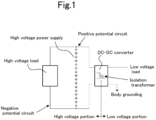
- a DC-DC converter provided with an isolation transformer is arranged between the high voltage part and the low voltage part as shown in FIG. 1 .
- the high voltage circuit floats both the negative potential circuit and the positive potential circuit while avoiding direct connection with the vehicle body.
- the low potential side of the load means 50 which is a low voltage circuit
- the vehicle body is a body ground of a 12V power supply.
- any one or more of the switch means (30 to 35) is closed, any of the connection points of the power storage means (20a to 20L) connected in series on the high voltage side is directly connected to the vehicle body. Therefore, if the human body touches the high voltage circuit, an electric shock will occur.
- the total series voltage of the power storage means (20a to 20L) is 480V.
- a high voltage of 480 V is applied to the human body. It is possible that an electric shock accident may occur.
- Other leakage detection methods in the same context could be found in patent document US2013/099795 .
- the present invention has been made in view of the above problems. This can be applied to a case where a vehicle power supply device mounted on a vehicle and obtaining a low voltage power supply from a high voltage power supply via a step-down means is configured as a system having a voltage exceeding 60 V on the high voltage power supply side. 60V is the voltage of the electric shock limit of the human body. Even in this case, it is possible to prevent an electric shock accident without using an insulating means such as a transformer. Further, the present invention provides a power supply device for a vehicle that easily obtains a power conversion efficiency of about 100% in a power conversion function to the low voltage side.
- the present invention described in Claim 1 is a power supply device for vehicle, comprising: an electric load that operates at a predetermined low voltage; a high-voltage power supply that obtains a high-voltage DC power supply by connecting in series a plurality of power storage elements constituting each node that supplies said predetermined low voltage; a high-voltage load device connected to the high-voltage power supply via a wire harness; a plurality of switch means provided corresponding to each node that supplies the predetermined low voltage to the electric load; a control means, wherein the control means supplies a voltage by turning on the switch means for supplying a voltage from at least one node and turning off the switch means for supplying a voltage from another node, after setting a dead time period to turn off all switch means once, by sequentially repeating the control of turning on the switch means of the node that supplies the voltage next and turning off the switch means that supplies the voltage from the other node, the voltage is supplied from all the storage elements; a cutoff means for cutting off an electric circuit between the high-
- the present invention described in Claim 2 is a power supply device for a vehicle, wherein in said high voltage power supply, a plurality of power storage elements constituting the node of which n (n: natural number) pieces make up the predetermined low voltage are connected in series (n ⁇ N (N: natural number)), and DC power source having a high voltage N times the predetermined low voltage can be obtained.
- the present invention described in Claim 3 is a power supply device for a vehicle, wherein said control means controls the switch means so as to periodically change a plurality of selected nodes.
- the present invention described in Claim 4 is a power supply device for a vehicle, wherein said control means determines a node to be selected so that the charge / discharge states of the plurality of power storage elements become substantially uniform.
- the present invention described in Claim 5 is a power supply device for a vehicle, wherein said control means determines a selective holding time of each node so that the charge / discharge states of the plurality of power storage elements become substantially uniform.
- the present invention described in Claim 6 is a power supply device for a vehicle, wherein a time connecting any of node to said electric load by said switch means is set so as to a time during which the leakage current flowing from the high voltage power supply to the human body to be less than a time during which causes an electric shock accident in the human body.
- the present invention described in Claim 7 is a power supply device for a vehicle, wherein said time connecting any of node to said electric load by said switch means is set so as to a time during which inversely proportional to the voltage value of the high voltage power supply, or a time during which inversely proportional to the current value detected by the leakage detecting means.
- the present invention described in Claim 8 is a power supply device for a vehicle, wherein said control means fixes the cutoff means to an off state when the leakage detection value of said leakage detection means is equal to or higher than a predetermined current value.
- the present invention described in Claim 9 is a power supply device for a vehicle, wherein said control means holds a state in which the cutoff means are off for a predetermined time when the leakage detection value of the leakage detection means is equal to or higher than a predetermined current value, and after that, again repeats the operation in which the cutoff means are on.
- the present invention described in Claim 10 is a power supply device for a vehicle, wherein said control means controls said switching means so as to a product of a period in which each node and the electric load are connected and the leakage detection value of the leakage detection means is 0.003 amperes ⁇ 1 second or less.
- the present invention described in Claim 11 is a power supply device for a vehicle, wherein said control means sets a cycle for switching a node selected by said switching means to a predetermined value or less so that a magnitude of a charge / discharge depth in each node of the power storage element is equal to or less than a predetermined value.
- the present invention described in Claim 12 is a power supply device for a vehicle, wherein a capacitor is connected in parallel with the electric load.
- the present invention described in Claim 13 is a power supply device for a vehicle, wherein said dead time period or a capacitance value of the capacitor is set so that a voltage drop width applied to the electric load during the dead time period is not more than a predetermined value.
- the present invention described in Claim 14 is a power supply device for a vehicle, wherein the capacitor is arranged in parallel with each node of said power storage element.
- the present invention described in Claim 15 is a power supply device for a vehicle, wherein from each node of the high-voltage power source that obtains a high-voltage DC power supply by connecting in series a plurality of power storage elements, AC power is supplied to the electric load by alternately reversing the polarity with a potential side and a lower side at predetermined periods when the electric load is connected by the switching means.
- four power storage elements connected in series may be selected in a group manner and connected to an electric load.
- Step-down can be realized by a simple switching means that selectively connects to an electric load from each node (group node) of the power storage element connected in series.
- the configuration of the switching means can be simplified. Since the known switching loss and the loss generated from the inductor can be significantly reduced, the power loss for step-down can be reduced and the heat dissipation structure can be simplified. As a result, the weight and cost of the power supply device including the device for such step-down can be reduced.
- a part of the nodes of the power storage element connected in series of the high voltage power supply is connected to the low voltage circuit, that is, the metal part of the vehicle body via the switching means.
- control means detects the current flowing from the high voltage power supply through the human body as the measured current value of the leakage detection means during the dead time period when all the switching means are turned off.
- the cutoff means for disconnecting the electric circuit connected to the high voltage load device from the vehicle power supply device via the wire harness connected to the outside is held in the off state, an electric shock accident can be prevented.
- the vehicle power supply device described in Claim 2 in the high voltage power supply, a plurality of power storage elements constituting a node having a predetermined low voltage with n (n: natural number) are connected in series (n ⁇ N (N: natural number)). A DC power supply having a high voltage N times a predetermined low voltage is obtained. Therefore, it is possible to efficiently supply a high voltage and a predetermined low voltage by using all the power storage elements.
- the control means periodically changes the node selected by the switching means from the plurality of power storage elements.
- the control means periodically changes the node selected by the switching means from the plurality of power storage elements.
- the power storage elements connected in series it is possible to prevent a problem that only a part of the power storage elements is discharged and the other power storage elements are overcharged.
- control means determines the node to be selected so that the charge / discharge states of the plurality of power storage elements are substantially uniform. It also has a known cell balance function required when charging and discharging a plurality of power storage elements in series.
- the control means determines the selective holding time of each node so that the charge / discharge states of the plurality of power storage elements become substantially uniform.
- the selective holding time of each node is determined so that the charge / discharge state of the plurality of power storage elements becomes substantially uniform and the discharge time is long for the node selected from the power storage elements having a large charge amount.
- the selective holding time of each node is determined so that the discharge time is short for the node selected from the power storage elements having a small charge amount. It also has a known cell balance function required when charging and discharging a plurality of power storage elements in series.
- the earth-leakage detection sensitivity of 30 mA ⁇ 0.1 sec is set.
- the control means sets the period for connecting each node to the low-voltage electric load by the switching means to be less than the time during which an electric shock accident occurs in the human body. This period is the duration of the leakage current flowing from the high voltage power supply to the human body. Even when a person touches a circuit part of a high voltage power supply, it is possible to eliminate the damage to the human body.
- the control means is set so that the period for connecting each node and the electric load by the switching means is a duration inversely proportional to the voltage value of the high voltage power supply.
- the duration is set to be inversely proportional to the leakage current value to the human body.
- the control means fixes the cutoff means to the OFF state when the leakage detection value of the leakage detection means is equal to or higher than a predetermined current value.
- the high voltage power supply continues to float from the vehicle body, so that safety is further improved.
- the control means holds a state in which the cutoff means are OFF for a predetermined time such as 0.5 seconds when the leakage detection value of the leakage detection means is equal to or higher than a predetermined current value. After that, the cutoff means repeats the operation of turning ON. Ensure safety by giving a sufficient pause time to the electric shock current to the human body. Even if a temporary leakage current occurs due to a failure of each part of the power supply device of the vehicle body, the power supply from the high voltage power supply to the high voltage load device is resumed, so that the vehicle function can be maintained.
- a predetermined time such as 0.5 seconds when the leakage detection value of the leakage detection means is equal to or higher than a predetermined current value.
- the control means controls the switching means so that the product of the period for connecting each node and the electric load and the leakage detection value of the leakage detection means is 0.003 amperes ⁇ 1 second or less. It is possible to secure the same level of safety as the standard 0.03 amps ⁇ 0.1 seconds or less of the earth-leakage circuit breaker used in general commercial power supplies.
- control means sets a cycle for switching the node selected by the switching means so that the magnitude of the charge / discharge depth at each node of the power storage element is equal to or less than a predetermined value. It is possible to minimize the decrease in the life of each power storage element due to the charging / discharging depth of each power storage element being too large.
- the control means powers the switching means from the capacitor during a so-called dead time period that disconnects the connection between all the nodes and the electrical load. As a result, it is possible to prevent the voltage supplied to the electric load from dropping. The voltage supplied to the electric load can be kept stable.
- a capacitor with a small internal impedance is placed in parallel with the series node of the power storage element. Immediately after the switching means switches the connection to any node, the capacitor can be charged with a sufficiently small power supply impedance, that is, a large current. It is possible to suppress a decrease in the voltage supplied to the electric load.
- the vehicle power supply device described in Claim 15 power is supplied from each node of a high voltage power supply that obtains a high-voltage DC power supply by connecting a plurality of power storage elements in series.
- the polarities of the high-potential side and the low-potential side when connected to the electric load by the switching means are alternately reversed at predetermined intervals.
- AC power is supplied to the electric load.
- AC power can be supplied from the vehicle for the use of household appliances that require commercial power.
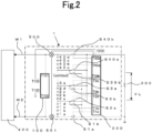
- FIG. 2 is a basic embodiment of the present invention.
- a vehicle power supply device 1 includes power storage elements (1a to 40d) constituting a secondary battery charged by a power generation means (not shown) mechanically connected to a drive mechanism mounted on the vehicle and traveling by an engine and a motor.
- the vehicle power supply device 1 includes switching means (Sla to S40b), control means 200, leakage detection means 100, and cutoff means 500, 501.
- the vehicle power supply device is connected to electric load 300 which is operated by 12V, and one end on the negative potential side is electrically connected to the vehicle body.
- the vehicle power supply device 1 is connected to the high voltage load device 400 via the wire harnesses W1 and W2, and supplies the electric power of the high voltage power storage elements 1a to 40d to the high voltage load device 400.
- the power storage elements (3b to 39d), the switching means (S3b to S39a) connected to the power storage elements, and the parts where the switching means and the control means 200 are connected are omitted.
- the power generation means is driven by an engine (not shown) in order to supply the electric power required for the vehicle electrical components.
- the power generation means is configured to regenerate the kinetic energy at the time of deceleration via the drive mechanism at the time of deceleration of the vehicle and charge the power storage element (1a to 40d).
- Each node of the power storage element (1a to 40d) is, for example, a lithium ion battery having a charging voltage of 3V. All the nodes of the power storage element (1a to 40d) are connected in series.
- a high voltage power supply with a total of 480 V is formed, where 40 is a multiple N with respect to the required voltage of 12 V of the electric load 300.
- the high voltage power supply powers the electric drive control system.
- the electric drive control system is composed of an in-vehicle motor, an inverter (not shown), etc.
- the high voltage power supply acts to assist the driving torque of the engine. As a result, when the vehicle is power running, the energy regenerated during deceleration can be reused for traveling, so that it is possible to improve the traveling fuel efficiency of the vehicle.
- the nodes 1a to 1d are configured as the first group node, the nodes 2a to 2d are configured as the second group node, and the nodes 3a to 3d are configured as the third group node. Then, the nodes 40a to 40d are configured as the 40th group node. Switching means S1a to S40b are connected to both ends of each group node.
- group nodes may simply be referred to as nodes.
- control means 200 controls the ON / OFF state of the switching means (Sla to S40b) and the ON / OFF state of the cutoff means 500, 501.
- the control means 200 turns on the switching means (Sla, S2a) and connects the electric load 300 and the first group node of the power storage element for [Ton] time.
- the switching means other than the switching means (Sla, S2a) are turned off.
- the switching means S2a is connected to the positive electrode side of the first group node, and the switching means S1a is connected to the negative electrode side of the first group node. Therefore, a DC voltage of 12 V is applied to the electric load 300 for [Ton] time.
- the control means 200 keeps all the above-mentioned switching means (Sla to S40b) OFF during the period [Td] shown in FIG.3 .
- the reason why the period [Td] is provided is that, for example, when the switching means S1a and the switching means S1b are turned on at the same time, an excessive current flows in the closed circuit.
- the closed circuit is formed by the switching means S1a, the switching means S1b, and the nodes (1a, 1b, 1c, 1d) of the power storage element. This is because the switching means may be damaged or the charging power of each power storage element may be wasted.
- the control means 200 turns on the switching means (Sla, S2a) for the first group node of the power storage element during [Ton], and connects the first group node to the electric load 300.
- the required voltage of 12V is supplied to the electric load 300.
- the second group node is connected to the electric load 300 during [Ton] via the switching means (S1b, S3a).
- the third group node is connected to the electrical load 300 during [Ton] via the switching means (S2b, S4a).
- the 40th group node is connected to the electrical load 300 during [Ton] via the switching means (S39b, S40b).
- [T] shown in FIG. 3 is repeated as one cycle, and the supply of 12 V DC power to the electric load 300 is continued.
- the charge / discharge state of each of the first to 40th power storage element group nodes can be kept substantially uniform.
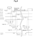
- FIGS. 2 and 4 will be referred to, and the operation of the leakage detecting means 100 will be explained.
- the leakage detecting means 100 is connected to both ends of the power storage element (1a to 40d) via the terminal T102 and the terminal T101, and is grounded to the vehicle body via the terminal T103.
- the earth leakage detecting means compares the current flowing between the terminal T101 and the grounding terminal T103 with the current flowing between the terminal T102 and the grounding terminal T103.
- the earth leakage detecting means is configured to output the larger current as an earth leakage detecting value from the terminal T100 to the control means 200.
- the leakage detection value is 0A.
- the human body touches the positive electrode side of the power storage element 40d, that is, the T101 side a leakage current is detected between the terminal T102 and the ground terminal T103. This is because the resistance value of the human body is about 5 K ⁇ .
- the leakage detection means 100 has a leakage detection value [ILeak] of 0A in the dead time period [Td1].
- the switching means S1a and S2a are turned off, and all the switching means including the switching means S1a and S2a are turned off.
- the leakage detection value [ILeak] in the leakage detection means 100 becomes larger than 0A.
- the dead time period [Td2] when the human body touches the high voltage portion while the switching means S1b and S3a are ON, all the switching means including the switching means S1b and S3a are turned OFF.
- the control means 200 inputs the leakage detection value [ILeak] to the terminal T200 of the control means 200 via the terminal T100 of the leakage detection means 100.
- the control means 200 detects that the [ILeak] is equal to or higher than the predetermined value [ILth]
- the control means 200 turns off the cutoff means 500 and the cutoff means 501 during the [Toff] period, as shown in FIG. 4 ,
- the time [Toff] is set to infinity, and after that, the cutoff means 500, 501 may remain off.
- the [Toff] is set to, for example, about 0.5 seconds, and the cutoff means 500 and 501 may be turned on again.
- the leakage detection value [ILeek] of the leakage detection means 100 in the dead time period [Tdn] exceeds [ILth] when the cutoff means 500 and 501 are turned on again, it is determined that the human body is still in contact with the high voltage circuit. Then, as shown by the broken line showing the action of the cutoff means 500 and 501 in FIG. 4 , the cutoff means 500 and 501 are turned off again to repeat on and off.
- the cutoff means 500 and 501 When the cutoff means 500 and 501 are turned on again, if the leakage detection value [ILeek] of the leakage detection means 100 in the dead time period [Tdn] is less than [ILth], it is determined that the human body is not in contact with the high voltage circuit. As shown by the solid line showing the operation of the cutoff means 500 and 501 in FIG. 4 , the cutoff means 500 and 501 hold the on state and restart the supply of electric power to the high voltage load device 400.
- the cutoff means 500 and 501 Since the high voltage power supply supplied to the outside from the power storage elements 1a to 40d is cut off by the cutoff means 500 and 501, the high voltage current does not flow through the human body and electric shock can be prevented.
- a housing By surrounding the vehicle power supply device 1 with a housing (not shown), it is possible to prevent a human body from touching the inside of the vehicle power supply device 1 and receiving an electric shock.
- the power generation means limits the charging voltage of the power storage element.
- the power generation means limits the charging voltage so that the voltage in which the entire node of the power storage element (1a to 40d) is connected in series becomes a predetermined maximum value.
- the current consumption of the electric load 300 is not constant, and may change significantly in a short time depending on the operating state of the driver, for example, as in the case of electric power steering.
- the switching means S1a to S40b are controlled by the control means 200 and the first group node to the 40th group node of the power storage element are switched at equal intervals, a difference may occur in the charging state of each group node.
- control means 200 monitors the voltage of each group node of the power storage element via the terminals (T201, T202, T203 to T239, T240) shown in FIG. 5 .
- the control means 200 preferentially connects the high voltage group node to the electric load 300. Then, the control means 200 prevents the low voltage group node from being connected to the electric load 300.
- the control means 200 selectively switches the storage element group (group node) to be discharged. As a result, the charging state of each power storage element group (group node) can be kept substantially uniform.
- the control means 200 monitors the voltage of each group node of the power storage element via the terminals T (201, T202, T203 to T239, T240) shown in FIG. 5 .
- the control means 200 sets a long period during which the switching means is ON for the high voltage group node.
- the control means 200 sets a short period during which the switching means is turned ON for the low voltage group node. In this way, (Ton1 to Ton40) can be individually calculated and controlled from the charge amount of the power storage element group (group node) and the current value flowing through the electric load 300. As a result, each power storage element group (group node) is maintained in a substantially uniform charging state.
- the period [Ton] is a period in which any two of the switching means S1a to S40b shown in FIG. 4 are ON.
- the detection is performed depending on whether or not the leakage detection value of the leakage detection means 100 in the dead time period [Td] at the moment when any of the two ON switching means is turned OFF is [ILth] or more and the cutoff means 500,801 are turned OFF. Therefore, the maximum time for the electric shock current to actually flow to the human body is [Ton].
- the electric shock current determined by the voltage value of the high voltage power supply by the power storage elements 1a to 40d and the resistance value of the human body and the human body reaction expected from the duration thereof are within the range that is harmless to the human body.
- the duration is determined by the [Ton] time. Generally, when the current value is 30 mA and the electric shock time is 0.1 sec or less, it is said that there is no fatal human reaction.
- the maximum value of the product of the electric shock current and the electric shock time is 0.003 amperes seconds in order to suppress the reaction to a safe human body.
- the maximum electric shock current is 100 mA from the voltage value of the high voltage power supply of 480 V and the human body resistance of 5 K ⁇ . From this assumption, the electric shock time without harm to the human body is calculated to be 0.03 sec or less. Therefore, the maximum value of the period [Ton] during which any two of the switching means S1a to S40b are ON is set to 0.001 sec, which is a small value with sufficient margin.
- a temporary leakage current may flow.
- the temporary leakage current is caused by a leak of a mounted electronic component, a malfunction of an insulating portion, vibration during traveling, or the like.
- the power supply from the high voltage power source to the high voltage load device 400 is completely stopped by the action of the control means 200, the function of each part may be lost while the vehicle is running, which may be dangerous.
- the cutoff means 500,501 are turned OFF. This state is maintained for 0.5 seconds or longer. After that, the cutoff means 500,501repeat the operation of turning ON.
- the power supply from the high voltage power supply to the high voltage load device 400 is resumed.
- the vehicle function can be restored, and driving safety can be maintained.
- the state in which the cutoff means 500,501 are OFF is set to 0.5 seconds or longer.
- the control means 200 keeps the cutoff means 500,501 OFF for 0.5 seconds or longer. After that, the switching means repeats the operation of turning ON the cutoff means 500,501. At this time, the energization time [Ton] after restarting the operation is shortened in inverse proportion to the voltage value of the high voltage power supply by the power storage elements 1a to 40d. Alternatively, it is desirable that the energization time [Ton] is shortened in inverse proportion to the leakage current value detected by the leakage detection means 100.
- the leakage is not caused by the vehicle but is an electric shock of the human body
- the higher the voltage of the high voltage power supply the shorter the energization time to the human body.
- the larger the electric shock current of the human body the shorter the energization time to the human body. It is more secure.
- the control means 200 switches the switching means (Sla to S40b) and switches each group node of the power storage element (1a to 40d). This switching cycle will be described with reference to FIG. 10 .
- control means 200 switches each group node in the cycle [T] to supply a predetermined low voltage power supply to the electric load 300. Further, it is assumed that the power generation means (not shown) is constantly charging so that the total voltage of the power storage elements (1a to 40d) connected in series becomes a predetermined value.
- the first group node shown in FIG. 10 can be given as an example.
- the current flowing through the electric load 300 causes the first group node to be in a discharged state and the charging voltage drops.
- the charging current is supplied from the power generation means so that the total voltage of all the power storage elements 1a to 40d becomes constant, the voltage changes in the increasing direction in the group node not selected.
- the difference between the maximum voltage and the minimum voltage at the specific group node at this time is the so-called charge / discharge depth. As the width of the charge / discharge depth increases, the life of the power storage element decreases.
- the time [Ton] is shortened.
- the time [Ton] in which the power storage element group (group node) is selectively connected to the electric load 300 by the control means 200 is shortened.
- the control cycle [T] that goes around the selection of all the power storage element groups (group nodes) should be shortened.
- the current [I] increases as the voltage [V] across the switching means decreases with the ON operation when the switching means is in the open state.
- switching loss occurs in the switching means S1a to S40b.
- the voltage [VL] applied to the electric load 300 during the dead time [Td] period shown in FIG. 3 becomes 0V during the period when all the switching means (Sla to S40b) are OFF. Therefore, since the power supplied to the electric load 300 is momentarily interrupted, there is a problem that the low voltage vehicle electric load is momentarily stopped.
- the capacitor 310 is arranged in parallel with the electric load 300.
- the voltage charged in the capacitor 310 continues to be supplied to the electric load 300.
- the voltage [VL] does not drop to 0V, and can be limited to a slight voltage drop from the peak voltage as shown by the broken line [VLa] shown in FIG. 3 .
- the amount of voltage drop in this case is determined by the current flowing through the electric load 300, the capacity of the capacitor 310, and the dead time [Td].
- the dead time [Td] and the current flowing through the electric load 300 are fixed, the larger the capacity of the capacitor 310, the smaller the amount of decrease in [VLa] can be.
- the amount of drop in [VLa] is determined by the capacity of the capacitor 310, the dead time [Td], and the current value flowing through the electric load 300. Therefore, by adjusting the capacity of the capacitor 310 and shortening the dead time [Td], the amount of drop of the [VLa] can be reduced. Needless to say this.
- the total voltage of the power storage elements connected in series is 12V, and the voltage of the capacitor 310 is approximately 12V.
- the total voltage of the power storage elements connected in series of 12V is a value at the group node of the power storage elements to which any switching means is turned ON and connected. From this, the voltage across the switching means can be set to approximately 0V when the switching means is in the open state. As shown in FIG. 9 , the switching loss in this case is such that the loss I ⁇ V becomes the minimum because the current I increases while the voltage V remains approximately 0V.
- the voltage of one group node of the power storage element is output as the voltage supplied to the electric load 300. It is utilized that the capacitor 310 holds the voltage of the group node. If the voltage of each group node is the same, the voltage of each group node when switching all the group nodes and the voltage of the electric load 300 (capacitor 310) are the same. The operation of the switching means is so-called [ZVS] (known zero volt switching), and theoretically no switching loss is generated.
- the heat loss generated by the switching element used for stepping down is extremely reduced.
- the power conversion efficiency was 99.5%.
- the heat sink is no longer required, which makes it possible to significantly reduce the system cost.
- the control means 200 does not stop the power supply to the electric load 300 due to the detection of the leakage current caused by the vehicle.
- the cutoff means 500,501 are all held OFF state. For example, hold for 0.5 seconds (predetermined time) or more. After that, the switching means repeats the operation of turning ON the the cutoff means 500,501 again.
- the power supply from the high voltage power supply to the high voltage load device 400 is stopped for 0.5 seconds. It is preferable that the capacitor (not shown) has a sufficient capacitance is placed in parallel so that the specified voltage can be supplied from the capacitor to the high voltage load device 400 even during the stop period.
- capacitors (601, 602 to 640) are connected at both ends of each power storage element group (group node) formed by connecting four nodes in series among the power storage elements 1a to 40d.
- the power storage element has an equivalent series resistance value of several tens of m ⁇ as an internal resistance (not shown) when, for example, a lithium ion battery is adopted. Therefore, in the case of four power storage elements connected in series in one group node in the present embodiment, each group node of the power storage element has an internal resistance of about 100 m ⁇ .
- the voltage [VL] of the electric load 300 rises when one of the switching means is turned ON after the dead time [Td] is terminated.
- the electric time constant of the rising portion is represented by the product of the capacitance of the capacitor 310 and the above-mentioned internal resistance.
- the rising waveform [VLb] of [VL] has a large time constant and the low voltage state continues for a long time. Further, since this is repeated in the period [T], it becomes a factor that the average value of the voltage supplied to the electric load 300 decreases. It is desirable that the time constant be as small as possible.
- the equivalent series resistance of a capacitor as a capacitance element is as small as several m ⁇ . Therefore, if a capacitor (601, 602 to 640) is connected in parallel with each group node of the power storage element as in the present embodiment, the internal resistance of the power storage element is apparently reduced. As shown in FIG. 3 , the rising waveform [VLc] of [VL] when the capacitor 310 is charged by the internal resistance has a small time constant and the low voltage state becomes short. Since this is repeated in the period [T], the decrease in the average value of the voltage supplied to the electric load 300 is small, and the accuracy of the voltage supplied to the electric load 300 is improved.
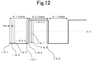
- FIG. 12 is referenced. Since the basic configuration is similar to the above-described embodiment, the figure showing the configuration in this embodiment is omitted.
- the power storage element 180 lithium ion batteries having a cell voltage of 3V unit are connected in series, and the total voltage is set to 540V.
- the 60 power storage elements are regarded as one group node, and the whole is divided into three group nodes (G1 to G3).
- the voltage of each group node is switched every 1 ms by the switching means and supplied to the commercial power supply load.
- the selected group node is G1.
- the switching means is operated to connect to the commercial power load.
- the polarity of the power storage element group (group node) is reversed.
- the high voltage power supply is formed by connecting power storage elements in series.
- a predetermined power storage element group (group node) from the high voltage power source to a low voltage electric load, power conversion from high voltage to low voltage can be performed.
- the power storage element group (group node) at high speed, the charge / discharge depth of the power storage element is reduced and the life is improved.
- the switching loss of the switching means for switching can be made substantially zero. It has an excellent feature that the weight and cost of the member required for heat dissipation of the switching element can be significantly improved.
- a dangerous human reaction can be suppressed even when the human body touches the high voltage power supply circuit portion without using means such as an isolated DC-DC converter.
- the voltage of the electric storage means can be boosted and supplied to the electric load.
- a capacitor constitutes a node and by charging each node with the voltage of the power storage element, it is configured to take out the boosted power from the capacitors connected in series.
Landscapes
- Engineering & Computer Science (AREA)
- Power Engineering (AREA)
- Life Sciences & Earth Sciences (AREA)
- Sustainable Development (AREA)
- Sustainable Energy (AREA)
- Transportation (AREA)
- Mechanical Engineering (AREA)
- Charge And Discharge Circuits For Batteries Or The Like (AREA)
- Electric Propulsion And Braking For Vehicles (AREA)
- Emergency Protection Circuit Devices (AREA)
Claims (15)
- Dispositif d'alimentation électrique pour véhicule, comprenant :une charge électrique qui fonctionne à une basse tension prédéterminée ;une alimentation électrique haute tension qui obtient une alimentation électrique CC haute tension en connectant en série une pluralité d'éléments de stockage d'énergie constituant chaque noeud qui fournit ladite basse tension prédéterminée ;un dispositif de charge haute tension connecté à l'alimentation électrique haute tension via un faisceau de câbles ;une pluralité de moyens de commutation prévus en correspondance avec chaque noeud qui fournit la basse tension prédéterminée à la charge électrique ;un moyen de commande, dans lequel le moyen de commande fournit une tension en allumant le moyen de commutation pour fournir une tension à partir d'au moins un noeud et en éteignant le moyen de commutation pour fournir une tension à partir d'un autre noeud, après avoir défini une période de temps mort pour éteindre tous les moyens de commutation d'un seul coup, en répétant séquentiellement la commande d'allumage du moyen de commutation du noeud qui fournit la tension suivante et d'extinction du moyen de commutation qui fournit la tension à partir de l'autre noeud, la tension est fournie à partir de tous les éléments de stockage ;un moyen de coupure pour couper un circuit électrique entre l'alimentation électrique haute tension et le dispositif de charge haute tension ; etun moyen de détection de fuite qui détecte un courant de fuite entre l'alimentation électrique haute tension et un potentiel de masse et envoie un signal audit moyen de commande,dans lequel le moyen de commande détermine le signal transmis par le moyen de détection de fuite pendant la période de temps mort lorsque la pluralité de moyens de commutation sont tous désactivés, et, lorsque le courant de fuite est supérieur ou égal à un courant prédéterminé, les moyens de coupure sont maintenus désactivés pendant une période de temps prédéterminée.
- Dispositif d'alimentation électrique pour véhicule selon la revendication 1, dans lequel
dans ladite alimentation électrique haute tension, une pluralité d'éléments de stockage d'énergie constituant le noeud dont n (n : nombre naturel) pièces forment la basse tension prédéterminée sont connectés en série (n x N (N : nombre naturel)), et une source d'alimentation CC ayant une haute tension N fois la basse tension prédéterminée peuvent être obtenues. - Dispositif d'alimentation électrique pour véhicule selon la revendication 1, dans lequel
ledit moyen de commande commande les moyens de commutation de manière à changer périodiquement une pluralité de noeuds sélectionnés. - Dispositif d'alimentation électrique pour véhicule selon la revendication 3, dans lequel
ledit moyen de commande détermine un noeud à sélectionner de sorte que les états de charge/décharge de la pluralité d'éléments de stockage d'énergie deviennent sensiblement uniformes. - Dispositif d'alimentation électrique pour véhicule selon la revendication 3, dans lequel
ledit moyen de commande détermine un temps de maintien sélectif de chaque noeud de sorte que les états de charge/décharge de la pluralité d'éléments de stockage d'énergie deviennent sensiblement uniformes. - Dispositif d'alimentation électrique pour véhicule selon l'une quelconque des revendications 1 à 5, dans lequel
un temps de connexion de l'un quelconque des noeuds à ladite charge électrique par ledit moyen de commutation est défini de manière à ce qu'un temps pendant lequel le courant de fuite circule de l'alimentation électrique haute tension vers le corps humain soit inférieur à un temps pendant lequel un accident de choc électrique dans le corps humain se produit. - Dispositif d'alimentation électrique pour véhicule selon la revendication 6, dans lequel
le temps de connexion de l'un quelconque des noeuds à ladite charge électrique par ledit moyen de commutation est défini de manière à être un temps qui est inversement proportionnel à la valeur de tension de l'alimentation électrique haute tension, ou un temps qui est inversement proportionnel à la valeur de courant détectée par le moyen de détection de fuite. - Dispositif d'alimentation électrique pour véhicule selon l'une quelconque des revendications 1 à 7, dans lequel
ledit moyen de commande fixe le moyen de coupure à un état désactivé lorsque la valeur de détection de fuite dudit moyen de détection de fuite est supérieure ou égale à une valeur de courant prédéterminée. - Dispositif d'alimentation électrique pour véhicule selon l'une quelconque des revendications 1 à 7, dans lequel
ledit moyen de commande maintient un état dans lequel les moyens de coupure sont désactivés pendant un temps prédéterminé lorsque la valeur de détection de fuite du moyen de détection de fuite est supérieure ou égale à une valeur de courant prédéterminée, et après cela, répète à nouveau l'opération dans laquelle les moyens de coupure sont activés. - Dispositif d'alimentation électrique pour véhicule selon l'une quelconque des revendications 1 à 9, dans lequel
ledit moyen de commande commande ledit moyen de commutation de manière à ce qu'un produit d'une période dans laquelle chaque noeud et la charge électrique sont connectés et de la valeur de détection de fuite du moyen de détection de fuite soit inférieur ou égal à 0,003 ampère × 1 seconde. - Dispositif d'alimentation électrique pour véhicule selon l'une quelconque des revendications 1 à 10, dans lequel
ledit moyen de commande définit un cycle de commutation d'un noeud sélectionné par ledit moyen de commutation à une valeur inférieure ou égale à une valeur prédéterminée de sorte qu'une ampleur d'une profondeur de charge/décharge dans chaque noeud de l'élément de stockage d'énergie soit inférieure ou égale à une valeur prédéterminée. - Dispositif d'alimentation électrique pour véhicule selon l'une quelconque des revendications 1 à 11, dans lequel
un condensateur est connecté en parallèle avec la charge électrique. - Dispositif d'alimentation électrique pour véhicule selon la revendication 12, dans lequel
ladite période de temps mort ou une valeur de capacité du condensateur est définie de sorte qu'une largeur de chute de tension appliquée à la charge électrique pendant la période de temps mort ne soit pas supérieure à une valeur prédéterm inée. - Dispositif d'alimentation électrique pour véhicule selon la revendication 12 ou 13, dans lequel
le condensateur est agencé en parallèle avec chaque noeud dudit élément de stockage d'énergie. - Dispositif d'alimentation électrique pour véhicule selon l'une quelconque des revendications 1 à 14, dans lequel
à partir de chaque noeud de la source d'alimentation haute tension qui obtient une alimentation électrique CC haute tension en connectant en série une pluralité d'éléments de stockage d'énergie, une alimentation CA est fournie à la charge électrique en inversant alternativement la polarité avec un côté potentiel et un côté inférieur à des périodes prédéterminées lorsque la charge électrique est connectée par le moyen de commutation.
Applications Claiming Priority (2)
| Application Number | Priority Date | Filing Date | Title |
|---|---|---|---|
| JP2020006560A JP7518333B2 (ja) | 2020-01-20 | 2020-01-20 | 車両用電源装置 |
| PCT/JP2020/045459 WO2021149371A1 (fr) | 2020-01-20 | 2020-12-07 | Alimentation électrique de véhicule |
Publications (3)
| Publication Number | Publication Date |
|---|---|
| EP4096040A1 EP4096040A1 (fr) | 2022-11-30 |
| EP4096040A4 EP4096040A4 (fr) | 2024-03-13 |
| EP4096040B1 true EP4096040B1 (fr) | 2025-02-12 |
Family
ID=76991682
Family Applications (1)
| Application Number | Title | Priority Date | Filing Date |
|---|---|---|---|
| EP20915202.4A Active EP4096040B1 (fr) | 2020-01-20 | 2020-12-07 | Alimentation électrique de véhicule |
Country Status (4)
| Country | Link |
|---|---|
| US (1) | US11951843B2 (fr) |
| EP (1) | EP4096040B1 (fr) |
| JP (1) | JP7518333B2 (fr) |
| WO (1) | WO2021149371A1 (fr) |
Cited By (1)
| Publication number | Priority date | Publication date | Assignee | Title |
|---|---|---|---|---|
| EP4489242A4 (fr) * | 2022-03-02 | 2026-04-01 | Imasen Electric Ind | Dispositif d'alimentation électrique de véhicule |
Families Citing this family (6)
| Publication number | Priority date | Publication date | Assignee | Title |
|---|---|---|---|---|
| JP7506300B2 (ja) * | 2020-03-13 | 2024-06-26 | 株式会社今仙電機製作所 | 車両用電源装置 |
| JP7560715B2 (ja) * | 2020-04-01 | 2024-10-03 | 株式会社今仙電機製作所 | 車両用電源装置 |
| JP7568908B2 (ja) * | 2020-11-02 | 2024-10-17 | 株式会社今仙電機製作所 | 車両用電源装置 |
| JP7578874B2 (ja) * | 2020-11-02 | 2024-11-07 | 株式会社今仙電機製作所 | 車両用電源装置 |
| US12556009B2 (en) * | 2021-01-19 | 2026-02-17 | The Boeing Company | Reconfigurable battery system for efficient charging and discharging |
| FR3123883B1 (fr) * | 2021-06-15 | 2025-05-09 | Ixblue | Dispositif et procédé de commande autonome d’un bateau |
Family Cites Families (10)
| Publication number | Priority date | Publication date | Assignee | Title |
|---|---|---|---|---|
| JP3307173B2 (ja) * | 1995-03-20 | 2002-07-24 | 松下電器産業株式会社 | 漏電検出装置 |
| JP2004248403A (ja) * | 2003-02-13 | 2004-09-02 | Sumitomo Electric Ind Ltd | 自動車用電源の接地検出機構 |
| JP2011155829A (ja) * | 2009-12-28 | 2011-08-11 | Sanyo Electric Co Ltd | バッテリシステムおよびそれを備えた電動車両 |
| JP5767077B2 (ja) * | 2011-10-24 | 2015-08-19 | 株式会社ケーヒン | 漏電検出装置 |
| US20140301000A1 (en) * | 2011-12-27 | 2014-10-09 | Hitachi, Ltd. | Battery System and Ground Fault Detecting Device |
| JP2013257211A (ja) * | 2012-06-12 | 2013-12-26 | Shin Meiwa Ind Co Ltd | 作業車両およびその漏電検知方法 |
| DE102014201348A1 (de) | 2014-01-27 | 2015-07-30 | Robert Bosch Gmbh | Verfahren zum Betrieb eines Bordnetzes |
| JP6761172B2 (ja) * | 2016-08-12 | 2020-09-23 | 株式会社今仙電機製作所 | 車両用電源装置 |
| JP7506300B2 (ja) * | 2020-03-13 | 2024-06-26 | 株式会社今仙電機製作所 | 車両用電源装置 |
| JP7560715B2 (ja) * | 2020-04-01 | 2024-10-03 | 株式会社今仙電機製作所 | 車両用電源装置 |
-
2020
- 2020-01-20 JP JP2020006560A patent/JP7518333B2/ja active Active
- 2020-12-07 WO PCT/JP2020/045459 patent/WO2021149371A1/fr not_active Ceased
- 2020-12-07 US US17/756,344 patent/US11951843B2/en active Active
- 2020-12-07 EP EP20915202.4A patent/EP4096040B1/fr active Active
Cited By (1)
| Publication number | Priority date | Publication date | Assignee | Title |
|---|---|---|---|---|
| EP4489242A4 (fr) * | 2022-03-02 | 2026-04-01 | Imasen Electric Ind | Dispositif d'alimentation électrique de véhicule |
Also Published As
| Publication number | Publication date |
|---|---|
| EP4096040A4 (fr) | 2024-03-13 |
| EP4096040A1 (fr) | 2022-11-30 |
| US20230001797A1 (en) | 2023-01-05 |
| JP2021114847A (ja) | 2021-08-05 |
| US11951843B2 (en) | 2024-04-09 |
| JP7518333B2 (ja) | 2024-07-18 |
| CN114788123A (zh) | 2022-07-22 |
| WO2021149371A1 (fr) | 2021-07-29 |
Similar Documents
| Publication | Publication Date | Title |
|---|---|---|
| US11951843B2 (en) | Power supply device for vehicle | |
| US11945313B2 (en) | Power supply device for vehicle | |
| US11949259B2 (en) | Power supply device for vehicle | |
| US11904706B2 (en) | Power supply device for vehicle | |
| EP4238805B1 (fr) | Dispositif source d'alimentation de véhicule | |
| US12109899B2 (en) | Power supply device for vehicle | |
| CN114788123B (en) | Power supply device for vehicle | |
| JP7748632B2 (ja) | 車両用電源装置 | |
| CN106160040B (zh) | 车用二次锂电池 | |
| JP2009177939A (ja) | 車両用電源装置 |
Legal Events
| Date | Code | Title | Description |
|---|---|---|---|
| STAA | Information on the status of an ep patent application or granted ep patent |
Free format text: STATUS: THE INTERNATIONAL PUBLICATION HAS BEEN MADE |
|
| PUAI | Public reference made under article 153(3) epc to a published international application that has entered the european phase |
Free format text: ORIGINAL CODE: 0009012 |
|
| STAA | Information on the status of an ep patent application or granted ep patent |
Free format text: STATUS: REQUEST FOR EXAMINATION WAS MADE |
|
| 17P | Request for examination filed |
Effective date: 20220520 |
|
| AK | Designated contracting states |
Kind code of ref document: A1 Designated state(s): AL AT BE BG CH CY CZ DE DK EE ES FI FR GB GR HR HU IE IS IT LI LT LU LV MC MK MT NL NO PL PT RO RS SE SI SK SM TR |
|
| DAV | Request for validation of the european patent (deleted) | ||
| DAX | Request for extension of the european patent (deleted) | ||
| A4 | Supplementary search report drawn up and despatched |
Effective date: 20240212 |
|
| RIC1 | Information provided on ipc code assigned before grant |
Ipc: B60L 58/21 20190101ALI20240206BHEP Ipc: B60L 58/12 20190101ALI20240206BHEP Ipc: H02J 7/00 20060101ALI20240206BHEP Ipc: B60L 3/00 20190101ALI20240206BHEP Ipc: H02H 3/16 20060101AFI20240206BHEP |
|
| GRAP | Despatch of communication of intention to grant a patent |
Free format text: ORIGINAL CODE: EPIDOSNIGR1 |
|
| STAA | Information on the status of an ep patent application or granted ep patent |
Free format text: STATUS: GRANT OF PATENT IS INTENDED |
|
| INTG | Intention to grant announced |
Effective date: 20241015 |
|
| GRAS | Grant fee paid |
Free format text: ORIGINAL CODE: EPIDOSNIGR3 |
|
| GRAA | (expected) grant |
Free format text: ORIGINAL CODE: 0009210 |
|
| STAA | Information on the status of an ep patent application or granted ep patent |
Free format text: STATUS: THE PATENT HAS BEEN GRANTED |
|
| AK | Designated contracting states |
Kind code of ref document: B1 Designated state(s): AL AT BE BG CH CY CZ DE DK EE ES FI FR GB GR HR HU IE IS IT LI LT LU LV MC MK MT NL NO PL PT RO RS SE SI SK SM TR |
|
| REG | Reference to a national code |
Ref country code: GB Ref legal event code: FG4D |
|
| REG | Reference to a national code |
Ref country code: CH Ref legal event code: EP |
|
| REG | Reference to a national code |
Ref country code: DE Ref legal event code: R096 Ref document number: 602020046147 Country of ref document: DE |
|
| REG | Reference to a national code |
Ref country code: IE Ref legal event code: FG4D |
|
| REG | Reference to a national code |
Ref country code: NL Ref legal event code: MP Effective date: 20250212 |
|
| PG25 | Lapsed in a contracting state [announced via postgrant information from national office to epo] |
Ref country code: RS Free format text: LAPSE BECAUSE OF FAILURE TO SUBMIT A TRANSLATION OF THE DESCRIPTION OR TO PAY THE FEE WITHIN THE PRESCRIBED TIME-LIMIT Effective date: 20250512 |
|
| PG25 | Lapsed in a contracting state [announced via postgrant information from national office to epo] |
Ref country code: FI Free format text: LAPSE BECAUSE OF FAILURE TO SUBMIT A TRANSLATION OF THE DESCRIPTION OR TO PAY THE FEE WITHIN THE PRESCRIBED TIME-LIMIT Effective date: 20250212 |
|
| PG25 | Lapsed in a contracting state [announced via postgrant information from national office to epo] |
Ref country code: PL Free format text: LAPSE BECAUSE OF FAILURE TO SUBMIT A TRANSLATION OF THE DESCRIPTION OR TO PAY THE FEE WITHIN THE PRESCRIBED TIME-LIMIT Effective date: 20250212 |
|
| PG25 | Lapsed in a contracting state [announced via postgrant information from national office to epo] |
Ref country code: ES Free format text: LAPSE BECAUSE OF FAILURE TO SUBMIT A TRANSLATION OF THE DESCRIPTION OR TO PAY THE FEE WITHIN THE PRESCRIBED TIME-LIMIT Effective date: 20250212 |
|
| REG | Reference to a national code |
Ref country code: LT Ref legal event code: MG9D |
|
| PG25 | Lapsed in a contracting state [announced via postgrant information from national office to epo] |
Ref country code: NO Free format text: LAPSE BECAUSE OF FAILURE TO SUBMIT A TRANSLATION OF THE DESCRIPTION OR TO PAY THE FEE WITHIN THE PRESCRIBED TIME-LIMIT Effective date: 20250512 Ref country code: IS Free format text: LAPSE BECAUSE OF FAILURE TO SUBMIT A TRANSLATION OF THE DESCRIPTION OR TO PAY THE FEE WITHIN THE PRESCRIBED TIME-LIMIT Effective date: 20250612 |
|
| PG25 | Lapsed in a contracting state [announced via postgrant information from national office to epo] |
Ref country code: NL Free format text: LAPSE BECAUSE OF FAILURE TO SUBMIT A TRANSLATION OF THE DESCRIPTION OR TO PAY THE FEE WITHIN THE PRESCRIBED TIME-LIMIT Effective date: 20250212 |
|
| PG25 | Lapsed in a contracting state [announced via postgrant information from national office to epo] |
Ref country code: HR Free format text: LAPSE BECAUSE OF FAILURE TO SUBMIT A TRANSLATION OF THE DESCRIPTION OR TO PAY THE FEE WITHIN THE PRESCRIBED TIME-LIMIT Effective date: 20250212 |
|
| PG25 | Lapsed in a contracting state [announced via postgrant information from national office to epo] |
Ref country code: LV Free format text: LAPSE BECAUSE OF FAILURE TO SUBMIT A TRANSLATION OF THE DESCRIPTION OR TO PAY THE FEE WITHIN THE PRESCRIBED TIME-LIMIT Effective date: 20250212 Ref country code: PT Free format text: LAPSE BECAUSE OF FAILURE TO SUBMIT A TRANSLATION OF THE DESCRIPTION OR TO PAY THE FEE WITHIN THE PRESCRIBED TIME-LIMIT Effective date: 20250612 |
|
| PG25 | Lapsed in a contracting state [announced via postgrant information from national office to epo] |
Ref country code: BG Free format text: LAPSE BECAUSE OF FAILURE TO SUBMIT A TRANSLATION OF THE DESCRIPTION OR TO PAY THE FEE WITHIN THE PRESCRIBED TIME-LIMIT Effective date: 20250212 Ref country code: GR Free format text: LAPSE BECAUSE OF FAILURE TO SUBMIT A TRANSLATION OF THE DESCRIPTION OR TO PAY THE FEE WITHIN THE PRESCRIBED TIME-LIMIT Effective date: 20250513 |
|
| REG | Reference to a national code |
Ref country code: AT Ref legal event code: MK05 Ref document number: 1767037 Country of ref document: AT Kind code of ref document: T Effective date: 20250212 |
|
| PG25 | Lapsed in a contracting state [announced via postgrant information from national office to epo] |
Ref country code: SE Free format text: LAPSE BECAUSE OF FAILURE TO SUBMIT A TRANSLATION OF THE DESCRIPTION OR TO PAY THE FEE WITHIN THE PRESCRIBED TIME-LIMIT Effective date: 20250212 |
|
| PG25 | Lapsed in a contracting state [announced via postgrant information from national office to epo] |
Ref country code: SM Free format text: LAPSE BECAUSE OF FAILURE TO SUBMIT A TRANSLATION OF THE DESCRIPTION OR TO PAY THE FEE WITHIN THE PRESCRIBED TIME-LIMIT Effective date: 20250212 |
|
| PG25 | Lapsed in a contracting state [announced via postgrant information from national office to epo] |
Ref country code: DK Free format text: LAPSE BECAUSE OF FAILURE TO SUBMIT A TRANSLATION OF THE DESCRIPTION OR TO PAY THE FEE WITHIN THE PRESCRIBED TIME-LIMIT Effective date: 20250212 |
|
| PG25 | Lapsed in a contracting state [announced via postgrant information from national office to epo] |
Ref country code: IT Free format text: LAPSE BECAUSE OF FAILURE TO SUBMIT A TRANSLATION OF THE DESCRIPTION OR TO PAY THE FEE WITHIN THE PRESCRIBED TIME-LIMIT Effective date: 20250212 |
|
| PG25 | Lapsed in a contracting state [announced via postgrant information from national office to epo] |
Ref country code: AT Free format text: LAPSE BECAUSE OF FAILURE TO SUBMIT A TRANSLATION OF THE DESCRIPTION OR TO PAY THE FEE WITHIN THE PRESCRIBED TIME-LIMIT Effective date: 20250212 |
|
| PG25 | Lapsed in a contracting state [announced via postgrant information from national office to epo] |
Ref country code: EE Free format text: LAPSE BECAUSE OF FAILURE TO SUBMIT A TRANSLATION OF THE DESCRIPTION OR TO PAY THE FEE WITHIN THE PRESCRIBED TIME-LIMIT Effective date: 20250212 Ref country code: CZ Free format text: LAPSE BECAUSE OF FAILURE TO SUBMIT A TRANSLATION OF THE DESCRIPTION OR TO PAY THE FEE WITHIN THE PRESCRIBED TIME-LIMIT Effective date: 20250212 |
|
| PG25 | Lapsed in a contracting state [announced via postgrant information from national office to epo] |
Ref country code: RO Free format text: LAPSE BECAUSE OF FAILURE TO SUBMIT A TRANSLATION OF THE DESCRIPTION OR TO PAY THE FEE WITHIN THE PRESCRIBED TIME-LIMIT Effective date: 20250212 |
|
| PG25 | Lapsed in a contracting state [announced via postgrant information from national office to epo] |
Ref country code: SK Free format text: LAPSE BECAUSE OF FAILURE TO SUBMIT A TRANSLATION OF THE DESCRIPTION OR TO PAY THE FEE WITHIN THE PRESCRIBED TIME-LIMIT Effective date: 20250212 |
|
| REG | Reference to a national code |
Ref country code: DE Ref legal event code: R097 Ref document number: 602020046147 Country of ref document: DE |
|
| PLBE | No opposition filed within time limit |
Free format text: ORIGINAL CODE: 0009261 |
|
| STAA | Information on the status of an ep patent application or granted ep patent |
Free format text: STATUS: NO OPPOSITION FILED WITHIN TIME LIMIT |
|
| PGFP | Annual fee paid to national office [announced via postgrant information from national office to epo] |
Ref country code: DE Payment date: 20251028 Year of fee payment: 6 |
|
| PGFP | Annual fee paid to national office [announced via postgrant information from national office to epo] |
Ref country code: FR Payment date: 20251110 Year of fee payment: 6 |
|
| 26N | No opposition filed |
Effective date: 20251113 |