EP4096162A1 - Verfahren zur gemeinsamen erzeugung und übertragung von systeminformationen für disaggregierte ran-systeme - Google Patents
Verfahren zur gemeinsamen erzeugung und übertragung von systeminformationen für disaggregierte ran-systeme Download PDFInfo
- Publication number
- EP4096162A1 EP4096162A1 EP21175908.9A EP21175908A EP4096162A1 EP 4096162 A1 EP4096162 A1 EP 4096162A1 EP 21175908 A EP21175908 A EP 21175908A EP 4096162 A1 EP4096162 A1 EP 4096162A1
- Authority
- EP
- European Patent Office
- Prior art keywords
- ran
- infrastructure
- rus
- ies
- information
- Prior art date
- Legal status (The legal status is an assumption and is not a legal conclusion. Google has not performed a legal analysis and makes no representation as to the accuracy of the status listed.)
- Granted
Links
Images

Classifications
-
- H—ELECTRICITY
- H04—ELECTRIC COMMUNICATION TECHNIQUE
- H04W—WIRELESS COMMUNICATION NETWORKS
- H04W24/00—Supervisory, monitoring or testing arrangements
- H04W24/02—Arrangements for optimising operational condition
-
- H—ELECTRICITY
- H04—ELECTRIC COMMUNICATION TECHNIQUE
- H04L—TRANSMISSION OF DIGITAL INFORMATION, e.g. TELEGRAPHIC COMMUNICATION
- H04L41/00—Arrangements for maintenance, administration or management of data switching networks, e.g. of packet switching networks
- H04L41/04—Network management architectures or arrangements
- H04L41/042—Network management architectures or arrangements comprising distributed management centres cooperatively managing the network
-
- H—ELECTRICITY
- H04—ELECTRIC COMMUNICATION TECHNIQUE
- H04L—TRANSMISSION OF DIGITAL INFORMATION, e.g. TELEGRAPHIC COMMUNICATION
- H04L41/00—Arrangements for maintenance, administration or management of data switching networks, e.g. of packet switching networks
- H04L41/34—Signalling channels for network management communication
-
- H—ELECTRICITY
- H04—ELECTRIC COMMUNICATION TECHNIQUE
- H04W—WIRELESS COMMUNICATION NETWORKS
- H04W48/00—Access restriction; Network selection; Access point selection
- H04W48/18—Selecting a network or a communication service
-
- H—ELECTRICITY
- H04—ELECTRIC COMMUNICATION TECHNIQUE
- H04W—WIRELESS COMMUNICATION NETWORKS
- H04W80/00—Wireless network protocols or protocol adaptations to wireless operation
- H04W80/08—Upper layer protocols
- H04W80/12—Application layer protocols, e.g. WAP [Wireless Application Protocol]
Definitions
- This invention relates to methods for generation and transmission of System Information, SI, in a Mobile telecommunication Network, MN, and MNs thereof.
- Open Radio Access Network relates to a disaggregated approach to deploying Radio Access Networks (RANs) built on cloud native principles.
- the main objective of O-RAN is to allow a disaggregation of the RAN layer of telecom networks to achieve a disaggregated system comprised of: Common Infrastructure layer; differentiated RAN software running on top of said O-RAN infrastructure; and standardized interfaces between components within the RAN.
- the common Infrastructure layer (similar to what cloud providers provide to current software application) is where the RAN software can run on.
- the common Infrastructure layer is referred to as "Infrastructure layer”.
- RAN software running on top of said O-RAN infrastructure (i.e. the application layer), will be referred to in the foregoing specification as "RAN software”.
- the infrastructure and application layers are completely decoupled. That is, from the application perspective, the underlying infrastructure is not in any way visible. Neither directly (typically not desirable) nor indirectly (e.g. whether certain services or features may be available).
- touchpoints There are several touchpoints between the application and infrastructure layer and the tighter both layers have to interwork, the more touchpoints that are required. Examples of such touchpoints in current state of the art are whether the infrastructure provides specific hardware capabilities (e.g. accelerator modules) or the exact services a runtime environment provides (e.g. container, virtualization environment).
- the infrastructure provides specific hardware capabilities (e.g. accelerator modules) or the exact services a runtime environment provides (e.g. container, virtualization environment).
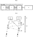
- FIG. 1 illustrates an example of the functional split of current mobile telecommunications systems (exemplified for the case of a 5G system).
- a UE 1 is connected to a Data Network (DN) 4 via a Core Network (CN) 3 and an Access Network (AN) 2, in this example a Radio Access Network (RAN)s.
- DN Data Network
- CN Core Network
- AN Access Network
- RAN Radio Access Network
- the ANs 2 are Radio Access Networks (RANs), which are ANs that are based on radio technologies (e.g. 5G New Radio, 5G NR).
- RANs Radio Access Networks
- 5G New Radio 5G NR
- Both the RAN 2 and the CN 3 are composed of several functional components.
- the RAN 2 is composed of gNBs and the CN 3 of Network Functions (NFs).
- the interface between the RAN 2 and the UE 1 is radio-based (in a 5GC, termed "Uu interface").
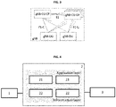
- FIG. 2 illustrates an example of the RAN and CN decomposition.
- FIG. 2 also depicts the several relevant interfaces between the following components as named within a 5G system: gNB-gNB: Xn interface; UE-gNB: Uu interface; and gNB-NF: NG interface.
- a current state of the art disaggregated RAN architecture is that defined by the O-RAN Alliance (Technical Specification: O-RAN Architecture Description; ORAN.WG1.O-RAN-Architecture-Description-v03.00).
- This architecture defines elements such as a cloud computing platform comprising a collection of physical infrastructure nodes that meet O-RAN requirements to host the relevant O-RAN functions (such as Near-RT RIC, O-CU-CP, O-CU-UP, and O-DU), supporting software components (such as Operating System, Virtual Machine Monitor, Container Runtime, etc.) and appropriate management and orchestration functions.
- the application layer follows a disaggregation trend, being the state of the art with 5G that a functional RAN node (gNB) is divided in two dimensions in CU/DU (central/distributed units) and CP/UP (control plane unit and user plane unit) (3GPP TS 38.401).
- gNB functional RAN node
- CU/DU central/distributed units
- CP/UP control plane unit and user plane unit
- FIG. 3 illustrates the overall architecture for separation of gNB-CU-CP and gNB-CU-UP as illustrated in 3GPP TS 38.401, 6.1.2.
- the present invention as described hereinafter, focuses on a disaggregated RAN, where the RAN is at least composed of a RU and a software component running on a computing platform.
- management components not part of the standardized functional components are typically part of gNB implementations and take care of, for example, management and/or Operation, Administration and Maintenance (OAM).
- OAM Operation, Administration and Maintenance
- FIG. 4 illustrates a disaggregated RAN deployment according to an example.
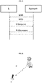
- the RAN software which is depicted as application layer, is composed of one or more software components 21 and runs on the infrastructure layer, the infrastructure layer being composed of infrastructure nodes 22.
- Other applications besides the RAN software, could run on the infrastructure layer.
- the service management and orchestration framework is part of the infrastructure layer, which is configured to manage the infrastructure nodes.
- SI acquisition As defined by 3GPP TS 38.331, the UE performs what is known as System Information (SI) acquisition (as defined by 3GPP TS 38.331). This entails the reception and processing of information broadcast be the RAN which aids the UE at characterizing the RAN system that it sees.
- SI System Information
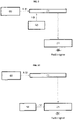
- FIG. 5 illustrates an exemplary functional view of the MIB and the SIB as defined by 3GPP TS 38.331.
- FIG. 6 illustrates a visual example of the broadcasting, from gNB to UE, of the System Information.
- the UE 1 receives System Information (SI) in the MIB and SIB1. Then, the UE 1 sends a request for system information to the network. Thereafter, the network sends to the UE 1 messages including the requested system information.
- SI System Information
- both the MIB and SIB contain information elements of different granularity.
- information elements that can be found in the System Information (SI) are: Frequency info for the uplink; Frequency band lists; Random Access Channel (RACH) parameters; PLMN IDs supported; whether specific services are supported (e.g. voice, UE onboarding, private networks); Access information (e.g. whether the cell is barred and whether only specific UEs may try to access the cell); service capabilities related to Core and/or IMS (e.g. VoNR support); etc.
- SI System Information
- the UE uses the information received from the MIB and SIB, as well as other information and local configuration, as input for algorithms used in e.g. network selection, mobility and steering/triggering other radio procedures.
- the common state-of-the-art principle is that the SI is sent via the so-called Broadcast Channel (BCH).
- BCH Broadcast Channel
- the Sl is broadcast using specific modulation and coding schemes that are not necessarily the same as those used for transmission of user data.
- FIG. 7 illustrates an exemplary flowchart of the generation of the radio signal.
- the RAN software component 21 on a disaggregated RAN deployment, the RAN software component 21 generates the Sl (as well as most data necessary to generate the radio signal,) and sends it via a fronthaul interface towards the Radio Unit (RU).
- the RU 23 is not relevant for generating the data itself but mainly performs only physical (PHY) layer functions.
- Radio Unit When deployed on O-RAN infrastructure, it is the RAN software that generates the signal being ultimately transmitted by the Radio Unit.
- the RAN is composed of RU, "functional rest” (RAN software) and a fronthaul interface between the two;
- the UE receives System Information (SIB/MIB) from the RAN.
- SIB/MIB System Information
- This information characterizes the RAN and 5G system behind it and is used by the UE for procedures such as network/cell selection and mobility; and the RAN software runs on an infrastructure layer.
- a disaggregated RAN deployment allows operational disaggregation, i.e. operational separation between the RAN infrastructure and application layers.
- SI System Information
- a Mobile telecommunication Network comprising a User Equipment, UE, and a Radio Access Network, RAN, the RAN being composed of one or more RAN nodes.
- the RAN comprises at least: an application layer comprising one or more RAN software components configured to run on one or more infrastructure nodes; an infrastructure layer comprising: one or more Radio Units, RUs, and infrastructure nodes; an infrastructure management entity configured to manage the infrastructure nodes and/or the one or more RUs; a fronthaul interface configured to provide a data connection between the one or more RAN software components and the one or more RUs; a radio interface configured to provide a data connection between the one or more RUs and the UE.
- the infrastructure management entity is configured to: generate System Information, SI, elements, SI IEs, relative to the infrastructure layer, I-SI IEs, and input the I-SI IEs to the one or more RAN software components.
- the one or more RAN software component is configured to generate SI composed of SI IEs relative to the RAN, where a SI IE is: a SI IE relative to the application layer, A-SI IE, wherein a A-SI IE is either: configured locally by the one or more RAN software components itself; and/or received, by the one or more RAN software components, from an Operations and Management System, OAM, entity; a I-SI IE inputted by the infrastructure management entity; and/or information derived from one or more A-SI IEs and/or one or more I-SI IEs.
- the one or more RAN software component is configured to transmit the generated Sl or information derived from the generated SI to the one or more RUs via the fronthaul interface.
- the one or more RUs is configured to use the information received from the RAN software to generate and transmit a radio signal comprising the SI IEs.
- the UE is configured to receive the radio signal transmitted by the one or more RUs.
- a Mobile telecommunication Network comprising a User Equipment, UE, and a Radio Access Network, RAN, the RAN being composed of one or more RAN nodes.
- the RAN comprises at least: an application layer comprising one or more RAN software components configured to run on one or more infrastructure nodes; an infrastructure layer comprising: one or more Radio Units, RUs; and infrastructure nodes; an infrastructure management entity configured to manage the infrastructure nodes and/or the one or more RUs; a fronthaul interface configured to provide a data connection between the one or more RAN software components and the one or more RUs; a radio interface configured to provide a data connection between the one or more RUs and the UE.
- the one or more RAN software components is configured to: generate System Information, SI, composed of SI information elements, SI IEs, comprising information relative to the application layer, A-SI, wherein the A-SI is either: configured locally by the one or more RAN software components itself and/or received, by the one or more RAN software components, from an Operations and Management System, OAM, entity; and transmit the generated SI or information derived from the generated SI to the one or more RUs via the fronthaul interface.
- the infrastructure management entity is configured to: generate information elements, IEs, relative to the infrastructure layer, I-SI IEs, and input the I-SI IEs to the one or more RUs.
- the one or more RUs are configured to generate and transmit a radio signal containing SI IEs composed of: the I-SI IEs; and/or the A-SI IES; and/or information derived from one or more A-SI IEs and/or one or more I-SI IEs.
- the UE is configured to receive the radio signal transmitted by the one or more RUs.
- the I-SI may comprise: information identifying an entity operating the infrastructure layer; and/or information relative to services being served by the infrastructure layer; and/or information relative to infrastructure load; and/or information relative to a nature of the software of the infrastructure layer; and/or information relative to a software version of the infrastructure layer; and/or information relative to connectivity of the infrastructure layer; and/or information relative to hardware capabilities of the infrastructure layer; and/or information relative to the availability of the infrastructure layer or infrastructure nodes.
- the UE may be configured to use the I-SI to: perform network selection, mobility, trigger specific services or trigger specific procedures within specific services.
- the I-SI may comprise one or more lEs referring to information from multiple infrastructure layers.
- the one or more RAN nodes may be configured to exchange I-SI information for steering UE mobility.
- SI System Information
- the method comprising the steps of: generating, by the infrastructure management entity, System Information, SI, Elements, SI IEs, relative to the infrastructure layer, I-SI IEs, and inputting the I-SI IEs to the one or more RAN software components; generating, by the one or more RAN software components, SI composed of SI IEs relative to the RAN, where a SI IE is: a SI IE relative to the application layer, A-SI IE, wherein a A-SI IE is either: configured locally by the one or more RAN software components itself; and/or received, by the one or more RAN software components, from an Operations and Management System, OAM, entity; a I-SI IE inputted by the infrastructure management entity; and/or information derived from one or more A-SI IEs and/or one or more I-SI IEs; transmitting, by the one or more RAN software components, the generated SI or information derived from the generated SI to the one or more RUs via the fronthaul
- SI System Information
- the method comprising the steps of: generating, by the one or more RAN software components, System Information, SI, composed of SI information elements, SI IEs, comprising information relative to the application layer, A-SI, wherein generating the A-SI is done by: locally configuring the A-SI by the one or more RAN software components itself and/or receiving, by the one or more RAN software components, from an Operations and Management System, OAM, entity; transmitting, by the one or more RAN software components, the generated Sl or information derived from the generated Sl to the one or more RUs via the fronthaul interface; generating, by the infrastructure management entity, SI information elements, IEs, relative to the infrastructure layer, I-SI IEs, and inputting the I-SI IEs to the one or more RUs; generating, by the one or more RUs, a radio signal comprising the SI; transmitting, by one or more RUs, the radio signal containing SI IEs composed of: the I-SI IEs;
- the I-SI may comprise: information identifying an entity operating the infrastructure layer; and/or information relative to services being served by the infrastructure layer; and/or information relative to infrastructure load; and/or information relative to a nature of the software of the infrastructure layer; and/or information relative to a software version of the infrastructure layer; and/or information relative to connectivity of the infrastructure layer; and/or information relative to hardware capabilities of the infrastructure layer.
- the method further comprises performing, by the UE network selection or mobility using the I-SI; and/or triggering, by the UE, specific services or procedures within specific services using the I-SI.
- the I-SI may comprise one or more lEs referring to information from multiple infrastructure layers.
- the method may further comprise exchanging, by the one or more RAN nodes, I-SI information for steering UE mobility.
- the present invention comprises a Mobile telecommunication Network, MN, comprising a User Equipment (UE) 1, a Radio Access Network (RAN) 2, and a Core Network (CN) 3 as depicted in FIG. 4 .
- MN Mobile telecommunication Network
- UE User Equipment
- RAN Radio Access Network
- CN Core Network
- the RAN is composed of one or more RAN nodes ( FIG. 5 only shows one RAN node).
- the RAN (or RAN nodes) comprises at least: an application layer comprising one or more RAN software components 21 configured to run on one or more infrastructure nodes 22; an infrastructure layer comprising: one or more Radio Units (RUs)(not shown) and the one or more infrastructure nodes 22; an infrastructure management entity (not shown) configured to manage the infrastructure nodes 22 and/or the one or more RUs; a fronthaul interface (not shown) configured to provide a data connection between the one or more RAN software components 21 and the one or more RUs; and a radio interface configured to provide a data connection between the one or more RUs and the UE 1.
- RUs Radio Units
- a fronthaul interface (not shown) configured to provide a data connection between the one or more RAN software components 21 and the one or more RUs
- a radio interface configured to provide a data connection between the one or more RUs and the UE
- SI IEs System Information elements
- I-IEs Infrastructure layer related SI
- the System Information comprises Application layer related SI (A-SI) information elements and Infrastructure layer related SI (I-SI) information elements.
- Example information elements that can be included as part of the I-SI are:
- the generation of the system information (SI) may be done by two different alternatives as illustrated by FIGs. 9 and 10 .
- the application layer generates the SI
- the infrastructure layer generates the SI.
- an infrastructure layer management entity 50 is configured to generate SI elements (SI IEs) relative to the infrastructure layer (I-SI IEs). Once generated, the infrastructure layer management entity 50 inputs the I-SI IEs to the one or more RAN software components 21.
- SI IEs SI elements
- I-SI IEs infrastructure layer
- the one or more RAN software components 21 Based on the above received inputs, the one or more RAN software components 21 generate Sl composed of SI IEs relative to the RAN.
- a SI IE may be a SI IE relative to the application layer, A-SI IE.
- a A-SI IE can be either: configured locally by the one or more RAN software components 21 itself.
- a A-SI IE may be received, by the one or more RAN software components 21, from an Operations and Management System, OAM, entity 60.
- a SI IE can be a I-SI IE as inputted by the infrastructure layer management entity 50.
- a SI IE instead of being a I-SI IE or A-SI IE, may be information derived from one or more A-SI IEs and/or one or more I-SI IEs.
- the one or more RAN software components 21 transmit the generated Sl or information derived from the generated SI to the one or more RUs 23 via the fronthaul interface.
- the one or more RUs 23 Based on the information received from the RAN software components 21, the one or more RUs 23 generate and transmit a radio signal comprising the SI IEs.
- the UE 1 receives the radio signal transmitted by the one or more RUs 23.
- the Infrastructure layer Management entity 50 may be the Service Management and Orchestration Framework and the fronthaul interface may be the O-FH.
- the Infrastructure layer Management entity 50 may be connected to the one or more RUs through a new interface touchpoint between the O-RAN layer and the application layer.
- the SI may be generated by the application layer as illustrated by FIG. 11.
- the one or more RAN software components 21 generate the Sl composed of SI IEs.
- the SI IEs comprise information relative to the application layer (A-SI) which can be either: configured locally by the one or more RAN software components 21 itself and/or received from an Operations and Management System, OAM, entity 60.
- A-SI application layer
- the one or more RAN software components 21 transmit the generated Sl or information derived from the generated Sl to the one or more RUs 23 via the fronthaul interface.
- the infrastructure layer management entity 50 By contrast to the embodiment of FIG. 9 , in FIG. 10 the infrastructure layer management entity 50 generates the lEs relative to the infrastructure layer (I-SI IEs) and inputs them to the one or more RUs 23.
- the radio signal contains SI IEs composed of: the I-SI IEs; and/or the A-SI IES; and/or information derived from one or more A-SI IEs and/or one or more I-SI IEs.
- the UE 1 receives the radio signal transmitted by the one or more RUs.
- the Infrastructure layer is also characterized by System Information (SI).
- SI System Information
- the UE 1 receives SI not only referring to the RAN but also to the infrastructure layer.
- the Infrastructure layer related SI elements may comprise: information identifying an entity operating the infrastructure layer (for example, O-RAN infrastructure operator); and/or information relative to services being served by the infrastructure layer (for example, specific forms of edge computing, traffic offloading); and/or information relative to infrastructure load; and/or information relative to a nature of the software of the infrastructure layer; and/or information relative to a software version of the infrastructure layer; and/or information relative to connectivity of the infrastructure layer; and/or information relative to hardware capabilities of the infrastructure layer; and/or information relative to the availability of the infrastructure layer or infrastructure nodes.
- the I-SI may further be used by the UE to perform network selection (for example, to indicate preference of specific O-RAN providers to others), mobility (for example, infrastructure load), trigger specific services or trigger specific procedures within specific services.
- network selection for example, to indicate preference of specific O-RAN providers to others
- mobility for example, infrastructure load
- trigger specific services for example, to trigger specific procedures within specific services.
- the I-SI may comprise one or more lEs referring to information from multiple infrastructure layers (for example, RU and DU from different infrastructure operators).
- the one or more RAN nodes are configured to exchange I-SI information for steering UE mobility (for example, decide target RAN node for UE mobility/handover).
- I-SI information for steering UE mobility
- the present invention covers further embodiments with any combination of features from different embodiments described above and below.
Landscapes
- Engineering & Computer Science (AREA)
- Computer Networks & Wireless Communication (AREA)
- Signal Processing (AREA)
- Computer Security & Cryptography (AREA)
- Mobile Radio Communication Systems (AREA)
Priority Applications (4)
| Application Number | Priority Date | Filing Date | Title |
|---|---|---|---|
| ES21175908T ES2972343T3 (es) | 2021-05-26 | 2021-05-26 | Procedimientos para la generación y transmisión de información del sistema, SI, en una red de telecomunicaciones móviles, MN, y sus MN correspondientes. |
| EP21175908.9A EP4096162B1 (de) | 2021-05-26 | 2021-05-26 | Verfahren zur erzeugung und übertragung von systeminformationen, si, in einem mobiltelekommunikationsnetzwerk, mn, und mns davon |
| US18/563,936 US12604214B2 (en) | 2021-05-26 | 2022-05-06 | Methods for generation and transmission of system information, SI, in a mobile telecommunication network, MN, and MNS thereof |
| PCT/EP2022/062289 WO2022248193A1 (en) | 2021-05-26 | 2022-05-06 | Methods for generation and transmission of system information, si, in a mobile telecommunication network, mn, and mns thereof |
Applications Claiming Priority (1)
| Application Number | Priority Date | Filing Date | Title |
|---|---|---|---|
| EP21175908.9A EP4096162B1 (de) | 2021-05-26 | 2021-05-26 | Verfahren zur erzeugung und übertragung von systeminformationen, si, in einem mobiltelekommunikationsnetzwerk, mn, und mns davon |
Publications (2)
| Publication Number | Publication Date |
|---|---|
| EP4096162A1 true EP4096162A1 (de) | 2022-11-30 |
| EP4096162B1 EP4096162B1 (de) | 2023-12-27 |
Family
ID=76250050
Family Applications (1)
| Application Number | Title | Priority Date | Filing Date |
|---|---|---|---|
| EP21175908.9A Active EP4096162B1 (de) | 2021-05-26 | 2021-05-26 | Verfahren zur erzeugung und übertragung von systeminformationen, si, in einem mobiltelekommunikationsnetzwerk, mn, und mns davon |
Country Status (4)
| Country | Link |
|---|---|
| US (1) | US12604214B2 (de) |
| EP (1) | EP4096162B1 (de) |
| ES (1) | ES2972343T3 (de) |
| WO (1) | WO2022248193A1 (de) |
Citations (2)
| Publication number | Priority date | Publication date | Assignee | Title |
|---|---|---|---|---|
| US20180049107A1 (en) * | 2016-08-12 | 2018-02-15 | Mediatek Inc. | System Information Acquisition |
| WO2020163764A1 (en) * | 2019-02-07 | 2020-08-13 | Apple Inc. | Repetition configuration for remote interference management-reference signal (rim-rs) transmissions |
Family Cites Families (2)
| Publication number | Priority date | Publication date | Assignee | Title |
|---|---|---|---|---|
| WO2017017890A1 (ja) * | 2015-07-28 | 2017-02-02 | 日本電気株式会社 | 無線端末、基地局、及びこれらの方法 |
| US20230147513A1 (en) * | 2020-04-22 | 2023-05-11 | Nec Corporation | Snpn-ran entity, distribution system, distribution method, and non-temporary computer readable medium |
-
2021
- 2021-05-26 EP EP21175908.9A patent/EP4096162B1/de active Active
- 2021-05-26 ES ES21175908T patent/ES2972343T3/es active Active
-
2022
- 2022-05-06 WO PCT/EP2022/062289 patent/WO2022248193A1/en not_active Ceased
- 2022-05-06 US US18/563,936 patent/US12604214B2/en active Active
Patent Citations (2)
| Publication number | Priority date | Publication date | Assignee | Title |
|---|---|---|---|---|
| US20180049107A1 (en) * | 2016-08-12 | 2018-02-15 | Mediatek Inc. | System Information Acquisition |
| WO2020163764A1 (en) * | 2019-02-07 | 2020-08-13 | Apple Inc. | Repetition configuration for remote interference management-reference signal (rim-rs) transmissions |
Non-Patent Citations (6)
| Title |
|---|
| "3rd Generation Partnership Project; Technical Specification Group Radio Access Network; NR; Radio Resource Control (RRC) protocol specification (Release 16)", 23 July 2020 (2020-07-23), XP051909978, Retrieved from the Internet <URL:https://ftp.3gpp.org/tsg_ran/WG2_RL2/Specifications/202007_draft_specs_after_RAN_88/Draft_38331-g10_v5.docx> [retrieved on 20200723] * |
| 3GPP TS 38.331 |
| 3GPP TS 38.401, 6.1.2 |
| 3GPP TS 38.401, 6.1.2. |
| SAMSUNG: "The time reference information in split NG-RAN architecture", vol. RAN WG3, no. Reno, USA; 20190513 - 20190517, 13 May 2019 (2019-05-13), XP051731933, Retrieved from the Internet <URL:http://www.3gpp.org/ftp/Meetings%5F3GPP%5FSYNC/RAN3/Docs/R3%2D192661%2Ezip> [retrieved on 20190513] * |
| STEFANO RUFFINI TELEFON AB-LM ERICSSON SWEDEN: "Proposals for GSTR-TN5G;C545", vol. 11/15,12/15,13/15, 16 January 2018 (2018-01-16), pages 1 - 5, XP044237402, Retrieved from the Internet <URL:https://www.itu.int/ifa/t/2017/sg15/docs/c/ties/T17-SG15-C-0545!!MSW-E.docx> [retrieved on 20180116] * |
Also Published As
| Publication number | Publication date |
|---|---|
| ES2972343T3 (es) | 2024-06-12 |
| EP4096162B1 (de) | 2023-12-27 |
| WO2022248193A1 (en) | 2022-12-01 |
| US20240251259A1 (en) | 2024-07-25 |
| US12604214B2 (en) | 2026-04-14 |
Similar Documents
| Publication | Publication Date | Title |
|---|---|---|
| EP3552414B1 (de) | Verfahren und vorrichtung zur auswahl eines zugangs- und mobilitätsverwaltungsfunktion in einem mobilkommunikationssystem | |
| US20210410060A1 (en) | Isolated network slice selection | |
| Husain et al. | Mobile edge computing with network resource slicing for Internet-of-Things | |
| EP4329379B1 (de) | Auffinden einer geeigneten sitzungsverwaltungsnetzwerkfunktion in einem heim-plmn über eine netzwerkfunktionsspeicherfunktion | |
| CN113630783B (zh) | 一种通信方法及装置 | |
| Choi et al. | Slice architecture for 5G core network | |
| CN109561485A (zh) | 一种通信方法、接入网设备、核心网设备和用户设备 | |
| US12041527B2 (en) | Routing selection method, apparatus, device and system, and storage medium | |
| US20230300731A1 (en) | Method and device for simultaneously using network slices | |
| US20250301400A1 (en) | Access network intelligent controller for multiple types of access networks | |
| CN109699026A (zh) | 一种基站的通信管控方法和装置 | |
| EP3955650B1 (de) | Zugriffsverwaltungskomponente und verfahren zur steuerung der nutzung eines mobilkommunikationssystems | |
| Saboorian et al. | Network slicing and 3GPP service and systems aspects (SA) standard | |
| WO2022033526A1 (zh) | 一种通信方法及装置 | |
| EP4221122B1 (de) | Verfahren zur anforderung und/oder übertragung von richtlinieninformationen über die routenwahl einer benutzervorrichtung beim betrieb einer an ein telekommunikationsnetz angeschlossenen benutzervorrichtung, benutzervorrichtung, system und computerlesbares medium | |
| US12604214B2 (en) | Methods for generation and transmission of system information, SI, in a mobile telecommunication network, MN, and MNS thereof | |
| US7065346B2 (en) | Managing the configuration of a shared network node | |
| EP4418739A1 (de) | Verfahren für benutzerausrüstung mit ersten und zweiten telekommunikationsnetzen | |
| CN117042182A (zh) | 通信方法、装置、系统及计算机可读存储介质 | |
| US12615503B2 (en) | Mechanism for accessing subscription data | |
| EP4564987A1 (de) | Kommunikation in zusammenhang mit einer redundanten pdu-sitzung | |
| EP4114129B1 (de) | Verfahren zur gruppierung und priorisierung von ungleichen pdu-sitzungen in einem telekommunikationssystem und system dafür | |
| US12471016B2 (en) | UE access identity determination for 3GPP and non-3GPP accesses | |
| EP4679899A1 (de) | Netzwerk-slice | |
| GB2636785A (en) | Per-UE authorization in VPLMN for MBS |
Legal Events
| Date | Code | Title | Description |
|---|---|---|---|
| PUAI | Public reference made under article 153(3) epc to a published international application that has entered the european phase |
Free format text: ORIGINAL CODE: 0009012 |
|
| STAA | Information on the status of an ep patent application or granted ep patent |
Free format text: STATUS: REQUEST FOR EXAMINATION WAS MADE |
|
| 17P | Request for examination filed |
Effective date: 20211216 |
|
| AK | Designated contracting states |
Kind code of ref document: A1 Designated state(s): AL AT BE BG CH CY CZ DE DK EE ES FI FR GB GR HR HU IE IS IT LI LT LU LV MC MK MT NL NO PL PT RO RS SE SI SK SM TR |
|
| REG | Reference to a national code |
Ref country code: DE Free format text: PREVIOUS MAIN CLASS: H04L0012240000 Ipc: H04L0041042000 Ref legal event code: R079 Ref document number: 602021008013 Country of ref document: DE |
|
| GRAP | Despatch of communication of intention to grant a patent |
Free format text: ORIGINAL CODE: EPIDOSNIGR1 |
|
| STAA | Information on the status of an ep patent application or granted ep patent |
Free format text: STATUS: GRANT OF PATENT IS INTENDED |
|
| RIC1 | Information provided on ipc code assigned before grant |
Ipc: H04L 41/34 20220101ALI20230919BHEP Ipc: H04L 41/042 20220101AFI20230919BHEP |
|
| INTG | Intention to grant announced |
Effective date: 20231017 |
|
| GRAS | Grant fee paid |
Free format text: ORIGINAL CODE: EPIDOSNIGR3 |
|
| GRAA | (expected) grant |
Free format text: ORIGINAL CODE: 0009210 |
|
| STAA | Information on the status of an ep patent application or granted ep patent |
Free format text: STATUS: THE PATENT HAS BEEN GRANTED |
|
| AK | Designated contracting states |
Kind code of ref document: B1 Designated state(s): AL AT BE BG CH CY CZ DE DK EE ES FI FR GB GR HR HU IE IS IT LI LT LU LV MC MK MT NL NO PL PT RO RS SE SI SK SM TR |
|
| REG | Reference to a national code |
Ref country code: GB Ref legal event code: FG4D |
|
| REG | Reference to a national code |
Ref country code: CH Ref legal event code: EP |
|
| REG | Reference to a national code |
Ref country code: DE Ref legal event code: R096 Ref document number: 602021008013 Country of ref document: DE |
|
| REG | Reference to a national code |
Ref country code: IE Ref legal event code: FG4D |
|
| PG25 | Lapsed in a contracting state [announced via postgrant information from national office to epo] |
Ref country code: GR Free format text: LAPSE BECAUSE OF FAILURE TO SUBMIT A TRANSLATION OF THE DESCRIPTION OR TO PAY THE FEE WITHIN THE PRESCRIBED TIME-LIMIT Effective date: 20240328 |
|
| REG | Reference to a national code |
Ref country code: LT Ref legal event code: MG9D |
|
| PG25 | Lapsed in a contracting state [announced via postgrant information from national office to epo] |
Ref country code: LT Free format text: LAPSE BECAUSE OF FAILURE TO SUBMIT A TRANSLATION OF THE DESCRIPTION OR TO PAY THE FEE WITHIN THE PRESCRIBED TIME-LIMIT Effective date: 20231227 |
|
| PG25 | Lapsed in a contracting state [announced via postgrant information from national office to epo] |
Ref country code: LT Free format text: LAPSE BECAUSE OF FAILURE TO SUBMIT A TRANSLATION OF THE DESCRIPTION OR TO PAY THE FEE WITHIN THE PRESCRIBED TIME-LIMIT Effective date: 20231227 Ref country code: GR Free format text: LAPSE BECAUSE OF FAILURE TO SUBMIT A TRANSLATION OF THE DESCRIPTION OR TO PAY THE FEE WITHIN THE PRESCRIBED TIME-LIMIT Effective date: 20240328 Ref country code: FI Free format text: LAPSE BECAUSE OF FAILURE TO SUBMIT A TRANSLATION OF THE DESCRIPTION OR TO PAY THE FEE WITHIN THE PRESCRIBED TIME-LIMIT Effective date: 20231227 Ref country code: BG Free format text: LAPSE BECAUSE OF FAILURE TO SUBMIT A TRANSLATION OF THE DESCRIPTION OR TO PAY THE FEE WITHIN THE PRESCRIBED TIME-LIMIT Effective date: 20240327 |
|
| REG | Reference to a national code |
Ref country code: NL Ref legal event code: MP Effective date: 20231227 |
|
| REG | Reference to a national code |
Ref country code: AT Ref legal event code: MK05 Ref document number: 1645584 Country of ref document: AT Kind code of ref document: T Effective date: 20231227 |
|
| PG25 | Lapsed in a contracting state [announced via postgrant information from national office to epo] |
Ref country code: NL Free format text: LAPSE BECAUSE OF FAILURE TO SUBMIT A TRANSLATION OF THE DESCRIPTION OR TO PAY THE FEE WITHIN THE PRESCRIBED TIME-LIMIT Effective date: 20231227 |
|
| PG25 | Lapsed in a contracting state [announced via postgrant information from national office to epo] |
Ref country code: SE Free format text: LAPSE BECAUSE OF FAILURE TO SUBMIT A TRANSLATION OF THE DESCRIPTION OR TO PAY THE FEE WITHIN THE PRESCRIBED TIME-LIMIT Effective date: 20231227 Ref country code: RS Free format text: LAPSE BECAUSE OF FAILURE TO SUBMIT A TRANSLATION OF THE DESCRIPTION OR TO PAY THE FEE WITHIN THE PRESCRIBED TIME-LIMIT Effective date: 20231227 Ref country code: NO Free format text: LAPSE BECAUSE OF FAILURE TO SUBMIT A TRANSLATION OF THE DESCRIPTION OR TO PAY THE FEE WITHIN THE PRESCRIBED TIME-LIMIT Effective date: 20240327 Ref country code: NL Free format text: LAPSE BECAUSE OF FAILURE TO SUBMIT A TRANSLATION OF THE DESCRIPTION OR TO PAY THE FEE WITHIN THE PRESCRIBED TIME-LIMIT Effective date: 20231227 Ref country code: LV Free format text: LAPSE BECAUSE OF FAILURE TO SUBMIT A TRANSLATION OF THE DESCRIPTION OR TO PAY THE FEE WITHIN THE PRESCRIBED TIME-LIMIT Effective date: 20231227 Ref country code: HR Free format text: LAPSE BECAUSE OF FAILURE TO SUBMIT A TRANSLATION OF THE DESCRIPTION OR TO PAY THE FEE WITHIN THE PRESCRIBED TIME-LIMIT Effective date: 20231227 |
|
| REG | Reference to a national code |
Ref country code: ES Ref legal event code: FG2A Ref document number: 2972343 Country of ref document: ES Kind code of ref document: T3 Effective date: 20240612 |
|
| PG25 | Lapsed in a contracting state [announced via postgrant information from national office to epo] |
Ref country code: IS Free format text: LAPSE BECAUSE OF FAILURE TO SUBMIT A TRANSLATION OF THE DESCRIPTION OR TO PAY THE FEE WITHIN THE PRESCRIBED TIME-LIMIT Effective date: 20240427 |
|
| PG25 | Lapsed in a contracting state [announced via postgrant information from national office to epo] |
Ref country code: CZ Free format text: LAPSE BECAUSE OF FAILURE TO SUBMIT A TRANSLATION OF THE DESCRIPTION OR TO PAY THE FEE WITHIN THE PRESCRIBED TIME-LIMIT Effective date: 20231227 Ref country code: AT Free format text: LAPSE BECAUSE OF FAILURE TO SUBMIT A TRANSLATION OF THE DESCRIPTION OR TO PAY THE FEE WITHIN THE PRESCRIBED TIME-LIMIT Effective date: 20231227 |
|
| PG25 | Lapsed in a contracting state [announced via postgrant information from national office to epo] |
Ref country code: SK Free format text: LAPSE BECAUSE OF FAILURE TO SUBMIT A TRANSLATION OF THE DESCRIPTION OR TO PAY THE FEE WITHIN THE PRESCRIBED TIME-LIMIT Effective date: 20231227 |
|
| PG25 | Lapsed in a contracting state [announced via postgrant information from national office to epo] |
Ref country code: SM Free format text: LAPSE BECAUSE OF FAILURE TO SUBMIT A TRANSLATION OF THE DESCRIPTION OR TO PAY THE FEE WITHIN THE PRESCRIBED TIME-LIMIT Effective date: 20231227 Ref country code: SK Free format text: LAPSE BECAUSE OF FAILURE TO SUBMIT A TRANSLATION OF THE DESCRIPTION OR TO PAY THE FEE WITHIN THE PRESCRIBED TIME-LIMIT Effective date: 20231227 Ref country code: RO Free format text: LAPSE BECAUSE OF FAILURE TO SUBMIT A TRANSLATION OF THE DESCRIPTION OR TO PAY THE FEE WITHIN THE PRESCRIBED TIME-LIMIT Effective date: 20231227 Ref country code: IS Free format text: LAPSE BECAUSE OF FAILURE TO SUBMIT A TRANSLATION OF THE DESCRIPTION OR TO PAY THE FEE WITHIN THE PRESCRIBED TIME-LIMIT Effective date: 20240427 Ref country code: EE Free format text: LAPSE BECAUSE OF FAILURE TO SUBMIT A TRANSLATION OF THE DESCRIPTION OR TO PAY THE FEE WITHIN THE PRESCRIBED TIME-LIMIT Effective date: 20231227 Ref country code: CZ Free format text: LAPSE BECAUSE OF FAILURE TO SUBMIT A TRANSLATION OF THE DESCRIPTION OR TO PAY THE FEE WITHIN THE PRESCRIBED TIME-LIMIT Effective date: 20231227 Ref country code: AT Free format text: LAPSE BECAUSE OF FAILURE TO SUBMIT A TRANSLATION OF THE DESCRIPTION OR TO PAY THE FEE WITHIN THE PRESCRIBED TIME-LIMIT Effective date: 20231227 |
|
| PG25 | Lapsed in a contracting state [announced via postgrant information from national office to epo] |
Ref country code: PL Free format text: LAPSE BECAUSE OF FAILURE TO SUBMIT A TRANSLATION OF THE DESCRIPTION OR TO PAY THE FEE WITHIN THE PRESCRIBED TIME-LIMIT Effective date: 20231227 Ref country code: PT Free format text: LAPSE BECAUSE OF FAILURE TO SUBMIT A TRANSLATION OF THE DESCRIPTION OR TO PAY THE FEE WITHIN THE PRESCRIBED TIME-LIMIT Effective date: 20240429 |
|
| PG25 | Lapsed in a contracting state [announced via postgrant information from national office to epo] |
Ref country code: PT Free format text: LAPSE BECAUSE OF FAILURE TO SUBMIT A TRANSLATION OF THE DESCRIPTION OR TO PAY THE FEE WITHIN THE PRESCRIBED TIME-LIMIT Effective date: 20240429 Ref country code: PL Free format text: LAPSE BECAUSE OF FAILURE TO SUBMIT A TRANSLATION OF THE DESCRIPTION OR TO PAY THE FEE WITHIN THE PRESCRIBED TIME-LIMIT Effective date: 20231227 |
|
| REG | Reference to a national code |
Ref country code: DE Ref legal event code: R097 Ref document number: 602021008013 Country of ref document: DE |
|
| PG25 | Lapsed in a contracting state [announced via postgrant information from national office to epo] |
Ref country code: DK Free format text: LAPSE BECAUSE OF FAILURE TO SUBMIT A TRANSLATION OF THE DESCRIPTION OR TO PAY THE FEE WITHIN THE PRESCRIBED TIME-LIMIT Effective date: 20231227 |
|
| PG25 | Lapsed in a contracting state [announced via postgrant information from national office to epo] |
Ref country code: DK Free format text: LAPSE BECAUSE OF FAILURE TO SUBMIT A TRANSLATION OF THE DESCRIPTION OR TO PAY THE FEE WITHIN THE PRESCRIBED TIME-LIMIT Effective date: 20231227 |
|
| PLBE | No opposition filed within time limit |
Free format text: ORIGINAL CODE: 0009261 |
|
| STAA | Information on the status of an ep patent application or granted ep patent |
Free format text: STATUS: NO OPPOSITION FILED WITHIN TIME LIMIT |
|
| 26N | No opposition filed |
Effective date: 20240930 |
|
| REG | Reference to a national code |
Ref country code: CH Ref legal event code: PL |
|
| PG25 | Lapsed in a contracting state [announced via postgrant information from national office to epo] |
Ref country code: MC Free format text: LAPSE BECAUSE OF FAILURE TO SUBMIT A TRANSLATION OF THE DESCRIPTION OR TO PAY THE FEE WITHIN THE PRESCRIBED TIME-LIMIT Effective date: 20231227 |
|
| PG25 | Lapsed in a contracting state [announced via postgrant information from national office to epo] |
Ref country code: LU Free format text: LAPSE BECAUSE OF NON-PAYMENT OF DUE FEES Effective date: 20240526 |
|
| PGFP | Annual fee paid to national office [announced via postgrant information from national office to epo] |
Ref country code: FR Payment date: 20241220 Year of fee payment: 5 |
|
| PG25 | Lapsed in a contracting state [announced via postgrant information from national office to epo] |
Ref country code: MC Free format text: LAPSE BECAUSE OF FAILURE TO SUBMIT A TRANSLATION OF THE DESCRIPTION OR TO PAY THE FEE WITHIN THE PRESCRIBED TIME-LIMIT Effective date: 20231227 Ref country code: LU Free format text: LAPSE BECAUSE OF NON-PAYMENT OF DUE FEES Effective date: 20240526 Ref country code: CH Free format text: LAPSE BECAUSE OF NON-PAYMENT OF DUE FEES Effective date: 20240531 |
|
| REG | Reference to a national code |
Ref country code: BE Ref legal event code: MM Effective date: 20240531 |
|
| PG25 | Lapsed in a contracting state [announced via postgrant information from national office to epo] |
Ref country code: IE Free format text: LAPSE BECAUSE OF NON-PAYMENT OF DUE FEES Effective date: 20240526 |
|
| PG25 | Lapsed in a contracting state [announced via postgrant information from national office to epo] |
Ref country code: SI Free format text: LAPSE BECAUSE OF FAILURE TO SUBMIT A TRANSLATION OF THE DESCRIPTION OR TO PAY THE FEE WITHIN THE PRESCRIBED TIME-LIMIT Effective date: 20231227 Ref country code: BE Free format text: LAPSE BECAUSE OF NON-PAYMENT OF DUE FEES Effective date: 20240531 |
|
| PGFP | Annual fee paid to national office [announced via postgrant information from national office to epo] |
Ref country code: IT Payment date: 20241216 Year of fee payment: 5 |
|
| PGFP | Annual fee paid to national office [announced via postgrant information from national office to epo] |
Ref country code: DE Payment date: 20241212 Year of fee payment: 5 |
|
| PGFP | Annual fee paid to national office [announced via postgrant information from national office to epo] |
Ref country code: GB Payment date: 20250522 Year of fee payment: 5 Ref country code: ES Payment date: 20250616 Year of fee payment: 5 |
|
| PG25 | Lapsed in a contracting state [announced via postgrant information from national office to epo] |
Ref country code: HU Free format text: LAPSE BECAUSE OF FAILURE TO SUBMIT A TRANSLATION OF THE DESCRIPTION OR TO PAY THE FEE WITHIN THE PRESCRIBED TIME-LIMIT; INVALID AB INITIO Effective date: 20210526 |
|
| PG25 | Lapsed in a contracting state [announced via postgrant information from national office to epo] |
Ref country code: CY Free format text: LAPSE BECAUSE OF FAILURE TO SUBMIT A TRANSLATION OF THE DESCRIPTION OR TO PAY THE FEE WITHIN THE PRESCRIBED TIME-LIMIT; INVALID AB INITIO Effective date: 20210526 |