EP4096177B1 - Procédé et appareil de prédiction d'informations d'état de canal - Google Patents
Procédé et appareil de prédiction d'informations d'état de canal Download PDFInfo
- Publication number
- EP4096177B1 EP4096177B1 EP20919779.7A EP20919779A EP4096177B1 EP 4096177 B1 EP4096177 B1 EP 4096177B1 EP 20919779 A EP20919779 A EP 20919779A EP 4096177 B1 EP4096177 B1 EP 4096177B1
- Authority
- EP
- European Patent Office
- Prior art keywords
- angle
- delay
- prediction information
- channel
- information
- Prior art date
- Legal status (The legal status is an assumption and is not a legal conclusion. Google has not performed a legal analysis and makes no representation as to the accuracy of the status listed.)
- Active
Links
Images


Classifications
-
- H—ELECTRICITY
- H04—ELECTRIC COMMUNICATION TECHNIQUE
- H04L—TRANSMISSION OF DIGITAL INFORMATION, e.g. TELEGRAPHIC COMMUNICATION
- H04L25/00—Baseband systems
- H04L25/02—Details ; arrangements for supplying electrical power along data transmission lines
- H04L25/0202—Channel estimation
- H04L25/0224—Channel estimation using sounding signals
- H04L25/0228—Channel estimation using sounding signals with direct estimation from sounding signals
- H04L25/023—Channel estimation using sounding signals with direct estimation from sounding signals with extension to other symbols
-
- H—ELECTRICITY
- H04—ELECTRIC COMMUNICATION TECHNIQUE
- H04B—TRANSMISSION
- H04B17/00—Monitoring; Testing
- H04B17/30—Monitoring; Testing of propagation channels
- H04B17/373—Predicting channel quality or other radio frequency [RF] parameters
-
- H—ELECTRICITY
- H04—ELECTRIC COMMUNICATION TECHNIQUE
- H04B—TRANSMISSION
- H04B17/00—Monitoring; Testing
- H04B17/30—Monitoring; Testing of propagation channels
- H04B17/391—Modelling the propagation channel
- H04B17/3913—Predictive models, e.g. based on neural network models
-
- H—ELECTRICITY
- H04—ELECTRIC COMMUNICATION TECHNIQUE
- H04L—TRANSMISSION OF DIGITAL INFORMATION, e.g. TELEGRAPHIC COMMUNICATION
- H04L25/00—Baseband systems
- H04L25/02—Details ; arrangements for supplying electrical power along data transmission lines
- H04L25/0202—Channel estimation
- H04L25/0222—Estimation of channel variability, e.g. coherence bandwidth, coherence time, fading frequency
-
- H—ELECTRICITY
- H04—ELECTRIC COMMUNICATION TECHNIQUE
- H04L—TRANSMISSION OF DIGITAL INFORMATION, e.g. TELEGRAPHIC COMMUNICATION
- H04L25/00—Baseband systems
- H04L25/02—Details ; arrangements for supplying electrical power along data transmission lines
- H04L25/0202—Channel estimation
- H04L25/0224—Channel estimation using sounding signals
-
- H—ELECTRICITY
- H04—ELECTRIC COMMUNICATION TECHNIQUE
- H04W—WIRELESS COMMUNICATION NETWORKS
- H04W24/00—Supervisory, monitoring or testing arrangements
- H04W24/08—Testing, supervising or monitoring using real traffic
-
- H—ELECTRICITY
- H04—ELECTRIC COMMUNICATION TECHNIQUE
- H04B—TRANSMISSION
- H04B7/00—Radio transmission systems, i.e. using radiation field
- H04B7/02—Diversity systems; Multi-antenna system, i.e. transmission or reception using multiple antennas
- H04B7/04—Diversity systems; Multi-antenna system, i.e. transmission or reception using multiple antennas using two or more spaced independent antennas
- H04B7/0413—MIMO systems
-
- H—ELECTRICITY
- H04—ELECTRIC COMMUNICATION TECHNIQUE
- H04B—TRANSMISSION
- H04B7/00—Radio transmission systems, i.e. using radiation field
- H04B7/02—Diversity systems; Multi-antenna system, i.e. transmission or reception using multiple antennas
- H04B7/04—Diversity systems; Multi-antenna system, i.e. transmission or reception using multiple antennas using two or more spaced independent antennas
- H04B7/06—Diversity systems; Multi-antenna system, i.e. transmission or reception using multiple antennas using two or more spaced independent antennas at the transmitting station
- H04B7/0613—Diversity systems; Multi-antenna system, i.e. transmission or reception using multiple antennas using two or more spaced independent antennas at the transmitting station using simultaneous transmission
- H04B7/0615—Diversity systems; Multi-antenna system, i.e. transmission or reception using multiple antennas using two or more spaced independent antennas at the transmitting station using simultaneous transmission of weighted versions of same signal
- H04B7/0619—Diversity systems; Multi-antenna system, i.e. transmission or reception using multiple antennas using two or more spaced independent antennas at the transmitting station using simultaneous transmission of weighted versions of same signal using feedback from receiving side
- H04B7/0621—Feedback content
- H04B7/0626—Channel coefficients, e.g. channel state information [CSI]
Definitions
- This application relates to the field of communication technologies, and in particular, to a method for predicting channel state information and an apparatus.
- a next-generation wireless communication system for example, a 5 th generation (5 th generation, 5G) communication system, has a higher requirement on a system capacity, spectral efficiency, and the like.
- 5G 5th generation
- MIMO massive multiple input multiple output
- a base station needs to perform modulation and coding and signal precoding when sending data to user equipment (user equipment, UE). How the base station sends the data to the user equipment needs to depend on channel state information (channel state information, CSI) fed back by the user equipment to the base station.
- channel state information channel state information
- FDD frequency division duplexing
- a key factor affecting system performance is a matching degree between fed-back CSI and channel CSI during downlink transmission.
- the user equipment needs to perform measurement and feedback, there is usually a delay in fed-back CSI, and consequently, the CSI obtained by the base station expires.
- the CSI that is obtained by the base station and fed back by the user equipment and CSI during physical downlink shared channel (physical downlink shared channel, PDSCH) transmission there is an error between precoding that is calculated by the base station based on the CSI fed back by the user equipment and that is used for data transmission and optimal precoding corresponding to an actual channel, and this causes a performance loss in downlink data transmission.
- a performance loss caused by channel expiration is more obvious.
- a performance loss is even greater.
- CSI expiration of a plurality of user equipments causes a problem that precoding used for data transmission of the plurality of users cannot match a real channel condition. Consequently, interference between users is caused, and system performance is greatly reduced.
- United States patent application US 2009/0122854 A1 discloses various embodiments of multi input multi output communication systems and various techniques for a receiver to estimate a channel based on the use of training sequences, including a prediction of the channel by using an autoregressive model.
- United States patent application US 2013/0101008 A1 discloses systems and methods for downlink scheduling in wireless communication systems including the application of channel prediction at a transmitter.
- Embodiments of this application provide a method for predicting channel state information and an apparatus, to obtain channel prediction information and improve accuracy and timeliness of channel information.
- the invention is defined in the independent claims. Advantageous embodiments are set out in the dependent claims.
- a method for predicting channel state information including: determining channel prediction information based on a reference signal sent by a network device, where the channel prediction information is used to predict channel information; and sending the channel prediction information.
- user equipment sends the channel prediction information to the network device, and the network device can accurately predict the channel information in a timely manner based on the channel prediction information. This resolves an expiration problem of the channel information fed back by the user equipment.
- this is applicable to a scenario in which the user equipment moves because the channel information may change at each moment.
- a method for predicting channel state information including: sending a reference signal; and receiving channel prediction information determined by user equipment based on the reference signal, where the channel prediction information is used to predict channel information.
- a network device receives the channel prediction information sent by the user equipment, and the network device can accurately predict the channel information in a timely manner based on the channel prediction information. This resolves an expiration problem of the channel information fed back by the user equipment. In addition, this is applicable to a scenario in which the user equipment moves because the channel information may change at each moment.
- the channel information is constructed based on a group of angle vectors and a group of delay vectors. Each angle vector is constructed based on an angle parameter corresponding to the angle vector, and each delay vector is constructed based on a delay parameter corresponding to the delay vector.
- the channel prediction information includes angle prediction information and delay prediction information, the angle prediction information is used to predict the angle parameter, and the delay prediction information is used to predict the delay parameter.
- the user equipment may separately feed back the angle prediction information and the delay prediction information by using two pieces of signaling.
- the network device may separately obtain the angle prediction information and the delay prediction information, to separately predict an angle parameter and a delay parameter at a future moment based on the angle prediction information and the delay prediction information.
- ⁇ l 1 ( n - j ) is an angle parameter at a moment n-j
- ⁇ l 1 ( j ) is angle prediction information
- the user equipment may determine the angle prediction information based on angle parameters at p1 moments by using an autoregressive (autoregressive, AR) model, and send the angle prediction information to the network device. Therefore, the network device may predict an angle parameter at a subsequent moment based on the angle prediction information, to obtain an angle parameter in a timely manner, and this resolves a channel information expiration problem.
- the angle parameters at the p1 moments are changeable, that is, a predicted angle parameter is applicable to a scenario in which the user equipment moves.
- the network device sends reference signals at N moments, where p1 may be less than or equal to N.
- ⁇ l 2 ( n - j ) is a delay parameter at the moment n-j
- ⁇ l 2 ( j ) is delay prediction information
- the user equipment may determine the delay prediction information based on delay parameters at p2 moments by using an AR model, and send the delay prediction information to the network device.
- the network device may predict a delay parameter at a subsequent moment based on the delay prediction information, so that the network device can obtain a delay parameter in a timely manner, to resolve a channel information expiration problem.
- the delay parameters at the p2 moments are changeable, that is, a predicted delay parameter is applicable to a scenario in which the user equipment moves.
- the network device sends reference signals at N moments, where p2 may be less than or equal to N. p2 may be the same as or different from p1.
- the channel information is constructed based on a weighted sum of a group of angle-delay pairs.
- Each angle-delay pair corresponds to a weighting coefficient and is constructed based on an angle vector in the group of angle vectors and a delay vector in the group of delay vectors.
- the channel prediction information further includes weighting coefficient prediction information used to predict the weighting coefficient.
- the weighting coefficient is used to perform linear weighting on angle information and delay information.
- the weighting coefficient may be predicted by using the AR model, or the user equipment may send N weighting coefficients to the network device.
- the channel information is constructed based on a group of angle-delay pairs.
- Each angle-delay pair is constructed based on an angle vector and a delay vector, each angle vector is constructed based on an angle parameter corresponding to the angle vector, and each delay vector is constructed based on a delay parameter corresponding to the delay vector.
- the channel prediction information includes angle-delay pair prediction information used to predict an angle-delay parameter corresponding to the angle-delay pair, and the angle-delay parameter includes the angle parameter and the delay parameter.
- the user equipment may feed back the angle-delay pair prediction information by using a piece of signaling.
- the network device may accurately obtain a predicted angle parameter and a predicted delay parameter at a future moment in a timely manner based on the angle-delay pair prediction information.
- the angle parameter and the delay parameter correspond to a piece of angle-delay pair prediction information, but the angle parameter and the delay parameter may be independent parameters or correlated parameters.
- ⁇ l 3 ( n ) is an angle parameter at the moment n
- ⁇ l 3 ( n ) is a delay parameter at the moment n
- ⁇ l 3 n ⁇ j is an angle-delay parameter at a moment n-j
- ⁇ l 3 ( n - j ) is an angle parameter at the moment n-j
- ⁇ l 3 ( n - j ) is a delay parameter at the moment n-j
- ⁇ l 3 ( j ) is angle-delay pair prediction information
- the angle parameter and the delay parameter are two independent parameters.
- the angle parameter and the delay parameter correspond to a piece of angle-delay pair prediction information, and the angle-delay pair prediction information may be fed back by using a piece of signaling.
- ⁇ l 4 ( n ) is an angle parameter at the moment n
- ⁇ l 4 ( n ) is a delay parameter at the moment n
- ⁇ l 4 n ⁇ j ⁇ l 4 n ⁇ j is an angle-delay parameter at a moment n-j
- ⁇ l 4 ( n - j ) is an angle parameter at the moment n-j
- ⁇ l 4 ( n - j ) is a delay parameter at the moment n-j
- ⁇ l 4,1 j ⁇ l 4,2 j ⁇ l 4,3 j ⁇ l 4,4 j is angle-delay pair prediction information
- p4 ⁇ 1 is angle-delay pair prediction information
- the angle parameter and the delay parameter are two related parameters.
- the angle parameter and the delay parameter correspond to a piece of angle-delay pair prediction information, and the angle-delay pair prediction information may be fed back by using a piece of signaling.
- the channel information is constructed based on a weighted sum of the group of angle-delay pairs, each angle-delay pair corresponds to a weighting coefficient, and the channel prediction information further includes weighting coefficient prediction information used to predict the weighting coefficient.
- the weighting coefficient is used to perform linear weighting on angle information and delay information.
- the weighting coefficient may be predicted by using the AR model, or the user equipment may send N weighting coefficients to the network device.
- each piece of prediction information is predicted based on an autoregressive algorithm.
- the AR model is a method for processing time series and is used to predict a current value x t based on historical values of a variable such as x, that is, x 1 to x t-1 . It is assumed that the current value of the variable is obtained through linear transformation of the historical values.
- a channel change rule may also be modeled by using the AR model, that is, current channel information may be accurately predicted based on historical channel information by using the AR model.
- a communication apparatus can implement the method for predicting channel state information according to any one of the first aspect or the foregoing implementations.
- the communication apparatus may be a chip (for example, a baseband chip or a communication chip) or user equipment.
- the foregoing method may be implemented by software, hardware, or hardware executing corresponding software.
- a processor and a memory are included in a structure of the communication apparatus.
- the processor is configured to support the apparatus in performing a corresponding function in the foregoing method for predicting channel state information.
- the memory is configured to be coupled to the processor, and stores a program (instructions) necessary for the apparatus and/or data necessary for the apparatus.
- the communication apparatus may further include a communication interface, configured to support communication between the apparatus and another network element.
- the communication apparatus may include a unit or a module for performing a corresponding function or action in the foregoing method.
- a processor and a transceiver apparatus are included.
- the processor is coupled to the transceiver apparatus.
- the processor is configured to execute a computer program or instructions, to control the transceiver apparatus to receive and send information.
- the processor executes the computer program or the instructions, the processor is further configured to implement the foregoing method.
- the transceiver apparatus may be a transceiver, a transceiver circuit, or an input/output interface.
- the transceiver apparatus is a transceiver circuit or an input/output interface.
- a sending unit may be an output unit, for example, an output circuit or a communication interface
- a receiving unit may be an input unit, for example, an input circuit or a communication interface
- a sending unit may be a transmitter or a transmitter machine
- a receiving unit may be a receiver or a receiver machine.
- a communication apparatus can implement the method for predicting channel state information according to any one of the second aspect or the foregoing implementations.
- the communication apparatus may be a chip (for example, a baseband chip or a communication chip) or a network device.
- the foregoing method may be implemented by software, hardware, or hardware executing corresponding software.
- a processor and a memory are included in a structure of the communication apparatus.
- the processor is configured to support the apparatus in performing a corresponding function in the foregoing method for predicting channel state information.
- the memory is configured to be coupled to the processor, and stores a program (instructions) necessary for the apparatus and data necessary for the apparatus.
- the communication apparatus may further include a communication interface, configured to support communication between the apparatus and another network element.
- the communication apparatus may include a unit or a module for performing a corresponding action in the foregoing method.
- a processor and a transceiver apparatus are included.
- the processor is coupled to the transceiver apparatus.
- the processor is configured to execute a computer program or instructions, to control the transceiver apparatus to receive and send information.
- the processor executes the computer program or the instructions, the processor is further configured to implement the foregoing method.
- the transceiver apparatus may be a transceiver, a transceiver circuit, or an input/output interface.
- the transceiver apparatus is a transceiver circuit or an input/output interface.
- a receiving unit may be an input unit, for example, an input circuit or a communication interface
- a sending unit may be an output unit, for example, an output circuit or a communication interface
- a receiving unit may be a receiver (which may also be referred to as a receiver machine)
- a sending unit may be a transmitter (which may also be referred to as a transmitter machine).
- a computer-readable storage medium stores instructions. When the instructions are run on a computer, the computer performs the methods according to the foregoing aspects.
- Channel state information channel state information (channel state information, CSI): channel information.
- the CSI includes a rank indicator (rank indicator, RI), a channel quality indicator (channel quality indicator, CQI), a precoding matrix indicator (precoding matrix indicator, PMI), and the like.
- the RI is used by a network device to determine a quantity of streams for transmitting data to user equipment
- the CQI is used by the network device to determine a modulation order and a bit rate of channel coding for transmitting data to the user equipment
- the PMI is used by the network device to determine precoding for transmitting data to the user equipment.
- a channel may be described by using an angle parameter, a delay parameter, and a weighting coefficient.
- An angle parameter is used to describe an angle of a specific transmission path of a channel.
- An angle is an included angle between a transmission path of a channel and an antenna array panel. In a MIMO scenario, if there are a plurality of transmission paths, there are a plurality of corresponding angle parameters.
- a delay parameter is used to describe a delay of a specific transmission path of a channel.
- a delay is a time difference between a signal received by a receive end through a transmission path and the signal sent by a transmit end. In the MIMO scenario, if there are the plurality of transmission paths, there are a plurality of corresponding delay parameters.
- a weighting coefficient corresponding to a transmission path may be understood as a relative signal strength and a relative phase of the transmission path.
- An AR model is a method for processing time series and is used to predict a current value x t based on historical values of a variable such as x, that is, x 1 to x t-1 . It is assumed that the current value of the variable is obtained through linear transformation of the historical values.
- a channel change rule may also be modeled by using the AR model, that is, current channel information may be predicted based on historical channel information by using the AR model.
- FIG. 2 is a schematic diagram of predicting channel information based on an AR model. It is assumed that channels at the first m moments are known, and the AR model assumes that a channel at a later moment is linear expansion of the channels at the first m moments.
- h n-j is a channel at an (n-j) th moment
- a j ( n ) is the autoregressive coefficient
- z n is an error that may exist in the AR model.
- channels at m moments are used to predict a channel at a future moment, where m is an order of the AR model.
- the model order m namely a quantity of historical values that need to be used to estimate a channel, needs to be selected based on empirical values. If the order is quite small, channel prediction accuracy is low. If the order is quite large, a time interval between used historical channels is quite large, and a coefficient of the AR model may have changed, and channel prediction accuracy is also not high.
- FIG. 3 is a schematic diagram of physical channel modeling.
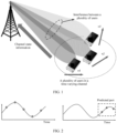
- a channel is described by using a time domain (time domain), a frequency domain (frequency domain), and a spatial domain (spatial domain), and corresponding physical channel modeling parameters are parameters such as an angle, a multipath delay, and Doppler of the channel.
- Each line parallel to spatial coordinates in the figure is a vector. For example, if UE includes one receive antenna, and a base station includes 32 antennas, that is, 32 antenna ports, a length of each vector is 32. A total quantity of vectors is Nsb multiplied by Nslot.
- the channel may be described by using an angle, a multipath delay, and a weighting coefficient, and is shown in the following formula 2:
- g p is a weighting coefficient of a p th path, may be a complex number or may be a real number, and may be understood as a relative signal strength and a relative phase of the path.
- a previous column vector is a delay vector, and a delay parameter corresponding to the delay vector is ⁇ p .
- a delay is a time difference between sending a signal and receiving the signal.
- a next row vector is an angle vector, and an angle parameter corresponding to the angle vector is ⁇ p .
- An angle is an included angle between a transmission path and an antenna array panel.
- M is a quantity of antennas in an antenna array
- d is a physical distance between two adjacent antennas
- p is a sequence number of a transmission path, and ranges from 1 to P.
- f l to f k are frequencies corresponding to subbands on the channel.
- ⁇ is a signal wavelength corresponding to a center carrier of the channel.
- the channel is described by using Doppler.
- Embodiments of this application provide a method for predicting channel state information and a communication apparatus, to predict a channel in a movement scenario with reference to an AR model and a physical channel modeling technology.
- all parameters of a channel are allowed to change.
- a network device receives channel prediction information sent by user equipment, and predicts channel information based on the channel prediction information, so that the channel information can be accurately obtained in a timely manner. This resolves an expiration problem of the channel information and improves communication reliability.
- FIG. 4 is a schematic diagram of an architecture of a communication system to which an embodiment of this application is applicable.
- the communication system may include at least one network device 100 (where only one is shown) and one or more user equipments 200 connected to the network device 100.
- the network device 100 may be a device that can communicate with user equipment.
- the network device 100 may be any device having a wireless transceiver function, and includes but is not limited to a NodeB (NodeB), an evolved NodeB (eNodeB), a base station in a fifth generation (fifth generation, 5G) communication system, a base station in a future communication system, an access node in a Wi-Fi system, a wireless relay node, a wireless backhaul node, and the like.
- the base station may be a radio controller in a cloud radio access network (cloud radio access network, CRAN) scenario.
- cloud radio access network cloud radio access network, CRAN
- the base station may be a small cell, a transmission reception point (transmission reception point, TRP), a gNB, a 6G-oriented NodeB, or the like.
- TRP transmission reception point
- gNB transmission reception point
- 6G-oriented NodeB 6G-oriented NodeB
- User equipment in this application is a device having a wireless transceiver function, and may be deployed on land, including an indoor device, an outdoor device, a handheld device, a wearable device, or a vehicle-mounted device; may be deployed on water, for example, on a ship; or may be deployed in the air, for example, on a plane, a balloon, or a satellite.
- a terminal may be a mobile phone (mobile phone), a tablet computer (pad), a computer having a wireless transceiver function, virtual reality (virtual reality, VR) user equipment, augmented reality (augmented reality, AR) user equipment, a wireless terminal in industrial control (industrial control), a wireless terminal in self-driving (self-driving), a wireless terminal in remote medical (remote medical), a wireless terminal in a smart grid (smart grid), a wireless terminal in transportation safety (transportation safety), a wireless terminal in a smart city (smart city), a wireless terminal in a smart home (smart home), a wearable device, a vehicle-mounted device, or the like.
- An application scenario is not limited in embodiments of this application.
- the user equipment may also be referred to as access user equipment, a UE unit, a mobile station, a remote station, remote user equipment, a mobile device, a wireless communication device, a UE agent, a UE apparatus, or the like.
- a plurality of means two or more. In view of this, “a plurality of” may also be understood as “at least two” in embodiments of this application.
- the term “and/or” describes an association relationship between associated objects and represents that three relationships may exist. For example, A and/or B may represent the following three cases: Only A exists, both A and B exist, and only B exists. In addition, the character “/" generally indicates an “or” relationship between the associated objects unless otherwise specified.
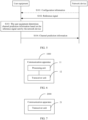
- FIG. 5 is a schematic flowchart of a method for predicting channel state information according to an embodiment of this application. The method may include the following steps.
- S101 A network device sends configuration information to user equipment.
- the user equipment receives the configuration information.
- the network device may send radio resource control (radio resource control, RRC) signaling, a media access control-control element (media access control-control element, MAC-CE), or the like to the user equipment, and include the configuration information in the RRC signaling or the MAC-CE.
- the configuration information may be carried in a reserved field or a user-defined field of the RRC signaling, the MAC-CE, or the like.
- the configuration information is used to configure channel prediction information that the UE needs to feed back.
- the channel prediction information may specifically include an angle parameter, a delay parameter, a quantity of weighting coefficients, angle prediction information, delay prediction information, weighting coefficient prediction information, a prediction order, and the like.
- the UE receives the RRC signaling, the MAC-CE, or the like, and obtains the configuration information carried in the RRC signaling, the MAC-CE, or the like.
- S102 The network device sends a reference signal to the user equipment.
- the user equipment receives the reference signal.
- the reference signal may also be referred to as a pilot.
- the network device may send reference signals at N moments.
- N is an integer greater than or equal to 1.
- the N moments may be continuous or discontinuous.
- the network device first sends information about a time-frequency resource location of the reference signal to the UE, and the UE accurately receives, at the time-frequency resource location, the reference signal sent by the network device.
- the user equipment determines channel prediction information based on the reference signal sent by the network device, where the channel prediction information is used to predict channel information.
- the UE measures the reference signal sent by the network device, to obtain channel parameters at the N moments.
- the channel parameters include an angle parameter, a delay parameter, a weighting coefficient, and the like.
- the UE determines channel prediction information corresponding to channel parameters by using the channel parameters at the N moments or channel parameters at M moments of the N moments, where M ⁇ N.
- the channel prediction information may be used to predict future channel information, so that the network device can predict each channel parameter based on the channel prediction information. Accuracy of a predicted channel parameter is high, and a delay problem of channel information is resolved.
- the channel prediction information includes the angle prediction information, the delay prediction information, or angle-delay pair prediction information, and may further include the weighting coefficient prediction information.
- the channel information is constructed based on a group of angle vectors and a group of delay vectors.
- Each angle vector is constructed based on an angle parameter corresponding to the angle vector, and each delay vector is constructed based on a delay parameter corresponding to the delay vector.
- the channel prediction information includes the angle prediction information and the delay prediction information. The angle prediction information is used to predict the angle parameter, and the delay prediction information is used to predict the delay parameter.
- the angle parameter and the delay parameter are changeable.
- the user equipment determines angle prediction information of an angle AR model based on a relationship that is between angle parameters at a plurality of moments and that is obtained through measurement, and determines delay prediction information of a delay AR model based on a relationship that is between delay parameters at a plurality of moments and that is obtained through measurement.
- the determined angle prediction information is not correlated with the determined delay prediction information.
- the user equipment may separately feed back the angle prediction information and the delay prediction information by using two pieces of signaling.
- the network device may separately obtain the angle prediction information and the delay prediction information, to separately predict an angle parameter at a future moment based on the angle prediction information and predict a delay parameter at a future moment based on the delay prediction information.
- ⁇ l 1 ( n - j ) is an angle parameter at a moment n-j
- ⁇ l 1 ( j ) is the angle prediction information
- p1 is an order of the angle AR model
- p1 may be less than or equal to N.
- p1 may be 3.
- the network device may obtain an angle parameter at a future moment in a timely manner, to resolve a channel information expiration problem.
- the angle parameters at the p1 moments are changeable, that is, the predicted angle parameter is applicable to a scenario in which the user equipment moves.
- ⁇ l 2 ( n - j ) is a delay parameter at the moment n-j
- ⁇ l 2 ( j ) is the delay prediction information
- p2 is an order of the delay AR model
- p2 may be less than or equal to N.
- p2 may be 3.
- the network device may obtain a delay parameter at a future moment in a timely manner, to resolve a channel information expiration problem.
- the delay parameters at the p2 moments are changeable, that is, the predicted delay parameter is applicable to a scenario in which the user equipment moves.
- p2 may be the same as or different from p1.
- the channel information is constructed based on a weighted sum of a group of angle-delay pairs, each angle-delay pair corresponds to a weighting coefficient and is constructed based on an angle vector in the group of angle vectors and a delay vector in the group of delay vectors, and the channel prediction information further includes weighting coefficient prediction information used to predict the weighting coefficient.
- the weighting coefficient may be predicted by using an AR model, or the user equipment may send N weighting coefficients to the network device.
- the weighting coefficient prediction information may be determined based on angle-delay pairs at a plurality of moments.
- the weighting coefficient may be a complex number, or may be a real number.
- the channel information is constructed based on a group of angle-delay pairs, each angle-delay pair is constructed based on an angle vector and a delay vector, each angle vector is constructed based on an angle parameter corresponding to the angle vector, each delay vector is constructed based on a delay parameter corresponding to the delay vector, the channel prediction information includes angle-delay pair prediction information used to predict an angle-delay parameter corresponding to the angle-delay pair, and the angle-delay parameter includes the angle parameter and the delay parameter.
- the user equipment constructs an angle-delay pair based on an angle vector and a delay vector, to obtain a group of constructed angle-delay pairs.
- the user equipment may determine the angle-delay pair prediction information of the AR model based on angle-delay parameters at a plurality of moments obtained through measurement.
- the user equipment may feed back the angle-delay pair prediction information by using a piece of signaling.
- the network device may obtain a predicted angle parameter and a predicted delay parameter based on angle-delay parameters.
- the angle parameter and the delay parameter correspond to a piece of angle-delay pair prediction information.
- the angle parameter and the delay parameter may be independent parameters or correlated parameters.
- the angle parameter and the delay parameter may be independent parameters.
- ⁇ l3 ( n ) is an angle parameter at the moment n
- ⁇ l 3 ( n ) is a delay parameter at the moment n
- ⁇ l 3 n ⁇ j is an angle-delay parameter at the moment n-j
- ⁇ l 3 ( n - j ) is an angle parameter at the moment n-j
- ⁇ l 3 ( n - j ) is a delay parameter at the moment n-j
- ⁇ l 3 ( j ) is the angle-delay pair prediction information
- p3 is an order of an angle-delay AR model
- p3 ⁇ 1, and p3 may be less than or equal to N.
- p3 may be 3.
- the user equipment may feed back the angle-delay pair prediction information by using a piece of signaling.
- the network device may obtain an angle-delay parameter at a future moment in a timely manner, to resolve a channel information expiration problem.
- the angle parameters and the delay parameters at the p3 moments are changeable, that is, the predicted angle parameter and the predicted delay parameter is applicable to a scenario in which the user equipment moves.
- the angle parameter and the delay parameter may be correlated parameters.
- ⁇ l 4 ( n ) is an angle parameter at the moment n
- ⁇ l 4 ( n ) is a delay parameter at the moment n
- ⁇ l 4 n ⁇ j ⁇ l 4 n ⁇ j is an angle-delay parameter at the moment n-j
- ⁇ l 4 ( n - j ) is an angle parameter at the moment n-j
- ⁇ l 4 ( n - j ) is a delay parameter at the moment n-j
- ⁇ l 4,1 j ⁇ l 4,2 j ⁇ l 4,3 j ⁇ l 4,4 j is the angle-delay pair prediction information
- p4 is an order of an angle-delay AR model
- p4 ⁇ 1, and p4 may be less than or equal to N.
- p4 may be 3.
- the angle-delay pair prediction information may be fed back by using a piece of signaling.
- the network device may obtain an angle-delay parameter at a future moment in a timely manner, to resolve a channel information expiration problem.
- the angle parameters and the delay parameters at the p4 moments are changeable, that is, the predicted angle parameter and the predicted delay parameter is applicable to a scenario in which the user equipment moves.
- the channel information is constructed based on a weighted sum of the group of angle-delay pairs, each angle-delay pair corresponds to a weighting coefficient, and the channel prediction information further includes weighting coefficient prediction information used to predict the weighting coefficient.
- the weighting coefficient is used to perform linear weighting on angle information and delay information.
- the weighting coefficient may be predicted by using the AR model, or the user equipment may send N weighting coefficients to the network device.
- the weighting coefficient prediction information may be determined based on angle-delay pairs at a plurality of moments.
- the weighting coefficient may be a complex number, or may be a real number.
- each piece of prediction information is predicted based on an autoregressive algorithm.
- an AR model is a method for processing time series and is used to predict a current value x t based on historical values of a variable such as x, that is, x 1 to x t-1 . It is assumed that the current value of the variable is obtained through linear transformation of the historical values.
- a channel change rule may also be modeled by using the AR model, that is, current channel information may be accurately predicted based on historical channel information by using the AR model.
- S104 The user equipment sends the channel prediction information to the network device.
- the network device receives the channel prediction information.
- the network device may further receive channel information at a plurality of moments, and may predict channel information at a future moment based on the channel prediction information and the channel information at the plurality of moments.
- the user equipment sends the channel prediction information to the network device, and the network device can accurately predict the channel information in a timely manner based on the channel prediction information. This resolves an expiration problem of the channel information fed back by the user equipment, and is applicable to the scenario in which the user equipment moves.
- FIG. 6 is a schematic structural diagram of a communication apparatus 1000 according to an embodiment of this application.
- the communication apparatus 1000 includes a processing unit 11 and a transceiver unit 12.
- the processing unit 11 is configured to determine channel prediction information based on a reference signal sent by a network device, where the channel prediction information is used to predict channel information; and the transceiver unit 12 is configured to send the channel prediction information.
- processing unit 11 and the transceiver unit 12 For specific implementation of the processing unit 11 and the transceiver unit 12, refer to the descriptions of the user equipment in the embodiment shown in FIG. 5 . Details are not described herein again.
- the user equipment sends the channel prediction information to the network device, and the network device can accurately predict the channel information in a timely manner based on the channel prediction information. This resolves an expiration problem of the channel information fed back by the user equipment, and is applicable to a scenario in which the user equipment moves.
- an embodiment of this application further provides a communication apparatus.
- the communication apparatus may be the network device in the embodiment shown in FIG. 5.
- FIG. 7 is a schematic structural diagram of another communication apparatus according to an embodiment of this application.
- the communication apparatus 2000 includes a transceiver unit 21.
- the transceiver unit 21 is configured to send a reference signal.
- the transceiver unit 21 is further configured to receive channel prediction information determined by user equipment based on the reference signal, where the channel prediction information is used to predict channel information.
- transceiver unit 21 For specific implementation of the transceiver unit 21, refer to the descriptions of the network device in the embodiment shown in FIG. 5 . Details are not described herein again.
- the network device receives the channel prediction information sent by the user equipment, and the network device can accurately predict the channel information in a timely manner based on the channel prediction information. This resolves an expiration problem of the channel information fed back by the user equipment, and is applicable to a scenario in which the user equipment moves.
- An embodiment of this application further provides a communication apparatus.
- the communication apparatus is configured to perform the foregoing method for predicting channel state information.
- a part or all of the foregoing method for predicting channel state information may be implemented by hardware, or may be implemented by software.
- the communication apparatus may be a chip or an integrated circuit.
- the communication apparatus when a part or all of the method for predicting channel state information in the foregoing embodiment is implemented by software, the communication apparatus includes a processor that is configured to execute a program. When the program is executed, the communication apparatus is enabled to implement the method for predicting channel state information provided in the foregoing embodiment.
- the communication apparatus may further include a memory that is configured to store necessary programs. These related programs may be loaded into the memory at delivery of the communication apparatus, or may be loaded into the memory when needed later.
- the memory may be a physically independent unit, or may be integrated with the processor.
- the communication apparatus may alternatively include only a processor.
- a memory configured to store a program is located outside the communication apparatus.
- the processor is connected to the memory by using a circuit/wire, and is configured to read and execute the program stored in the memory.
- the processor may be a central processing unit (central processing unit, CPU), a network processor (network processor, NP), or a combination of the CPU and the NP.
- CPU central processing unit
- NP network processor
- the processor may include a hardware chip.
- the hardware chip may be an application-specific integrated circuit (application-specific integrated circuit, ASIC), a programmable logic device (programmable logic device, PLD), or a combination thereof.
- the PLD may be a complex programmable logic device (complex programmable logic device, CPLD), a field-programmable gate array (field-programmable gate array, FPGA), a generic array logic (generic array logic, GAL), or any combination thereof.
- the memory may include a volatile memory (volatile memory), for example, a random access memory (random access memory, RAM).
- volatile memory volatile memory
- RAM random access memory
- non-volatile memory non-volatile memory
- flash memory flash memory
- hard disk drive hard disk drive
- solid-state drive solid-state drive
- SSD solid-state drive
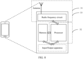
- FIG. 8 is a simplified schematic structural diagram of user equipment.
- the user equipment includes a processor, and may further include a radio frequency circuit, an antenna, and an input/output apparatus.
- the processor may be configured to process a communication protocol and communication data, and may be further configured to control the user equipment, execute a software program, process data of the software program, and the like.
- the user equipment may further include a memory.
- the memory is mainly configured to store the software program and the data. These related programs may be loaded into the memory at delivery of the communication apparatus, or may be loaded into the memory when needed later.
- the radio frequency circuit is mainly configured to: perform conversion between a baseband signal and a radio frequency signal, and process the radio frequency signal.
- the antenna is mainly configured to receive and send a radio frequency signal in a form of an electromagnetic wave.
- the input/output apparatus such as a touchscreen, a display, or a keyboard, is mainly configured to: receive data input by a user and output data to the user. It should be noted that some types of user equipment may not have an input/output apparatus.
- the processor When data needs to be sent, after performing baseband processing on the to-be-sent data, the processor outputs a baseband signal to the radio frequency circuit; and the radio frequency circuit performs radio frequency processing on the baseband signal and then sends a radio frequency signal to the outside in a form of an electromagnetic wave through the antenna.
- the radio frequency circuit receives a radio frequency signal through the antenna, converts the radio frequency signal into a baseband signal, and outputs the baseband signal to the processor, and the processor converts the baseband signal into data and processes the data.
- FIG. 8 shows only one memory and one processor. In an actual user equipment product, there may be one or more processors and one or more memories.
- the memory may also be referred to as a storage medium, a storage device, or the like.
- the memory may be disposed independent of the processor, or may be integrated with the processor. This is not limited in this embodiment of this application.
- the antenna and the radio frequency circuit that have transceiver functions may be considered as a receiving unit and a sending unit (which may also be collectively referred to as a transceiver unit) of the user equipment, and the processor having a processing function may be considered as a processing unit of the user equipment.
- the user equipment includes a receiving unit 31, a processing unit 32, and a sending unit 33.
- the receiving unit 31 may also be referred to as a receiver, a receiver machine, a receiver circuit, or the like.
- the sending unit 33 may also be referred to as a sender, a transmitter, a transmitter machine, a transmitter circuit, or the like.
- the processing unit may also be referred to as a processor, a processing board, a processing module, a processing apparatus, or the like.
- the receiving unit 31 is configured to perform steps S101 and 5102 in the embodiment shown in FIG. 5
- the processing unit 32 is configured to perform step S103 in the embodiment shown in FIG. 5
- the sending unit 33 is configured to perform step S 104 in the embodiment shown in FIG. 5 .
- FIG. 9 is a simplified schematic structural diagram of a network device.
- the network device includes a part 42 and a part for radio frequency signal transmission/reception and conversion.
- the part for radio frequency signal transmission/reception and conversion further includes a receiving unit part 41 and a sending unit part 43 (which may also be collectively referred to as a transceiver unit).
- the part for radio frequency signal transmission/reception and conversion is mainly configured to: send/receive a radio frequency signal and perform conversion between a radio frequency signal and a baseband signal.
- the part 42 is mainly configured to: perform baseband processing, control the network device, and the like.
- the receiving unit 41 may also be referred to as a receiver, a receiver machine, a receiver circuit, or the like.
- the sending unit 43 may also be referred to as a sender, a transmitter, a transmitter machine, a transmitter circuit, or the like.
- the part 42 is usually a control center of the network device, may usually be referred to as a processing unit, and is configured to control the network device to perform steps performed by the network device in FIG. 5 .
- a control center of the network device may usually be referred to as a processing unit, and is configured to control the network device to perform steps performed by the network device in FIG. 5 .
- the part 42 may include one or more boards. Each board may include one or more processors and one or more memories.
- the processor is configured to read and execute a program in the memory to implement a baseband processing function and control the network device. If there are a plurality of boards, the boards may be interconnected to improve a processing capability.
- a plurality of boards may share one or more processors, a plurality of boards may share one or more memories, or a plurality of boards may simultaneously share one or more processors.
- the sending unit 43 is configured to perform steps S101 and 5102 in the embodiment shown in FIG. 5 .
- the receiving unit 41 is configured to perform step S104 in the embodiment shown in FIG. 5 .
- An embodiment of this application further provides a computer-readable storage medium.
- the computer-readable storage medium stores instructions. When the instructions are run on a computer, the computer is enabled to perform the foregoing method.
- An embodiment of this application further provides a computer program product including instructions.
- the computer program product runs on a computer, the computer is enabled to perform the foregoing method.
- division into the units is merely logical function division and may be another division manner during actual implementation.
- a plurality of units or components may be combined or integrated into another system, or some features may be ignored or not performed.
- the displayed or discussed mutual couplings or direct couplings or communication connections may be implemented through some interfaces.
- the indirect couplings or communication connections between the apparatuses or units may be implemented in electrical, mechanical, or other forms.
- the units described as separate parts may or may not be physically separate, and parts displayed as units may or may not be physical units, that is, may be located in one position, or may be distributed on a plurality of network units. Some or all of the units may be selected based on actual requirements to achieve the objectives of the solutions of embodiments.
- All or a part of the foregoing embodiments may be implemented by software, hardware, firmware, or any combination thereof.
- all or a part of embodiments may be implemented in a form of a computer program product.
- the computer program product includes one or more computer instructions.
- the computer may be a general-purpose computer, a dedicated computer, a computer network, or another programmable apparatus.
- the computer instructions may be stored in a computer-readable storage medium, or transmitted by using the computer-readable storage medium.
- the computer instructions may be transmitted from a website, computer, server, or data center to another website, computer, server, or data center in a wired (for example, a coaxial cable, an optical fiber, or a digital subscriber line (digital subscriber line, DSL)) or wireless (for example, infrared, radio, or microwave) manner.
- the computer-readable storage medium may be any usable medium accessible to a computer, or a data storage device integrating one or more usable media, such as a server or a data center.
- the usable medium may be a read-only memory (read-only memory, ROM), a random access memory (random access memory, RAM), or a magnetic medium, for example, a floppy disk, a hard disk, a magnetic tape, a magnetic disk, or an optical medium, for example, a digital versatile disc (digital versatile disc, DVD), or a semiconductor medium, for example, a solid-state drive (solid state disk, SSD).
- ROM read-only memory
- RAM random access memory
- a magnetic medium for example, a floppy disk, a hard disk, a magnetic tape, a magnetic disk, or an optical medium, for example, a digital versatile disc (digital versatile disc, DVD), or a semiconductor medium, for example, a solid-state drive (solid state disk, SSD).
Landscapes
- Engineering & Computer Science (AREA)
- Computer Networks & Wireless Communication (AREA)
- Signal Processing (AREA)
- Physics & Mathematics (AREA)
- Electromagnetism (AREA)
- Power Engineering (AREA)
- Quality & Reliability (AREA)
- Artificial Intelligence (AREA)
- Evolutionary Computation (AREA)
- Mobile Radio Communication Systems (AREA)
- Management, Administration, Business Operations System, And Electronic Commerce (AREA)
Claims (11)
- Procédé de prédiction d'informations d'état de canal, comprenant :
la détermination (S103) d'informations de prédiction de canal sur la base d'un signal de référence envoyé par un dispositif réseau, dans lequel les informations de prédiction de canal sont utilisées pour prédire des informations de canal ; et caractérisé en ce qu'il comprend :l'envoi (S104) des informations de prédiction de canal,dans lequel les informations de canal sont construites sur la base d'un groupe de vecteurs d'angle et d'un groupe de vecteurs de retard, chaque vecteur d'angle est construit sur la base d'un paramètre d'angle correspondant au vecteur d'angle, chaque vecteur de retard est construit sur la base d'un paramètre de retard correspondant au vecteur de retard, les informations de prédiction de canal comprennent des informations de prédiction d'angle et des informations de prédiction de retard, les informations de prédiction d'angle sont utilisées pour prédire les paramètres d'angle, et les informations de prédiction de retard sont utilisées pour prédire les paramètres de retard,et dans lequel les informations de canal sont construites sur la base d'une somme pondérée d'un groupe de paires angle-retard, chaque paire angle-retard correspond à un coefficient de pondération et est construite sur la base d'un vecteur d'angle dans le groupe de vecteurs d'angle et d'un vecteur de retard dans le groupe de vecteurs de retard, et les informations de prédiction de canal comprennent également des informations de prédiction de coefficient de pondération utilisées pour prédire le coefficient de pondération. - Procédé de détermination d'informations d'état de canal, comprenant :
l'envoi (S102) d'un signal de référence ; et caractérisé en ce qu'il comprend également :la réception (S104) des informations de prédiction de canal déterminées par un équipement utilisateur sur la base du signal de référence,dans lequel les informations de prédiction de canal sont utilisées pour prédire les informations de canal ; etla prédiction des informations de canal sur la base des informations de prédiction de canal,dans lequel les informations de canal sont construites sur la base d'un groupe de vecteurs d'angle et d'un groupe de vecteurs de retard, chaque vecteur d'angle est construit sur la base d'un paramètre d'angle correspondant au vecteur d'angle, chaque vecteur de retard est construit sur la base d'un paramètre de retard correspondant au vecteur de retard, les informations de prédiction de canal comprennent des informations de prédiction d'angle et des informations de prédiction de retard, les informations de prédiction d'angle sont utilisées pour prédire les paramètres d'angle, et les informations de prédiction de retard sont utilisées pour prédire les paramètres de retard,et dans lequel les informations de canal sont construites sur la base d'une somme pondérée d'un groupe de paires angle-retard, chaque paire angle-retard correspond à un coefficient de pondération et est construite sur la base d'un vecteur d'angle dans le groupe de vecteurs d'angle et d'un vecteur de retard dans le groupe de vecteurs de retard, et les informations de prédiction de canal comprennent également des informations de prédiction de coefficient de pondération utilisées pour prédire le coefficient de pondération. - Procédé selon la revendication 1 ou 2, dans lequel à un instant n, un paramètre d'angle θ l1(n) correspondant à un vecteur d'angle 11 satisfait :

- Procédé selon l'une quelconque des revendications 1 à 3, dans lequel à l'instant n, un paramètre de retard τ l2(n) d'un vecteur de retard 12 satisfait :

- Procédé selon l'une quelconque des revendications 1 à 4, dans lequel chaque élément d'information de prédiction est prédit sur la base d'un algorithme autorégressif.
- Appareil de communication (1000), comprenant :une unité de traitement (11), configurée pour déterminer des informations de prédiction de canal sur la base d'un signal de référence envoyé par un dispositif réseau, dans lequel les informations de prédiction de canal sont utilisées pour prédire des informations de canal ; etcaractérisé en ce qu'il comprend également :une unité émettrice-réceptrice (12), configurée pour envoyer les informations de prédiction de canal,dans lequel les informations de canal sont construites sur la base d'un groupe de vecteurs d'angle et d'un groupe de vecteurs de retard, chaque vecteur d'angle est construit sur la base d'un paramètre d'angle correspondant au vecteur d'angle, chaque vecteur de retard est construit sur la base d'un paramètre de retard correspondant au vecteur de retard, les informations de prédiction de canal comprennent des informations de prédiction d'angle et des informations de prédiction de retard, les informations de prédiction d'angle sont utilisées pour prédire les paramètres d'angle, et les informations de prédiction de retard sont utilisées pour prédire les paramètres de retard,et dans lequel les informations de canal sont construites sur la base d'une somme pondérée d'un groupe de paires angle-retard, chaque paire angle-retard correspond à un coefficient de pondération et est construite sur la base d'un vecteur d'angle dans le groupe de vecteurs d'angle et d'un vecteur de retard dans le groupe de vecteurs de retard, et les informations de prédiction de canal comprennent également des informations de prédiction de coefficient de pondération utilisées pour prédire le coefficient de pondération.
- Appareil de communication (2000), comprenant :une unité émettrice-réceptrice (21), configurée pour envoyer un signal de référence, caractérisé en ce que l'unité émettrice-réceptrice est également configurée pour recevoir des informations de prédiction de canal déterminées par un équipement utilisateur sur la base du signal de référence, dans lequel les informations de prédiction de canal sont utilisées pour prédire des informations de canal ; eten ce que l'appareil de communication comprend également :une unité de traitement, configurée pour prédire les informations de canal sur la base des informations de prédiction de canal,dans lequel les informations de canal sont construites sur la base d'un groupe de vecteurs d'angle et d'un groupe de vecteurs de retard, chaque vecteur d'angle est construit sur la base d'un paramètre d'angle correspondant au vecteur d'angle, chaque vecteur de retard est construit sur la base d'un paramètre de retard correspondant au vecteur de retard, les informations de prédiction de canal comprennent des informations de prédiction d'angle et des informations de prédiction de retard, les informations de prédiction d'angle sont utilisées pour prédire les paramètres d'angle, et les informations de prédiction de retard sont utilisées pour prédire les paramètres de retard,et dans lequel les informations de canal sont construites sur la base d'une somme pondérée d'un groupe de paires angle-retard, chaque paire angle-retard correspond à un coefficient de pondération et est construite sur la base d'un vecteur d'angle dans le groupe de vecteurs d'angle et d'un vecteur de retard dans le groupe de vecteurs de retard, et les informations de prédiction de canal comprennent également des informations de prédiction de coefficient de pondération utilisées pour prédire le coefficient de pondération.
- Appareil (1000, 2000) selon la revendication 6 ou 7, dans lequel à un instant n, un paramètre d'angle θ l1(n) correspondant à un vecteur d'angle 11 satisfait :

- Appareil (1000, 2000) selon l'une quelconque des revendications 6 à 8, dans lequel à l'instant n, un paramètre de retard τ l2(n) d'un vecteur de retard 12 satisfait :

- Appareil (1000, 2000) selon l'une quelconque des revendications 6 à 9, dans lequel chaque élément d'information de prédiction est prédit sur la base d'un algorithme autorégressif.
- Support de stockage lisible par ordinateur, comprenant des instructions, dans lequel, lorsque les instructions sont exécutées sur un ordinateur dans un appareil de communication, l'appareil de communication réalise le procédé selon l'une quelconque des revendications 1 à 5.
Applications Claiming Priority (1)
| Application Number | Priority Date | Filing Date | Title |
|---|---|---|---|
| PCT/CN2020/076282 WO2021164033A1 (fr) | 2020-02-21 | 2020-02-21 | Procédé et appareil de prédiction d'informations d'état de canal |
Publications (3)
| Publication Number | Publication Date |
|---|---|
| EP4096177A1 EP4096177A1 (fr) | 2022-11-30 |
| EP4096177A4 EP4096177A4 (fr) | 2023-01-18 |
| EP4096177B1 true EP4096177B1 (fr) | 2025-01-15 |
Family
ID=77390392
Family Applications (1)
| Application Number | Title | Priority Date | Filing Date |
|---|---|---|---|
| EP20919779.7A Active EP4096177B1 (fr) | 2020-02-21 | 2020-02-21 | Procédé et appareil de prédiction d'informations d'état de canal |
Country Status (4)
| Country | Link |
|---|---|
| US (1) | US20220407616A1 (fr) |
| EP (1) | EP4096177B1 (fr) |
| CN (1) | CN115053498B (fr) |
| WO (1) | WO2021164033A1 (fr) |
Families Citing this family (6)
| Publication number | Priority date | Publication date | Assignee | Title |
|---|---|---|---|---|
| US20240348356A1 (en) * | 2021-10-20 | 2024-10-17 | Telefonaktiebolaget Lm Ericsson (Publ) | Determination of Autoregressive Model Order for a Channel Prediction Filter |
| CN116074210B (zh) * | 2021-11-01 | 2026-03-10 | 维沃移动通信有限公司 | 信道预测方法、装置、网络侧设备及终端 |
| CN116137553B (zh) * | 2021-11-17 | 2026-03-20 | 维沃移动通信有限公司 | 一种信道预测方法、装置、ue及系统 |
| CN116963107A (zh) * | 2022-04-18 | 2023-10-27 | 北京紫光展锐通信技术有限公司 | 信道信息获取方法及装置 |
| WO2024254779A1 (fr) * | 2023-06-14 | 2024-12-19 | Qualcomm Incorporated | Indication d'occupation de domaine fréquentiel virtuelle pour une prédiction de mesure de faisceau |
| US20250150120A1 (en) * | 2023-11-02 | 2025-05-08 | Qualcomm Incorporated | Sub-slot precoding for wireless communications |
Family Cites Families (12)
| Publication number | Priority date | Publication date | Assignee | Title |
|---|---|---|---|---|
| US20090122854A1 (en) * | 2007-11-14 | 2009-05-14 | The Hong Kong University Of Science And Technology | Frequency domain equalization with transmit precoding for high speed data transmission |
| JP5149257B2 (ja) * | 2009-10-02 | 2013-02-20 | シャープ株式会社 | 無線通信システム、通信装置および無線通信方法 |
| US9219533B2 (en) * | 2011-10-25 | 2015-12-22 | Transpacific Ip Management Group Ltd. | Systems and methods for downlink scheduling in multiple input multiple output wireless communications systems |
| WO2014073846A1 (fr) * | 2012-11-07 | 2014-05-15 | 주식회사 팬택 | Procédé et appareil pour émettre et recevoir des informations de canal dans un système de communication sans fil |
| KR102011995B1 (ko) * | 2012-11-23 | 2019-08-19 | 삼성전자주식회사 | 빔포밍 기반 무선통신 시스템에서 송수신 빔 패턴 변경에 따른 빔 이득 보상 운용을 위한 방법 및 장치 |
| CN106411457B (zh) * | 2015-07-31 | 2021-07-09 | 北京三星通信技术研究有限公司 | 信道状态信息获取方法、反馈方法、基站及终端 |
| EP3738281B1 (fr) * | 2018-01-12 | 2024-01-03 | Nokia Technologies Oy | Réponse profilée à impulsion de canal servant à une estimation précise de paramètres de trajets multiples |
| CN108418770A (zh) * | 2018-01-22 | 2018-08-17 | 南京邮电大学 | 大规模mimo中基于信道估计误差的频域信道互易补偿方法 |
| CN108933745B (zh) * | 2018-07-16 | 2020-07-10 | 北京理工大学 | 一种基于超分辨率角度和时延估计的宽带信道估计方法 |
| CN110430147B (zh) * | 2019-07-15 | 2021-12-14 | 东南大学 | 一种面向fdd系统的信道跟踪方法 |
| CN110830133B (zh) * | 2019-12-23 | 2020-12-01 | 华中科技大学 | 一种基于多阶信道预测方法、预测系统及应用 |
| US11337095B2 (en) * | 2020-01-03 | 2022-05-17 | Qualcomm Incorporated | Forward-looking channel state information prediction and reporting |
-
2020
- 2020-02-21 EP EP20919779.7A patent/EP4096177B1/fr active Active
- 2020-02-21 WO PCT/CN2020/076282 patent/WO2021164033A1/fr not_active Ceased
- 2020-02-21 CN CN202080095569.4A patent/CN115053498B/zh active Active
-
2022
- 2022-08-19 US US17/891,267 patent/US20220407616A1/en active Pending
Also Published As
| Publication number | Publication date |
|---|---|
| EP4096177A1 (fr) | 2022-11-30 |
| EP4096177A4 (fr) | 2023-01-18 |
| CN115053498B (zh) | 2024-05-14 |
| WO2021164033A1 (fr) | 2021-08-26 |
| US20220407616A1 (en) | 2022-12-22 |
| CN115053498A (zh) | 2022-09-13 |
Similar Documents
| Publication | Publication Date | Title |
|---|---|---|
| EP4096177B1 (fr) | Procédé et appareil de prédiction d'informations d'état de canal | |
| US12489505B2 (en) | Improving precoding | |
| CN108696889B (zh) | 波束测量和反馈的方法及使用所述方法的基站与用户设备 | |
| US10348376B2 (en) | Wireless communication device and wireless communication method | |
| EP3780410A1 (fr) | Rapport csi et structure de livre de codes pour un précodage à base de livre de codes doppler dans un système de communication sans fil | |
| US12568001B2 (en) | Information reporting method and apparatus, first device, and second device | |
| US10374836B2 (en) | Method and apparatus for downlink channel estimation in massive MIMO | |
| US10644773B2 (en) | Feedback channel information using pre-coders in a wireless communication system | |
| EP4049376B1 (fr) | Suivi de précodage pour système mimo massif exempt de cellules | |
| CN114631267A (zh) | 针对多传输接收点/面板和无小区多输入多输出的信道状态信息开销减少 | |
| CN109831823B (zh) | 用于通信的方法、终端设备和网络设备 | |
| US12512891B2 (en) | Wireless communication device transmitting and receiving data using channel state information feedback and operating method thereof | |
| US11431388B2 (en) | Wavelet transform-based tracking for estimating an aging wireless channel | |
| US20250227514A1 (en) | Communication method and related device | |
| CN113676234A (zh) | 具有长传播延迟的ntn中的增强csi反馈 | |
| WO2015199252A1 (fr) | Procédé de transmission de signal via une bande haute fréquence dans un système de communications sans fil, et appareil correspondant | |
| EP4325733A1 (fr) | Procédé de planification pour une formation de faisceau et entité de réseau | |
| CN114726421B (zh) | 信道反馈方法、信息传输方法及设备 | |
| KR20190075430A (ko) | 중계기를 사용하는 다중 안테나 다중 송수신 통신 시스템에서 송수신 신호 처리 방법 및 장치 | |
| Ozawa et al. | Interference alignment for time-varying channel with channel and weight predictions based on auto regressive model | |
| WO2023160456A1 (fr) | Procédé et appareil de rapport d'informations de canal, dispositif du côté réseau, terminal et support | |
| CN118381535A (zh) | 信息发送方法、接收方法、通信设备和存储介质 | |
| TWI655850B (zh) | 束波測量和回報的方法及使用所述方法的基站與用戶設備 | |
| EP3526908B1 (fr) | Estimation de canal de liaison montante relative | |
| Shi et al. | Joint frame structure and beamforming design for integrated localization and communication network |
Legal Events
| Date | Code | Title | Description |
|---|---|---|---|
| STAA | Information on the status of an ep patent application or granted ep patent |
Free format text: STATUS: THE INTERNATIONAL PUBLICATION HAS BEEN MADE |
|
| PUAI | Public reference made under article 153(3) epc to a published international application that has entered the european phase |
Free format text: ORIGINAL CODE: 0009012 |
|
| STAA | Information on the status of an ep patent application or granted ep patent |
Free format text: STATUS: REQUEST FOR EXAMINATION WAS MADE |
|
| 17P | Request for examination filed |
Effective date: 20220825 |
|
| AK | Designated contracting states |
Kind code of ref document: A1 Designated state(s): AL AT BE BG CH CY CZ DE DK EE ES FI FR GB GR HR HU IE IS IT LI LT LU LV MC MK MT NL NO PL PT RO RS SE SI SK SM TR |
|
| REG | Reference to a national code |
Ref country code: DE Ref legal event code: R079 Free format text: PREVIOUS MAIN CLASS: H04L0025200000 Ipc: H04L0025020000 Ref country code: DE Ref legal event code: R079 Ref document number: 602020045002 Country of ref document: DE Free format text: PREVIOUS MAIN CLASS: H04L0025200000 Ipc: H04L0025020000 |
|
| A4 | Supplementary search report drawn up and despatched |
Effective date: 20221216 |
|
| RIC1 | Information provided on ipc code assigned before grant |
Ipc: H04B 7/0413 20170101ALI20221212BHEP Ipc: H04B 17/373 20150101ALI20221212BHEP Ipc: H04L 25/02 20060101AFI20221212BHEP |
|
| DAV | Request for validation of the european patent (deleted) | ||
| DAX | Request for extension of the european patent (deleted) | ||
| GRAP | Despatch of communication of intention to grant a patent |
Free format text: ORIGINAL CODE: EPIDOSNIGR1 |
|
| STAA | Information on the status of an ep patent application or granted ep patent |
Free format text: STATUS: GRANT OF PATENT IS INTENDED |
|
| INTG | Intention to grant announced |
Effective date: 20240823 |
|
| GRAS | Grant fee paid |
Free format text: ORIGINAL CODE: EPIDOSNIGR3 |
|
| GRAA | (expected) grant |
Free format text: ORIGINAL CODE: 0009210 |
|
| STAA | Information on the status of an ep patent application or granted ep patent |
Free format text: STATUS: THE PATENT HAS BEEN GRANTED |
|
| AK | Designated contracting states |
Kind code of ref document: B1 Designated state(s): AL AT BE BG CH CY CZ DE DK EE ES FI FR GB GR HR HU IE IS IT LI LT LU LV MC MK MT NL NO PL PT RO RS SE SI SK SM TR |
|
| REG | Reference to a national code |
Ref country code: CH Ref legal event code: EP Ref country code: GB Ref legal event code: FG4D |
|
| REG | Reference to a national code |
Ref country code: DE Ref legal event code: R096 Ref document number: 602020045002 Country of ref document: DE |
|
| REG | Reference to a national code |
Ref country code: IE Ref legal event code: FG4D |
|
| REG | Reference to a national code |
Ref country code: NL Ref legal event code: MP Effective date: 20250115 |
|
| PG25 | Lapsed in a contracting state [announced via postgrant information from national office to epo] |
Ref country code: NL Free format text: LAPSE BECAUSE OF FAILURE TO SUBMIT A TRANSLATION OF THE DESCRIPTION OR TO PAY THE FEE WITHIN THE PRESCRIBED TIME-LIMIT Effective date: 20250115 |
|
| PG25 | Lapsed in a contracting state [announced via postgrant information from national office to epo] |
Ref country code: RS Free format text: LAPSE BECAUSE OF FAILURE TO SUBMIT A TRANSLATION OF THE DESCRIPTION OR TO PAY THE FEE WITHIN THE PRESCRIBED TIME-LIMIT Effective date: 20250415 |
|
| PG25 | Lapsed in a contracting state [announced via postgrant information from national office to epo] |
Ref country code: FI Free format text: LAPSE BECAUSE OF FAILURE TO SUBMIT A TRANSLATION OF THE DESCRIPTION OR TO PAY THE FEE WITHIN THE PRESCRIBED TIME-LIMIT Effective date: 20250115 |
|
| PG25 | Lapsed in a contracting state [announced via postgrant information from national office to epo] |
Ref country code: PL Free format text: LAPSE BECAUSE OF FAILURE TO SUBMIT A TRANSLATION OF THE DESCRIPTION OR TO PAY THE FEE WITHIN THE PRESCRIBED TIME-LIMIT Effective date: 20250115 |
|
| PG25 | Lapsed in a contracting state [announced via postgrant information from national office to epo] |
Ref country code: ES Free format text: LAPSE BECAUSE OF FAILURE TO SUBMIT A TRANSLATION OF THE DESCRIPTION OR TO PAY THE FEE WITHIN THE PRESCRIBED TIME-LIMIT Effective date: 20250115 |
|
| REG | Reference to a national code |
Ref country code: LT Ref legal event code: MG9D |
|
| PG25 | Lapsed in a contracting state [announced via postgrant information from national office to epo] |
Ref country code: IS Free format text: LAPSE BECAUSE OF FAILURE TO SUBMIT A TRANSLATION OF THE DESCRIPTION OR TO PAY THE FEE WITHIN THE PRESCRIBED TIME-LIMIT Effective date: 20250515 Ref country code: NO Free format text: LAPSE BECAUSE OF FAILURE TO SUBMIT A TRANSLATION OF THE DESCRIPTION OR TO PAY THE FEE WITHIN THE PRESCRIBED TIME-LIMIT Effective date: 20250415 |
|
| REG | Reference to a national code |
Ref country code: AT Ref legal event code: MK05 Ref document number: 1760544 Country of ref document: AT Kind code of ref document: T Effective date: 20250115 |
|
| PG25 | Lapsed in a contracting state [announced via postgrant information from national office to epo] |
Ref country code: HR Free format text: LAPSE BECAUSE OF FAILURE TO SUBMIT A TRANSLATION OF THE DESCRIPTION OR TO PAY THE FEE WITHIN THE PRESCRIBED TIME-LIMIT Effective date: 20250115 |
|
| PG25 | Lapsed in a contracting state [announced via postgrant information from national office to epo] |
Ref country code: PT Free format text: LAPSE BECAUSE OF FAILURE TO SUBMIT A TRANSLATION OF THE DESCRIPTION OR TO PAY THE FEE WITHIN THE PRESCRIBED TIME-LIMIT Effective date: 20250515 Ref country code: LV Free format text: LAPSE BECAUSE OF FAILURE TO SUBMIT A TRANSLATION OF THE DESCRIPTION OR TO PAY THE FEE WITHIN THE PRESCRIBED TIME-LIMIT Effective date: 20250115 |
|
| PG25 | Lapsed in a contracting state [announced via postgrant information from national office to epo] |
Ref country code: GR Free format text: LAPSE BECAUSE OF FAILURE TO SUBMIT A TRANSLATION OF THE DESCRIPTION OR TO PAY THE FEE WITHIN THE PRESCRIBED TIME-LIMIT Effective date: 20250416 Ref country code: BG Free format text: LAPSE BECAUSE OF FAILURE TO SUBMIT A TRANSLATION OF THE DESCRIPTION OR TO PAY THE FEE WITHIN THE PRESCRIBED TIME-LIMIT Effective date: 20250115 |
|
| PG25 | Lapsed in a contracting state [announced via postgrant information from national office to epo] |
Ref country code: AT Free format text: LAPSE BECAUSE OF FAILURE TO SUBMIT A TRANSLATION OF THE DESCRIPTION OR TO PAY THE FEE WITHIN THE PRESCRIBED TIME-LIMIT Effective date: 20250115 |
|
| PG25 | Lapsed in a contracting state [announced via postgrant information from national office to epo] |
Ref country code: SE Free format text: LAPSE BECAUSE OF FAILURE TO SUBMIT A TRANSLATION OF THE DESCRIPTION OR TO PAY THE FEE WITHIN THE PRESCRIBED TIME-LIMIT Effective date: 20250115 |
|
| REG | Reference to a national code |
Ref country code: CH Ref legal event code: PL |
|
| PG25 | Lapsed in a contracting state [announced via postgrant information from national office to epo] |
Ref country code: SM Free format text: LAPSE BECAUSE OF FAILURE TO SUBMIT A TRANSLATION OF THE DESCRIPTION OR TO PAY THE FEE WITHIN THE PRESCRIBED TIME-LIMIT Effective date: 20250115 |
|
| PG25 | Lapsed in a contracting state [announced via postgrant information from national office to epo] |
Ref country code: DK Free format text: LAPSE BECAUSE OF FAILURE TO SUBMIT A TRANSLATION OF THE DESCRIPTION OR TO PAY THE FEE WITHIN THE PRESCRIBED TIME-LIMIT Effective date: 20250115 |
|
| PG25 | Lapsed in a contracting state [announced via postgrant information from national office to epo] |
Ref country code: MC Free format text: LAPSE BECAUSE OF FAILURE TO SUBMIT A TRANSLATION OF THE DESCRIPTION OR TO PAY THE FEE WITHIN THE PRESCRIBED TIME-LIMIT Effective date: 20250115 |
|
| PG25 | Lapsed in a contracting state [announced via postgrant information from national office to epo] |
Ref country code: LU Free format text: LAPSE BECAUSE OF NON-PAYMENT OF DUE FEES Effective date: 20250221 Ref country code: IT Free format text: LAPSE BECAUSE OF FAILURE TO SUBMIT A TRANSLATION OF THE DESCRIPTION OR TO PAY THE FEE WITHIN THE PRESCRIBED TIME-LIMIT Effective date: 20250115 |
|
| REG | Reference to a national code |
Ref country code: DE Ref legal event code: R097 Ref document number: 602020045002 Country of ref document: DE |
|
| PG25 | Lapsed in a contracting state [announced via postgrant information from national office to epo] |
Ref country code: CH Free format text: LAPSE BECAUSE OF NON-PAYMENT OF DUE FEES Effective date: 20250228 |
|
| PG25 | Lapsed in a contracting state [announced via postgrant information from national office to epo] |
Ref country code: EE Free format text: LAPSE BECAUSE OF FAILURE TO SUBMIT A TRANSLATION OF THE DESCRIPTION OR TO PAY THE FEE WITHIN THE PRESCRIBED TIME-LIMIT Effective date: 20250115 Ref country code: CZ Free format text: LAPSE BECAUSE OF FAILURE TO SUBMIT A TRANSLATION OF THE DESCRIPTION OR TO PAY THE FEE WITHIN THE PRESCRIBED TIME-LIMIT Effective date: 20250115 |
|
| PG25 | Lapsed in a contracting state [announced via postgrant information from national office to epo] |
Ref country code: RO Free format text: LAPSE BECAUSE OF FAILURE TO SUBMIT A TRANSLATION OF THE DESCRIPTION OR TO PAY THE FEE WITHIN THE PRESCRIBED TIME-LIMIT Effective date: 20250115 |
|
| PG25 | Lapsed in a contracting state [announced via postgrant information from national office to epo] |
Ref country code: SK Free format text: LAPSE BECAUSE OF FAILURE TO SUBMIT A TRANSLATION OF THE DESCRIPTION OR TO PAY THE FEE WITHIN THE PRESCRIBED TIME-LIMIT Effective date: 20250115 |
|
| PLBE | No opposition filed within time limit |
Free format text: ORIGINAL CODE: 0009261 |
|
| STAA | Information on the status of an ep patent application or granted ep patent |
Free format text: STATUS: NO OPPOSITION FILED WITHIN TIME LIMIT |
|
| REG | Reference to a national code |
Ref country code: BE Ref legal event code: MM Effective date: 20250228 |
|
| 26N | No opposition filed |
Effective date: 20251016 |
|
| PG25 | Lapsed in a contracting state [announced via postgrant information from national office to epo] |
Ref country code: FR Free format text: LAPSE BECAUSE OF NON-PAYMENT OF DUE FEES Effective date: 20250315 |
|
| PG25 | Lapsed in a contracting state [announced via postgrant information from national office to epo] |
Ref country code: BE Free format text: LAPSE BECAUSE OF NON-PAYMENT OF DUE FEES Effective date: 20250228 |
|
| PG25 | Lapsed in a contracting state [announced via postgrant information from national office to epo] |
Ref country code: IE Free format text: LAPSE BECAUSE OF NON-PAYMENT OF DUE FEES Effective date: 20250221 |
|
| PGFP | Annual fee paid to national office [announced via postgrant information from national office to epo] |
Ref country code: GB Payment date: 20260106 Year of fee payment: 7 |
|
| PGFP | Annual fee paid to national office [announced via postgrant information from national office to epo] |
Ref country code: DE Payment date: 20251230 Year of fee payment: 7 |