EP4096324A1 - Verfahren zur sendeleistungskonfiguration, iab-knoten, basisstation und speichermedium - Google Patents
Verfahren zur sendeleistungskonfiguration, iab-knoten, basisstation und speichermedium Download PDFInfo
- Publication number
- EP4096324A1 EP4096324A1 EP21744404.1A EP21744404A EP4096324A1 EP 4096324 A1 EP4096324 A1 EP 4096324A1 EP 21744404 A EP21744404 A EP 21744404A EP 4096324 A1 EP4096324 A1 EP 4096324A1
- Authority
- EP
- European Patent Office
- Prior art keywords
- transmit power
- unit
- information
- iab node
- power
- Prior art date
- Legal status (The legal status is an assumption and is not a legal conclusion. Google has not performed a legal analysis and makes no representation as to the accuracy of the status listed.)
- Granted
Links
Images

Classifications
-
- H—ELECTRICITY
- H04—ELECTRIC COMMUNICATION TECHNIQUE
- H04W—WIRELESS COMMUNICATION NETWORKS
- H04W72/00—Local resource management
- H04W72/04—Wireless resource allocation
- H04W72/044—Wireless resource allocation based on the type of the allocated resource
- H04W72/0473—Wireless resource allocation based on the type of the allocated resource the resource being transmission power
-
- H—ELECTRICITY
- H04—ELECTRIC COMMUNICATION TECHNIQUE
- H04W—WIRELESS COMMUNICATION NETWORKS
- H04W52/00—Power management, e.g. Transmission Power Control [TPC] or power classes
- H04W52/04—Transmission power control [TPC]
- H04W52/30—Transmission power control [TPC] using constraints in the total amount of available transmission power
- H04W52/36—Transmission power control [TPC] using constraints in the total amount of available transmission power with a discrete range or set of values, e.g. step size, ramping or offsets
- H04W52/367—Power values between minimum and maximum limits, e.g. dynamic range
-
- H—ELECTRICITY
- H04—ELECTRIC COMMUNICATION TECHNIQUE
- H04W—WIRELESS COMMUNICATION NETWORKS
- H04W52/00—Power management, e.g. Transmission Power Control [TPC] or power classes
- H04W52/04—Transmission power control [TPC]
- H04W52/18—TPC being performed according to specific parameters
- H04W52/24—TPC being performed according to specific parameters using SIR [Signal to Interference Ratio] or other wireless path parameters
- H04W52/242—TPC being performed according to specific parameters using SIR [Signal to Interference Ratio] or other wireless path parameters taking into account path loss
-
- H—ELECTRICITY
- H04—ELECTRIC COMMUNICATION TECHNIQUE
- H04W—WIRELESS COMMUNICATION NETWORKS
- H04W52/00—Power management, e.g. Transmission Power Control [TPC] or power classes
- H04W52/04—Transmission power control [TPC]
- H04W52/18—TPC being performed according to specific parameters
- H04W52/28—TPC being performed according to specific parameters using user profile, e.g. mobile speed, priority or network state, e.g. standby, idle or non-transmission
- H04W52/281—TPC being performed according to specific parameters using user profile, e.g. mobile speed, priority or network state, e.g. standby, idle or non-transmission taking into account user or data type priority
-
- H—ELECTRICITY
- H04—ELECTRIC COMMUNICATION TECHNIQUE
- H04W—WIRELESS COMMUNICATION NETWORKS
- H04W52/00—Power management, e.g. Transmission Power Control [TPC] or power classes
- H04W52/04—Transmission power control [TPC]
- H04W52/30—Transmission power control [TPC] using constraints in the total amount of available transmission power
- H04W52/34—TPC management, i.e. sharing limited amount of power among users or channels or data types, e.g. cell loading
- H04W52/346—TPC management, i.e. sharing limited amount of power among users or channels or data types, e.g. cell loading distributing total power among users or channels
-
- H—ELECTRICITY
- H04—ELECTRIC COMMUNICATION TECHNIQUE
- H04W—WIRELESS COMMUNICATION NETWORKS
- H04W52/00—Power management, e.g. Transmission Power Control [TPC] or power classes
- H04W52/04—Transmission power control [TPC]
- H04W52/30—Transmission power control [TPC] using constraints in the total amount of available transmission power
- H04W52/36—Transmission power control [TPC] using constraints in the total amount of available transmission power with a discrete range or set of values, e.g. step size, ramping or offsets
- H04W52/365—Power headroom reporting
-
- H—ELECTRICITY
- H04—ELECTRIC COMMUNICATION TECHNIQUE
- H04W—WIRELESS COMMUNICATION NETWORKS
- H04W52/00—Power management, e.g. Transmission Power Control [TPC] or power classes
- H04W52/04—Transmission power control [TPC]
- H04W52/38—TPC being performed in particular situations
- H04W52/46—TPC being performed in particular situations in multi-hop networks, e.g. wireless relay networks
-
- H—ELECTRICITY
- H04—ELECTRIC COMMUNICATION TECHNIQUE
- H04W—WIRELESS COMMUNICATION NETWORKS
- H04W72/00—Local resource management
- H04W72/04—Wireless resource allocation
-
- H—ELECTRICITY
- H04—ELECTRIC COMMUNICATION TECHNIQUE
- H04W—WIRELESS COMMUNICATION NETWORKS
- H04W72/00—Local resource management
- H04W72/04—Wireless resource allocation
- H04W72/044—Wireless resource allocation based on the type of the allocated resource
- H04W72/0446—Resources in time domain, e.g. slots or frames
-
- H—ELECTRICITY
- H04—ELECTRIC COMMUNICATION TECHNIQUE
- H04W—WIRELESS COMMUNICATION NETWORKS
- H04W84/00—Network topologies
- H04W84/02—Hierarchically pre-organised networks, e.g. paging networks, cellular networks, WLAN [Wireless Local Area Network] or WLL [Wireless Local Loop]
- H04W84/04—Large scale networks; Deep hierarchical networks
- H04W84/042—Public Land Mobile systems, e.g. cellular systems
- H04W84/047—Public Land Mobile systems, e.g. cellular systems using dedicated repeater stations
Definitions
- Embodiments of this application relate to the communications field, and in particular, to a transmit power configuration method, an IAB node, a base station, and a storage medium.
- An integrated access and backhaul (Integrated Access Backhaul, IAB) node includes a distributed unit (Distributed Unit, DU) and a mobile termination (Mobile Termination, MT) unit. Through the MT unit, an IAB node can establish a wireless connection to a DU of a parent IAB node, so as to establish a backhaul link of the IAB node.
- DU Distributed Unit
- MT Mobile Termination
- an IAB node needs to support spatial multiplexing transmission or frequency division multiplexing transmission between a previous hop and a next hop.
- the IAB node has only one radio frequency unit, there may be a conflict between transmit powers of the DU and the MT unit, reducing communication performance of the IAB node.
- Embodiments of this application provide a transmit power configuration method, an IAB node, a base station, and a storage medium, so as to resolve the problem of low communication performance caused by a conflict between transmit powers of a DU and an MT unit of an IAB node.
- an embodiment of this application provides a transmit power configuration method, applied to an integrated access and backhaul IAB node, where the IAB node includes a distributed unit DU and a mobile termination MT unit, and the method includes:
- an embodiment of this application provides an integrated access and backhaul IAB node, where the IAB node includes a distributed unit DU and a mobile termination MT unit, and the IAB node further includes:
- an embodiment of this application provides a base station, including a processor, a memory, and a computer program stored on the memory and executable on the processor.
- the computer program is executed by the processor, the transmit power configuration method in the technical solution according to the first aspect is implemented.
- an embodiment of this application provides a computer-readable storage medium, where the computer-readable storage medium stores a computer program.
- the computer program is executed by a processor, the transmit power configuration method in the technical solution according to the first aspect is implemented.
- the IAB node determines the first transmit power configuration for the DU and/or the second transmit power configuration for the MT unit, so as to control the DU to transmit information at the transmit power indicated by the first transmit power configuration, and/or control the MT unit to transmit information at the transmit power indicated by the second transmit power configuration.
- the IAB node can configure transmit powers of the DU and the MT unit in advance, and the sum of the transmit power of the DU and the transmit power of the MT unit is less than or equal to the maximum transmit power of the IAB node, so as to implement power sharing between the DU and the MT unit of the IAB node and avoid a conflict between the transmit powers of the DU and the MT unit, thereby improving communication performance of the IAB node.
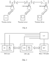
- FIG. 1 is a schematic structural diagram of an example of an IAB system according to an embodiment of this application. As shown in FIG. 1 , the IAB system includes a plurality of IAB nodes and a plurality of terminal devices. Each IAB node may access one or more terminal devices, which is not limited herein.
- An IAB node may correspond to a parent IAB node (parent IAB node), and an IAB node may correspond to a child IAB node (child IAB node).
- the second IAB node is a parent node of the first IAB node
- the third IAB node is a parent node of the second IAB node.
- An IAB node may be specifically implemented as a base station, which is not limited herein.
- a terminal device may be implemented as a mobile phone, a computer, a tablet computer, and another communications device, which is not limited herein.
- An IAB node includes a distributed unit (Distributed Unit, DU) and a mobile termination (Mobile Termination, MT) unit. Through the MT unit, an IAB node can establish a wireless connection to a DU of a parent IAB node, so as to establish a backhaul link of the IAB node.
- an integrated access and backhaul loop includes a donor IAB node (donor IAB node). The donor IAB node does not include an MT unit.
- FIG. 2 is a schematic communication diagram of an example of an IAB node and a centralized unit (Centralized Unit, CU) according to an embodiment of this application. As shown in FIG. 2 , in an integrated access and backhaul loop, DUs of all IAB nodes are connected to one CU and are configured by the CU. MT units of all the IAB nodes are connected to the CU and are configured by the CU.
- an IAB node has only one radio frequency unit, such as a radio frequency (Radio Frequency, RF) device or a power amplifier (Power Amplifier, PA).
- RF Radio Frequency
- PA Power Amplifier
- This application provides a transmit power configuration method, so as to implement power sharing between a DU and an MT unit of an IAB node, thereby improving communication performance of the IAB node.
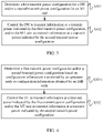
- FIG. 3 is a flowchart of an embodiment of a transmit power configuration method according to this application. As shown in FIG. 3 , the transmit power configuration method includes step S301 and step S302.
- step S301 a first transmit power configuration for a DU and/or a second transmit power configuration for an MT unit are determined.
- the first transmit power configuration is used to indicate a transmit power of the DU.
- the second transmit power configuration is used to indicate a transmit power of the MT unit.
- the IAB node may determine the first transmit power configuration for the DU and/or the second transmit power configuration for the MT unit according to the definition of a protocol.
- the IAB node may determine the first transmit power configuration for the DU and/or the second transmit power configuration for the MT unit based on a configuration from an upstream node.
- the upstream node may be specifically a CU or a parent IAB node of the IAB node. If the upstream node is the parent IAB node of the IAB node, the parent IAB node transmits configuration information to the IAB node through radio resource control (Radio Resource Control, RRC) signaling, F1-C signaling, or the like.
- RRC signaling may include a system information block (System Information Block, SIB), user equipment specific radio resource control (UE-specific RRC), or the like.
- the IAB node may determine the first transmit power configuration for the DU and/or the second transmit power configuration for the MT unit based on configuration information for the DU and the MT unit of the IAB node.
- step S302 the DU is controlled to transmit information at a transmit power indicated by the first transmit power configuration, and/or the MT unit is controlled to transmit information at a transmit power indicated by the second transmit power configuration.
- the DU may transmit information at the transmit power indicated by the first transmit power configuration
- the MT unit may transmit information at the transmit power indicated by the second transmit power configuration.
- the DU may transmit information at the transmit power indicated by the first transmit power configuration, and the MT unit may not transmit information at the transmit power indicated by the second transmit power configuration.
- the DU may not transmit information at the transmit power indicated by the first transmit power configuration, and the MT unit may transmit information at the transmit power indicated by the second transmit power configuration.
- a sum of the transmit power of the DU and the transmit power of the MT unit is less than or equal to a maximum transmit power of the IAB node, so as to avoid a failure of the IAB node to support power transmission of the DU and the MT unit.
- the IAB node determines the first transmit power configuration for the DU and/or the second transmit power configuration for the MT unit, so as to control the DU to transmit information at the transmit power indicated by the first transmit power configuration, and/or control the MT unit to transmit information at the transmit power indicated by the second transmit power configuration.
- the IAB node can configure transmit powers of the DU and the MT unit in advance, and the sum of the transmit power of the DU and the transmit power of the MT unit is less than or equal to the maximum transmit power of the IAB node, so as to implement power sharing between the DU and the MT unit of the IAB node and avoid a conflict between the transmit powers of the DU and the MT unit, thereby improving communication performance of the IAB node.
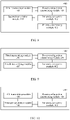
- FIG. 4 is a flowchart of another embodiment of a transmit power configuration method according to this application. A difference between FIG. 4 and FIG. 3 lies in that step S301 in FIG. 3 may be detailed as step S3011 in FIG. 4 .
- a first transmit power configuration and/or a second transmit power configuration are determined based on configuration information transmitted by an upstream node or configuration information obtained by the IAB node.
- the IAB node receives the configuration information transmitted by the upstream node, and determines the first transmit power configuration and/or the second transmit power configuration based on the configuration information.
- the upstream node includes a parent IAB node or a CU. Specifically, the parent IAB node or the CU may transmit the configuration information to the IAB node through RRC signaling or F1-C signaling.
- the IAB node may further report transmit power reference information to the upstream node, so that the upstream node determines, based on the transmit power reference information, power resources to be allocated between the DU and the MT unit, and transmits the configuration information to the IAB node.
- the transmit power reference information may include, but is not limited to, one or more of the following: a maximum expected transmit power of the DU, a minimum expected transmit power of the DU, a maximum expected transmit power of the MT unit, a minimum expected transmit power of the MT unit, an expected ratio of the maximum transmit power of the DU to the maximum transmit power of the MT unit, an expected difference between the maximum transmit power of the DU and the maximum transmit power of the MT unit, or a maximum transmit power of the IAB node.
- the IAB node determines the first transmit power configuration and the second transmit power configuration based on the configuration information obtained by the IAB node.
- the IAB node may further report the obtained configuration information to the upstream node.
- the configuration information in the foregoing embodiment may include, but is not limited to, one or more of the following: a maximum transmit power of the DU, a maximum transmit power of the MT unit, a ratio of the maximum transmit power of the DU to the maximum transmit power of the MT unit, a difference between the maximum transmit power of the DU and the maximum transmit power of the MT unit, a maximum energy per resource element (Energy per Resource Element, EPRE) of the DU, a maximum EPRE of the MT unit, a ratio of the maximum EPRE of the DU to the maximum EPRE of the MT unit, a difference between the maximum EPRE of the DU and the maximum EPRE of the MT unit, a maximum power spectral density (Power Spectrum Density, PSD) of the DU, a maximum PSD of the MT unit, a ratio of the maximum PSD of the DU to the maximum PSD of the MT unit, a difference between the maximum PSD of the DU and the maximum PSD of the MT unit, a minimum transmit power of
- the configuration information determined by the IAB node includes a power reference parameter of the parent IAB node, a target receive power of the parent IAB node, and a total transmit power of the IAB node.
- the power reference parameter includes a reference signal received power (Reference Signal Receiving Power, RSRP) or a path loss (path loss).
- the MT unit of the IAB node may obtain, through measurement, the power reference parameter of the parent IAB node, the target receive power of the parent IAB node, and the total transmit power of the IAB node, and determines the second transmit power configuration for the MT unit based on the power reference parameter of the parent IAB node, the target receive power of the parent IAB node, and the total transmit power of the IAB node.
- a mapping relationship between the power reference parameter and the maximum transmit power of the MT unit may be implemented by using a mapping table.
- the mapping table may be predefined, or may be sent to the IAB node by the CU or an operation and maintenance (operation and maintenance, O&M) server, which is not limited herein.
- the IAB node may control the MT unit to report a power headroom (Power Head Room, PHR) to the upstream node.
- the PHR reported to the upstream node is obtained based on the second transmit power configuration for the MT unit.
- the PHR may be a difference or a ratio between a transmit power of the MT unit and a configured power of the MT unit.
- the configured power of the MT unit may be a maximum transmit power of the MT unit specified in a protocol, a maximum transmit power of the MT unit configured by the upstream node, a maximum transmit power of the MT unit determined by the IAB node, or a maximum transmit power of the MT unit reported by the MT unit, which is not limited herein.
- the MT unit may transmit a plurality of PHRs to the upstream node, which correspond to different configured powers of the MT unit.
- transmission priorities of the DU and the MT unit may be specified by a protocol or preconfigured.
- the upstream node may configure the transmission priorities of the DU and the MT unit through RRC signaling or F1-C signaling.
- the transmission priority may include a priority of a unit and/or a priority of to-be-transmitted information.
- the transmission priority includes a priority of a unit
- a transmission priority of the DU is higher than that of the MT unit
- a transmission priority of the MT unit is higher than that of the DU
- the transmission priorities of the DU and the MT unit are determined based on priorities of to-be-transmitted information of the MT unit and of to-be-transmitted information of the DU.
- the priority of to-be-transmitted information may be set based on specific operating scenarios and operating requirements, which is not limited herein.
- the priorities of to-be-transmitted information in descending order are synchronization signal and PBCH block (Synchronization Signal and PBCH block, SSB) information, physical random access channel (Physical Random Access Channel, PRACH) information, physical downlink control channel (Physical Downlink Control Channel, PDCCH) information/physical uplink control channel (Physical Uplink Control Channel, PUCCH) information, and physical downlink shared channel (Physical Downlink Shared Channel, PDSCH) information/physical uplink shared channel (Physical Uplink Shared Channel, PUSCH) information.
- PBCH block Synchrom Channel
- PRACH Physical Random Access Channel
- PDCCH Physical Downlink Control Channel
- PUCCH Physical Uplink Control Channel
- PDSCH Physical Uplink Shared Channel
- the transmission priority of the MT unit is higher than that of the DU.
- a priority of information of an ultra reliable and low latency communications (Ultra Reliable & Low Latency Communication, URLLC) service is higher than that of information of an enhanced mobile broadband (Enhance Mobile Broadband, eMBB) service.
- Service types of URLLC and eMBB may be distinguished by using a higher layer indication or a physical layer indication.
- a signal to be transmitted by the DU is a target signal
- a priority of the target signal is higher than that of a non-target signal.
- the target signal includes but is not limited to one or more of an SSB signal, a common physical downlink control channel signal (Common PDCCH signal), a user equipment specific physical downlink control channel signal (UE-specific PDCCH signal), a channel state information reference signal (Channel State Information Reference Signal, CSI-RS), or a tracking reference signal (Tracking Reference Signal, TRS).
- SSB signal a common physical downlink control channel signal
- UE-specific PDCCH signal a user equipment specific physical downlink control channel signal
- CSI-RS Channel State Information Reference Signal
- TRS Track Reference Signal
- the IAB node preferentially controls the DU to transmit information at the transmit power indicated by the first transmit power configuration.
- the IAB node may further control the MT unit to perform power scaling (power scaling) or to discard the information.
- the MT unit transmits the information at the transmit power indicated by the second transmit power configuration, which causes a failure of a radio frequency unit of the IAB node to meet the operating requirements, the MT unit is controlled to perform power scaling or to discard the information.
- the failure to meet the operating requirements may be that there is a large power difference or power spectral density difference between the MT unit and the DU.
- the MT unit is controlled to transmit the information at the transmit power indicated by the second transmit power configuration. If the difference between the total transmit power of the IAB node and the transmit power indicated by the first transmit power configuration is less than the transmit power indicated by the second transmit power configuration, the MT unit is controlled to perform power scaling or to discard the information.
- the IAB node preferentially controls the MT unit to transmit information at the transmit power indicated by the second transmit power configuration.
- the IAB node may control the DU to perform power scaling or to discard the information.
- the DU transmits the information at the transmit power indicated by the first transmit power configuration, which causes a failure of a radio frequency unit of the IAB node to meet the operating requirements, the DU is controlled to perform power scaling or to discard the information.
- the failure to meet the operating requirements may be that there is a large power difference or power spectral density difference between the MT unit and the DU.
- the DU is controlled to transmit the information at the transmit power indicated by the first transmit power configuration. If the difference between the total transmit power of the IAB node and the transmit power indicated by the second transmit power configuration is less than the transmit power indicated by the first transmit power configuration, the DU is controlled to perform power scaling or to discard the information.
- Transmission priorities of the target signal and the non-target signal may be further determined by a priority of a unit and a priority of to-be-transmitted information.
- For transmission of the target signal its transmission priority is determined by the priority of to-be-transmitted information, and the priority of the target signal is higher than that of the non-target signal.
- the target signal includes but is not limited to one or more of an SSB signal, a common physical downlink control channel signal (Common PDCCH signal), a user equipment specific physical downlink control channel signal (UE-specific PDCCH signal), a channel state information reference signal (Channel State Information Reference Signal, CSI-RS), or a tracking reference signal (Tracking Reference Signal, TRS).
- Priorities of target signals may also be predefined by a protocol/configured by a control node. For transmission of the non-target signal, its transmission priority is determined by a priority of a unit.
- FIG. 5 is a flowchart of still another embodiment of a transmit power configuration method according to this application. A difference between FIG. 5 and FIG. 3 lies in that step S302 shown in FIG. 3 may be detailed as step S3021 shown in FIG. 5 .
- a DU is controlled to transmit, in a target time period, information at a transmit power indicated by a first transmit power configuration, and/or an MT unit is controlled to transmit, in the target time period, information at a transmit power indicated by a second transmit power configuration.
- the target time period may include, but is not limited to, at least one of the following: a time period during which both the DU and the MT unit transmit information; a symbol (symbol) or a symbol set occupied by a downlink resource configured for the DU and an uplink resource configured for the MT unit in time domain; a slot (slot) or a sub-slot (sub-slot) containing in time domain the symbol occupied by the downlink resource configured for the DU and the uplink resource configured for the MT unit; or a slot set or a sub-slot set containing in time domain the symbol occupied by the downlink resource configured for the DU and the uplink resource configured for the MT unit.
- the downlink (Downlink, DL) resource for the DU may be configured.
- the uplink (Uplink, UL) resource for the MT unit may be configured.
- the DU transmits the information in the symbol or the symbol set occupied by the configured downlink resource, the slot or the sub-slot containing the symbol occupied by the downlink resource configured for the DU, or the slot set or the sub-slot set containing the symbol occupied by the downlink resource configured for the DU; and the MT unit transmits the information in the symbol or the symbol set occupied by the configured uplink resource, the slot or the sub-slot containing the symbol occupied by the uplink resource configured for the MT unit, or the slot set or the sub-slot set containing the symbol occupied by the uplink resource configured for the MT unit.
- the slot set includes at least one slot.
- the sub-slot set includes at least one sub-slot.
- the slot set includes a number of consecutive slots.
- the sub-slot set includes a number of consecutive sub-slots.
- a start time and a length of the symbol, symbol set, slot, sub-slot, slot set, or sub-slot set occupied by the downlink resource for the DU may be configured by an upstream node.
- the start time may be implemented by a relative start time and an offset (offset).
- the length may be implemented by the number of symbols, slots, sub-slots, slot sets, or sub-slot sets.
- the start time and the length may be configured through RRC signaling or F1-C signaling.
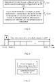
- FIG. 6 is a schematic diagram of an example of a time period occupied by a downlink resource for a DU according to an embodiment of this application.
- a relative start time is SFN #0
- an offset is offset
- a length is N slots, from Slot #n+l to Slot #n+N.
- a dynamic range in which the transmit power configurations for the DU and the MT unit take effect in time domain can be controlled.
- the DU in a time period that is occupied by the downlink resource for the DU and the uplink resource for the MT unit and that is specified by a protocol or configured by an upstream node, the DU may be controlled to transmit information at the transmit power indicated by the first transmit power configuration, and the MT unit may be controlled to transmit information at the transmit power indicated by the second transmit power configuration.
- the transmit power of the DU and the transmit power of the MT unit are not subject to power sharing.
- the transmit power of the DU is less than or equal to a difference between a maximum transmit power of the IAB node and the maximum transmit power of the MT unit. In other time periods, the transmit power of the DU may be less than or equal to the maximum transmit power of the IAB node.
- the DU may discard the target signal during the target time period.
- a transmit power of the target signal is the transmit power indicated by the first transmit power configuration.
- the DU transmits the target signal at the transmit power of the target signal indicated by the first transmit power configuration.
- the first transmit power configuration includes a power configuration for the target signal and a power configuration for a non-target signal.
- the power configuration for the target signal and the power configuration for the non-target signal may use independent power configurations or the same power configuration.
- the transmit power of the target signal may be a transmit power when the DU uses a conventional information transmission method.
- the transmit power of the target signal may be a maximum transmit power of the DU.
- the target signal is a specified special signal.
- the target signal may include, but is not limited to, one or more of the following: an SSB signal, a common PDCCH signal, a UE-specific PDCCH signal, a CSI-RS, or a TRS.
- the IAB node may further report a resource position of the target signal to the upstream node.
- the resource position may be specifically a determined resource position or a potential resource position.
- the resource position may specifically include a time domain resource position and/or a frequency domain resource position, which is not limited herein.
- the IAB node reports the resource position of the target signal to the upstream node, so that when the upstream node configures powers for the DU and the MT unit of the IAB node, the upstream node can be prevented from configuring the MT unit to transmit information in a case where the DU transmits the target signal.
- the IAB node may further transmit power indication information to a terminal device.
- the power indication information is used to indicate one or more of the following: whether the DU and the MT unit share a total transmit power of the IAB node, the transmit power of the DU and/or the MT unit, a difference between the transmit power of the DU and/or the MT unit and a reference power, a ratio of the transmit power of the DU and/or the MT unit to the reference power, a difference between the transmit power of the DU and the transmit power of the MT unit, or a ratio of the transmit power of the DU to the transmit power of the unit.
- the reference power may be obtained based on the first transmit power configuration for the DU, which is not limited herein.
- the power indication information may be carried in power execution signaling for transmission.
- the power execution signaling may be physical layer signaling or higher layer signaling, for example, a media access control layer control element (Media Access Control Control Element, MAC CE), or downlink control information (Downlink Control Information, DCI), which is not limited herein.
- Media Access Control Control Element Media Access Control Control Element, MAC CE
- DCI Downlink Control Information
- the power indication information may assist the terminal device in adjusting AGC, and help the terminal device perform reference signal measurement and reference signal quality estimation.
- the transmit power of the DU varies in different scenarios.
- the terminal device performs an AGC adjustment.
- the IAB node may set a transitional time period when switching from a first scenario to a second scenario. The transitional time period is used for AGC adjustment by the terminal device communicating with the IAB node.
- the first scenario may include one of the following: the DU transmits information and the MT unit performs no information transmission, the DU transmits information and the MT unit transmits information, the DU transmits information and the MT unit receives information, or the DU receives information and the MT unit transmits information.
- the second scenario may include one of the following: the DU transmits information and the MT unit performs no information transmission, the DU transmits information and the MT unit transmits information, the DU transmits information and the MT unit receives information, or the DU receives information and the MT unit transmits information.
- the first scenario is different from the second scenario.
- a time period corresponding to the scenario in which the DU transmits information and the MT unit performs no information transmission is a time period in which a downlink resource for the DU has been configured for the DU but no resource has been configured for the MT unit.
- a time period corresponding to the scenario in which the DU transmits information and the MT unit transmits information is a time period in which a downlink resource has been configured for the DU and an uplink resource has been configured for the MT unit.
- a time period corresponding to the scenario in which the DU transmits information and the MT unit receives information is a time period in which a downlink resource has been configured for the DU and a downlink resource has been configured for the MT unit.
- a time period corresponding to the scenario in which the DU receives information and the MT unit transmits information is a time period in which an uplink resource has been configured for the DU and an uplink resource has been configured for the MT unit.
- the IAB transmits specified information or stops information transmission during the transitional time period.
- the specified information is information specified by a protocol or preconfigured, which is not limited herein.
- the specified information may be fixed sequence (sequence) information, or information in a next time period, or any information transmitted by the DU.
- the IAB node may further report to the upstream node whether the DU and the MT unit share a radio frequency unit. For example, one information bit in the information may be used to indicate whether the DU and the MT unit share the same radio frequency unit.
- FIG. 7 is a schematic structural diagram of an embodiment of an IAB node according to this application.
- the IAB node 400 includes a power configuration determining module 401 and a transmission control module 402.
- the power configuration determining module 401 is configured to determine a first transmit power configuration for the DU and/or a second transmit power configuration for the MT unit.
- the transmission control module 402 is configured to control the DU to transmit information at a transmit power indicated by the first transmit power configuration, and/or the MT unit to transmit information at a transmit power indicated by the second transmit power configuration.
- a sum of the transmit power of the DU and the transmit power of the MT unit is less than or equal to a maximum transmit power of the IAB node.
- the IAB node determines the first transmit power configuration for the DU and/or the second transmit power configuration for the MT unit, so as to control the DU to transmit information at the transmit power indicated by the first transmit power configuration, and/or control the MT unit to transmit information at the transmit power indicated by the second transmit power configuration.
- the IAB node can configure transmit powers of the DU and the MT unit in advance, and the sum of the transmit power of the DU and the transmit power of the MT unit is less than or equal to the maximum transmit power of the IAB node, so as to implement power sharing between the DU and the MT unit of the IAB node and avoid a conflict between the transmit powers of the DU and the MT unit, thereby improving communication performance of the IAB node.
- FIG. 8 is a schematic structural diagram of another embodiment of an IAB node according to this application. A difference between FIG. 8 and FIG. 7 lies in that the IAB node shown in FIG. 8 may further include a first transmitting module 403, a second transmitting module 404, and a priority determining module 405.
- the power configuration determining module 401 in the foregoing embodiment may be specifically configured to determine a first transmit power configuration and/or a second transmit power configuration based on configuration information transmitted by an upstream node or configuration information obtained by the IAB node.
- the upstream node includes a parent IAB node or a CU.
- the first transmitting module 403 is configured to report the configuration information obtained by the IAB node to the upstream node.
- the configuration information includes one or more of the following: a maximum transmit power of the DU, a maximum transmit power of the MT unit, a ratio of the maximum transmit power of the DU to the maximum transmit power of the MT unit, a difference between the maximum transmit power of the DU and the maximum transmit power of the MT unit, a maximum energy per resource element of the DU, a maximum energy per resource element of the MT unit, a ratio of the maximum energy per resource element of the DU to the maximum energy per resource element of the MT unit, a difference between the maximum energy per resource element of the DU and the maximum energy per resource element of the MT unit, a maximum power spectral density of the DU, a maximum power spectral density of the MT unit, a ratio of the maximum power spectral density of the DU to the maximum power spectral density of the MT unit, a difference between the maximum power spectral density of the DU and the maximum power spectral density of the MT unit, a minimum transmit power of the DU
- the configuration information determined by the IAB node includes a power reference parameter of the parent IAB node, a target receive power of the parent IAB node, and a total transmit power of the IAB node.
- the power reference parameter includes a reference signal received power or a path loss.
- the transmission control module 402 in the foregoing embodiment may be further configured to control the MT unit to report a power headroom PHR to an upstream node.
- the upstream node includes a parent IAB node or a CU.
- the PHR reported to the upstream node is obtained based on the second transmit power configuration for the MT unit.
- the second transmitting module 404 is configured to report transmit power reference information to an upstream node.
- the upstream node includes a parent IAB node or a CU.
- the transmit power reference information includes one or more of the following: a maximum expected transmit power of the DU, a minimum expected transmit power of the DU, a maximum expected transmit power of the MT unit, a minimum expected transmit power of the MT unit, an expected ratio of the maximum transmit power of the DU to the maximum transmit power of the MT unit, an expected difference between the maximum transmit power of the DU and the maximum transmit power of the MT unit, or a maximum transmit power of the IAB node.
- the priority determining module 405 is configured to determine transmission priorities of the DU and the MT unit.
- the transmission control module 402 controls the DU to transmit information at the transmit power indicated by the first transmit power configuration.
- the transmission control module 402 controls the MT unit to transmit information at the transmit power indicated by the second transmit power configuration.
- the transmission priority includes a priority of a unit and/or a priority of to-be-transmitted information.
- the transmission control module 402 is further configured to control the MT unit to perform power scaling or to discard the information. If the transmission priority of the MT unit is higher than that of the DU, the transmission control module 402 is further configured to control the DU to perform power scaling or to discard the information.
- FIG. 9 is a schematic structural diagram of still another embodiment of an IAB node according to this application. A difference between FIG. 9 and FIG. 7 lies in that the IAB node shown in FIG. 9 may further include a third transmitting module 406 and a fourth transmitting module 407.
- the transmission control module 402 in the foregoing embodiment is specifically configured to control a DU to transmit, in a target time period, information at a transmit power indicated by a first transmit power configuration, and/or an MT unit to transmit, in the target time period, information at a transmit power indicated by a second transmit power configuration.
- the target time period includes at least one of the following: a time period during which both the DU and the MT unit transmit information; a symbol or a symbol set occupied by a downlink resource configured for the DU and an uplink resource configured for the MT unit in time domain; a slot or a sub-slot containing in time domain the symbol occupied by the downlink resource configured for the DU and the uplink resource configured for the MT unit; or a slot set or a sub-slot set containing in time domain the symbol occupied by the downlink resource configured for the DU and the uplink resource configured for the MT unit.
- the target signal includes one or more of an SSB signal, a common PDCCH signal, a UE specific PDCCH signal, a CSI-RS, or a TRS.
- a transmit power of the target signal may be the transmit power indicated by the first transmit power configuration.
- the first transmit power configuration includes a power configuration for the target signal and a power configuration for a non-target signal.
- the third transmitting module 406 is configured to report a resource position of the target signal to an upstream node, where the upstream node includes a parent IAB node or a CU.
- the fourth transmitting module 407 is configured to transmit power indication information to a terminal device.
- the power indication information is used to indicate one or more of the following: whether the DU and the MT unit share a total transmit power of the IAB node, the transmit power of the DU and/or the MT unit, a difference between the transmit power of the DU and/or the MT unit and a reference power, a ratio of the transmit power of the DU and/or the MT unit to the reference power, a difference between the transmit power of the DU and the transmit power of the MT unit, or a ratio of the transmit power of the DU to the transmit power of the unit.
- FIG. 10 is a schematic structural diagram of yet another embodiment of an IAB node according to this application.
- the time period setting module 408 is configured to: when a first scenario is switched to a second scenario, set a transitional time period, where the transitional time period is used for automatic gain control adjustment by a terminal device communicating with the IAB node.
- the first scenario includes one of the following: a DU transmits information and an MT unit performs no information transmission, the DU transmits information and the MT unit transmits information, the DU transmits information and the MT unit receives information, or the DU receives information and the MT unit transmits information.
- the second scenario includes one of the following: the DU transmits information and the MT unit performs no information transmission, the DU transmits information and the MT unit transmits information, the DU transmits information and the MT unit receives information, or the DU receives information and the MT unit transmits information.
- the first scenario is different from the second scenario.
- the fifth transmitting module 409 is configured to transmit specified information or stop information transmission during the transitional time period.
- FIG. 11 is a schematic hardware structure diagram of an example of a base station that implements the embodiments of this application.
- the base station 500 includes: a memory 501, a processor 502, a radio frequency unit 503, and a computer program stored on the memory 501 and executable on the processor 502.
- the structure of the base station shown in FIG. 11 does not constitute a limitation to the base station.
- the base station may include more or fewer components than those shown in the figure, or some components may be combined, or there may be a different component arrangement.
- the processor 502 is configured to determine a first transmit power configuration for the DU and/or a second transmit power configuration for the MT unit; and configured to control the DU to transmit information at a transmit power indicated by the first transmit power configuration, and/or the MT unit to transmit information at a transmit power indicated by the second transmit power configuration.
- a bus architecture may include any number of interconnected buses and bridges, and link together one or more processors specifically represented by the processor 502 and various circuits of a memory represented by memory 501.
- the bus architecture may further link together various other circuits, such as a peripheral device, a voltage regulator, and a power management circuit, which are well known in the art and therefore are not further described herein.
- a bus interface provides an interface.
- the radio frequency unit 503 may be a plurality of elements, including a transmitter and a receiver providing a unit for communicating with various other apparatuses over a transmission medium, to receive and transmit data under the control of the processor 502.
- the processor 502 is responsible for managing the bus architecture and general processing, and the memory 501 may store data used by the processor 502 when performing an operation.
- an embodiment of this application further provides a base station, including a processor 502, a memory 501, and a computer program stored on the memory 501 and executable on the processor 502.
- a base station including a processor 502, a memory 501, and a computer program stored on the memory 501 and executable on the processor 502.
- the processes of the foregoing transmit power configuration method embodiments applied to an IAB node shown in FIG. 3 to FIG. 5 are implemented, with the same technical effects achieved. To avoid repetition, details are not described herein again.
- An embodiment of this application further provides a computer-readable storage medium.
- the computer-readable storage medium stores a computer program, and when the computer program is executed by a processor, the processes of the foregoing transmit power configuration method embodiments applied to an IAB node are implemented, with the same technical effects achieved. To avoid repetition, details are not described herein again.
- the computer-readable storage medium is, for example, a read-only memory (Read-Only Memory, ROM for short), a random access memory (Random Access Memory, RAM for short), a magnetic disk, an optical disc, or the like.
- the transmit power configuration method, the IAB node, the base station, and the storage medium in the foregoing embodiments can be applied to a 5G communications system and a later communications system, which is not limited herein.
- the computer software product is stored in a storage medium (such as a ROM/RAM, a magnetic disk, or an optical disc), and includes several instructions for instructing a terminal (which may be a mobile phone, a computer, a server, an air conditioner, a network device, or the like) to perform the methods described in the embodiments of this application.
- a storage medium such as a ROM/RAM, a magnetic disk, or an optical disc
- a terminal which may be a mobile phone, a computer, a server, an air conditioner, a network device, or the like
- Such a processor may be, but is not limited to, a general-purpose processor, a dedicated processor, a special application processor, or a field-programmable logic circuit. It may be further understood that each block in the block diagrams and/or the flowcharts, and a combination of the blocks in the block diagrams and/or the flowcharts may also be implemented by dedicated hardware that executes specified functions or actions, or may be implemented by a combination of dedicated hardware and computer instructions.
Landscapes
- Engineering & Computer Science (AREA)
- Computer Networks & Wireless Communication (AREA)
- Signal Processing (AREA)
- Mobile Radio Communication Systems (AREA)
- Transmitters (AREA)
Applications Claiming Priority (2)
| Application Number | Priority Date | Filing Date | Title |
|---|---|---|---|
| CN202010076424.1A CN113163490B (zh) | 2020-01-23 | 2020-01-23 | 发送功率配置方法、iab节点、基站及存储介质 |
| PCT/CN2021/072672 WO2021147847A1 (zh) | 2020-01-23 | 2021-01-19 | 发送功率配置方法、iab节点、基站及存储介质 |
Publications (3)
| Publication Number | Publication Date |
|---|---|
| EP4096324A1 true EP4096324A1 (de) | 2022-11-30 |
| EP4096324A4 EP4096324A4 (de) | 2023-06-28 |
| EP4096324B1 EP4096324B1 (de) | 2025-10-15 |
Family
ID=76881960
Family Applications (1)
| Application Number | Title | Priority Date | Filing Date |
|---|---|---|---|
| EP21744404.1A Active EP4096324B1 (de) | 2020-01-23 | 2021-01-19 | Konfiguration der übertragungsleistung an einem iab-knoten |
Country Status (8)
| Country | Link |
|---|---|
| US (1) | US12389343B2 (de) |
| EP (1) | EP4096324B1 (de) |
| JP (1) | JP7562680B2 (de) |
| KR (1) | KR20220130195A (de) |
| CN (2) | CN116600376B (de) |
| ES (1) | ES3050620T3 (de) |
| PH (1) | PH12022551535A1 (de) |
| WO (1) | WO2021147847A1 (de) |
Families Citing this family (6)
| Publication number | Priority date | Publication date | Assignee | Title |
|---|---|---|---|---|
| EP4106408A4 (de) * | 2020-02-14 | 2023-03-29 | Huawei Technologies Co., Ltd. | Ressourcenkonfigurationsverfahren und -vorrichtung |
| US12376045B2 (en) | 2020-03-27 | 2025-07-29 | Sharp Kabushiki Kaisha | Power reporting for integrated access and backhaul networks |
| US12058589B2 (en) * | 2021-01-14 | 2024-08-06 | Qualcomm Incorporated | Selective forwarding of RRC reconfiguration messages in IAB |
| US11974232B2 (en) * | 2021-12-07 | 2024-04-30 | Qualcomm Incorporated | Coordination of transmit power for distributed units |
| US12574852B2 (en) * | 2023-01-13 | 2026-03-10 | Rakuten Mobile, Inc. | Auto-recovery device, method, and computer-readable medium |
| KR20250122242A (ko) * | 2024-02-06 | 2025-08-13 | 삼성전자주식회사 | 무선 통신 시스템에서 수신 모드를 변경하기 위한 방법 및 장치 |
Family Cites Families (19)
| Publication number | Priority date | Publication date | Assignee | Title |
|---|---|---|---|---|
| JP5669664B2 (ja) | 2011-05-16 | 2015-02-12 | 京セラ株式会社 | 無線基地局及び通信制御方法 |
| US8639282B2 (en) * | 2011-06-14 | 2014-01-28 | Futurewei Technologies, Inc. | System and method for uplink power control in a communications system |
| KR20170123236A (ko) * | 2016-04-28 | 2017-11-07 | 엘지전자 주식회사 | 데이터 볼륨 정보를 전송하는 방법 및 사용자기기 |
| US11026186B2 (en) | 2017-10-27 | 2021-06-01 | Qualcomm Incorporated | Power control for concurrent reception |
| US11165545B2 (en) * | 2017-10-27 | 2021-11-02 | Qualcomm Incorporated | Power control for concurrent transmissions |
| US10827499B2 (en) * | 2017-10-30 | 2020-11-03 | Qualcomm Incorporated | Techniques and apparatuses for prioritization for transmission power control in 5G |
| US10798661B2 (en) * | 2017-10-30 | 2020-10-06 | Qualcomm Incorporated | Techniques and apparatuses for resource-specific power control in 5G |
| CN114499604A (zh) | 2018-01-25 | 2022-05-13 | 成都华为技术有限公司 | 一种功率控制方法及装置 |
| CN110351807B (zh) | 2018-04-04 | 2023-07-14 | 中兴通讯股份有限公司 | 接入选择方法及装置 |
| US20190394687A1 (en) * | 2018-06-22 | 2019-12-26 | Sharp Laboratories Of America, Inc. | Integrated Access and Backhaul Next Generation NodeB Capabilities and Signaling |
| EP3815324B1 (de) * | 2018-06-26 | 2025-08-20 | Nokia Technologies Oy | Dynamische routenauswahl in einem integrierten zugangs- und backhaul-system |
| US10470136B1 (en) * | 2018-08-10 | 2019-11-05 | At&T Intellectual Property I, L.P. | Downlink power control enhancements for multi-hop integrated access and backhaul |
| EP3834508A1 (de) * | 2018-08-10 | 2021-06-16 | Telefonaktiebolaget LM Ericsson (publ) | Meldungsbestimmung für leistungsreservenbericht (phr) |
| US11252718B2 (en) * | 2018-11-01 | 2022-02-15 | Qualcomm Incorporated | Configuration of resource patterns for integrated access and backhaul |
| EP3903422A1 (de) * | 2018-12-24 | 2021-11-03 | Telefonaktiebolaget LM Ericsson (publ) | Iab-leistungssteuerung |
| CN110536352B (zh) * | 2019-02-14 | 2024-12-03 | 中兴通讯股份有限公司 | 信息配置及资源预申请方法、装置、节点及存储介质 |
| CN110536351B (zh) * | 2019-02-15 | 2024-06-04 | 中兴通讯股份有限公司 | Iab网络中信息处理方法、iab及计算机存储介质 |
| US12323927B2 (en) * | 2019-07-26 | 2025-06-03 | Sharp Kabushiki Kaisha | Power management for integrated access and backhaul networks |
| CN113973374B (zh) * | 2020-07-24 | 2025-04-11 | 维沃移动通信有限公司 | 功率获取方法、装置及节点设备 |
-
2020
- 2020-01-23 CN CN202310531333.6A patent/CN116600376B/zh active Active
- 2020-01-23 CN CN202010076424.1A patent/CN113163490B/zh active Active
-
2021
- 2021-01-19 ES ES21744404T patent/ES3050620T3/es active Active
- 2021-01-19 WO PCT/CN2021/072672 patent/WO2021147847A1/zh not_active Ceased
- 2021-01-19 JP JP2022544722A patent/JP7562680B2/ja active Active
- 2021-01-19 PH PH1/2022/551535A patent/PH12022551535A1/en unknown
- 2021-01-19 EP EP21744404.1A patent/EP4096324B1/de active Active
- 2021-01-19 KR KR1020227028625A patent/KR20220130195A/ko active Pending
-
2022
- 2022-06-23 US US17/847,288 patent/US12389343B2/en active Active
Also Published As
| Publication number | Publication date |
|---|---|
| ES3050620T3 (en) | 2025-12-22 |
| US12389343B2 (en) | 2025-08-12 |
| JP7562680B2 (ja) | 2024-10-07 |
| JP2023511422A (ja) | 2023-03-17 |
| EP4096324A4 (de) | 2023-06-28 |
| CN113163490B (zh) | 2023-04-18 |
| CN113163490A (zh) | 2021-07-23 |
| WO2021147847A1 (zh) | 2021-07-29 |
| CN116600376A (zh) | 2023-08-15 |
| US20220322249A1 (en) | 2022-10-06 |
| KR20220130195A (ko) | 2022-09-26 |
| PH12022551535A1 (en) | 2023-07-31 |
| CN116600376B (zh) | 2025-10-31 |
| EP4096324B1 (de) | 2025-10-15 |
Similar Documents
| Publication | Publication Date | Title |
|---|---|---|
| US12389343B2 (en) | Transmit power configuration method, IAB node, base station, and storage medium | |
| US12238652B2 (en) | Method of power control for uplink transmission | |
| CN109561508B (zh) | 时分双工无线通信系统 | |
| US20170111870A1 (en) | System and Method for Direct Mobile Communications Power Control | |
| US12376045B2 (en) | Power reporting for integrated access and backhaul networks | |
| US20220346088A1 (en) | Multiplexing scheduling method for iab network and iab node | |
| US12483998B2 (en) | Power adjustment method and node device | |
| JP7662820B2 (ja) | 複数のスロットにわたるトランスポートブロック送信のためのul電力制御 | |
| EP4164315B1 (de) | Leistungserfassungsverfahren und -vorrichtung sowie knotenvorrichtung | |
| US20240155627A1 (en) | Resource configuration method and communication apparatus | |
| HK40080085A (en) | Sending power configuration method, iab node, base station and storage medium | |
| HK40076783A (en) | Multiplexing scheduling method for iab network and iab node |
Legal Events
| Date | Code | Title | Description |
|---|---|---|---|
| STAA | Information on the status of an ep patent application or granted ep patent |
Free format text: STATUS: THE INTERNATIONAL PUBLICATION HAS BEEN MADE |
|
| PUAI | Public reference made under article 153(3) epc to a published international application that has entered the european phase |
Free format text: ORIGINAL CODE: 0009012 |
|
| STAA | Information on the status of an ep patent application or granted ep patent |
Free format text: STATUS: REQUEST FOR EXAMINATION WAS MADE |
|
| 17P | Request for examination filed |
Effective date: 20220808 |
|
| AK | Designated contracting states |
Kind code of ref document: A1 Designated state(s): AL AT BE BG CH CY CZ DE DK EE ES FI FR GB GR HR HU IE IS IT LI LT LU LV MC MK MT NL NO PL PT RO RS SE SI SK SM TR |
|
| DAV | Request for validation of the european patent (deleted) | ||
| DAX | Request for extension of the european patent (deleted) | ||
| REG | Reference to a national code |
Ref country code: HK Ref legal event code: DE Ref document number: 40080085 Country of ref document: HK |
|
| REG | Reference to a national code |
Ref country code: DE Ref legal event code: R079 Free format text: PREVIOUS MAIN CLASS: H04W0072040000 Ipc: H04W0052240000 Ref country code: DE Ref legal event code: R079 Ref document number: 602021040454 Country of ref document: DE Free format text: PREVIOUS MAIN CLASS: H04W0072040000 Ipc: H04W0052240000 |
|
| A4 | Supplementary search report drawn up and despatched |
Effective date: 20230531 |
|
| RIC1 | Information provided on ipc code assigned before grant |
Ipc: H04W 72/04 20090101ALI20230524BHEP Ipc: H04W 52/24 20090101AFI20230524BHEP |
|
| GRAP | Despatch of communication of intention to grant a patent |
Free format text: ORIGINAL CODE: EPIDOSNIGR1 |
|
| STAA | Information on the status of an ep patent application or granted ep patent |
Free format text: STATUS: GRANT OF PATENT IS INTENDED |
|
| INTG | Intention to grant announced |
Effective date: 20250602 |
|
| GRAS | Grant fee paid |
Free format text: ORIGINAL CODE: EPIDOSNIGR3 |
|
| GRAA | (expected) grant |
Free format text: ORIGINAL CODE: 0009210 |
|
| STAA | Information on the status of an ep patent application or granted ep patent |
Free format text: STATUS: THE PATENT HAS BEEN GRANTED |
|
| AK | Designated contracting states |
Kind code of ref document: B1 Designated state(s): AL AT BE BG CH CY CZ DE DK EE ES FI FR GB GR HR HU IE IS IT LI LT LU LV MC MK MT NL NO PL PT RO RS SE SI SK SM TR |
|
| REG | Reference to a national code |
Ref country code: GB Ref legal event code: FG4D Ref country code: CH Ref legal event code: F10 Free format text: ST27 STATUS EVENT CODE: U-0-0-F10-F00 (AS PROVIDED BY THE NATIONAL OFFICE) Effective date: 20251015 |
|
| REG | Reference to a national code |
Ref country code: DE Ref legal event code: R096 Ref document number: 602021040454 Country of ref document: DE |
|
| REG | Reference to a national code |
Ref country code: IE Ref legal event code: FG4D |
|
| REG | Reference to a national code |
Ref country code: NL Ref legal event code: FP |
|
| REG | Reference to a national code |
Ref country code: ES Ref legal event code: FG2A Ref document number: 3050620 Country of ref document: ES Kind code of ref document: T3 Effective date: 20251222 |
|
| PGFP | Annual fee paid to national office [announced via postgrant information from national office to epo] |
Ref country code: GB Payment date: 20251127 Year of fee payment: 6 |
|
| PGFP | Annual fee paid to national office [announced via postgrant information from national office to epo] |
Ref country code: FR Payment date: 20251128 Year of fee payment: 6 Ref country code: NL Payment date: 20251215 Year of fee payment: 6 |
|
| REG | Reference to a national code |
Ref country code: AT Ref legal event code: MK05 Ref document number: 1848212 Country of ref document: AT Kind code of ref document: T Effective date: 20251015 |
|
| PGFP | Annual fee paid to national office [announced via postgrant information from national office to epo] |
Ref country code: ES Payment date: 20260212 Year of fee payment: 6 |
|
| REG | Reference to a national code |
Ref country code: LT Ref legal event code: MG9D |
|
| PG25 | Lapsed in a contracting state [announced via postgrant information from national office to epo] |
Ref country code: NO Free format text: LAPSE BECAUSE OF FAILURE TO SUBMIT A TRANSLATION OF THE DESCRIPTION OR TO PAY THE FEE WITHIN THE PRESCRIBED TIME-LIMIT Effective date: 20260115 |
|
| PGFP | Annual fee paid to national office [announced via postgrant information from national office to epo] |
Ref country code: DE Payment date: 20251203 Year of fee payment: 6 |
|
| PG25 | Lapsed in a contracting state [announced via postgrant information from national office to epo] |
Ref country code: AT Free format text: LAPSE BECAUSE OF FAILURE TO SUBMIT A TRANSLATION OF THE DESCRIPTION OR TO PAY THE FEE WITHIN THE PRESCRIBED TIME-LIMIT Effective date: 20251015 Ref country code: HR Free format text: LAPSE BECAUSE OF FAILURE TO SUBMIT A TRANSLATION OF THE DESCRIPTION OR TO PAY THE FEE WITHIN THE PRESCRIBED TIME-LIMIT Effective date: 20251015 Ref country code: FI Free format text: LAPSE BECAUSE OF FAILURE TO SUBMIT A TRANSLATION OF THE DESCRIPTION OR TO PAY THE FEE WITHIN THE PRESCRIBED TIME-LIMIT Effective date: 20251015 |
|
| PG25 | Lapsed in a contracting state [announced via postgrant information from national office to epo] |
Ref country code: RS Free format text: LAPSE BECAUSE OF FAILURE TO SUBMIT A TRANSLATION OF THE DESCRIPTION OR TO PAY THE FEE WITHIN THE PRESCRIBED TIME-LIMIT Effective date: 20260115 |
|
| PG25 | Lapsed in a contracting state [announced via postgrant information from national office to epo] |
Ref country code: IS Free format text: LAPSE BECAUSE OF FAILURE TO SUBMIT A TRANSLATION OF THE DESCRIPTION OR TO PAY THE FEE WITHIN THE PRESCRIBED TIME-LIMIT Effective date: 20260215 |
|
| PG25 | Lapsed in a contracting state [announced via postgrant information from national office to epo] |
Ref country code: PT Free format text: LAPSE BECAUSE OF FAILURE TO SUBMIT A TRANSLATION OF THE DESCRIPTION OR TO PAY THE FEE WITHIN THE PRESCRIBED TIME-LIMIT Effective date: 20260216 |
|
| PG25 | Lapsed in a contracting state [announced via postgrant information from national office to epo] |
Ref country code: PL Free format text: LAPSE BECAUSE OF FAILURE TO SUBMIT A TRANSLATION OF THE DESCRIPTION OR TO PAY THE FEE WITHIN THE PRESCRIBED TIME-LIMIT Effective date: 20251015 |
|
| PG25 | Lapsed in a contracting state [announced via postgrant information from national office to epo] |
Ref country code: LV Free format text: LAPSE BECAUSE OF FAILURE TO SUBMIT A TRANSLATION OF THE DESCRIPTION OR TO PAY THE FEE WITHIN THE PRESCRIBED TIME-LIMIT Effective date: 20251015 |