EP4096377A1 - Armoire de commande pour l'électronique de puissance - Google Patents
Armoire de commande pour l'électronique de puissance Download PDFInfo
- Publication number
- EP4096377A1 EP4096377A1 EP21176257.0A EP21176257A EP4096377A1 EP 4096377 A1 EP4096377 A1 EP 4096377A1 EP 21176257 A EP21176257 A EP 21176257A EP 4096377 A1 EP4096377 A1 EP 4096377A1
- Authority
- EP
- European Patent Office
- Prior art keywords
- heat exchanger
- switch cabinet
- cooling circuit
- power electronics
- cooling
- Prior art date
- Legal status (The legal status is an assumption and is not a legal conclusion. Google has not performed a legal analysis and makes no representation as to the accuracy of the status listed.)
- Withdrawn
Links
- 238000001816 cooling Methods 0.000 claims abstract description 86
- 239000002826 coolant Substances 0.000 claims abstract description 10
- 238000004519 manufacturing process Methods 0.000 claims abstract description 3
- 238000009434 installation Methods 0.000 claims description 20
- 230000001681 protective effect Effects 0.000 claims description 8
- 230000001066 destructive effect Effects 0.000 claims description 2
- 238000011161 development Methods 0.000 description 5
- 230000018109 developmental process Effects 0.000 description 5
- 238000000034 method Methods 0.000 description 5
- XLYOFNOQVPJJNP-UHFFFAOYSA-N water Substances O XLYOFNOQVPJJNP-UHFFFAOYSA-N 0.000 description 4
- 238000005516 engineering process Methods 0.000 description 3
- 239000007788 liquid Substances 0.000 description 3
- 238000010616 electrical installation Methods 0.000 description 2
- 239000002918 waste heat Substances 0.000 description 2
- 238000010146 3D printing Methods 0.000 description 1
- 238000010276 construction Methods 0.000 description 1
- 230000001419 dependent effect Effects 0.000 description 1
- 238000007599 discharging Methods 0.000 description 1
- 230000000694 effects Effects 0.000 description 1
- 230000007613 environmental effect Effects 0.000 description 1
Images

Classifications
-
- H—ELECTRICITY
- H05—ELECTRIC TECHNIQUES NOT OTHERWISE PROVIDED FOR
- H05K—PRINTED CIRCUITS; CASINGS OR CONSTRUCTIONAL DETAILS OF ELECTRIC APPARATUS; MANUFACTURE OF ASSEMBLAGES OF ELECTRICAL COMPONENTS
- H05K7/00—Constructional details common to different types of electric apparatus
- H05K7/20—Modifications to facilitate cooling, ventilating, or heating
- H05K7/2089—Modifications to facilitate cooling, ventilating, or heating for power electronics, e.g. for inverters for controlling motor
- H05K7/20927—Liquid coolant without phase change
-
- H—ELECTRICITY
- H05—ELECTRIC TECHNIQUES NOT OTHERWISE PROVIDED FOR
- H05K—PRINTED CIRCUITS; CASINGS OR CONSTRUCTIONAL DETAILS OF ELECTRIC APPARATUS; MANUFACTURE OF ASSEMBLAGES OF ELECTRICAL COMPONENTS
- H05K7/00—Constructional details common to different types of electric apparatus
- H05K7/20—Modifications to facilitate cooling, ventilating, or heating
- H05K7/20536—Modifications to facilitate cooling, ventilating, or heating for racks or cabinets of standardised dimensions, e.g. electronic racks for aircraft or telecommunication equipment
- H05K7/20627—Liquid coolant without phase change
- H05K7/20645—Liquid coolant without phase change within cabinets for removing heat from sub-racks
-
- H—ELECTRICITY
- H05—ELECTRIC TECHNIQUES NOT OTHERWISE PROVIDED FOR
- H05K—PRINTED CIRCUITS; CASINGS OR CONSTRUCTIONAL DETAILS OF ELECTRIC APPARATUS; MANUFACTURE OF ASSEMBLAGES OF ELECTRICAL COMPONENTS
- H05K7/00—Constructional details common to different types of electric apparatus
- H05K7/20—Modifications to facilitate cooling, ventilating, or heating
- H05K7/20536—Modifications to facilitate cooling, ventilating, or heating for racks or cabinets of standardised dimensions, e.g. electronic racks for aircraft or telecommunication equipment
- H05K7/20554—Forced ventilation of a gaseous coolant
- H05K7/20572—Forced ventilation of a gaseous coolant within cabinets for removing heat from sub-racks, e.g. plenum
Definitions
- the invention relates to a switch cabinet according to the preamble of patent claim 1 and a method for producing a switch cabinet according to the preamble of patent claim 15.
- control cabinets are used as the installation location for electrical components. This protects the components from environmental influences and can also ensure defined personal protection.
- switching cabinets include information technology, controls, power electronics, in particular converter technology and/or converter technology, switches, contactors and/or fuses and combinations thereof as components.
- control cabinets should be more and more compact.
- waste heat that has to be dissipated increases due to increasing capacities and performance.
- Efficient and integrated cooling of control cabinets, in particular for power electronics is therefore to be striven for in the most compact space possible.
- the cooling is not oversized, additional heat load due to new functions cannot be dissipated from the control cabinet without further ado. This would require a complete redesign of the existing cooling system.
- the object of the present invention is to provide a switch cabinet with improved cooling.
- the control cabinet for power electronics includes a cooling device for cooling the power electronics and a heat exchanger, the cooling device having a main cooling circuit and an auxiliary cooling circuit for a cooling medium and the heat exchanger being arranged within the auxiliary cooling circuit.
- the control cabinet according to the invention is characterized in that the heat exchanger is arranged on a rear wall and/or between pillars of the control cabinet.
- the control cabinet thus has two cooling circuits.
- the first cooling circuit (main cooling circuit) corresponds, for example, to the cooling that is known and/or that already exists in a switch cabinet.
- the additional heat exchanger according to the invention is integrated in the second cooling circuit, ie in the secondary cooling circuit, which thus forms a parallel bypass with respect to the main circuit.
- the heat exchanger can be integrated into existing switch cabinets that have a cooling device and can be arranged within the already existing switch cabinet.
- the secondary cooling circuit is preferably designed in such a way that it has little or no effect on the main cooling circuit.
- the pressure loss across the secondary cooling circuit can basically be set and/or adapted to the main cooling circuit, for example by means of orifices.
- the heat exchanger which is an additional heat exchanger in relation to an already existing switch cabinet, is arranged on the rear wall of the switch cabinet and/or between its bars. As a result, no additional installation space is required for the heat exchanger.
- switch cabinets that are already known typically have an installation space on their rear wall and/or between their struts that is used for the heat exchanger of the auxiliary cooling circuit.
- the heat exchanger can be arranged in the installation space on the rear wall and/or between the bars.
- the arrangement according to the invention of the heat exchanger on the rear wall and/or between the bars of the switch cabinet advantageously makes use of previously unused installation space. Additional installation space is therefore not required, but can be provided.
- the heat exchanger or additional heat exchanger reduces the temperature of the air in the control cabinet (interior temperature), as a result of which improved cooling, in particular of ancillary units, is achieved. This extends their lifespan.
- the construction, layout and layout of an existing control cabinet can be transferred to a liquid-cooled system without having to reserve space for further or additional components.
- the cooling medium is preferably a liquid, in particular water.
- the method according to the invention for producing a switch cabinet for power electronics comprising a cooling device for cooling the power electronics and a heat exchanger, the cooling device having a main cooling circuit and an auxiliary cooling circuit for a cooling medium and the heat exchanger being arranged within the auxiliary cooling circuit, is characterized in that the heat exchanger is a rear wall and/or between bars of the control cabinet.
- control cabinet according to the invention can be manufactured from existing control cabinets that have a cooling device, in particular a liquid cooling system.
- existing control cabinets can be expanded into a control cabinet according to the invention using the method according to the invention.
- the heat exchanger is designed as a dry cooler.
- the heat exchanger includes one or more finned tubes.
- the heat exchanger is particularly preferably designed as a finned tube, ie as a finned tube.
- the cooling medium of the auxiliary cooling circuit flows through the finned tubes.
- finned tubes typically have a low pressure loss for an air flow inside the switch cabinet.
- an existing and possibly planned air flow inside the control cabinet is used and at the same time influenced as little as possible (additional passive cooling).
- a fan can be provided for targeted flow guidance to and/or away from the heat exchanger and thus from the finned tubes.
- the heated air in the control cabinet is passed through the spatial area of the heat exchanger (additional active cooling).
- the control cabinet through the heat exchanger have additional active and/or passive air cooling.
- finned tubes are inexpensive. Expensive continuously cast heat sinks are therefore not required, but can be provided.
- the heat exchanger could be manufactured additively, in particular by means of a 3D printing process.
- the heat exchanger comprises one or more plate heat exchangers designed in the manner of a cushion.
- the heat exchanger is particularly preferably designed as a cushion-like plate heat exchanger.
- the heat exchanger symbolically has several inflated cushions through which the cooling medium flows.
- cushion-like plate heat exchangers are comparatively flat, so that they can be arranged particularly advantageously on the rear wall and/or between the pillars of the switch cabinet.
- the pillow-like plate heat exchangers are also referred to as thermoplates or pillow plates.
- the heat exchanger is preferably designed as a thermoplate and/or pillow plate.
- a structural wall is arranged on the back of the switch cabinet, with the structural wall enclosing the heat exchanger.
- the rear wall of the switch cabinet is designed as a mounting wall or it includes such a mounting wall.
- the mounting wall improves the installation of the heat exchanger, the control of the air flow and/or the installation of other components.
- the mounting wall serves as a mounting surface for electrical, in particular electronic, and/or mechanical components that are required within the switch cabinet for functional reasons, for example.
- the mounting wall includes one or more flow plates for the flow of air inside the switch cabinet.
- the air flow can advantageously be set and controlled within the control cabinet and particularly preferably in the area surrounding the heat exchanger.
- the flow plates allow air to be guided. They also serve to protect the electrical installation space against splashing water and/or liquids.
- the flow plates are arranged in particular between the electrical installation space and the heat exchanger.
- the structural wall includes one or more protective plates to protect the power electronics, the protective plates facing the power electronics and being arranged between the power electronics and the heat exchanger.
- the flow plates can be designed as protective plates. Furthermore, the protective plates can also serve to guide the air flow.
- the power electronics are additionally protected by the protective plates, which are arranged on and/or surrounded by the body wall. This increases operational safety, particularly with regard to when the heat exchanger is subsequently installed on the rear wall and/or between the spars.
- the mounting wall includes a mounting surface for electronic and/or mechanical components of the switch cabinet.
- the structural wall can advantageously be used as a mounting wall for the components mentioned.
- an additional mounting wall is advantageously formed.
- the arranged, ie assembled components can be improved due to their proximity to the heat exchanger be cooled.
- the control cabinet can be made more compact.
- the branching off of the secondary cooling circuit from the main cooling circuit is arranged in a lower area of the switch cabinet.
- lines for the main cooling circuit are typically arranged in a lower part of the switch cabinet. Furthermore, by arranging the junction in the lower area of the control cabinet, leakages in the vicinity of the current-carrying parts/components are avoided.
- the lines of the main cooling circuit and the secondary cooling circuit typically extend through the control cabinet as an otherwise liquid-tight pipe.
- the fluidic connection between the main cooling circuit and the secondary cooling circuit is preferably detachable in a non-destructive manner.
- the fluidic connection is formed by a T-piece. Due to the non-destructively releasable connection, existing control cabinets can in turn be expanded into a control cabinet according to the invention by providing an auxiliary cooling circuit and arranging a heat exchanger integrated in this on the rear wall and/or between the pillars of the control cabinet.
- the secondary cooling circuit preferably includes control elements for adjusting the volume flow within the secondary cooling circuit.
- the controls can be designed as screens.
- the heat exchanger is arranged within a rectangular installation space between the bars, the installation space between the bars having a depth-to-length ratio of at most 0.1.
- the heat exchanger is preferably arranged within an installation space of the rear wall, the installation space of the rear wall having a depth-to-length ratio of at most 0.05.
- the heat exchanger particularly preferably has the stated conditions. As a result, it has a particularly flat design and is optimally adapted to the available installation space on the rear wall and/or the installation space between the bars.
- the heat exchanger has a maximum length of 1000 mm, a maximum width of 290 mm and a maximum depth of 20 mm.
- the heat exchanger is advantageously adapted to the typical sizes of free installation spaces on the rear wall and/or between the pillars of the switch cabinet.
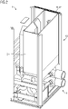
- the figure 1 shows a control cabinet 1 in a three-dimensional representation.
- the switch cabinet 1 includes a cooling device 4.
- the cooling device 4 is arranged in a lower area, ie in the vicinity of the bottom of the switch cabinet 1.
- FIG. In other words, the current-carrying components/components of the switch cabinet are arranged above the cooling device 4, so that if the pipes/lines shown leak, they are not affected.
- the cooling device 4 typically includes further cooling components.
- the cooling device 4 is symbolized by the two pipes shown, which are provided for supplying and discharging a cooling medium, in particular water.
- a hatched area 42 is shown, which indicates a space between the bars of the control cabinet 1 and on a rear wall 40 of the control cabinet 1.
- a heat exchanger in particular a finned tube, is arranged within the area 42 .
- the heat exchanger is thus also marked with the reference number 42 .
- the heat exchanger 42 is thus arranged in an installation space of the switch cabinet 1 which is unused in known switch cabinets. Furthermore, the heat exchanger 42 is connected to the main cooling circuit (symbolized by the pipes in the lower area) by an auxiliary cooling circuit and is thus supplied with cooling medium, in particular water.
- the connection ie the fluidic connection between the secondary cooling circuit and the main cooling circuit, can be made using a T-piece.
- the figure 2 shows a schematic three-dimensional representation of a switch cabinet 1 according to a second embodiment of the invention.
- the heat exchanger 42 is arranged in an upper area between the bars of the switch cabinet 1 .
- it is arranged on the rear wall and on the side between the bars. So that applies below figure 1 same said for those in the figure 2 illustrated second embodiment.
- the heat exchanger 42 could also be arranged on the rear wall 40 or a further heat exchanger could be provided, which is arranged on the rear wall 40 .
- the switch cabinet 1 preferably comprises two heat exchangers, with one of the heat exchangers being arranged on the rear wall 40 of the switch cabinet 1 and the other heat exchanger between the bars of the switch cabinet 1 in the hatched intermediate area 41.
Landscapes
- Engineering & Computer Science (AREA)
- Microelectronics & Electronic Packaging (AREA)
- Physics & Mathematics (AREA)
- Thermal Sciences (AREA)
- Aviation & Aerospace Engineering (AREA)
- Cooling Or The Like Of Electrical Apparatus (AREA)
- Patch Boards (AREA)
Priority Applications (5)
| Application Number | Priority Date | Filing Date | Title |
|---|---|---|---|
| EP21176257.0A EP4096377A1 (fr) | 2021-05-27 | 2021-05-27 | Armoire de commande pour l'électronique de puissance |
| EP22724427.4A EP4298875A1 (fr) | 2021-05-27 | 2022-04-19 | Armoire de distribution pour électronique d'alimentation |
| US18/564,272 US20240381592A1 (en) | 2021-05-27 | 2022-04-19 | Switchgear Cabinet for Power Electronics |
| CN202280032677.6A CN117296460A (zh) | 2021-05-27 | 2022-04-19 | 用于电力电子器件的开关柜 |
| PCT/EP2022/060217 WO2022248123A1 (fr) | 2021-05-27 | 2022-04-19 | Armoire de distribution pour électronique d'alimentation |
Applications Claiming Priority (1)
| Application Number | Priority Date | Filing Date | Title |
|---|---|---|---|
| EP21176257.0A EP4096377A1 (fr) | 2021-05-27 | 2021-05-27 | Armoire de commande pour l'électronique de puissance |
Publications (1)
| Publication Number | Publication Date |
|---|---|
| EP4096377A1 true EP4096377A1 (fr) | 2022-11-30 |
Family
ID=76159353
Family Applications (2)
| Application Number | Title | Priority Date | Filing Date |
|---|---|---|---|
| EP21176257.0A Withdrawn EP4096377A1 (fr) | 2021-05-27 | 2021-05-27 | Armoire de commande pour l'électronique de puissance |
| EP22724427.4A Pending EP4298875A1 (fr) | 2021-05-27 | 2022-04-19 | Armoire de distribution pour électronique d'alimentation |
Family Applications After (1)
| Application Number | Title | Priority Date | Filing Date |
|---|---|---|---|
| EP22724427.4A Pending EP4298875A1 (fr) | 2021-05-27 | 2022-04-19 | Armoire de distribution pour électronique d'alimentation |
Country Status (4)
| Country | Link |
|---|---|
| US (1) | US20240381592A1 (fr) |
| EP (2) | EP4096377A1 (fr) |
| CN (1) | CN117296460A (fr) |
| WO (1) | WO2022248123A1 (fr) |
Citations (3)
| Publication number | Priority date | Publication date | Assignee | Title |
|---|---|---|---|---|
| DE112007001694T5 (de) * | 2006-07-18 | 2009-06-10 | Liebert Corp., Columbus | Integrale hydraulische Schwenkverbindungselemente, Türgelenke und Verfahren und Systeme für deren Verwendung |
| US20140355201A1 (en) * | 2013-05-28 | 2014-12-04 | International Business Machines Corporation | Protecting devices against hot air backflow in a computer system rack having a rear door heat exchanger |
| EP3657921A1 (fr) * | 2018-11-26 | 2020-05-27 | Siemens Aktiengesellschaft | Dissipation thermique de l'armoire de distribution |
Family Cites Families (9)
| Publication number | Priority date | Publication date | Assignee | Title |
|---|---|---|---|---|
| DE19804904C1 (de) * | 1998-02-07 | 1999-11-11 | Loh Kg Rittal Werk | Schaltschrank mit Einrichtungen zum Kühlen der Innenraum-Warmluft |
| US6164369A (en) * | 1999-07-13 | 2000-12-26 | Lucent Technologies Inc. | Door mounted heat exchanger for outdoor equipment enclosure |
| DE10136457B4 (de) * | 2001-07-26 | 2005-02-03 | Rittal Gmbh & Co. Kg | Schaltschrank mit einer an der Frontseite angebrachten Schranktür und einer als Schranktür ausgebildeten Rückwand |
| JP4199018B2 (ja) * | 2003-02-14 | 2008-12-17 | 株式会社日立製作所 | ラックマウントサーバシステム |
| GB2493324A (en) * | 2011-05-27 | 2013-02-06 | Semper Holdings Ltd | Cooling System with heat-exchanger mounted within a server cabinet |
| KR101546450B1 (ko) * | 2013-12-26 | 2015-08-27 | 주식회사 효성 | 초고압 직류 송전시스템의 모듈냉각장치 |
| US20160120059A1 (en) * | 2014-10-27 | 2016-04-28 | Ebullient, Llc | Two-phase cooling system |
| US20180106500A1 (en) * | 2016-10-18 | 2018-04-19 | Trane International Inc. | Enhanced Tubular Heat Exchanger |
| US10912230B1 (en) * | 2019-09-20 | 2021-02-02 | Baidu Usa Llc | Hybrid multi-function door design for electronic racks |
-
2021
- 2021-05-27 EP EP21176257.0A patent/EP4096377A1/fr not_active Withdrawn
-
2022
- 2022-04-19 CN CN202280032677.6A patent/CN117296460A/zh active Pending
- 2022-04-19 EP EP22724427.4A patent/EP4298875A1/fr active Pending
- 2022-04-19 US US18/564,272 patent/US20240381592A1/en active Pending
- 2022-04-19 WO PCT/EP2022/060217 patent/WO2022248123A1/fr not_active Ceased
Patent Citations (3)
| Publication number | Priority date | Publication date | Assignee | Title |
|---|---|---|---|---|
| DE112007001694T5 (de) * | 2006-07-18 | 2009-06-10 | Liebert Corp., Columbus | Integrale hydraulische Schwenkverbindungselemente, Türgelenke und Verfahren und Systeme für deren Verwendung |
| US20140355201A1 (en) * | 2013-05-28 | 2014-12-04 | International Business Machines Corporation | Protecting devices against hot air backflow in a computer system rack having a rear door heat exchanger |
| EP3657921A1 (fr) * | 2018-11-26 | 2020-05-27 | Siemens Aktiengesellschaft | Dissipation thermique de l'armoire de distribution |
Also Published As
| Publication number | Publication date |
|---|---|
| CN117296460A (zh) | 2023-12-26 |
| EP4298875A1 (fr) | 2024-01-03 |
| WO2022248123A1 (fr) | 2022-12-01 |
| US20240381592A1 (en) | 2024-11-14 |
Similar Documents
| Publication | Publication Date | Title |
|---|---|---|
| DE112007000829T5 (de) | Kühler | |
| DE102014013958B4 (de) | Kühlanordnung für ein Kraftfahrzeugsteuergerät, Kraftfahrzeug und Kraftfahrzeugsteuergerät | |
| DE102018221951A1 (de) | Rohrförmige Kühlrippen und deren Anwendung | |
| DE102011107078A1 (de) | Heizkreis und elektronikanordnung | |
| DE102018216859A1 (de) | Kühlung mit Kühlrippen | |
| DE102018211666A1 (de) | Kühlanordnung | |
| DE102013222148A1 (de) | Kälteplatte für die Verwendung in einem Elektro- oder Hybridfahrzeug | |
| DE102020105925A1 (de) | Kühlungsanordnung für ein Kraftfahrzeug | |
| EP1469711A2 (fr) | Boítier avec refroidisseur pour des appareils électroniques de commande dans une automobile en particulier | |
| DE102021109740A1 (de) | Kühlsystem mit Zentralventileinrichtung für ein Elektrofahrzeug und Elektrofahrzeug mit einem solchen Kühlsystem | |
| WO2023179963A1 (fr) | Dispositif de charge inductif stationnaire | |
| DE19926007B4 (de) | Gehäuseeinheit | |
| DE112023003185T5 (de) | Immersionskühlungsvorrichtung | |
| DE102022115995A1 (de) | Vorrichtung mit einem Pulswechselrichter | |
| EP4298875A1 (fr) | Armoire de distribution pour électronique d'alimentation | |
| DE102018003173A1 (de) | Speichereinrichtung zum Speichern von elektrischer Energie für ein Kraftfahrzeug, insbesondere für einen Kraftwagen | |
| WO2018069174A1 (fr) | Système comportant un support et une électronique et procédé de fabrication d'un support | |
| DE19854465C1 (de) | Flüssigkeitsgekühlter Generator | |
| DE112022001138T5 (de) | Leistungsumwandlungsvorrichtung | |
| EP4052549A1 (fr) | Dispositif de refroidissement pour refroidir une pluralité de composants électroniques émetteurs de chaleur disposés sur un circuit imprimé, et système comprenant le dispositif de refroidissement | |
| WO2021259555A1 (fr) | Géométrie de refroidissement pour électronique de puissance | |
| EP3659892B1 (fr) | Dispositif de dissipation de chaleur pour véhicule ferroviaire et véhicule ferroviaire | |
| DE102021204695A1 (de) | Gehäuse zur Aufnahme von Batteriezellen und elektronischen Komponenten | |
| DE102021202091A1 (de) | Mehrlagige Bremswiderstandvorrichtung für ein Fahrzeug | |
| DE102024115734B3 (de) | Gekühlte Stromschiene und Ladesystem |
Legal Events
| Date | Code | Title | Description |
|---|---|---|---|
| PUAI | Public reference made under article 153(3) epc to a published international application that has entered the european phase |
Free format text: ORIGINAL CODE: 0009012 |
|
| STAA | Information on the status of an ep patent application or granted ep patent |
Free format text: STATUS: THE APPLICATION HAS BEEN PUBLISHED |
|
| AK | Designated contracting states |
Kind code of ref document: A1 Designated state(s): AL AT BE BG CH CY CZ DE DK EE ES FI FR GB GR HR HU IE IS IT LI LT LU LV MC MK MT NL NO PL PT RO RS SE SI SK SM TR |
|
| STAA | Information on the status of an ep patent application or granted ep patent |
Free format text: STATUS: THE APPLICATION IS DEEMED TO BE WITHDRAWN |
|
| 18D | Application deemed to be withdrawn |
Effective date: 20230531 |