EP4096839B1 - Dispositif d'application de revêtement sans fil à écartement variable - Google Patents
Dispositif d'application de revêtement sans fil à écartement variable Download PDFInfo
- Publication number
- EP4096839B1 EP4096839B1 EP21704315.7A EP21704315A EP4096839B1 EP 4096839 B1 EP4096839 B1 EP 4096839B1 EP 21704315 A EP21704315 A EP 21704315A EP 4096839 B1 EP4096839 B1 EP 4096839B1
- Authority
- EP
- European Patent Office
- Prior art keywords
- film
- rollers
- gap
- pair
- arms
- Prior art date
- Legal status (The legal status is an assumption and is not a legal conclusion. Google has not performed a legal analysis and makes no representation as to the accuracy of the status listed.)
- Active
Links
Images





Classifications
-
- B—PERFORMING OPERATIONS; TRANSPORTING
- B05—SPRAYING OR ATOMISING IN GENERAL; APPLYING FLUENT MATERIALS TO SURFACES, IN GENERAL
- B05C—APPARATUS FOR APPLYING FLUENT MATERIALS TO SURFACES, IN GENERAL
- B05C11/00—Component parts, details or accessories not specifically provided for in groups B05C1/00 - B05C9/00
- B05C11/02—Apparatus for spreading or distributing liquids or other fluent materials already applied to a surface ; Controlling means therefor; Control of the thickness of a coating by spreading or distributing liquids or other fluent materials already applied to the coated surface
- B05C11/023—Apparatus for spreading or distributing liquids or other fluent materials already applied to a surface
- B05C11/028—Apparatus for spreading or distributing liquids or other fluent materials already applied to a surface with a body having a large flat spreading or distributing surface
-
- B—PERFORMING OPERATIONS; TRANSPORTING
- B05—SPRAYING OR ATOMISING IN GENERAL; APPLYING FLUENT MATERIALS TO SURFACES, IN GENERAL
- B05C—APPARATUS FOR APPLYING FLUENT MATERIALS TO SURFACES, IN GENERAL
- B05C1/00—Apparatus in which liquid or other fluent material is applied to the surface of the work by contact with a member carrying the liquid or other fluent material, e.g. a porous member loaded with a liquid to be applied as a coating
- B05C1/04—Apparatus in which liquid or other fluent material is applied to the surface of the work by contact with a member carrying the liquid or other fluent material, e.g. a porous member loaded with a liquid to be applied as a coating for applying liquid or other fluent material to work of indefinite length
- B05C1/14—Apparatus in which liquid or other fluent material is applied to the surface of the work by contact with a member carrying the liquid or other fluent material, e.g. a porous member loaded with a liquid to be applied as a coating for applying liquid or other fluent material to work of indefinite length using a travelling band
-
- B—PERFORMING OPERATIONS; TRANSPORTING
- B05—SPRAYING OR ATOMISING IN GENERAL; APPLYING FLUENT MATERIALS TO SURFACES, IN GENERAL
- B05C—APPARATUS FOR APPLYING FLUENT MATERIALS TO SURFACES, IN GENERAL
- B05C11/00—Component parts, details or accessories not specifically provided for in groups B05C1/00 - B05C9/00
- B05C11/02—Apparatus for spreading or distributing liquids or other fluent materials already applied to a surface ; Controlling means therefor; Control of the thickness of a coating by spreading or distributing liquids or other fluent materials already applied to the coated surface
- B05C11/06—Apparatus for spreading or distributing liquids or other fluent materials already applied to a surface ; Controlling means therefor; Control of the thickness of a coating by spreading or distributing liquids or other fluent materials already applied to the coated surface with a blast of gas or vapour
-
- B—PERFORMING OPERATIONS; TRANSPORTING
- B05—SPRAYING OR ATOMISING IN GENERAL; APPLYING FLUENT MATERIALS TO SURFACES, IN GENERAL
- B05C—APPARATUS FOR APPLYING FLUENT MATERIALS TO SURFACES, IN GENERAL
- B05C1/00—Apparatus in which liquid or other fluent material is applied to the surface of the work by contact with a member carrying the liquid or other fluent material, e.g. a porous member loaded with a liquid to be applied as a coating
- B05C1/04—Apparatus in which liquid or other fluent material is applied to the surface of the work by contact with a member carrying the liquid or other fluent material, e.g. a porous member loaded with a liquid to be applied as a coating for applying liquid or other fluent material to work of indefinite length
- B05C1/08—Apparatus in which liquid or other fluent material is applied to the surface of the work by contact with a member carrying the liquid or other fluent material, e.g. a porous member loaded with a liquid to be applied as a coating for applying liquid or other fluent material to work of indefinite length using a roller or other rotating member which contacts the work along a generating line
- B05C1/0826—Apparatus in which liquid or other fluent material is applied to the surface of the work by contact with a member carrying the liquid or other fluent material, e.g. a porous member loaded with a liquid to be applied as a coating for applying liquid or other fluent material to work of indefinite length using a roller or other rotating member which contacts the work along a generating line the work being a web or sheets
- B05C1/083—Apparatus in which liquid or other fluent material is applied to the surface of the work by contact with a member carrying the liquid or other fluent material, e.g. a porous member loaded with a liquid to be applied as a coating for applying liquid or other fluent material to work of indefinite length using a roller or other rotating member which contacts the work along a generating line the work being a web or sheets being passed between the coating roller and one or more backing rollers
-
- B—PERFORMING OPERATIONS; TRANSPORTING
- B05—SPRAYING OR ATOMISING IN GENERAL; APPLYING FLUENT MATERIALS TO SURFACES, IN GENERAL
- B05C—APPARATUS FOR APPLYING FLUENT MATERIALS TO SURFACES, IN GENERAL
- B05C1/00—Apparatus in which liquid or other fluent material is applied to the surface of the work by contact with a member carrying the liquid or other fluent material, e.g. a porous member loaded with a liquid to be applied as a coating
- B05C1/04—Apparatus in which liquid or other fluent material is applied to the surface of the work by contact with a member carrying the liquid or other fluent material, e.g. a porous member loaded with a liquid to be applied as a coating for applying liquid or other fluent material to work of indefinite length
- B05C1/08—Apparatus in which liquid or other fluent material is applied to the surface of the work by contact with a member carrying the liquid or other fluent material, e.g. a porous member loaded with a liquid to be applied as a coating for applying liquid or other fluent material to work of indefinite length using a roller or other rotating member which contacts the work along a generating line
- B05C1/0873—Controlling means responsive to conditions of the liquid or other fluent material, of the ambient medium, of the roller or of the work
- B05C1/0882—Controlling means responsive to conditions of the liquid or other fluent material, of the ambient medium, of the roller or of the work responsive to the distance between two rollers, e.g. between the coating roller and a backing roller
Definitions
- the present invention relates to the formation of thin-film coatings using flowable substances and, more specifically, to facilities for obtaining thin films or coatings with a controlled variable gap.
- One wet film applicator known from the prior art comprises a pair of wedge-shaped elements, which are parallel to each other and bear a transverse plane blade that forms the coating.
- a gap between the bottom edge of the blade and a base plane (substrate) determines the thickness of the applied coating. The thickness of this gap is varied when the blade is moved along the wedge-shaped elements. Once the required gap thickness is set, the mutual arrangement of parts in the device is fixed. The blade is oriented perpendicularly to the direction of application and forms a film of desired thickness when the applicator is moved relative to the substrate surface.
- This device is quite universal and provides a level of accuracy that is sufficient for the formation of conventional paint, lacquer, and other wet film coatings. The problem with this technique is that during the clamping of the mechanism, the tightening screws directly press against the blade, which imparts a twisting motion to the blade, and that, in turn, reduces the accuracy and quality of the thin film.
- wet solutions can be applied using a drawing plate or a wiper (squeegee), which can be of a blade (sheet) or cylinder type.
- squeegee a wiper
- these devices do not ensure the formation of highly anisotropic films with reproducible characteristics, and this method of film formation requires prolonged preliminary work for determining the optimum application conditions for every batch of initial raw materials.
- Patents depicting various devices of the prior art include U.S. Pat. Nos. 4,869,200 , 6,174,394 , and 8,028,647 .
- DE 10 2008 054948 describes a device that comprises two rotatable transfer elements or rotatable endless bands that are associated to a coating aggregate.
- the transfer element transfers a coating medium applied with the coating aggregate on its surface in a press gap at the relevant side of fiber material web.
- the transfer element is associated to an insulation element and/or to a heating element.
- the insulation element is arranged downstream in the rotation direction of the transfer element equipped with the coating aggregate and/or the heating element.
- the device comprises two rotatable transfer elements or rotatable endless bands that are associated to a coating aggregate.
- the transfer element transfers a coating medium applied with the coating aggregate on its surface in a press gap at the relevant side of fiber material web.
- the transfer element is associated to an insulation element and/or to a heating element.
- the insulation element is arranged downstream in the- 2 -otateon direction of the transfer element equipped with the coating aggregate and/or the heating element.
- the heating element influences by coating medium externally applied on the surface of the transfer element.
- the heating element produces a processing temperature of 75-97°C and is infrared radiator that is electrically heated or heated by gas.
- the insulation element is arranged in an interval of 1-20 mm over the surface of the transfer element that partially overstretches the surface of the transfer element and passes into direct vicinity of the press gap.
- the insulation element is covered with a material, which has a low thermal conductivity.
- the transfer elements form a coating plant in the form of a glue press and/or film press for simultaneous coating of both sides or for individual coating of one of the sides of the fiber web with the coating medium.
- US 4 928 622 describes a machine for applying adhesive on one side of an elongate sheet material, and comprising an adhesive containing trough, an adhesive application roller and a driven pressure roller.
- the sheet material is being passed through the nip between said rollers and the width of the rollers surpasses the width of the sheet material.
- the contact surface of the pressure roller upon the sheet consists of an endless belt.
- the belt runs via at least one guide roller through a trough, containing rinsing fluid.
- the belt runs past at least one further guide roller, and past a brush roller which is mounted in the trough, adjacent the outer side of the endless belt loop.
- the brush roller is being driven in counter rotation to the direction of movement of the belt.
- the belt then runs back to the pressure roller, so that the section of the endless belt loop which has been driven past the rinsing fluid trough and the brush roller, returns to the nip free from adhesive.
- WO 99/67468 describes a method in film transfer coating in a film press, in which press the nip of the film press is formed out of two faces placed against each other and moving in the same direction so that said moving faces are pressed against each other in the nip.
- a coating agent or surface size is applied as a film onto at least one of the moving faces that form the film press nip and that are subjected to pressing, in which connection the coating agent or surface size is transferred in the nip between the moving faces onto the paper or board web running through the nip.
- the web is separated either directly from the nip or so that it follows one or the other of the moving faces.
- the web is separated from the nip so that, at least at one side of the web, the curve radius of the opening geometry is larger than 0.75 metre.
- a coating section is divided into a coating roller, which receives coating medium e.g. glue, paste, from a spray nozzle, and a flexible belt that receives the medium from the roller and applies the medium on a web.
- coating medium e.g. glue, paste
- Embodiments of the present invention are directed to the formation of a layer of material in a gap between two films.
- the presence of two films that can be moved relative to one another enables the creation of a uniform layer of material in-between the films while maintaining the possibility of easy cleaning just by rolling each one of the films when they are disengaged, thereby creating a completely new gap between them.
- Devices according to embodiments of the present invention are able to produce coatings at a high rate of application, with low consumption of raw materials and high-precision control over film thicknesses at very low cost.
- Systems configured in accordance with embodiments of the present invention find particular application in situations where film quality is of great importance.
- An important example of this kind of application is the family of laser enhanced jetting applications (for example, see U.S. Pat. No. 10,144,034 and U.S. Pat. No. 10,099,422 ).
- a highly uniform layer of material is needed in order to create a stable and reproducible jetting.
- Zenou et al. in U.S. Pat. No. 10,603,684 using a pair of films with a wire between them to control the gap width and thereby the material layer thickness.
- the present invention introduces yet another approach where the gap is maintained without the wire being present.
- inventions of the present invention provide for coating of a thin film with a desired material at a desired thickness.
- the material can be a viscous material in the form of a liquid or a paste, or a low viscosity material. It may be an adhesive or a metal or ceramic paste or any polymeric solution.
- the coating occurs in a gap between two rollers, it is disclosed but not claimed that it is also possible to create a coating with a flat (planar) substrate at one side of the gap.
- the roller(s) used to create/maintain the gap may be metallic, ceramic, or rubber rollers, such as polyurethane rubber rollers or others that will create a soft contact.
- the rollers may be free rollers or fixed ones.
- the width of the gap between the rollers, or between a roller and a planar substrate determines the thickness of the material layer directly or via some correlation. It is also possible to control the gap using a pressure control using the same mechanical structure.
- the film to be coated passes over one roller and a second film passes over a second roller opposite the first.
- This second film can be advanced along with the first to remove any residue from previous coating operations, or to recover unused material, or for other purposes.
- Using such a second film enables coating of multiple materials one after the other without any contamination, creating a very powerful tool for printing different materials in consecutive order.
- Air knives may be provided near the gap to create an air flow that aids in preventing the free flow of low viscosity materials outside the bounds of the film during coating.
- the material forms a layer on the film with a thickness equal to the distance between the two films across the gap.
- the roller opposite that of the film to be/being coated is maintained in position by two or more parallel springs.
- Two linear actuators (which may be in parallel with the springs) are used to move the second roller away from the first via two arms, thus widening the gap.
- a second pair (or other number) of springs arranged in parallel force the arms away from the second roller to avoid backlash when the linear actuators begin to pull the second roller away from the first.
- a linear encoder may be mounted on each side of the system to measure the position of each arm.
- the zero position of the system may be set as the position at which motion is first detected by the linear encoders. If the zero position corresponds to the rollers touching one another (or nearly so) the width of the gap is then determined by the amount of motion the linear encoders measure after this point.
- the start movement point may also be determined by force using pressure actuators.
- the system may be equipped with optical, mechanical, or electrical, limit switches, which serve to identify when the arms have reached their home positions (which may correspond to a zero gap width, a fully open gap width, or some other gap width in-between these two).
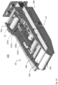
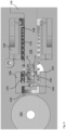
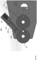
- a wire-less variable gap width system 100 configured in accordance with an embodiment of the present invention includes a frame 10 that supports a spool 12 and a take up reel 14 between sides 16a, 16b of the frame.
- a film 114 that is carried on spool 12 is passed over one roller 104 of a pair of rollers 102, 104, that are supported longitudinally adjacent one another at one end of frame 10 and is collected on take up reel 14.
- rollers 102 and 104 may be supported by pins about which they are free to rotate within frame 10. Alternatively, rollers 102 and 104 may be fixed about such pins, with films 112, 114 sliding over the rollers, but the rollers themselves not moving.
- Film 112 which is to be coated with a material passes about roller 102, between roller 102 and 104, adjacent film 114 along a lateral dimension of frame 10 at which rollers 102 and 104 are closest together. Coating of the film 112 occurs in the gap 20 between rollers 102 and 104, or more precisely between films 112 and 114, which are disposed about the outer surfaces to the two rollers.
- the material 110 to be coated on film 112 is deposited at a point above gap 20 (or, more precisely, upstream in a direction of film 112 travel from gap 20) and the motion of film 112 about roller 102 draws a layer 18 of material 110 onto the outer surface of film 112, with the width of gap 20 determining the thickness of the material layer 18.
- Film 114 can be advanced about roller 104 as film 112 is advanced about roller 102 in order to remove any residual material 110 from the area of gap 20, e.g., residue due to previous coating operations, to recover unused portions of material 110, or for other purposes (e.g., in connection with a change of materials 110).
- the material 110 to be coated on film 112 may be a viscous material such as a liquid, a paste, or an adhesive, or it may be a low viscosity material such as a polymeric solution.
- the material 110 may be changed between two consecutive coating procedures, with the gap 20 being enlarged during the coating of the second material so as not to displace a previously coated material layer on film 112.
- the various rollers and spools described herein may be made of metal, ceramic, plastic, rubber, or a combination of such materials and may be coated so as to allow the films 112, 114 to pass freely thereover.
- the material 110 may deposited near gap 20 from a syringe or other reservoir in which the material 110 is maintained.
- a syringe or other reservoir may be kept in a controlled environment in which pressure, temperature, and/or other environmental conditions are maintained according to the needs of material 110.
- the material 110 is deposited upstream of gap 20 to be coated on film 112 (or another substrate), which then passes through gap 20 formed by the pair of cylindrical rollers 102, 104. After passing through the gap 20, a uniform layer 18 of the material 110 will be present on film 112 and the coated film can be provided to further stations for deposition/dispensing of the material or for other purposes.
- the coated portion of film 112 can be returned to a position upstream of gap 20 (e.g., in a loop or by linear translation) for recoating with a uniform layer of a second material or to fill in any spaces in layer 18 from the first coating.
- film 112 can be translated bidirectionally in a controlled manner, so that it can be repositioned while opening the gap 20 between rollers 102, 104, allowing for recoating the same area of film 112 with material 110 (or another material) without contamination to the rollers and reducing or eliminating the amount of film 112 consumed during the coating process.
- Film 112 may be a transparent film or other substrate, with or without a metal (or other) backing.
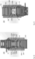
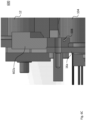
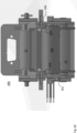
- Figures 1A-1C and 2 illustrate arms 106a, 106b inside of sides 16a, 16b within frame 10. While two, parallel arms 106a, 106b are preferred, in some embodiments more than two arms may be present. In some disclosed but not claimed embodiments only a single arm may be present. In the following description, reference is made to a single arm 106 and is associated components, however, it should be appreciated that the same description applies equally to a second arm and/or additional arms and its/their associated components, where present.
- arm 106 biases (through springs and an associated bearing, as discussed below) roller 104 along its length so as to maintain consistency in width across the lateral dimension of gap 20.
- a guide assembly 130 At one end of arm 106 is a guide assembly 130 through which a tapered portion 132 of arm 106 passes. Tapered portion 132 of arm 106 terminates in a notched end 134 having two parallel outer edges 136 and an inner spring anchor 138 in the form of a detent that does not extend the entire length of a recess 140 formed by the two parallel outer edges 136 in the notched end 134.
- An H-shaped bracket 108 receives the notched end 134 of arm 106 within recess 142 formed in one side of the bracket.
- the opposite side of bracket 108 abuts a bearing 144 which acts as an interface between bracket 108 and roller 104.
- Bearing 108 may be made of metal, ceramic, plastic, rubber, or a combination of such materials and may be coated so as to allow roller 104 to turn freely about its axis.
- a spring 118 is helically coiled about an outer perimeter of tapered portion 132 of arm 106 within recess 142 and guide assembly 130 and is compressed between a detent 148 of guide assembly 130 and a cross member 146 of H-shaped bracket 108.
- a second spring 116 is located within recess 140 in the notched end 134 of arm 106 and is helically coiled about inner spring anchor 138.
- Spring 116 biases arm 106 against H-shaped bracket 108 and, in turn, roller 104, and is compressed between an inner surface of recess 140 in notched end 134 and cross member 146 of H-shaped bracket 108. Spring 116 thus forces arm 106 away from roller 104 to avoid backlash when the linear actuator begins to move arm 106.
- Springs 116 and 118 have counterparts for the arm on the opposite side of frame 10.
- linear actuators 124a, 124b are arranged to move respective arms 106a, 106b longitudinally within frame 10. Moving arms 106a, 106b in this fashion will translate roller 104 within frame 10, thereby adjusting the width of gap 20 between rollers 102, 104. Operation of the linear actuators 124a, 124b is achieved, in one embodiment, using a processor-based controller (not shown).
- processor-based controller upon or with which the methods of the present invention may be practiced will typically include a processor communicably coupled to a bus or other communication mechanism for communicating information; a main memory, such as a RAM or other dynamic storage device, coupled to the bus for storing information and instructions to be executed by the processor and for storing temporary variables or other intermediate information during execution of instructions to be executed by the processor; and a ROM or other static storage device coupled to the bus for storing static information and instructions for the processor.
- a storage device such as a hard disk or solid-state drive, may also be included and coupled to the bus for storing information and instructions.
- the subject controller may, in some instances, include a display coupled to the bus for displaying information to a user.
- an input device including alphanumeric and/or other keys, may also be coupled to the bus for communicating information and command selections to the processor.
- Other types of user input devices such as cursor control devices may also be included and coupled to the bus for communicating direction information and command selections to the processor and for controlling cursor movement on the display.
- the controller may also include a communication interface coupled to the processor, which provides for two-way, wired and/or wireless data communication to/from the controller, for example, via a local area network (LAN).
- the communication interface sends and receives electrical, electromagnetic, or optical signals which carry digital data streams representing various types of information.
- the controller may be networked with a remote unit (not shown) to provide data communication to a host computer or other equipment operated by a user. The controller can thus exchange messages and data with the remote unit, including diagnostic information to assist in troubleshooting errors, if needed.
- Such a controller may be programmed to operate linear actuators 124a, 124b to move the arms 106a, 106b to achieve a desired gap width 20 for coating a film 114 with a film 18 of material 110 of desired thickness.
- the controller also may be programmed to advance film 112 and/or film 114 as needed for such a coating process.
- the linear actuators 124a, 124b may employ piezo translators that include a piezo ceramic that expands in a defined direction upon application of an electric current (e.g., under the control of the controller).
- the ceramic may be orientated so that when it expands (at the application of a current under the control of the controller), the arm connected to the actuator is displaced along a single axis (e.g., the longitudinal dimension), along the direction of the expansion of the crystal.
- a number of piezo translators may be used per actuator and the various piezo translators may be energized at the same time (or nearly so) so that their actions are coordinated with one another.
- the piezo translators may be arranged so that they impart longitudinal motion to the arms in the same direction and the translation distance may be proportional to the magnitude of the current applied to the piezo translators.
- the piezo translator(s) employed in embodiments of the present invention may be any of longitudinal piezo actuators, in which an electric field in the ceramic is applied parallel to the direction of its polarization; piezoelectric shear actuators, in which the electric field in the ceramic is applied orthogonally to the direction of its polarization; or tube actuators, which are radially polarized and have electrodes are applied to an outer surfaces of the ceramic so that the field parallel to its polarization also runs in a radial direction.
- the linear actuators 124a, 124b may employ lead screws that are advanced or retracted according to control signals from the controller to move arms 106a, 106b in the longitudinal dimension.
- linear actuators 124a, 124b may employ worm drives that are activated according to control signals from the controller to move arms 106a, 106b in the longitudinal dimension.
- actuator herein is intended to encompass various alternative means for displacing the arms in the longitudinal dimension.
- springs 118 act to bias roller 104 towards roller 102, thereby maintaining a constant gap width across the longitudinal dimension of the rollers.
- Respective springs 116 act to bias the arms 106a, 106b away from the roller 104 to avoid backlash when the associated linear actuator 124a, 124b begins to pull roller 104 away from roller 102, widening gap 20.
- a linear encoder 120 is mounted on the frame 10 to measure the position of each respective arm 106a, 106b. When the linear actuators 124a, 124b move roller 104, a "zero" position of the system may be set as the position at which such motion is first detected by the linear encoder 120. The width of the gap 20 is then determined by the amount of motion the linear encoder 120 measures after this point.
- System 100 is also equipped with two optical, or other, limit switches 122a, 122b.
- the limit switches 122a, 122b serve to identify when each respective arm 106a, 106b has reached its home position.
- the home position may define a minimum, maximum, or other gap width between rollers 102, 104.
- coating of a layer 18 of material 110 onto film 112 occurs in the gap 20 between rollers 102 and 104.
- the width of this gap 20 determines the thickness of the material layer 18 and is set by positioning roller 104 a desired distance from roller 102 using linear actuators 124a, 124b.
- Linear actuators 124a, 124b adjust the position of arms 106a, 106b, which in turn set the position of roller 104 (e.g., with respect to roller 102) through the biasing of respective springs 118, one per arm and parallel to one another.
- film 112 is passed over roller 102 and film 114 is passed over roller 104 opposite film 112 (e.g., to remove any material residue from a previous coating, to recover unused material 110 or for other purposes).
- film 112 is advanced through gap 20 between the rollers 102, 104, the material 110 forms a layer 18 with thickness equal to the gap width on film 112.
- the layer of material that is coated onto the film 112 may be a mixture of two or more separate materials.
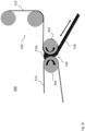
- Figures 5A-5C illustrate one use of a well-defined gap 520 between rollers 502, 504 of a wire-less variable gap width system 500 configured in accordance with an embodiment of the present invention for such mixing of multiple materials 510a, 510b when coating a film 512 or other substrate.
- the ability to use a gap in such a system for mixing two or more materials just before printing may be of particular importance when the various materials react with one another and dispensing them together on a film from a common dispenser (e.g., a syringe) may end up obstructing or otherwise impairing the operation of the dispenser.
- each material is distributed onto the film from its own dispenser and the reaction between the materials (if any) takes place only on the film just before printing.
- a technique may be employed in other gap-based coating systems that do not utilize other aspects of the above-described wire-less variable gap width system, hence, the provision of a gap-based mixing arrangement should not be construed as being limited to such systems.
- system 500 contains two films 512, 514 that each roll over a respective one of a pair of rollers 502, 504 to create a known gap 520 between them.
- the films and rollers of the system may be made of any of the materials for such items described herein.
- Film 512 on which a layer of material will be coated is dispensed by an arrangement 550 which, in this example, has a pair of feeder rollers, but this is only for illustration and the details of the dispensing arrangement are not critical to the present invention.
- Film 514 can be advanced about roller 504 as film 512 is advanced about roller 502 in order to remove any residual amounts of the mixture 510c from the area of gap 520, e.g., to prevent blockage of the gap.
- the materials 510a, 510b used to form the mixture 510c may be any of those discussed above and one or more of the materials may be replenished and/or changed between consecutive coating procedures, with the gap 520 being enlarged during such second coatings so as not to displace a previously coated material layer 518 on film 512.
- the direction of travel of the coated film may be controlled so that the coated film is drawn back through gap 520 with the layer 518 thereon and then passed through gap 520 in the original direction so as to ensure a thorough mixing of the materials that make up layer 518.
- Such a process may be repeated multiple times to obtain an optimum level of such mixing and to help ensure a uniform layer thickness on film 512.
- bidirectional translation of the film 512 through gap 520 may be undertaken while reducing the width of gap 520, e.g., using biased arms controlled by linear actuators to position roller 504 relative to roller 502 as discussed above, so as to produce a layer 518 of a desired thickness.
- FIG. 6A-6D , 7 , and 8 a further embodiment of a wire-less variable gap width system 600 configured in accordance with yet another embodiment of the present invention is illustrated.
- components that are the same as those discussed above with respect to wire-less variable gap width system 100 are given similar reference numerals and will not be described further, except in connection with the air knives 602a, 602b included in wire-less variable gap width system 600 for removal of material.
- the air knives 602a, 602b included in wire-less variable gap width system 600 for removal of material.
- the gap 20 when coating a film 112, it is possible that the gap 20 will become contaminated by unused material 110. Some of the contaminants can be removed using a second film 114, and with relatively viscous materials that technique works well.
- air knives 602a, 602b may be used. That is, air propelled by air knives 602a, 602b may act as a physical impediment to the flowing of the low viscosity material outside the bounds of the film 112, where the material may contaminate the rollers 102, 104, e.g., on their sides opposite gap 20.
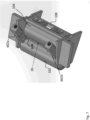
- Figure 7 further illustrates the provision of air knives 602a, 602b near a gap 20 between rollers 102, 104 of a wire-less variable gap width system configured in accordance with an embodiment of the present invention
- Figure 8 illustrates a cut-away view of a pair of air knives 602a, 602b near such a gap 20.
- Each air knife 602a, 602b creates an air flow at an angle of 0-180 degrees from a respective side of the propagating material film 112, and preferably at an angle of 70-110 degrees from such side.
- the angle of the air flow may be directed from 0 to 180 degrees from a respective side of the film, either by rotating the air knife with respect to frame 10 and/or by design of the air flow channel within the air knife, but it has become apparent that an angle of 70-90 degrees will be most effective in preventing the free flow of low viscosity materials.
- Air knives 602a, 602b each include a threaded coupling 604 to which an air hose may be attached.
- threaded coupling 604 may be a check valve to allow airflow only in one direction.
- threaded coupling 604 may be a Schrader valve or a Presta valve, either of which may have an associated valve stem 606 to direct air from an air hose or other air supply means to an outlet 608 that is directed towards the area where the edge of the film 112 will pass near gap 20.
- the air knives may be used in conjunction with any of the embodiments described herein.
- the present invention provides, in various embodiments, systems and methods that enable coating of a thin film with a viscous or other material at a desired thickness at low cost and in a high quality.
Landscapes
- Coating Apparatus (AREA)
- Application Of Or Painting With Fluid Materials (AREA)
Claims (11)
- Système (100, 500, 600), comprenant deux films (112, 114, 512, 514) qui sont agencés pour se déplacer de manière adjacente l'un par rapport à l'autre sur des surfaces externes de rouleaux respectifs (102, 104, 502, 504) positionnés l'un par rapport à l'autre pour définir un espace (20, 520) entre les films (112, 114, 512, 514) qui, à son tour, définit une épaisseur pour une couche (18, 518) d'un matériau à appliquer en revêtement sur l'un des films (112, 114, 512, 514), caractérisé en ce qu'un premier des rouleaux (104, 504) est positionné par rapport à un second des rouleaux (102, 502) par un palier (144) sollicité par une première paire de ressorts parallèles (118) et est ajustable en position par rapport au second des rouleaux (102, 502) par une paire d'actionneurs linéaires (124a, 124b) configurés pour déplacer en translation des bras respectifs (106a, 106b) qui supportent la première paire de ressorts parallèles (118).
- Système (100, 500, 600) selon la revendication 1, comprenant en outre une seconde paire de ressorts parallèles (116) agencés pour solliciter les bras (106a, 106b) à l'écart du premier des rouleaux (104, 504).
- Système (100, 500, 600) selon la revendication 1, comprenant en outre une paire de codeurs linéaires (120) montés pour mesurer des positions de chaque bras respectif (106a, 106b), dans lequel une position initiale pour le système (100, 500, 600) est définie comme une position dans laquelle un mouvement est d'abord détecté par la paire de codeurs linéaires (120) lorsque la paire d'actionneurs linéaires (124a, 124b) déplace les bras (106a, 106b) qui ajustent la position du premier des rouleaux (104, 504).
- Système (100, 500, 600) selon la revendication 3, dans lequel une largeur de l'intervalle (20, 520) est déterminée comme une distance que la paire de codeurs linéaires (120) mesure par le mouvement des bras (106a, 106b) .
- Système (100, 500, 600) selon la revendication 3, comprenant en outre un commutateur de fin de course (122a, 122b) configuré pour identifier une position initiale des bras (106a, 106b), dans lequel le commutateur de fin de course (122a, 122b) est un commutateur de fin de course optique, un commutateur de fin de course électrique ou un commutateur de fin de course mécanique.
- Système (100, 500, 600) selon l'une quelconque des revendications précédentes, dans lequel le matériau est l'un d'un matériau visqueux, d'un liquide, d'une pâte, d'un adhésif, d'un matériau à faible viscosité ou d'une solution polymère.
- Système (100, 500, 600) selon l'une quelconque des revendications précédentes, dans lequel les rouleaux (102, 104, 502, 504) sont en métal, en céramique, en plastique ou en caoutchouc.
- Procédé, comprenant les étapes consistant à revêtir un premier film (114, 514) avec une couche (18, 518) d'un matériau, déplacer le premier film (114, 514) et un second film (112, 512) adjacents l'un par rapport à l'autre sur des rouleaux respectifs (102, 104, 502, 504) à travers un espace (20, 520) entre les rouleaux (102, 104, 502, 504), l'espace (20, 520) définissant une épaisseur de la couche (18, 518) du matériau sur le premier film (114, 514), de telle sorte qu'une quantité du matériau déposé en amont en termes de direction de déplacement des premier et second films (112, 114, 512, 514) à partir de l'espace (20, 520) est attirée à travers l'espace (20, 520), caractérisé par le positionnement d'un premier des rouleaux respectifs (104, 504) à l'opposé d'un second des rouleaux respectifs (102, 502) en sollicitant un palier (144) supportant le premier des rouleaux respectifs (104, 504) par une première paire de ressorts parallèles (118), et l'élargissement de l'espace (20, 520) entre les rouleaux (102, 104, 502, 504) en déplaçant le premier des rouleaux respectifs (104, 504) par rapport au second des rouleaux respectifs (102, 502) à l'aide d'une paire d'actionneurs linéaires (124a, 124b) couplés pour déplacer en translation des bras respectifs (106a, 106b) qui supportent la première paire de ressorts parallèles (118), dans lequel le premier film (114, 514) passe sur le premier des rouleaux respectifs (104, 504) et le second film (112, 512) passe sur le second des rouleaux respectifs (102, 502) à l'opposé du premier film (114, 514).
- Procédé selon la revendication 8, dans lequel le second film (112, 512) est avancé en même temps que le premier film (114, 514) pour éliminer tout résidu d'un revêtement précédent ou pour récupérer des quantités inutilisées du matériau.
- Procédé selon l'une quelconque des revendications 8 ou 9, comprenant en outre une sollicitation des bras (106a, 106b) à l'écart du premier des rouleaux respectifs (104, 504) par une seconde paire de ressorts (116) pour éviter un jeu lorsque la paire d'actionneurs linéaires (124a, 124b) déplace en translation les bras (106a, 106b).
- Procédé selon la revendication 10, comprenant en outre une mesure de positions des bras respectifs (106a, 106b) pendant le mouvement des bras (106a, 106b) en utilisant une paire de codeurs linéaires (120), une définition d'une position zéro en tant que position dans laquelle un mouvement est d'abord détecté par la paire de codeurs linéaires (120) lorsque la paire d'actionneurs linéaires (124a, 124b) déplace les bras (106a, 106b), et un utilisation d'un commutateur de fin de course (122a, 122b) pour identifier quand les bras (106a, 106b) ont atteint une position initiale.
Applications Claiming Priority (2)
| Application Number | Priority Date | Filing Date | Title |
|---|---|---|---|
| US202062704213P | 2020-04-28 | 2020-04-28 | |
| PCT/IB2021/050389 WO2021220064A1 (fr) | 2020-04-28 | 2021-01-19 | Dispositif d'application de revêtement sans fil à écartement variable |
Publications (3)
| Publication Number | Publication Date |
|---|---|
| EP4096839A1 EP4096839A1 (fr) | 2022-12-07 |
| EP4096839B1 true EP4096839B1 (fr) | 2023-11-08 |
| EP4096839C0 EP4096839C0 (fr) | 2023-11-08 |
Family
ID=74572820
Family Applications (1)
| Application Number | Title | Priority Date | Filing Date |
|---|---|---|---|
| EP21704315.7A Active EP4096839B1 (fr) | 2020-04-28 | 2021-01-19 | Dispositif d'application de revêtement sans fil à écartement variable |
Country Status (6)
| Country | Link |
|---|---|
| US (2) | US11478814B2 (fr) |
| EP (1) | EP4096839B1 (fr) |
| JP (1) | JP2023523723A (fr) |
| KR (1) | KR20230009362A (fr) |
| CN (1) | CN115362030B (fr) |
| WO (1) | WO2021220064A1 (fr) |
Families Citing this family (4)
| Publication number | Priority date | Publication date | Assignee | Title |
|---|---|---|---|---|
| US12420479B2 (en) | 2021-12-23 | 2025-09-23 | Reophotonics, Ltd. | Systems for printing viscous materials using laser assisted deposition |
| US12194488B2 (en) | 2022-08-23 | 2025-01-14 | Reophotonics, Ltd. | Coating system with an adjustable gap between two rollers |
| CN119305231B (zh) * | 2024-10-22 | 2025-11-21 | 福建思嘉环保材料科技有限公司 | 一种柔性夹网水池材料及其制备方法 |
| US20260131387A1 (en) * | 2024-11-11 | 2026-05-14 | The Boeing Company | Systems and methods for determining bore characteristics of a hole |
Family Cites Families (18)
| Publication number | Priority date | Publication date | Assignee | Title |
|---|---|---|---|---|
| US3595206A (en) * | 1968-06-24 | 1971-07-27 | Charles A Larimer | Adhesive-applying apparatus |
| SE463135B (sv) | 1988-02-12 | 1990-10-15 | Akerlund & Rausing Ab | Maskin foer paafoering av lim paa en sida av en materialbana |
| US4869200A (en) | 1988-06-20 | 1989-09-26 | Paul N. Gardner Company, Inc. | Adjustable wet film thickness applicator capable of forming films of uniform thickness and non-uniform thickness |
| RU2047643C1 (ru) | 1993-05-21 | 1995-11-10 | Хан Ир Гвон | Материал для поляризующих покрытий |
| FI104435B (fi) | 1998-06-23 | 2000-01-31 | Valmet Corp | Menetelmä filminsiirtopäällystyksessä ja menetelmän toteuttamiseen filmipuristin |
| WO2002095126A2 (fr) * | 2001-05-23 | 2002-11-28 | Voith Paper Patent Gmbh | Dispositif, procede et systeme destines a comprimer deux cylindres d'axes paralleles pouvant etre rapproches l'un de l'autre dans une installation de fabrication et/ou de traitement d'une bande de materiau |
| US6827783B2 (en) * | 2001-11-19 | 2004-12-07 | Murata Manufacturing Co., Ltd. | Paste application apparatus and method for applying paste |
| DE10318028A1 (de) | 2003-04-19 | 2004-11-04 | Voith Paper Patent Gmbh | Auftragswerk |
| DE10337594B4 (de) * | 2003-08-16 | 2006-03-23 | Siempelkamp Maschinen- Und Anlagenbau Gmbh & Co. Kg | Trennmittelauftragsvorrichtung |
| KR100775226B1 (ko) * | 2006-06-05 | 2007-11-12 | 주식회사 포스코 | 강판 용융도금 라인의 에어 나이프 |
| WO2008063631A2 (fr) | 2006-11-21 | 2008-05-29 | Collengin, Inc. | Ensemble applicateur de film liquide et système de cisaillement rectiligne incorporant cet ensemble |
| DE102008054948A1 (de) | 2008-12-19 | 2010-07-01 | Voith Patent Gmbh | Auftragsvorrichtung |
| US8297221B2 (en) * | 2010-06-22 | 2012-10-30 | Ortho-Clinical Diagnostics, Inc. | Apparatus for slot die setup and control during coating |
| EP2551024B1 (fr) * | 2011-07-29 | 2017-03-22 | 3M Innovative Properties Co. | Film multicouche doté d'au moins une couche mince et procédé continu de formation d'un tel film |
| US8393826B1 (en) * | 2011-08-31 | 2013-03-12 | Caterpillar Inc. | Apparatus for transferring linear loads |
| CN109641468B (zh) | 2016-07-17 | 2021-07-27 | Io技术集团公司 | 用于激光诱导的材料分配的套件和系统 |
| EP3796116B1 (fr) | 2016-09-15 | 2025-11-12 | IO Tech Group, Ltd. | Procédé et système de fabrication additive-ablative |
| CN116174254B (zh) | 2018-03-15 | 2025-11-11 | Io技术集团公司 | 多材料分配和涂覆系统 |
-
2021
- 2021-01-19 JP JP2022564022A patent/JP2023523723A/ja active Pending
- 2021-01-19 WO PCT/IB2021/050389 patent/WO2021220064A1/fr not_active Ceased
- 2021-01-19 US US17/248,301 patent/US11478814B2/en active Active
- 2021-01-19 EP EP21704315.7A patent/EP4096839B1/fr active Active
- 2021-01-19 KR KR1020227032782A patent/KR20230009362A/ko not_active Withdrawn
- 2021-01-19 CN CN202180025068.3A patent/CN115362030B/zh active Active
-
2022
- 2022-09-19 US US17/933,299 patent/US12059700B2/en active Active
Also Published As
| Publication number | Publication date |
|---|---|
| US20210331196A1 (en) | 2021-10-28 |
| US11478814B2 (en) | 2022-10-25 |
| JP2023523723A (ja) | 2023-06-07 |
| WO2021220064A1 (fr) | 2021-11-04 |
| CN115362030B (zh) | 2025-12-05 |
| CN115362030A (zh) | 2022-11-18 |
| KR20230009362A (ko) | 2023-01-17 |
| US20230012396A1 (en) | 2023-01-12 |
| US12059700B2 (en) | 2024-08-13 |
| EP4096839A1 (fr) | 2022-12-07 |
| EP4096839C0 (fr) | 2023-11-08 |
Similar Documents
| Publication | Publication Date | Title |
|---|---|---|
| US12059700B2 (en) | Method for operating a wire-less variable gap coater device | |
| US11440047B2 (en) | Dispensing unit and dispensing system | |
| CN100400290C (zh) | 液体涂布装置、记录装置 | |
| JPH02135175A (ja) | 移動ウェブその他の基体上へのホットメルトその他の粘性流動体をスクリーンプリンティング又は塗工する方法及びその装置 | |
| KR100251997B1 (ko) | 점성액을 재료 표면에 도포하기 위한 개량된 장치 및 방법 | |
| RU2343238C1 (ru) | Устройство для нанесения текучих сред на товарное полотно | |
| JPS63500707A (ja) | 帯状材料上への液体塗布装置 | |
| CN104226532A (zh) | 热熔胶涂抹设备及热熔胶的涂抹方法 | |
| CN1572481A (zh) | 将粘合剂连续地涂抹到带状物上的方法和粘合剂涂抹装置 | |
| JPH10328597A (ja) | 多孔性材料ウェブへの薄いコーティング塗料層の塗布装置 | |
| US4345543A (en) | Apparatus for forming a coating on a substrate | |
| KR100911635B1 (ko) | 편광 필름 제조 장치 | |
| US20050260020A1 (en) | Skiving device and methods of use | |
| US4363288A (en) | Device for applying a coating layer to a strip of continuously moving material | |
| JPS622991B2 (fr) | ||
| EP2025412B1 (fr) | Distributeur de liquide avec buse de contact montée sur ressort | |
| US7245346B2 (en) | Method of making an electronic display | |
| EP2846930B1 (fr) | Dispositif pour niveler et établir l'épaisseur d'une couche d'agent liquide étalée sur une matière | |
| JP5699370B2 (ja) | ドクターブレード装置 | |
| CN219210454U (zh) | 涂布机头和涂布装置 | |
| JPH04247259A (ja) | シート材に接着剤を塗布する装置 | |
| US12194488B2 (en) | Coating system with an adjustable gap between two rollers | |
| CA2288354C (fr) | Mecanisme de transfert de l'encre d'une presse a imprimer et utilisation de celui-ci | |
| RU2294828C2 (ru) | Устройство для распределения порошков на подложке в соответствии с заданным рисунком | |
| JP4619161B2 (ja) | 塗布装置 |
Legal Events
| Date | Code | Title | Description |
|---|---|---|---|
| STAA | Information on the status of an ep patent application or granted ep patent |
Free format text: STATUS: UNKNOWN |
|
| STAA | Information on the status of an ep patent application or granted ep patent |
Free format text: STATUS: THE INTERNATIONAL PUBLICATION HAS BEEN MADE |
|
| PUAI | Public reference made under article 153(3) epc to a published international application that has entered the european phase |
Free format text: ORIGINAL CODE: 0009012 |
|
| STAA | Information on the status of an ep patent application or granted ep patent |
Free format text: STATUS: REQUEST FOR EXAMINATION WAS MADE |
|
| 17P | Request for examination filed |
Effective date: 20220901 |
|
| AK | Designated contracting states |
Kind code of ref document: A1 Designated state(s): AL AT BE BG CH CY CZ DE DK EE ES FI FR GB GR HR HU IE IS IT LI LT LU LV MC MK MT NL NO PL PT RO RS SE SI SK SM TR |
|
| GRAP | Despatch of communication of intention to grant a patent |
Free format text: ORIGINAL CODE: EPIDOSNIGR1 |
|
| STAA | Information on the status of an ep patent application or granted ep patent |
Free format text: STATUS: GRANT OF PATENT IS INTENDED |
|
| INTG | Intention to grant announced |
Effective date: 20230317 |
|
| GRAJ | Information related to disapproval of communication of intention to grant by the applicant or resumption of examination proceedings by the epo deleted |
Free format text: ORIGINAL CODE: EPIDOSDIGR1 |
|
| STAA | Information on the status of an ep patent application or granted ep patent |
Free format text: STATUS: REQUEST FOR EXAMINATION WAS MADE |
|
| GRAP | Despatch of communication of intention to grant a patent |
Free format text: ORIGINAL CODE: EPIDOSNIGR1 |
|
| STAA | Information on the status of an ep patent application or granted ep patent |
Free format text: STATUS: GRANT OF PATENT IS INTENDED |
|
| INTC | Intention to grant announced (deleted) | ||
| INTG | Intention to grant announced |
Effective date: 20230607 |
|
| DAV | Request for validation of the european patent (deleted) | ||
| DAX | Request for extension of the european patent (deleted) | ||
| GRAS | Grant fee paid |
Free format text: ORIGINAL CODE: EPIDOSNIGR3 |
|
| GRAA | (expected) grant |
Free format text: ORIGINAL CODE: 0009210 |
|
| STAA | Information on the status of an ep patent application or granted ep patent |
Free format text: STATUS: THE PATENT HAS BEEN GRANTED |
|
| AK | Designated contracting states |
Kind code of ref document: B1 Designated state(s): AL AT BE BG CH CY CZ DE DK EE ES FI FR GB GR HR HU IE IS IT LI LT LU LV MC MK MT NL NO PL PT RO RS SE SI SK SM TR |
|
| REG | Reference to a national code |
Ref country code: GB Ref legal event code: FG4D |
|
| REG | Reference to a national code |
Ref country code: CH Ref legal event code: EP |
|
| REG | Reference to a national code |
Ref country code: DE Ref legal event code: R096 Ref document number: 602021006673 Country of ref document: DE |
|
| REG | Reference to a national code |
Ref country code: IE Ref legal event code: FG4D |
|
| U01 | Request for unitary effect filed |
Effective date: 20231115 |
|
| U07 | Unitary effect registered |
Designated state(s): AT BE BG DE DK EE FI FR IT LT LU LV MT NL PT SE SI Effective date: 20231122 |
|
| U20 | Renewal fee for the european patent with unitary effect paid |
Year of fee payment: 4 Effective date: 20240125 |
|
| PG25 | Lapsed in a contracting state [announced via postgrant information from national office to epo] |
Ref country code: GR Free format text: LAPSE BECAUSE OF FAILURE TO SUBMIT A TRANSLATION OF THE DESCRIPTION OR TO PAY THE FEE WITHIN THE PRESCRIBED TIME-LIMIT Effective date: 20240209 |
|
| PG25 | Lapsed in a contracting state [announced via postgrant information from national office to epo] |
Ref country code: IS Free format text: LAPSE BECAUSE OF FAILURE TO SUBMIT A TRANSLATION OF THE DESCRIPTION OR TO PAY THE FEE WITHIN THE PRESCRIBED TIME-LIMIT Effective date: 20240308 |
|
| PG25 | Lapsed in a contracting state [announced via postgrant information from national office to epo] |
Ref country code: ES Free format text: LAPSE BECAUSE OF FAILURE TO SUBMIT A TRANSLATION OF THE DESCRIPTION OR TO PAY THE FEE WITHIN THE PRESCRIBED TIME-LIMIT Effective date: 20231108 |
|
| PG25 | Lapsed in a contracting state [announced via postgrant information from national office to epo] |
Ref country code: IS Free format text: LAPSE BECAUSE OF FAILURE TO SUBMIT A TRANSLATION OF THE DESCRIPTION OR TO PAY THE FEE WITHIN THE PRESCRIBED TIME-LIMIT Effective date: 20240308 Ref country code: GR Free format text: LAPSE BECAUSE OF FAILURE TO SUBMIT A TRANSLATION OF THE DESCRIPTION OR TO PAY THE FEE WITHIN THE PRESCRIBED TIME-LIMIT Effective date: 20240209 Ref country code: ES Free format text: LAPSE BECAUSE OF FAILURE TO SUBMIT A TRANSLATION OF THE DESCRIPTION OR TO PAY THE FEE WITHIN THE PRESCRIBED TIME-LIMIT Effective date: 20231108 |
|
| PG25 | Lapsed in a contracting state [announced via postgrant information from national office to epo] |
Ref country code: RS Free format text: LAPSE BECAUSE OF FAILURE TO SUBMIT A TRANSLATION OF THE DESCRIPTION OR TO PAY THE FEE WITHIN THE PRESCRIBED TIME-LIMIT Effective date: 20231108 Ref country code: PL Free format text: LAPSE BECAUSE OF FAILURE TO SUBMIT A TRANSLATION OF THE DESCRIPTION OR TO PAY THE FEE WITHIN THE PRESCRIBED TIME-LIMIT Effective date: 20231108 Ref country code: NO Free format text: LAPSE BECAUSE OF FAILURE TO SUBMIT A TRANSLATION OF THE DESCRIPTION OR TO PAY THE FEE WITHIN THE PRESCRIBED TIME-LIMIT Effective date: 20240208 Ref country code: HR Free format text: LAPSE BECAUSE OF FAILURE TO SUBMIT A TRANSLATION OF THE DESCRIPTION OR TO PAY THE FEE WITHIN THE PRESCRIBED TIME-LIMIT Effective date: 20231108 |
|
| PG25 | Lapsed in a contracting state [announced via postgrant information from national office to epo] |
Ref country code: CZ Free format text: LAPSE BECAUSE OF FAILURE TO SUBMIT A TRANSLATION OF THE DESCRIPTION OR TO PAY THE FEE WITHIN THE PRESCRIBED TIME-LIMIT Effective date: 20231108 |
|
| PG25 | Lapsed in a contracting state [announced via postgrant information from national office to epo] |
Ref country code: SK Free format text: LAPSE BECAUSE OF FAILURE TO SUBMIT A TRANSLATION OF THE DESCRIPTION OR TO PAY THE FEE WITHIN THE PRESCRIBED TIME-LIMIT Effective date: 20231108 |
|
| PG25 | Lapsed in a contracting state [announced via postgrant information from national office to epo] |
Ref country code: SM Free format text: LAPSE BECAUSE OF FAILURE TO SUBMIT A TRANSLATION OF THE DESCRIPTION OR TO PAY THE FEE WITHIN THE PRESCRIBED TIME-LIMIT Effective date: 20231108 Ref country code: SK Free format text: LAPSE BECAUSE OF FAILURE TO SUBMIT A TRANSLATION OF THE DESCRIPTION OR TO PAY THE FEE WITHIN THE PRESCRIBED TIME-LIMIT Effective date: 20231108 Ref country code: RO Free format text: LAPSE BECAUSE OF FAILURE TO SUBMIT A TRANSLATION OF THE DESCRIPTION OR TO PAY THE FEE WITHIN THE PRESCRIBED TIME-LIMIT Effective date: 20231108 Ref country code: CZ Free format text: LAPSE BECAUSE OF FAILURE TO SUBMIT A TRANSLATION OF THE DESCRIPTION OR TO PAY THE FEE WITHIN THE PRESCRIBED TIME-LIMIT Effective date: 20231108 |
|
| REG | Reference to a national code |
Ref country code: DE Ref legal event code: R097 Ref document number: 602021006673 Country of ref document: DE |
|
| PG25 | Lapsed in a contracting state [announced via postgrant information from national office to epo] |
Ref country code: MC Free format text: LAPSE BECAUSE OF FAILURE TO SUBMIT A TRANSLATION OF THE DESCRIPTION OR TO PAY THE FEE WITHIN THE PRESCRIBED TIME-LIMIT Effective date: 20231108 |
|
| PG25 | Lapsed in a contracting state [announced via postgrant information from national office to epo] |
Ref country code: MC Free format text: LAPSE BECAUSE OF FAILURE TO SUBMIT A TRANSLATION OF THE DESCRIPTION OR TO PAY THE FEE WITHIN THE PRESCRIBED TIME-LIMIT Effective date: 20231108 |
|
| REG | Reference to a national code |
Ref country code: CH Ref legal event code: PL |
|
| PLBE | No opposition filed within time limit |
Free format text: ORIGINAL CODE: 0009261 |
|
| STAA | Information on the status of an ep patent application or granted ep patent |
Free format text: STATUS: NO OPPOSITION FILED WITHIN TIME LIMIT |
|
| 26N | No opposition filed |
Effective date: 20240809 |
|
| PG25 | Lapsed in a contracting state [announced via postgrant information from national office to epo] |
Ref country code: CH Free format text: LAPSE BECAUSE OF NON-PAYMENT OF DUE FEES Effective date: 20240131 |
|
| PG25 | Lapsed in a contracting state [announced via postgrant information from national office to epo] |
Ref country code: CH Free format text: LAPSE BECAUSE OF NON-PAYMENT OF DUE FEES Effective date: 20240131 |
|
| PG25 | Lapsed in a contracting state [announced via postgrant information from national office to epo] |
Ref country code: IE Free format text: LAPSE BECAUSE OF NON-PAYMENT OF DUE FEES Effective date: 20240119 |
|
| PG25 | Lapsed in a contracting state [announced via postgrant information from national office to epo] |
Ref country code: IE Free format text: LAPSE BECAUSE OF NON-PAYMENT OF DUE FEES Effective date: 20240119 |
|
| U20 | Renewal fee for the european patent with unitary effect paid |
Year of fee payment: 5 Effective date: 20250127 |
|
| PG25 | Lapsed in a contracting state [announced via postgrant information from national office to epo] |
Ref country code: CY Free format text: LAPSE BECAUSE OF FAILURE TO SUBMIT A TRANSLATION OF THE DESCRIPTION OR TO PAY THE FEE WITHIN THE PRESCRIBED TIME-LIMIT; INVALID AB INITIO Effective date: 20210119 |
|
| PG25 | Lapsed in a contracting state [announced via postgrant information from national office to epo] |
Ref country code: HU Free format text: LAPSE BECAUSE OF FAILURE TO SUBMIT A TRANSLATION OF THE DESCRIPTION OR TO PAY THE FEE WITHIN THE PRESCRIBED TIME-LIMIT; INVALID AB INITIO Effective date: 20210119 |
|
| PG25 | Lapsed in a contracting state [announced via postgrant information from national office to epo] |
Ref country code: TR Free format text: LAPSE BECAUSE OF FAILURE TO SUBMIT A TRANSLATION OF THE DESCRIPTION OR TO PAY THE FEE WITHIN THE PRESCRIBED TIME-LIMIT Effective date: 20231108 |
|
| U20 | Renewal fee for the european patent with unitary effect paid |
Year of fee payment: 6 Effective date: 20260127 |
|
| PGFP | Annual fee paid to national office [announced via postgrant information from national office to epo] |
Ref country code: GB Payment date: 20260127 Year of fee payment: 6 |