EP4096888B1 - Machine pour l'usinage des dalles et procédés d'utilisation - Google Patents
Machine pour l'usinage des dalles et procédés d'utilisation Download PDFInfo
- Publication number
- EP4096888B1 EP4096888B1 EP21706708.1A EP21706708A EP4096888B1 EP 4096888 B1 EP4096888 B1 EP 4096888B1 EP 21706708 A EP21706708 A EP 21706708A EP 4096888 B1 EP4096888 B1 EP 4096888B1
- Authority
- EP
- European Patent Office
- Prior art keywords
- machine
- slabs
- conveyor belt
- machining
- slab
- Prior art date
- Legal status (The legal status is an assumption and is not a legal conclusion. Google has not performed a legal analysis and makes no representation as to the accuracy of the status listed.)
- Active
Links
Images


Classifications
-
- B—PERFORMING OPERATIONS; TRANSPORTING
- B28—WORKING CEMENT, CLAY, OR STONE
- B28D—WORKING STONE OR STONE-LIKE MATERIALS
- B28D1/00—Working stone or stone-like materials, e.g. brick, concrete or glass, not provided for elsewhere; Machines, devices, tools therefor
- B28D1/003—Multipurpose machines; Equipment therefor
-
- B—PERFORMING OPERATIONS; TRANSPORTING
- B28—WORKING CEMENT, CLAY, OR STONE
- B28D—WORKING STONE OR STONE-LIKE MATERIALS
- B28D7/00—Accessories specially adapted for use with machines or devices of the preceding groups
- B28D7/04—Accessories specially adapted for use with machines or devices of the preceding groups for supporting or holding work or conveying or discharging work
-
- B—PERFORMING OPERATIONS; TRANSPORTING
- B28—WORKING CEMENT, CLAY, OR STONE
- B28D—WORKING STONE OR STONE-LIKE MATERIALS
- B28D1/00—Working stone or stone-like materials, e.g. brick, concrete or glass, not provided for elsewhere; Machines, devices, tools therefor
- B28D1/18—Working stone or stone-like materials, e.g. brick, concrete or glass, not provided for elsewhere; Machines, devices, tools therefor by milling, e.g. channelling by means of milling tools
Definitions
- the present invention relates to a machine for processing slabs.
- the machine according to the present invention is intended for the machining of slabs of natural stone, agglomerate, ceramic or glass material.
- the processing machine is a numerical control machine, preferably a machine for shaping and/or contouring slabs.
- a further subject of the present invention is a method for processing slabs which uses the aforementioned processing machine.
- the movement of the machining unit is performed by means of suitable movement means which generally comprise a beam slidably supported at its end by a pair of sidewalls, a spindle-support carriage slidably mounted on the beam and a sleeve mounted on the spindle-support carriage and slidable along a respective vertical direction.
- a spindle or electro-spindle with a respective tool-holder nose for mounting the tool and transmission of the movement to the tool is mounted at the bottom end of the sleeve.
- the tools designed to be used for machining of the slabs may be for example drill bits, edge-shaping tools and milling cutters.
- the drill bits are used to form through-recesses in the slabs; the slabs machined using these methods are intended to provide preferably kitchen or bathroom surfaces.
- the tool may be removed or replaced with a different tool so that the machine may carry out different machining operations on the same slab or on different slabs.
- the machine may also comprise a magazine for depositing the tools and a mechanism for automatically changing the tool.
- the machine may comprise a fixed support bench with a workpiece support table on which the slab to be machined is fixed, usually by means of suckers.
- the numerical control machine may comprise a device for transporting the slabs, preferably a conveyor belt, which allows the feeding of the slabs from a slab loading zone into a zone for unloading the machined slabs passing through a machining zone.
- the slabs In order to prevent the machining tool from striking the upper surface of the conveyor belt and damaging it, the slabs must be arranged spaced from the conveyor belt before the start of the machining operation.
- the bottom surface of the slab is spaced from the upper surface of the conveyor belt by a predetermined displacement height.
- the machine may comprise means for raising the slab, preferably pneumatic cylinders, which are positioned in the machining zone below the slab feeding plane.
- the cylinders are designed to raise the slabs until the upper surface of the slabs comes into contact with fixed abutments mounted on the machine frame.
- the pistons of the cylinders and the abutments therefore act as elements for supporting and clamping the slabs at the predetermined raising height during the machining operation.
- the pistons are lowered so that the slab is deposited on the conveyor belt; the conveyor belt is then operated so as to transport the machined slab towards the unloading zone.
- This operation is performed by activating the conveyor belt when the slab is still raised and being machined; activation of the conveyor belt may be repeated until the swarf has been completely removed.
- the slab thus machined is positioned again on the conveyor belt so as to be transported into the unloading zone of the machine.
- Another drawback consists in the fact that very often the swarf becomes detached from the slab before the recess has been completed; this may result in splintering of the edges of the slab which have just been cut.
- a further drawback consists in the fact that, during the surface contouring operations, for example in order to form blind recesses or depressions, the tool presses against the slab and tends to bend it. Bending of the slab may generate machining errors which negatively affect the finished product.
- a machine for processing slabs according to the preamble of claim 1 is known from EP 1 591 427 A1 .
- the main object of the present invention is to provide a machine for processing slabs which is able to overcome the aforementioned drawbacks.
- a particular task of the present invention is to provide a machine of the type described above which eliminates or at least limits damage to the conveyor belt caused by the falling of machining swarf.
- a further task of the present invention is to provide a machine of the type described above which limits the formation of splinters or flaking of the cut edges of the slabs during machining.
- a further task of the present invention is to provide a machine of the type described above which avoids the bending of the slabs during surface machining by the tools.
- a further task of the present invention is to provide a machine of the type described above which provides a stable support for the slabs both during transportation thereof and during machining thereof.
- a further task of the present invention is to provide a method for processing slabs by means of the aforementioned machine which allows the operating conditions to be modified in a simple and rapid manner depending on the characteristics of the slabs.
- the figures show a machine for processing slabs, denoted overall by the reference number 1.
- the machine is intended for the machining of slabs of natural stone, agglomerate, ceramic or glass material.
- the processing machine is a numerical control machine and comprises a processor unit, not shown in the figures, for controlling the movements of the machine components.
- the machine 1 according to the present invention is intended preferably for carrying out shaping and contouring operations on slabs and, as such, may be equipped with suitable machining tools.
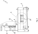
- the machine 1 comprises a fixed frame 2 and at least one tool 4 mounted on a spindle and operative in a machining zone in which the slab L to be machined is positioned.
- the frame 2 comprises a pair of sidewalls 2A, 2B, as shown more clearly in Figures 3a-3d , 4-5 and 6a-6d , and these sidewalls 2A, 2B are positioned at a predetermined distance s1, as shown for example in Figure 6c .
- the tool 4 is movable in the machining zone and its movement is performed by means of suitable movement means.
- these movement means comprise a beam 6 positioned at the top and transversely with respect to a pair of support structures 8 positioned at the ends of the machine 1.
- the beam 6 is supported at its ends by the two support structures 8 and is slidable along a transverse direction on the support structures 8.
- the movement means comprise a spindle-support carriage 10 mounted slidably on the beam 6 along a longitudinal direction and a sleeve 12 mounted on the spindle-support carriage 10 and configured to slide with respect to the spindle-support carriage 10 along a vertical direction.
- the tool 4 is mounted on the tool-holder nose of the spindle which is in turn mounted at the bottom end of the sleeve 12. Therefore, the movement of the sleeve 12 along the vertical direction allows the machining tool 4 to be moved closer to or away from the slab L to be machined.
- the tool 4 may be chosen from the group which comprises drill bits, edge-shaping tools and milling cutters.
- the tool may be replaced with different tools which are kept inside a magazine, not shown in the figures, when they are not used.
- machine 1 comprises:
- the transporting device 14 is a conveyor belt designed to transport the slabs L along a predetermined longitudinal feeding direction X, in particular from a loading zone to the machining zone and from the machining zone to an unloading zone.
- the machine 1 may also comprise a first rollerway and a second rollerway, not shown in the figures, which are positioned in the slab loading zone and unloading zone.
- the supporting and clamping means 16, 17 are designed to clamp the slab L in a machining position.
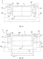
- the slab L is not supported by the conveyor belt 14, as occurs during feeding, but by the supporting and clamping means 16, 17, as shown in Figures 3b and 6b .
- the slab L is at a height from the ground greater than the height at which it is located when it advances on the transporting device 14, as described in detail below.
- the present invention also envisages at least two embodiments of the supporting and clamping means, shown in Figures 3a-3d , 4-5 and in Figures 6a-6d , respectively, and indicated by the reference numbers 16 and 17, respectively.
- the supporting and clamping means 16, 17 comprise two pairs of cylinders 22 which are positioned laterally on opposite sides of the conveyor belt 14, in particular one pair on one side of the conveyor belt 14 and the other pair on the opposite side.
- the cylinders 22 are provided with pistons intended to raise the slabs L in relation to the conveyor belt 14.
- the pistons are housed inside the cylinders 22 and therefore are not visible in the figures.
- these supporting and clamping means 16 comprise two pairs of abutments 20 mounted on the frame 2.
- Figures 3a to 6d show a single pair of cylinders 22 and a single pair of abutments 20.
- one pair of abutments is mounted on a sidewall 2A, and the other pair is mounted on the other sidewall 2B of the frame 2, as is each of the cylinders 22.
- the pairs of cylinders 22 are positioned at a predetermined distance s2, as shown for example in Figure 3b .
- the width w of the conveyor belt 14 is similar to this predetermined distance s2.
- the cylinders 22 are positioned below the feeding plane defined by the upper surface 14A of the conveyor belt 14.
- Each abutment 20 is aligned along a vertical direction with the respective cylinder 22 and arranged in a position raised in relation thereto and to the feeding plane of the slab L.
- the stems 21 support the slab L in the machining position.
- the pistons in order for the pistons to be able to raise the slab L with respect to the conveyor belt 14, the latter must have a width smaller than the width of the slab L. In this way the slab L projects laterally on opposite sides of the conveyor belt 14.
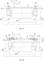
- the machine 1 may also comprise means 26 for adjusting the position of the cylinders 22 and the abutments 20 with respect to the conveyor belt 14 depending on the width of the slab L and means 28 for aligning the slabs with respect to the conveyor belt 14.
- the adjustment means 26 are shown more clearly in Figure 4 and may comprise a slide 30 which is slidable along guides 32 and on which a sidewall 2A of the frame 2 with a pair of cylinders 22 and a pair of abutments 20 is mounted.
- the other sidewall 2B is instead fixed and not adjustable.
- the predetermined distance s2 between the cylinders 22 is greater than the width w of the conveyor belt 14.
- the alignment means 28 are shown more clearly in Figure 5 and may comprise at least one motorized thrusting cylinder 34, preferably two thrusting cylinders, and a respective stop 36 positioned on the opposite side of the conveyor belt 14.
- the thrusting cylinder 34 may be positioned on one of the two sidewalls 2A of the frame 2 and is designed to act on the slab L along a direction substantially parallel to the ground and perpendicular to the feeding direction X so as to bring the slab L up against the stop 36 positioned on the other sidewall 2B of the frame 2.
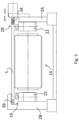
- the second embodiment of the means 17 for supporting and clamping the slabs shown in Figures 6a-6d comprises, for each sidewall 2A, 2A, a pair of substantially horizontal supports 38 parallel to the ground and at least one pair of vertically slidable grippers 40.
- the grippers 40 are mounted on the sliding stems 21 of the respective cylinder pistons 22 and are positioned in a raised position with respect to the supports 38.
- the width w of the conveyor belt 14, in this second embodiment is similar to the distance s1 between the sidewalls 2A, 2B of the frame 2, as shown in Figure 6c , since the cylinders 22 are mounted on the sidewalls 2A, 2B on the outside of the frame 2 compared to the first embodiment.
- the supports 38 act as a support for the slabs L, while the grippers 40 are lowered vertically so as to clamp the slabs L against the supports 38.
- the supports define the machining position for the slab L.
- means 50 are provided for moving the transporting device 14, namely the conveyor belt, which are illustrated more clearly in a particular embodiment shown in Figures 7 and 8 .
- these movement means 50 are configured to move the transporting device 14 from a working position substantially corresponding to the position for machining the slab L into a position spaced at least vertically from the working position, and vice versa.
- the movement means 50 are designed to move the conveyor belt 14 from a raised working position substantially corresponding to the position for machining the slab L into a lowered position spaced from the working position, and vice versa.
- the conveyor belt 14 In the raised position the conveyor belt 14 is positioned at a greater height from the ground than when it is positioned in the lowered position.
- the conveyor belt 14 is moved along at least a vertical direction perpendicular to the ground.
- the movement means 50 may also be configured to move the conveyor belt 14 into a position which is raised with respect to the position for machining the slabs L.
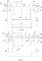
- the conveyor belt 14 is shown in the raised position in Figure 3c and in the lowered position shown in Figure 3d .
- the upper surface 14A of the conveyor belt 14 is in contact with the bottom surface of the slab L so as to support it and prevent it bending during the surface contouring operations carried out on the slab L.
- the conveyor belt 14 In the lowered position the conveyor belt 14 is kept at a predetermined distance d from the slab L after the slab has been clamped, allowing collection of the machining swarf S which falls from the slab L onto the conveyor belt 14 during the formation of through-recesses P, as shown in Figure 3d .
- the machining swarf S is removed by means of activation of the conveyor belt 14 while the slab L is still clamped in the machining position.
- the distance d may also be varied and adjusted depending on the thickness of the slab L to be machined so as to limit the falling height of the machining swarf S and prevent flaking and splintering of the slab L.
- the conveyor belt 14 is moved into the raised position preferably when surface machining operations must be carried out on the slab L so as to support the slab, and into the lowered position preferably when through-recesses P must be formed in the slab L, thus leaving a safety distance d between the slab L and the conveyor belt 14.
- the means 50 for moving the conveyor belt 14 are used before clamping of the slab L by the supporting and clamping means 17.
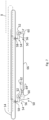
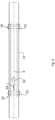
- FIG. 7 and 8 A particular embodiment of the means 50 for moving the conveyor belt 14 is shown in Figures 7 and 8 .
- these movement means 50 are intended to move the conveyor belt 14 principally along the vertical direction and secondarily along a direction parallel to the feeding direction X of the slabs.
- these movement means 50 comprise a pair of pivots 52 which are positioned below the conveyor belt 14 and are rotatable about respective axes Y.
- pivots 52 are positioned at the two longitudinal ends of the belt 14 and the axes of rotation Y are horizontal and perpendicular to the direction of feeding X of the slabs L.
- Each of the pivots 52 comprises a first arm 54 integral with the pivot 52 and the conveyor belt 14.
- the first arm comprises a first portion 56 integral with the pivot 52 and a second portion 58 integral with the conveyor belt 14.
- the two portions 56, 58 are perpendicular to each other, namely an angle of about 90° is defined in the zone where the two portions 56, 58 are joined together.
- the pivots 52 also comprise respective second arms 60; each second arm 60 is fixed to the pivot 52 in a position angularly offset with respect to the first arm 54, preferably at an angle close to 90°, as shown in Figure 7 .
- the first portion 56 of the first arm 54 is substantially horizontal, while the second portion 58 of the first arm 54 and the second arm 60 are substantially vertical and directed downwards.
- the second arm 60 of at least one of the two pivots 52 is connected to a linear actuator 62 with a sliding stem 64.
- the extension or retraction of the stem 64 of the linear actuator 62 causes the rotation of the second arm 60 and therefore the pivot 52 and consequently the raising or lowering of the conveyor belt 14 by means of the first arm 54.
- the second arms 60 of the two pivots 52 may be connected together by means of a rigid connecting bar 66, shown more clearly in Figure 7 .
- the present invention also envisages a method for processing the slabs of natural stone, agglomerate, ceramic or glass material which uses the machine 1 described above.
- the method may comprise a step of positioning the conveyor belt 14 with its upper surface 14A in contact with the bottom surface of the slab L, as shown in Figures 3c and 6c , and/or a step of positioning the conveyor belt 14 with its upper surface 14A located at a predetermined distance d from the bottom surface of the slab L, as shown in Figures 3d and 6d .
- the first step is preferably performed before performing surface-machining of the slab, while the second step is performed preferably before forming a through-recess in the slab.
- the belt In the first case it is possible to prevent the belt from being damaged by the machining tool 4 or the slab from splintering following falling of the machining swarf. In the second case it is possible to prevent bending of the slab caused by the pressure of the machining tool during execution of the surface contouring operations.
Landscapes
- Engineering & Computer Science (AREA)
- Mechanical Engineering (AREA)
- Mining & Mineral Resources (AREA)
- Feeding Of Workpieces (AREA)
- Photographic Processing Devices Using Wet Methods (AREA)
- Processing Of Stones Or Stones Resemblance Materials (AREA)
Claims (17)
- Machine (1) pour l'usinage des dalles (L), comprenant:un dispositif (14) pour transporter les dalles (L) entre deux zones, dont au moins l'une est une zone d'usinage le long d'une direction d'alimentation (X);des moyens (16, 17) pour supporter et serrer les dalles, conçus pour serrer les dalles (L) dans une position d'usinage;au moins un outil (4) pour usiner les dalles, monté sur un mandrin, ledit au moins un outil (4) étant opérationnel dans la zone d'usinage;dans lequel la machine comprend des moyens (50) pour déplacer ledit dispositif de transport (14), configurés pour déplacer ledit dispositif de transport (14) d'une position de travail correspondant sensiblement à ladite position pour usiner les dalles (L) dans une position espacée au moins verticalement de ladite position de travail, et vice versa; etdans laquelle ledit dispositif de transport (14) comprend une courroie transporteuse;caractérisée en ce que lesdits moyens de déplacement (50) sont configurés pour déplacer ladite courroie transporteuse (14) d'une position de travail levée correspondant sensiblement audit positionnement pour l'usinage des dalles (L) dans une position abaissée espacée de ladite position de travail, et vice versa.
- Machine (1) selon la revendication 1, caractérisée en ce que lesdits moyens de déplacement (50) sont configurés pour déplacer ladite courroie transporteuse (14) le long d'au moins une direction verticale perpendiculaire au sol.
- Machine (1) selon la revendication précédente, caractérisée en ce que lesdits moyens de déplacement (50) sont configurés pour déplacer ladite courroie transporteuse (14) dans une autre position levée par rapport à la position pour usiner les dalles (L).
- Machine (1) selon l'une quelconque des revendications précédentes, caractérisée en ce que lesdits moyens de déplacement (50) comprennent une paire de pivots (52) qui sont positionnés au-dessous de ladite courroie transporteuse (14) et peuvent tourner autour des axes (Y) respectifs.
- Machine (1) selon la revendication précédente, caractérisée en ce que chacun desdits pivots (52) comprennent au moins un premier bras (54) solidaire avec le pivot (52) et solidaire avec ladite courroie transporteuse (14).
- Machine (1) selon la revendication précédente, caractérisée en ce que lesdits pivots (52) comprennent des seconds bras (60) respectifs, le second bras (60) d'au moins l'un desdits pivots (52) étant raccordé à un actionneur linéaire (62) afin de provoquer la rotation dudit au moins un pivot (52).
- Machine (1) selon la revendication précédente, caractérisée en ce qu'elle comprend une barre de raccordement (66) conçue pour raccorder les seconds bras (60) desdits pivots (52) afin de permettre la rotation synchrone desdits pivots (52).
- Machine (1) selon la revendication 1, caractérisée en ce que lesdits moyens de support et de serrage (16, 17) comprennent deux paires de cylindres (22) positionnées latéralement sur les côtés opposés de la courroie transporteuse (14).
- Machine selon la revendication précédente, caractérisée en ce que lesdits cylindres (22) sont prévus avec des pistons prévus pour lever les dalles (L) par rapport à la courroie transporteuse (14) et pour supporter les dalles (L) pendant l'usinage.
- Machine (1) selon la revendication précédente, caractérisée en ce que lesdits moyens de support et de serrage (16) comprennent deux paires de butées (20) qui sont alignées avec lesdits cylindres (22) dans une position levée le long d'une direction verticale et sont montées sur un bâti fixe (2) de la machine (1).
- Machine (1) selon la revendication précédente, caractérisée en ce qu'elle comprend des moyens (26) pour régler la position desdits cylindres (22) et desdites butées (20) par rapport à ladite courroie transporteuse (14).
- Machine selon la revendication 10, caractérisée en ce que les paires desdits cylindres (22) sont positionnées à une distance (s2) prédéterminée, la largeur (w) de ladite courroie transporteuse (14) étant similaire à ladite distance (s2) prédéterminée.
- Machine (1) selon la revendication 1, caractérisée en ce qu'elle comprend des moyens (28) pour aligner les dalles (L) par rapport à ladite courroie transporteuse (14).
- Machine (1) selon la revendication 8, caractérisée en ce que lesdits moyens de support et de serrage (17) comprennent au moins deux paires de dispositifs de préhension (40) montées sur les pistons desdits cylindres (22) et pouvant coulisser le long d'une direction verticale et au moins deux paires de supports (38) sensiblement horizontaux qui sont alignés avec lesdits dispositifs de préhension (40) le long de la direction verticale dans la position abaissée.
- Machine selon la revendication précédente, caractérisée en ce qu'elle comprend un bâti (2) avec une paire de parois latérales (2A, 2B) positionnée à une distance (s1) prédéterminée, la largeur (w) de ladite courroie transporteuse (14) étant similaire à ladite distance (s1) prédéterminée.
- Procédé pour usiner des dalles de pierre, de céramique ou de verre, lequel procédé utilise la machine (1) selon l'une quelconque des revendications 1 à 15, caractérisé en ce qu'il comprend une étape consistant à positionner la courroie transporteuse (14) avec sa surface supérieure (14A) en contact avec la surface inférieure des dalles (L) pendant l'usinage de surface des dalles (L).
- Procédé pour usiner des dalles de pierre, de céramique ou de verre, lequel procédé utilise la machine (1) selon l'une quelconque des revendications 1 à 15, caractérisé en ce qu'il comprend une étape consistant à positionner la courroie transporteuse (14) avec sa surface supérieure (14A) à une distance (d) prédéterminée de la surface inférieure de la dalle (L), pendant la formation d'évidements débouchants dans la dalle (L) afin de collecter les copeaux d'usinage (S).
Applications Claiming Priority (2)
| Application Number | Priority Date | Filing Date | Title |
|---|---|---|---|
| IT102020000001954A IT202000001954A1 (it) | 2020-01-31 | 2020-01-31 | Macchina per la lavorazione di lastre |
| PCT/IB2021/050576 WO2021152449A1 (fr) | 2020-01-31 | 2021-01-26 | Machine de traitement de dalles |
Publications (2)
| Publication Number | Publication Date |
|---|---|
| EP4096888A1 EP4096888A1 (fr) | 2022-12-07 |
| EP4096888B1 true EP4096888B1 (fr) | 2024-06-12 |
Family
ID=70480480
Family Applications (1)
| Application Number | Title | Priority Date | Filing Date |
|---|---|---|---|
| EP21706708.1A Active EP4096888B1 (fr) | 2020-01-31 | 2021-01-26 | Machine pour l'usinage des dalles et procédés d'utilisation |
Country Status (5)
| Country | Link |
|---|---|
| US (1) | US20230060723A1 (fr) |
| EP (1) | EP4096888B1 (fr) |
| CA (1) | CA3166205A1 (fr) |
| IT (1) | IT202000001954A1 (fr) |
| WO (1) | WO2021152449A1 (fr) |
Families Citing this family (1)
| Publication number | Priority date | Publication date | Assignee | Title |
|---|---|---|---|---|
| IT202300019674A1 (it) | 2023-09-25 | 2025-03-25 | Breton Spa | Metodo e macchina per la lavorazione di lastre in materiale lapideo o litoide |
Family Cites Families (8)
| Publication number | Priority date | Publication date | Assignee | Title |
|---|---|---|---|---|
| FR2328552A1 (fr) * | 1975-10-09 | 1977-05-20 | Baudot Jean Claude | Machine de preparation automatique de plaques ondulees |
| DE4308032C2 (de) * | 1993-03-13 | 1995-10-05 | Schmidt Rsa Entgrat Tech | Verfahren und Vorrichtung zum Ablängen von Stücken von einem stangenförmigen Profilmaterial |
| TW200526384A (en) * | 2003-09-24 | 2005-08-16 | Mitsuboshi Diamond Ind Co Ltd | Substrate dicing system, substrate manufacturing apparatus, and substrate dicing method |
| ITTO20040275A1 (it) * | 2004-04-30 | 2004-07-30 | Biesse Spa | Centro di lavoro per la lavorazione di lastre di vetro, marmo o simili con sistema automatico di carico delle lastre. |
| IT1391207B1 (it) | 2008-09-30 | 2011-11-18 | Toncelli | Dispositivo auto-bloccante per materiale in lastra e procedimento di bloccaggio ad esso associato. |
| ITVI20110165A1 (it) * | 2011-06-23 | 2012-12-24 | Donatoni Macchine S R L | Sistema per il taglio di lastre in materiale lapideo e metodo d'uso di tale sistema |
| TW201843118A (zh) * | 2017-05-02 | 2018-12-16 | 日商日本電氣硝子股份有限公司 | 板玻璃的製造方法以及製造裝置 |
| IT201700085377A1 (it) * | 2017-07-26 | 2019-01-26 | Biesse Spa | Apparecchiatura a controllo elettronico per tagliare e lavorare lastre di materiale lapideo, naturale o sintetico, o lastre di vetro |
-
2020
- 2020-01-31 IT IT102020000001954A patent/IT202000001954A1/it unknown
-
2021
- 2021-01-26 WO PCT/IB2021/050576 patent/WO2021152449A1/fr not_active Ceased
- 2021-01-26 CA CA3166205A patent/CA3166205A1/fr active Pending
- 2021-01-26 EP EP21706708.1A patent/EP4096888B1/fr active Active
- 2021-01-26 US US17/792,901 patent/US20230060723A1/en active Pending
Also Published As
| Publication number | Publication date |
|---|---|
| CA3166205A1 (fr) | 2021-08-05 |
| EP4096888A1 (fr) | 2022-12-07 |
| IT202000001954A1 (it) | 2021-07-31 |
| US20230060723A1 (en) | 2023-03-02 |
| WO2021152449A1 (fr) | 2021-08-05 |
Similar Documents
| Publication | Publication Date | Title |
|---|---|---|
| KR102333491B1 (ko) | 플레이트 에지 밀링장치 | |
| EP1740359B1 (fr) | Appareil combine pour l'usinage d'articles se presentant en particulier sous la forme de dalles | |
| CN110355830B (zh) | 一种高效率数控六面钻孔机及其加工方式 | |
| EP1591427B1 (fr) | Une station de travaille pour machiner des feuilles de verre, de marbre ou materiau similaire avec un système de chargement automatique des feuilles | |
| EP1810802A1 (fr) | Machine-outil | |
| EP2762273B1 (fr) | Machine-outil | |
| CN104759666B (zh) | 一种提升工件直角精度的铣削方法 | |
| WO2011039700A1 (fr) | Machine permettant de traiter des matériaux sous forme de bloc, notamment des matériaux en pierre naturels et agglomérés, des matériaux en céramique et des matériaux en verre | |
| WO2006057024A1 (fr) | Poste de travail pour la decoupe optimisee de materiaux sous la forme de dalles | |
| US7240415B2 (en) | Machine for processing material in the form of slabs, in particular natural stone material, ceramic material and conglomerate | |
| US11478834B2 (en) | Processing planar workpieces | |
| EP4096888B1 (fr) | Machine pour l'usinage des dalles et procédés d'utilisation | |
| CA3157741A1 (fr) | Cellule de fabrication pourvue d'un porte-outil | |
| CN100396395C (zh) | 用于加工板状工件的机械装置 | |
| EP3426436B1 (fr) | Machine pour usiner des dalles de verre avec un ensemble de commande numérique informatisé et procédé de production associé | |
| EP3628442A1 (fr) | Unité d'agrégat multi-outils pour polir des plaques de matériau en pierre ou de matériau synthétique et machine de polissage fournie avec cette unité | |
| EP4124433B1 (fr) | Machine-outil multiaxiale pour dalles de matériaux relativement fragiles et procédé de gravure | |
| EP4049787B1 (fr) | Machine et procédé pour traiter les bords latéraux de plaques de verre, de plaques en pierre ou de plaques en matière synthétique | |
| EP3827950B1 (fr) | Machine pour l'usinage de panneaux | |
| EP3810366B1 (fr) | Machine pour meuler des dalles | |
| EP1231008A1 (fr) | Machine à travailler des panneaux | |
| KR100932540B1 (ko) | 다면을 가공하는 복합 가공기 | |
| EP4457067B1 (fr) | Procédé de coupe | |
| US20240383172A1 (en) | Machine tool for cutting and engraving slabs | |
| CN113878357A (zh) | 一种门套板加工装置和方法 |
Legal Events
| Date | Code | Title | Description |
|---|---|---|---|
| STAA | Information on the status of an ep patent application or granted ep patent |
Free format text: STATUS: UNKNOWN |
|
| STAA | Information on the status of an ep patent application or granted ep patent |
Free format text: STATUS: THE INTERNATIONAL PUBLICATION HAS BEEN MADE |
|
| PUAI | Public reference made under article 153(3) epc to a published international application that has entered the european phase |
Free format text: ORIGINAL CODE: 0009012 |
|
| STAA | Information on the status of an ep patent application or granted ep patent |
Free format text: STATUS: REQUEST FOR EXAMINATION WAS MADE |
|
| 17P | Request for examination filed |
Effective date: 20220810 |
|
| AK | Designated contracting states |
Kind code of ref document: A1 Designated state(s): AL AT BE BG CH CY CZ DE DK EE ES FI FR GB GR HR HU IE IS IT LI LT LU LV MC MK MT NL NO PL PT RO RS SE SI SK SM TR |
|
| DAV | Request for validation of the european patent (deleted) | ||
| DAX | Request for extension of the european patent (deleted) | ||
| GRAP | Despatch of communication of intention to grant a patent |
Free format text: ORIGINAL CODE: EPIDOSNIGR1 |
|
| STAA | Information on the status of an ep patent application or granted ep patent |
Free format text: STATUS: GRANT OF PATENT IS INTENDED |
|
| INTG | Intention to grant announced |
Effective date: 20240116 |
|
| GRAS | Grant fee paid |
Free format text: ORIGINAL CODE: EPIDOSNIGR3 |
|
| GRAA | (expected) grant |
Free format text: ORIGINAL CODE: 0009210 |
|
| STAA | Information on the status of an ep patent application or granted ep patent |
Free format text: STATUS: THE PATENT HAS BEEN GRANTED |
|
| AK | Designated contracting states |
Kind code of ref document: B1 Designated state(s): AL AT BE BG CH CY CZ DE DK EE ES FI FR GB GR HR HU IE IS IT LI LT LU LV MC MK MT NL NO PL PT RO RS SE SI SK SM TR |
|
| REG | Reference to a national code |
Ref country code: GB Ref legal event code: FG4D |
|
| REG | Reference to a national code |
Ref country code: CH Ref legal event code: EP |
|
| REG | Reference to a national code |
Ref country code: DE Ref legal event code: R096 Ref document number: 602021014341 Country of ref document: DE |
|
| REG | Reference to a national code |
Ref country code: IE Ref legal event code: FG4D |
|
| P01 | Opt-out of the competence of the unified patent court (upc) registered |
Free format text: CASE NUMBER: APP_35200/2024 Effective date: 20240612 |
|
| PG25 | Lapsed in a contracting state [announced via postgrant information from national office to epo] |
Ref country code: BG Free format text: LAPSE BECAUSE OF FAILURE TO SUBMIT A TRANSLATION OF THE DESCRIPTION OR TO PAY THE FEE WITHIN THE PRESCRIBED TIME-LIMIT Effective date: 20240612 |
|
| PG25 | Lapsed in a contracting state [announced via postgrant information from national office to epo] |
Ref country code: FI Free format text: LAPSE BECAUSE OF FAILURE TO SUBMIT A TRANSLATION OF THE DESCRIPTION OR TO PAY THE FEE WITHIN THE PRESCRIBED TIME-LIMIT Effective date: 20240612 Ref country code: HR Free format text: LAPSE BECAUSE OF FAILURE TO SUBMIT A TRANSLATION OF THE DESCRIPTION OR TO PAY THE FEE WITHIN THE PRESCRIBED TIME-LIMIT Effective date: 20240612 |
|
| REG | Reference to a national code |
Ref country code: LT Ref legal event code: MG9D |
|
| PG25 | Lapsed in a contracting state [announced via postgrant information from national office to epo] |
Ref country code: GR Free format text: LAPSE BECAUSE OF FAILURE TO SUBMIT A TRANSLATION OF THE DESCRIPTION OR TO PAY THE FEE WITHIN THE PRESCRIBED TIME-LIMIT Effective date: 20240913 |
|
| REG | Reference to a national code |
Ref country code: NL Ref legal event code: MP Effective date: 20240612 |
|
| PG25 | Lapsed in a contracting state [announced via postgrant information from national office to epo] |
Ref country code: ES Free format text: LAPSE BECAUSE OF FAILURE TO SUBMIT A TRANSLATION OF THE DESCRIPTION OR TO PAY THE FEE WITHIN THE PRESCRIBED TIME-LIMIT Effective date: 20240612 |
|
| PG25 | Lapsed in a contracting state [announced via postgrant information from national office to epo] |
Ref country code: LV Free format text: LAPSE BECAUSE OF FAILURE TO SUBMIT A TRANSLATION OF THE DESCRIPTION OR TO PAY THE FEE WITHIN THE PRESCRIBED TIME-LIMIT Effective date: 20240612 |
|
| PG25 | Lapsed in a contracting state [announced via postgrant information from national office to epo] |
Ref country code: NO Free format text: LAPSE BECAUSE OF FAILURE TO SUBMIT A TRANSLATION OF THE DESCRIPTION OR TO PAY THE FEE WITHIN THE PRESCRIBED TIME-LIMIT Effective date: 20240912 Ref country code: LV Free format text: LAPSE BECAUSE OF FAILURE TO SUBMIT A TRANSLATION OF THE DESCRIPTION OR TO PAY THE FEE WITHIN THE PRESCRIBED TIME-LIMIT Effective date: 20240612 Ref country code: HR Free format text: LAPSE BECAUSE OF FAILURE TO SUBMIT A TRANSLATION OF THE DESCRIPTION OR TO PAY THE FEE WITHIN THE PRESCRIBED TIME-LIMIT Effective date: 20240612 Ref country code: GR Free format text: LAPSE BECAUSE OF FAILURE TO SUBMIT A TRANSLATION OF THE DESCRIPTION OR TO PAY THE FEE WITHIN THE PRESCRIBED TIME-LIMIT Effective date: 20240913 Ref country code: FI Free format text: LAPSE BECAUSE OF FAILURE TO SUBMIT A TRANSLATION OF THE DESCRIPTION OR TO PAY THE FEE WITHIN THE PRESCRIBED TIME-LIMIT Effective date: 20240612 Ref country code: ES Free format text: LAPSE BECAUSE OF FAILURE TO SUBMIT A TRANSLATION OF THE DESCRIPTION OR TO PAY THE FEE WITHIN THE PRESCRIBED TIME-LIMIT Effective date: 20240612 Ref country code: BG Free format text: LAPSE BECAUSE OF FAILURE TO SUBMIT A TRANSLATION OF THE DESCRIPTION OR TO PAY THE FEE WITHIN THE PRESCRIBED TIME-LIMIT Effective date: 20240612 Ref country code: RS Free format text: LAPSE BECAUSE OF FAILURE TO SUBMIT A TRANSLATION OF THE DESCRIPTION OR TO PAY THE FEE WITHIN THE PRESCRIBED TIME-LIMIT Effective date: 20240912 |
|
| PG25 | Lapsed in a contracting state [announced via postgrant information from national office to epo] |
Ref country code: NL Free format text: LAPSE BECAUSE OF FAILURE TO SUBMIT A TRANSLATION OF THE DESCRIPTION OR TO PAY THE FEE WITHIN THE PRESCRIBED TIME-LIMIT Effective date: 20240612 |
|
| REG | Reference to a national code |
Ref country code: AT Ref legal event code: MK05 Ref document number: 1693850 Country of ref document: AT Kind code of ref document: T Effective date: 20240612 |
|
| PG25 | Lapsed in a contracting state [announced via postgrant information from national office to epo] |
Ref country code: NL Free format text: LAPSE BECAUSE OF FAILURE TO SUBMIT A TRANSLATION OF THE DESCRIPTION OR TO PAY THE FEE WITHIN THE PRESCRIBED TIME-LIMIT Effective date: 20240612 |
|
| PG25 | Lapsed in a contracting state [announced via postgrant information from national office to epo] |
Ref country code: PT Free format text: LAPSE BECAUSE OF FAILURE TO SUBMIT A TRANSLATION OF THE DESCRIPTION OR TO PAY THE FEE WITHIN THE PRESCRIBED TIME-LIMIT Effective date: 20241014 |
|
| PG25 | Lapsed in a contracting state [announced via postgrant information from national office to epo] |
Ref country code: PT Free format text: LAPSE BECAUSE OF FAILURE TO SUBMIT A TRANSLATION OF THE DESCRIPTION OR TO PAY THE FEE WITHIN THE PRESCRIBED TIME-LIMIT Effective date: 20241014 |
|
| PG25 | Lapsed in a contracting state [announced via postgrant information from national office to epo] |
Ref country code: PL Free format text: LAPSE BECAUSE OF FAILURE TO SUBMIT A TRANSLATION OF THE DESCRIPTION OR TO PAY THE FEE WITHIN THE PRESCRIBED TIME-LIMIT Effective date: 20240612 |
|
| PG25 | Lapsed in a contracting state [announced via postgrant information from national office to epo] |
Ref country code: EE Free format text: LAPSE BECAUSE OF FAILURE TO SUBMIT A TRANSLATION OF THE DESCRIPTION OR TO PAY THE FEE WITHIN THE PRESCRIBED TIME-LIMIT Effective date: 20240612 |
|
| PG25 | Lapsed in a contracting state [announced via postgrant information from national office to epo] |
Ref country code: IS Free format text: LAPSE BECAUSE OF FAILURE TO SUBMIT A TRANSLATION OF THE DESCRIPTION OR TO PAY THE FEE WITHIN THE PRESCRIBED TIME-LIMIT Effective date: 20241012 Ref country code: AT Free format text: LAPSE BECAUSE OF FAILURE TO SUBMIT A TRANSLATION OF THE DESCRIPTION OR TO PAY THE FEE WITHIN THE PRESCRIBED TIME-LIMIT Effective date: 20240612 |
|
| PG25 | Lapsed in a contracting state [announced via postgrant information from national office to epo] |
Ref country code: CZ Free format text: LAPSE BECAUSE OF FAILURE TO SUBMIT A TRANSLATION OF THE DESCRIPTION OR TO PAY THE FEE WITHIN THE PRESCRIBED TIME-LIMIT Effective date: 20240612 |
|
| PG25 | Lapsed in a contracting state [announced via postgrant information from national office to epo] |
Ref country code: SK Free format text: LAPSE BECAUSE OF FAILURE TO SUBMIT A TRANSLATION OF THE DESCRIPTION OR TO PAY THE FEE WITHIN THE PRESCRIBED TIME-LIMIT Effective date: 20240612 Ref country code: RO Free format text: LAPSE BECAUSE OF FAILURE TO SUBMIT A TRANSLATION OF THE DESCRIPTION OR TO PAY THE FEE WITHIN THE PRESCRIBED TIME-LIMIT Effective date: 20240612 |
|
| PG25 | Lapsed in a contracting state [announced via postgrant information from national office to epo] |
Ref country code: SM Free format text: LAPSE BECAUSE OF FAILURE TO SUBMIT A TRANSLATION OF THE DESCRIPTION OR TO PAY THE FEE WITHIN THE PRESCRIBED TIME-LIMIT Effective date: 20240612 |
|
| PG25 | Lapsed in a contracting state [announced via postgrant information from national office to epo] |
Ref country code: SM Free format text: LAPSE BECAUSE OF FAILURE TO SUBMIT A TRANSLATION OF THE DESCRIPTION OR TO PAY THE FEE WITHIN THE PRESCRIBED TIME-LIMIT Effective date: 20240612 Ref country code: SK Free format text: LAPSE BECAUSE OF FAILURE TO SUBMIT A TRANSLATION OF THE DESCRIPTION OR TO PAY THE FEE WITHIN THE PRESCRIBED TIME-LIMIT Effective date: 20240612 Ref country code: RO Free format text: LAPSE BECAUSE OF FAILURE TO SUBMIT A TRANSLATION OF THE DESCRIPTION OR TO PAY THE FEE WITHIN THE PRESCRIBED TIME-LIMIT Effective date: 20240612 Ref country code: PL Free format text: LAPSE BECAUSE OF FAILURE TO SUBMIT A TRANSLATION OF THE DESCRIPTION OR TO PAY THE FEE WITHIN THE PRESCRIBED TIME-LIMIT Effective date: 20240612 Ref country code: IS Free format text: LAPSE BECAUSE OF FAILURE TO SUBMIT A TRANSLATION OF THE DESCRIPTION OR TO PAY THE FEE WITHIN THE PRESCRIBED TIME-LIMIT Effective date: 20241012 Ref country code: EE Free format text: LAPSE BECAUSE OF FAILURE TO SUBMIT A TRANSLATION OF THE DESCRIPTION OR TO PAY THE FEE WITHIN THE PRESCRIBED TIME-LIMIT Effective date: 20240612 Ref country code: CZ Free format text: LAPSE BECAUSE OF FAILURE TO SUBMIT A TRANSLATION OF THE DESCRIPTION OR TO PAY THE FEE WITHIN THE PRESCRIBED TIME-LIMIT Effective date: 20240612 Ref country code: AT Free format text: LAPSE BECAUSE OF FAILURE TO SUBMIT A TRANSLATION OF THE DESCRIPTION OR TO PAY THE FEE WITHIN THE PRESCRIBED TIME-LIMIT Effective date: 20240612 |
|
| REG | Reference to a national code |
Ref country code: DE Ref legal event code: R097 Ref document number: 602021014341 Country of ref document: DE |
|
| PG25 | Lapsed in a contracting state [announced via postgrant information from national office to epo] |
Ref country code: DK Free format text: LAPSE BECAUSE OF FAILURE TO SUBMIT A TRANSLATION OF THE DESCRIPTION OR TO PAY THE FEE WITHIN THE PRESCRIBED TIME-LIMIT Effective date: 20240612 |
|
| PLBE | No opposition filed within time limit |
Free format text: ORIGINAL CODE: 0009261 |
|
| STAA | Information on the status of an ep patent application or granted ep patent |
Free format text: STATUS: NO OPPOSITION FILED WITHIN TIME LIMIT |
|
| 26N | No opposition filed |
Effective date: 20250313 |
|
| REG | Reference to a national code |
Ref country code: CH Ref legal event code: PL |
|
| PG25 | Lapsed in a contracting state [announced via postgrant information from national office to epo] |
Ref country code: SE Free format text: LAPSE BECAUSE OF FAILURE TO SUBMIT A TRANSLATION OF THE DESCRIPTION OR TO PAY THE FEE WITHIN THE PRESCRIBED TIME-LIMIT Effective date: 20240612 |
|
| PG25 | Lapsed in a contracting state [announced via postgrant information from national office to epo] |
Ref country code: LU Free format text: LAPSE BECAUSE OF NON-PAYMENT OF DUE FEES Effective date: 20250126 Ref country code: MC Free format text: LAPSE BECAUSE OF FAILURE TO SUBMIT A TRANSLATION OF THE DESCRIPTION OR TO PAY THE FEE WITHIN THE PRESCRIBED TIME-LIMIT Effective date: 20240612 |
|
| GBPC | Gb: european patent ceased through non-payment of renewal fee |
Effective date: 20250126 |
|
| PG25 | Lapsed in a contracting state [announced via postgrant information from national office to epo] |
Ref country code: BE Free format text: LAPSE BECAUSE OF NON-PAYMENT OF DUE FEES Effective date: 20250131 Ref country code: GB Free format text: LAPSE BECAUSE OF NON-PAYMENT OF DUE FEES Effective date: 20250126 |
|
| PG25 | Lapsed in a contracting state [announced via postgrant information from national office to epo] |
Ref country code: FR Free format text: LAPSE BECAUSE OF NON-PAYMENT OF DUE FEES Effective date: 20250131 |
|
| PG25 | Lapsed in a contracting state [announced via postgrant information from national office to epo] |
Ref country code: CH Free format text: LAPSE BECAUSE OF NON-PAYMENT OF DUE FEES Effective date: 20250131 |
|
| REG | Reference to a national code |
Ref country code: BE Ref legal event code: MM Effective date: 20250131 |
|
| PG25 | Lapsed in a contracting state [announced via postgrant information from national office to epo] |
Ref country code: IE Free format text: LAPSE BECAUSE OF NON-PAYMENT OF DUE FEES Effective date: 20250126 |
|
| PGFP | Annual fee paid to national office [announced via postgrant information from national office to epo] |
Ref country code: DE Payment date: 20251217 Year of fee payment: 6 |
|
| PGFP | Annual fee paid to national office [announced via postgrant information from national office to epo] |
Ref country code: IT Payment date: 20260107 Year of fee payment: 6 |