EP4096893B1 - Dispositif pour chauffer et sécher au moins un produit en matière non ferromagnétique - Google Patents
Dispositif pour chauffer et sécher au moins un produit en matière non ferromagnétique Download PDFInfo
- Publication number
- EP4096893B1 EP4096893B1 EP21710178.1A EP21710178A EP4096893B1 EP 4096893 B1 EP4096893 B1 EP 4096893B1 EP 21710178 A EP21710178 A EP 21710178A EP 4096893 B1 EP4096893 B1 EP 4096893B1
- Authority
- EP
- European Patent Office
- Prior art keywords
- endless belt
- inductor
- belt
- viewed
- product
- Prior art date
- Legal status (The legal status is an assumption and is not a legal conclusion. Google has not performed a legal analysis and makes no representation as to the accuracy of the status listed.)
- Active
Links
Images


Classifications
-
- B—PERFORMING OPERATIONS; TRANSPORTING
- B29—WORKING OF PLASTICS; WORKING OF SUBSTANCES IN A PLASTIC STATE IN GENERAL
- B29C—SHAPING OR JOINING OF PLASTICS; SHAPING OF MATERIAL IN A PLASTIC STATE, NOT OTHERWISE PROVIDED FOR; AFTER-TREATMENT OF THE SHAPED PRODUCTS, e.g. REPAIRING
- B29C35/00—Heating, cooling or curing, e.g. crosslinking or vulcanising; Apparatus therefor
- B29C35/02—Heating or curing, e.g. crosslinking or vulcanizing during moulding, e.g. in a mould
- B29C35/08—Heating or curing, e.g. crosslinking or vulcanizing during moulding, e.g. in a mould by wave energy or particle radiation
- B29C35/10—Heating or curing, e.g. crosslinking or vulcanizing during moulding, e.g. in a mould by wave energy or particle radiation for articles of indefinite length
-
- B—PERFORMING OPERATIONS; TRANSPORTING
- B05—SPRAYING OR ATOMISING IN GENERAL; APPLYING FLUENT MATERIALS TO SURFACES, IN GENERAL
- B05D—PROCESSES FOR APPLYING FLUENT MATERIALS TO SURFACES, IN GENERAL
- B05D3/00—Pretreatment of surfaces to which liquids or other fluent materials are to be applied; After-treatment of applied coatings, e.g. intermediate treating of an applied coating preparatory to subsequent applications of liquids or other fluent materials
- B05D3/02—Pretreatment of surfaces to which liquids or other fluent materials are to be applied; After-treatment of applied coatings, e.g. intermediate treating of an applied coating preparatory to subsequent applications of liquids or other fluent materials by baking
- B05D3/0254—After-treatment
- B05D3/0281—After-treatment with induction heating
-
- B—PERFORMING OPERATIONS; TRANSPORTING
- B29—WORKING OF PLASTICS; WORKING OF SUBSTANCES IN A PLASTIC STATE IN GENERAL
- B29D—PRODUCING PARTICULAR ARTICLES FROM PLASTICS OR FROM SUBSTANCES IN A PLASTIC STATE
- B29D7/00—Producing flat articles, e.g. films or sheets
- B29D7/01—Films or sheets
-
- F—MECHANICAL ENGINEERING; LIGHTING; HEATING; WEAPONS; BLASTING
- F26—DRYING
- F26B—DRYING SOLID MATERIALS OR OBJECTS BY REMOVING LIQUID THEREFROM
- F26B17/00—Machines or apparatus for drying materials in loose, plastic, or fluidised form, e.g. granules, staple fibres, with progressive movement
- F26B17/02—Machines or apparatus for drying materials in loose, plastic, or fluidised form, e.g. granules, staple fibres, with progressive movement with movement performed by belts carrying the materials; with movement performed by belts propelling the materials over stationary surfaces
- F26B17/04—Machines or apparatus for drying materials in loose, plastic, or fluidised form, e.g. granules, staple fibres, with progressive movement with movement performed by belts carrying the materials; with movement performed by belts propelling the materials over stationary surfaces the belts being all horizontal or slightly inclined
-
- F—MECHANICAL ENGINEERING; LIGHTING; HEATING; WEAPONS; BLASTING
- F26—DRYING
- F26B—DRYING SOLID MATERIALS OR OBJECTS BY REMOVING LIQUID THEREFROM
- F26B3/00—Drying solid materials or objects by processes involving the application of heat
- F26B3/18—Drying solid materials or objects by processes involving the application of heat by conduction, i.e. the heat is conveyed from the heat source, e.g. gas flame, to the materials or objects to be dried by direct contact
- F26B3/20—Drying solid materials or objects by processes involving the application of heat by conduction, i.e. the heat is conveyed from the heat source, e.g. gas flame, to the materials or objects to be dried by direct contact the heat source being a heated surface, e.g. a moving belt or conveyor
-
- F—MECHANICAL ENGINEERING; LIGHTING; HEATING; WEAPONS; BLASTING
- F26—DRYING
- F26B—DRYING SOLID MATERIALS OR OBJECTS BY REMOVING LIQUID THEREFROM
- F26B3/00—Drying solid materials or objects by processes involving the application of heat
- F26B3/32—Drying solid materials or objects by processes involving the application of heat by development of heat within the materials or objects to be dried, e.g. by fermentation or other microbiological action
- F26B3/34—Drying solid materials or objects by processes involving the application of heat by development of heat within the materials or objects to be dried, e.g. by fermentation or other microbiological action by using electrical effects
- F26B3/347—Electromagnetic heating, e.g. induction heating or heating using microwave energy
-
- B—PERFORMING OPERATIONS; TRANSPORTING
- B29—WORKING OF PLASTICS; WORKING OF SUBSTANCES IN A PLASTIC STATE IN GENERAL
- B29C—SHAPING OR JOINING OF PLASTICS; SHAPING OF MATERIAL IN A PLASTIC STATE, NOT OTHERWISE PROVIDED FOR; AFTER-TREATMENT OF THE SHAPED PRODUCTS, e.g. REPAIRING
- B29C35/00—Heating, cooling or curing, e.g. crosslinking or vulcanising; Apparatus therefor
- B29C35/02—Heating or curing, e.g. crosslinking or vulcanizing during moulding, e.g. in a mould
- B29C35/08—Heating or curing, e.g. crosslinking or vulcanizing during moulding, e.g. in a mould by wave energy or particle radiation
- B29C35/0805—Heating or curing, e.g. crosslinking or vulcanizing during moulding, e.g. in a mould by wave energy or particle radiation using electromagnetic radiation
- B29C2035/0811—Heating or curing, e.g. crosslinking or vulcanizing during moulding, e.g. in a mould by wave energy or particle radiation using electromagnetic radiation using induction
Definitions
- the invention relates to a device for heating and drying at least one product made of a non-ferromagnetic material, in particular a film, for example a TAC film or a PVOH film, the device having at least one endless belt made of metal rotating between at least two rollers, wherein the Endless belt has an upper run and a lower run, and an outside of the upper run forms a transport surface for the product, the device having a heating device for heating the product.
- a non-ferromagnetic material in particular a film, for example a TAC film or a PVOH film
- the device having at least one endless belt made of metal rotating between at least two rollers, wherein the Endless belt has an upper run and a lower run, and an outside of the upper run forms a transport surface for the product, the device having a heating device for heating the product.
- films in particular triacetate films, which are used in particular for the production of LCD screens, or PVOH films, which are used, for example, for packaging.
- films of any other type can also be produced, for example films based on renewable raw materials, in particular nano-cellulose films.
- film also includes films.
- the endless belt is deflected by approximately 180° by the deflection roller.
- the upper run and lower run essentially run parallel to each other.
- the upper strand often forms a support surface and/or transport surface for a medium, which is applied, for example in liquid form, to the moving endless belt which runs between the drive roller and the deflection roller and which can be made of metal.
- the endless belt is heated by means of heating elements, which, due to the design, usually extend at least over the entire width of the endless belt, in order to dry the product.
- heating elements due to the design, usually extend at least over the entire width of the endless belt, in order to dry the product.
- the endless belt forms between the belt edges that are not covered by the product and the middle area of the endless belt conventionally produces a temperature difference.
- a higher temperature usually occurs in the uncovered edge regions of the band than in the band sections covered by the product, since the covered band sections are cooled by evaporation of solvent from the product.
- the at least one heating device is designed as an induction heater and has at least one inductor, the maximum extent of which, viewed transversely to a circumferential direction of the endless belt, is smaller than a bandwidth of the endless belt, whereby the at least one inductor, viewed in a band transverse direction of the endless band, extends at least over a band center and areas of the endless band adjoining the band center on both sides.
- the solution according to the invention enables very homogeneous and targeted heating of the product without directly heating the strip edges themselves, which results in significantly more uniform drying of the product.
- the at least one inductor is a cross-field inductor.
- the use of a cross-field inductor has proven to be particularly advantageous for drying flat products that have a large width-to-thickness ratio.
- a cross-field inductor when using a cross-field inductor a very uniform temperature profile across the product width. It has also been found that if there is a transverse weld in the strip, a very uniform temperature distribution between the transverse weld and the areas surrounding it can be achieved by using the transverse field inductor.
- the at least one inductor viewed in the transverse direction of the endless belt, extends over at least two thirds of the bandwidth of the endless belt.
- the endless belt viewed in the transverse direction of the endless belt, has a product zone which is covered by the product in an operating state of the device, whereby the product zone, viewed in the transverse direction of the belt, has a smaller width than the endless belt and the inductor, viewed in the transverse direction of the endless belt, extends essentially over the width of the product zone.
- a variant has proven to be particularly advantageous with regard to the heating of the endless belt, in which the at least one inductor is arranged between the upper run and the lower run, with at least one spacer, in particular in the form of a sliding plate, preferably being arranged between the inductor and the upper run.
- the arrangement of the optional spacer ensures a constant coupling distance between the endless belt and the inductor and thus optimal energy transfer.
- one of the at least two rollers is a casting roller, over which one Casting device for applying the product is arranged, wherein the at least one inductor, viewed in the material flow direction, is arranged at the height of the casting roller and in front of the casting device or, viewed in the material flow direction, after the casting roller and covering at least a section of at least a first quarter of the upper run.
- Particularly good control of the drying process can be achieved by arranging at least two inductors one behind the other, viewed in a direction of rotation of the endless belt.
- the drying process can be further optimized in that the device has at least one nozzle box, each with at least one outflow opening for a gaseous medium pointing towards an underside of the upper run.
- the at least one nozzle box is arranged after the at least one inductor, viewed in a material flow direction.
- the drying process can be further designed and improved more uniformly in that the at least one outflow opening of the at least one nozzle box, viewed in the transverse direction of the endless belt, is at least over two thirds of the belt width, in particular essentially over the entire product width or essentially over the entire belt width of the endless belt, extends.
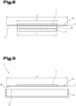
- a device 1 for heating and drying a product 2 made of a non-ferromagnetic material, in particular a film, for example a TAC film or a PVOH film has an endless belt 5 made of metal rotating between two rollers 3, 4.
- the endless belt 5 has an upper run 6 and a lower run 7.
- the device 1 has one or more heating devices 8 designed as induction heaters for heating the product 2.
- the heating device 8 has an inductor 9 for heating the endless belt 5 or the product 2.
- the inductor 9 can be connected to a frequency converter 8a and is preferably designed as a transverse field inductor, so that the field lines of the alternating magnetic field run perpendicular to the surface of the endless belt 5.
- the inductor 9 can be arranged between the upper run 6 and the lower run 7. Alternatively or additionally, the inductor 9 or another inductor 9 can be arranged above or below the roller 3.
- the roller 3 serves as a casting roller over which a casting device 11 for applying the product 2 to the upper run 6 of the endless belt 5 can be arranged.
- the inductor 9 can, for example, be arranged in front of the casting device 11 when viewed in the material flow direction. Viewed in the material flow direction, the inductor 9 can also be arranged after the roller 3 serving as a casting roller. Viewed in a direction of rotation of the endless belt 5, two or more inductors 9 can also be arranged one behind the other.
- inductor 9 arranged in front of the casting device 11
- one or more inductors 9 can be arranged after the casting device 11.
- the inductor 9 can also be arranged above the upper run 6. It goes without saying that several inductors 9 can also be arranged above the upper run 6.
- An inductor 9 arranged after the roller 3 preferably covers a section of at least a first quarter of the upper run 6 and is therefore located very close to the point at which the product 2 is applied to the endless belt 5.
- the extension 1 of the inductor 9 transverse to a circumferential direction of the endless belt 5 is smaller than a bandwidth b of the endless belt 5. Furthermore, the inductor 9, viewed in a transverse direction of the endless belt 5, extends at least over a belt center and areas of the endless belt adjoining the belt center on both sides 5. The inductor 9 preferably extends over at least two thirds of the bandwidth b of the endless belt 5 when viewed in the transverse direction of the endless belt 5.
- the endless belt 5, viewed in the transverse direction of the endless belt 5, has a product zone p, which is covered by the product 2 in an operating state of the device 1. Viewed in the transverse direction of the belt, the product zone p has a smaller width than the endless belt 5.
- the inductor 9 preferably extends essentially over the width of the product zone p when viewed in the transverse direction of the endless belt 5.
- a spacer 10, in particular in the form of a sliding plate, is preferably arranged between the inductor 9 and the upper run 6 in order to keep a constant distance between the inductor 9 and the upper run 6. This applies in particular to an embodiment in which the inductor 9 is arranged between the upper run 6 and the lower run 7.
- one or more nozzle boxes 12 can be provided, through which a hot gas or gas mixture, in particular hot air, is directed against an in Fig. 3 with the reference number 6b marked underside of the upper run 6 flows.
- the at least one nozzle box 12 is arranged after the at least one inductor 9 when viewed in a material flow direction.
- a nozzle box 12 has an outflow opening 13 for a gaseous medium.
- the outflow opening 13 of the nozzle box 12 extends, viewed in the transverse direction of the endless belt 5, at least over two thirds of the bandwidth b, in particular essentially over the entire bandwidth of the endless belt 5 or as in Fig. 4 shown, essentially across the entire product range p.
Landscapes
- Engineering & Computer Science (AREA)
- Mechanical Engineering (AREA)
- General Engineering & Computer Science (AREA)
- Microbiology (AREA)
- Life Sciences & Earth Sciences (AREA)
- Health & Medical Sciences (AREA)
- Physics & Mathematics (AREA)
- Thermal Sciences (AREA)
- Electromagnetism (AREA)
- Oral & Maxillofacial Surgery (AREA)
- Biomedical Technology (AREA)
- Biotechnology (AREA)
- Toxicology (AREA)
- Molecular Biology (AREA)
- Drying Of Solid Materials (AREA)
- Moulding By Coating Moulds (AREA)
Claims (8)
- Dispositif (1) pour le chauffage et le séchage d'au moins un produit (2) en matériau non ferromagnétique, plus particulièrement d'un film, par exemple d'un film TAC ou d'un film PVOH, dans lequel le dispositif (1) comprend au moins une bande sans fin (5) en métal circulant entre deux rouleaux (3, 4), dans lequel la bande sans fin (5) comprend un brin supérieur (6) et un brin inférieur (7), et une face externe de bande (6a) du brin supérieur (6) constitue une surface de transport pour le produit (2), dans lequel le dispositif (1) comprend au moins un dispositif de chauffage (8) pour le chauffage du produit (2), dans lequel un des au moins deux rouleaux (3, 4) est un rouleau de coulée par au-dessus duquel un dispositif de coulée (11) est disposé pour l'application du produit (2), caractérisé en ce que l'au moins un dispositif de chauffage (8) est conçu comme un chauffage à induction et comprend au moins un inducteur (9) dont l'extension maximale (1), vue transversalement par rapport à une direction circonférentielle de la bande sans fin (5), est inférieure à une largeur de bande (b) de la bande sans fin, dans lequel l'au moins un inducteur (9) s'étend, vue dans une direction transversale de la bande sans fin, au moins au-dessus d'un centre de bande et des deux côtés sur les zones adjacentes au centre de bande de la bande sans fin (5), dans lequel l'au moins un inducteur (9) est disposé, vu dans la direction d'écoulement du matériau, à la hauteur du rouleau de coulée et avant le rouleau de coulée (11) ou, vu dans la direction d'écoulement du matériau, après le rouleau de coulée et de façon à recouvrir au moins une portion d'au moins un premier quart du brin supérieur (6).
- Dispositif selon la revendication 1, caractérisé en ce que l'au moins un inducteur (9) est un inducteur à champ transversal.
- Dispositif selon la revendication 1 ou 2, caractérisé en ce que l'au moins un inducteur (9) s'étend, vu dans la direction transversale de la bande sans fin (5), sur au moins deux tiers de la largeur de bande (b) de la bande sans fin (5).
- Dispositif selon l'une des revendications 1 à 3, caractérisé en ce que l'au moins un inducteur (9) est disposé entre le brin supérieur (6) et le brin inférieur (7), dans lequel, de préférence, entre l'inducteur (9) et le brin supérieur (6), est disposé au moins une entretoise (10), plus particulièrement sous la forme d'une plaque coulissante.
- Dispositif selon l'une des revendications 1 à 4, caractérisé en ce qu'au moins deux inducteurs (9) sont disposés l'un derrière l'autre, vus dans une direction circonférentielle de la bande sans fin (5).
- Dispositif selon l'une des revendications 1 à 5, caractérisé en ce qu'il comprend au moins un caisson à buses (12) avec respectivement une ouverture de sortie (13), orientée contre une face inférieure (6b) du brin supérieur (6) pour un milieu gazeux.
- Dispositif selon la revendication 6, caractérisé en ce que l'au moins un caisson à buses (12) est disposé, vu dans une direction d'écoulement du matériau, après l'au moins un inducteur (9).
- Dispositif selon la revendication 6 ou 7, caractérisé en ce que l'au moins une ouverture de sortie (13) de l'au moins un caisson à buses (12) s'étend, vue dans la direction transversale de la bande sans fin (5), sur au moins deux tiers de la largeur de bande (b), plus particulièrement globalement sur toute la largeur du produit ou globalement sur toute la largeur de bande de la bande sans fin (5).
Applications Claiming Priority (2)
| Application Number | Priority Date | Filing Date | Title |
|---|---|---|---|
| AT500632020 | 2020-01-27 | ||
| PCT/AT2021/060027 WO2021151133A1 (fr) | 2020-01-27 | 2021-01-26 | Dispositif de chauffage et de séchage d'au moins un produit fabriqué à partir d'un matériau non ferromagnetique |
Publications (3)
| Publication Number | Publication Date |
|---|---|
| EP4096893A1 EP4096893A1 (fr) | 2022-12-07 |
| EP4096893C0 EP4096893C0 (fr) | 2023-12-13 |
| EP4096893B1 true EP4096893B1 (fr) | 2023-12-13 |
Family
ID=74859157
Family Applications (1)
| Application Number | Title | Priority Date | Filing Date |
|---|---|---|---|
| EP21710178.1A Active EP4096893B1 (fr) | 2020-01-27 | 2021-01-26 | Dispositif pour chauffer et sécher au moins un produit en matière non ferromagnétique |
Country Status (3)
| Country | Link |
|---|---|
| EP (1) | EP4096893B1 (fr) |
| CN (1) | CN115210054B (fr) |
| WO (1) | WO2021151133A1 (fr) |
Family Cites Families (17)
| Publication number | Priority date | Publication date | Assignee | Title |
|---|---|---|---|---|
| DE1454995A1 (de) * | 1965-07-12 | 1969-09-18 | Bahlsen Werner | Verfahren und Vorrichtung zum Verbinden von Oberflaechen thermoplastischer Kunststoffe |
| JPS6298588A (ja) * | 1985-10-25 | 1987-05-08 | 日本軽金属株式会社 | 横磁束型電磁誘導加熱装置 |
| EP0509374B1 (fr) * | 1991-04-18 | 1998-03-04 | Alltrista Corporation | Procédé et appareil pour sécher et cuire un revêtement d'un substrat métallique |
| JP2002110336A (ja) * | 2000-09-27 | 2002-04-12 | Fuji Xerox Co Ltd | 電磁誘導加熱装置及びこれを用いた画像記録装置 |
| JP4867122B2 (ja) * | 2001-09-28 | 2012-02-01 | コニカミノルタホールディングス株式会社 | セルロースエステルフィルムの製造方法 |
| US20060071363A1 (en) * | 2003-01-07 | 2006-04-06 | Mitsubishi Rayon Co., Ltd | Belt type continuous plate manufacturing device and method of manufacturing sheet polymer |
| AT500219B1 (de) * | 2003-05-22 | 2007-11-15 | Masterfoods Austria Ohg | Verfahren und vorrichtung zur wärmebehandlung von nahrungsmitteln bzw. futtermitteln, insbesondere zur herstellung von backwaren, wie waffelprodukten |
| US7323666B2 (en) * | 2003-12-08 | 2008-01-29 | Saint-Gobain Performance Plastics Corporation | Inductively heatable components |
| JP4607779B2 (ja) * | 2005-03-25 | 2011-01-05 | 富士フイルム株式会社 | ポリマーフイルムの製造方法 |
| JP4794954B2 (ja) * | 2005-09-13 | 2011-10-19 | キヤノン株式会社 | 画像加熱装置 |
| JP4933161B2 (ja) * | 2006-06-08 | 2012-05-16 | キヤノン株式会社 | 画像加熱装置 |
| CN101560598B (zh) * | 2008-04-17 | 2011-05-11 | 天津天高感应加热有限公司 | 适用于薄金属窄带热处理的感应加热装置 |
| US20150202830A1 (en) * | 2014-01-17 | 2015-07-23 | Nike, Inc. | Adjustable Conveyance Curing Method |
| JP2015182235A (ja) * | 2014-03-20 | 2015-10-22 | 日本ゼオン株式会社 | 賦型フィルムの製造方法及び製造装置 |
| WO2016035867A1 (fr) * | 2014-09-03 | 2016-03-10 | 新日鐵住金株式会社 | Dispositif de chauffage inductif pour bande métallique |
| EP3025799B2 (fr) * | 2014-11-28 | 2020-04-15 | SMS group GmbH | Installation de laminage |
| DE202015102417U1 (de) * | 2015-05-11 | 2016-06-14 | Dieffenbacher GmbH Maschinen- und Anlagenbau | Vorrichtung zur kontinuierlichen Herstellung von Werkstoffen |
-
2021
- 2021-01-26 EP EP21710178.1A patent/EP4096893B1/fr active Active
- 2021-01-26 WO PCT/AT2021/060027 patent/WO2021151133A1/fr not_active Ceased
- 2021-01-26 CN CN202180010418.9A patent/CN115210054B/zh active Active
Also Published As
| Publication number | Publication date |
|---|---|
| EP4096893C0 (fr) | 2023-12-13 |
| WO2021151133A1 (fr) | 2021-08-05 |
| EP4096893A1 (fr) | 2022-12-07 |
| CN115210054B (zh) | 2024-01-30 |
| CN115210054A (zh) | 2022-10-18 |
Similar Documents
| Publication | Publication Date | Title |
|---|---|---|
| AT500219A1 (de) | Vorrichtung zur wärmebehandlung von nahrungsmitteln bzw. von futtermitteln, insbesondere zum backen von teigen, und anlage zur herstellung von aus gebackenem gut hergestellten produkten | |
| EP3234204B1 (fr) | Dispositif et procédé de traitement en continu d'une bande métallique | |
| EP3069092B1 (fr) | Appareil et procédé pour sécher une bande de matériel | |
| EP2722112B1 (fr) | Dispositif et procédé destinés au traitement continu d'une bande métallique | |
| WO1998023426A1 (fr) | Dispositif pour la fabrication de pieces moulees | |
| WO2017017150A1 (fr) | Procédé et dispositif de variation de température, adaptative en termes de planéité, de bandes métalliques | |
| EP3235388B2 (fr) | Dispositif d'application d'une bande de colle sur une bande d'enrobage en forme de tige de l'industrie de traitement du tabac | |
| DE2742320A1 (de) | Vorrichtung zum kuehlen von erwaermtem gut | |
| WO2018103841A1 (fr) | Dispositif de thermorégulation pour thermoréguler un élément structural | |
| EP4096893A1 (fr) | Dispositif de chauffage et de séchage d'au moins un produit fabriqué à partir d'un matériau non ferromagnetique | |
| DE102014100651B4 (de) | Luftdichtungsvorrichtung für einen Sprühapparat in einer Papierherstellungsmaschine | |
| DE19934557C2 (de) | Vorrichtung zum Kühlen von auf einer Förderstrecke geförderten Metallbändern oder -blechen | |
| DE1950484A1 (de) | Vorrichtung zum Beschichten von Bahnmaterial | |
| DE10114381A1 (de) | Verfahren zur kontinuierlichen Herstellung von Holzspanplatten und ähnlichen bahnförmigen Plattenwerkstoffen und dafür geeignete Doppelbandpresse | |
| EP3382082A1 (fr) | Dispositif de fabrication d'un tissu non-tissé à partir de filaments continus | |
| EP3007874B1 (fr) | Tambour de renvoi pouvant être chauffé ou refroidi, destiné à une installation de coulée en bande | |
| EP3169500B1 (fr) | Un dispositif avec au moins une bande sans fin | |
| EP1425088B1 (fr) | Dispositif de production de granules | |
| EP3118128B1 (fr) | Dispositif de retractation | |
| DE102017130159B4 (de) | Entsorgung unverpressten Materials in einer Presse zum kontinuierlichen Herstellen von Werkstoffplatten | |
| CH646342A5 (en) | Apparatus for feeding materials to a conveyor belt arranged below it | |
| DE102013212952A1 (de) | Vorrichtung und Verfahren zum Stützen eines Stranges beim Stranggießen | |
| DE4000355A1 (de) | Vorrichtung zum erwaermen von extrudiertem strangmaterial | |
| EP3250742B1 (fr) | Caisson d'air d'une machine d'équipement | |
| DE1957578A1 (de) | Vorrichtung zur Folien-Laengsreckung |
Legal Events
| Date | Code | Title | Description |
|---|---|---|---|
| STAA | Information on the status of an ep patent application or granted ep patent |
Free format text: STATUS: UNKNOWN |
|
| STAA | Information on the status of an ep patent application or granted ep patent |
Free format text: STATUS: THE INTERNATIONAL PUBLICATION HAS BEEN MADE |
|
| PUAI | Public reference made under article 153(3) epc to a published international application that has entered the european phase |
Free format text: ORIGINAL CODE: 0009012 |
|
| STAA | Information on the status of an ep patent application or granted ep patent |
Free format text: STATUS: REQUEST FOR EXAMINATION WAS MADE |
|
| 17P | Request for examination filed |
Effective date: 20220826 |
|
| AK | Designated contracting states |
Kind code of ref document: A1 Designated state(s): AL AT BE BG CH CY CZ DE DK EE ES FI FR GB GR HR HU IE IS IT LI LT LU LV MC MK MT NL NO PL PT RO RS SE SI SK SM TR |
|
| DAV | Request for validation of the european patent (deleted) | ||
| DAX | Request for extension of the european patent (deleted) | ||
| GRAP | Despatch of communication of intention to grant a patent |
Free format text: ORIGINAL CODE: EPIDOSNIGR1 |
|
| STAA | Information on the status of an ep patent application or granted ep patent |
Free format text: STATUS: GRANT OF PATENT IS INTENDED |
|
| RIC1 | Information provided on ipc code assigned before grant |
Ipc: B29C 35/08 20060101ALN20230606BHEP Ipc: F26B 3/20 20060101ALI20230606BHEP Ipc: F26B 17/04 20060101ALI20230606BHEP Ipc: C08J 5/18 20060101ALI20230606BHEP Ipc: B29D 7/01 20060101ALI20230606BHEP Ipc: F26B 3/347 20060101ALI20230606BHEP Ipc: B05D 3/02 20060101ALI20230606BHEP Ipc: B29C 35/10 20060101AFI20230606BHEP |
|
| RIC1 | Information provided on ipc code assigned before grant |
Ipc: B29C 35/08 20060101ALN20230616BHEP Ipc: F26B 3/20 20060101ALI20230616BHEP Ipc: F26B 17/04 20060101ALI20230616BHEP Ipc: C08J 5/18 20060101ALI20230616BHEP Ipc: B29D 7/01 20060101ALI20230616BHEP Ipc: F26B 3/347 20060101ALI20230616BHEP Ipc: B05D 3/02 20060101ALI20230616BHEP Ipc: B29C 35/10 20060101AFI20230616BHEP |
|
| INTG | Intention to grant announced |
Effective date: 20230707 |
|
| GRAS | Grant fee paid |
Free format text: ORIGINAL CODE: EPIDOSNIGR3 |
|
| GRAA | (expected) grant |
Free format text: ORIGINAL CODE: 0009210 |
|
| STAA | Information on the status of an ep patent application or granted ep patent |
Free format text: STATUS: THE PATENT HAS BEEN GRANTED |
|
| AK | Designated contracting states |
Kind code of ref document: B1 Designated state(s): AL AT BE BG CH CY CZ DE DK EE ES FI FR GB GR HR HU IE IS IT LI LT LU LV MC MK MT NL NO PL PT RO RS SE SI SK SM TR |
|
| REG | Reference to a national code |
Ref country code: GB Ref legal event code: FG4D Free format text: NOT ENGLISH |
|
| REG | Reference to a national code |
Ref country code: CH Ref legal event code: EP |
|
| REG | Reference to a national code |
Ref country code: DE Ref legal event code: R096 Ref document number: 502021002180 Country of ref document: DE |
|
| REG | Reference to a national code |
Ref country code: IE Ref legal event code: FG4D Free format text: LANGUAGE OF EP DOCUMENT: GERMAN |
|
| U01 | Request for unitary effect filed |
Effective date: 20240112 |
|
| U07 | Unitary effect registered |
Designated state(s): AT BE BG DE DK EE FI FR IT LT LU LV MT NL PT SE SI Effective date: 20240125 |
|
| U20 | Renewal fee for the european patent with unitary effect paid |
Year of fee payment: 4 Effective date: 20240130 |
|
| PG25 | Lapsed in a contracting state [announced via postgrant information from national office to epo] |
Ref country code: GR Free format text: LAPSE BECAUSE OF FAILURE TO SUBMIT A TRANSLATION OF THE DESCRIPTION OR TO PAY THE FEE WITHIN THE PRESCRIBED TIME-LIMIT Effective date: 20240314 |
|
| PG25 | Lapsed in a contracting state [announced via postgrant information from national office to epo] |
Ref country code: ES Free format text: LAPSE BECAUSE OF FAILURE TO SUBMIT A TRANSLATION OF THE DESCRIPTION OR TO PAY THE FEE WITHIN THE PRESCRIBED TIME-LIMIT Effective date: 20231213 |
|
| PG25 | Lapsed in a contracting state [announced via postgrant information from national office to epo] |
Ref country code: GR Free format text: LAPSE BECAUSE OF FAILURE TO SUBMIT A TRANSLATION OF THE DESCRIPTION OR TO PAY THE FEE WITHIN THE PRESCRIBED TIME-LIMIT Effective date: 20240314 Ref country code: ES Free format text: LAPSE BECAUSE OF FAILURE TO SUBMIT A TRANSLATION OF THE DESCRIPTION OR TO PAY THE FEE WITHIN THE PRESCRIBED TIME-LIMIT Effective date: 20231213 |
|
| PG25 | Lapsed in a contracting state [announced via postgrant information from national office to epo] |
Ref country code: RS Free format text: LAPSE BECAUSE OF FAILURE TO SUBMIT A TRANSLATION OF THE DESCRIPTION OR TO PAY THE FEE WITHIN THE PRESCRIBED TIME-LIMIT Effective date: 20231213 Ref country code: NO Free format text: LAPSE BECAUSE OF FAILURE TO SUBMIT A TRANSLATION OF THE DESCRIPTION OR TO PAY THE FEE WITHIN THE PRESCRIBED TIME-LIMIT Effective date: 20240313 Ref country code: HR Free format text: LAPSE BECAUSE OF FAILURE TO SUBMIT A TRANSLATION OF THE DESCRIPTION OR TO PAY THE FEE WITHIN THE PRESCRIBED TIME-LIMIT Effective date: 20231213 |
|
| PG25 | Lapsed in a contracting state [announced via postgrant information from national office to epo] |
Ref country code: IS Free format text: LAPSE BECAUSE OF FAILURE TO SUBMIT A TRANSLATION OF THE DESCRIPTION OR TO PAY THE FEE WITHIN THE PRESCRIBED TIME-LIMIT Effective date: 20240413 |
|
| PG25 | Lapsed in a contracting state [announced via postgrant information from national office to epo] |
Ref country code: CZ Free format text: LAPSE BECAUSE OF FAILURE TO SUBMIT A TRANSLATION OF THE DESCRIPTION OR TO PAY THE FEE WITHIN THE PRESCRIBED TIME-LIMIT Effective date: 20231213 |
|
| PG25 | Lapsed in a contracting state [announced via postgrant information from national office to epo] |
Ref country code: SK Free format text: LAPSE BECAUSE OF FAILURE TO SUBMIT A TRANSLATION OF THE DESCRIPTION OR TO PAY THE FEE WITHIN THE PRESCRIBED TIME-LIMIT Effective date: 20231213 |
|
| PG25 | Lapsed in a contracting state [announced via postgrant information from national office to epo] |
Ref country code: SM Free format text: LAPSE BECAUSE OF FAILURE TO SUBMIT A TRANSLATION OF THE DESCRIPTION OR TO PAY THE FEE WITHIN THE PRESCRIBED TIME-LIMIT Effective date: 20231213 Ref country code: SK Free format text: LAPSE BECAUSE OF FAILURE TO SUBMIT A TRANSLATION OF THE DESCRIPTION OR TO PAY THE FEE WITHIN THE PRESCRIBED TIME-LIMIT Effective date: 20231213 Ref country code: RO Free format text: LAPSE BECAUSE OF FAILURE TO SUBMIT A TRANSLATION OF THE DESCRIPTION OR TO PAY THE FEE WITHIN THE PRESCRIBED TIME-LIMIT Effective date: 20231213 Ref country code: IS Free format text: LAPSE BECAUSE OF FAILURE TO SUBMIT A TRANSLATION OF THE DESCRIPTION OR TO PAY THE FEE WITHIN THE PRESCRIBED TIME-LIMIT Effective date: 20240413 Ref country code: CZ Free format text: LAPSE BECAUSE OF FAILURE TO SUBMIT A TRANSLATION OF THE DESCRIPTION OR TO PAY THE FEE WITHIN THE PRESCRIBED TIME-LIMIT Effective date: 20231213 |
|
| PG25 | Lapsed in a contracting state [announced via postgrant information from national office to epo] |
Ref country code: PL Free format text: LAPSE BECAUSE OF FAILURE TO SUBMIT A TRANSLATION OF THE DESCRIPTION OR TO PAY THE FEE WITHIN THE PRESCRIBED TIME-LIMIT Effective date: 20231213 |
|
| PG25 | Lapsed in a contracting state [announced via postgrant information from national office to epo] |
Ref country code: PL Free format text: LAPSE BECAUSE OF FAILURE TO SUBMIT A TRANSLATION OF THE DESCRIPTION OR TO PAY THE FEE WITHIN THE PRESCRIBED TIME-LIMIT Effective date: 20231213 |
|
| REG | Reference to a national code |
Ref country code: CH Ref legal event code: PL |
|
| REG | Reference to a national code |
Ref country code: DE Ref legal event code: R097 Ref document number: 502021002180 Country of ref document: DE |
|
| PG25 | Lapsed in a contracting state [announced via postgrant information from national office to epo] |
Ref country code: MC Free format text: LAPSE BECAUSE OF FAILURE TO SUBMIT A TRANSLATION OF THE DESCRIPTION OR TO PAY THE FEE WITHIN THE PRESCRIBED TIME-LIMIT Effective date: 20231213 |
|
| PLBE | No opposition filed within time limit |
Free format text: ORIGINAL CODE: 0009261 |
|
| STAA | Information on the status of an ep patent application or granted ep patent |
Free format text: STATUS: NO OPPOSITION FILED WITHIN TIME LIMIT |
|
| PG25 | Lapsed in a contracting state [announced via postgrant information from national office to epo] |
Ref country code: CH Free format text: LAPSE BECAUSE OF NON-PAYMENT OF DUE FEES Effective date: 20240131 |
|
| PG25 | Lapsed in a contracting state [announced via postgrant information from national office to epo] |
Ref country code: CH Free format text: LAPSE BECAUSE OF NON-PAYMENT OF DUE FEES Effective date: 20240131 |
|
| 26N | No opposition filed |
Effective date: 20240916 |
|
| PG25 | Lapsed in a contracting state [announced via postgrant information from national office to epo] |
Ref country code: IE Free format text: LAPSE BECAUSE OF NON-PAYMENT OF DUE FEES Effective date: 20240126 |
|
| PG25 | Lapsed in a contracting state [announced via postgrant information from national office to epo] |
Ref country code: IE Free format text: LAPSE BECAUSE OF NON-PAYMENT OF DUE FEES Effective date: 20240126 |
|
| U20 | Renewal fee for the european patent with unitary effect paid |
Year of fee payment: 5 Effective date: 20250127 |
|
| PG25 | Lapsed in a contracting state [announced via postgrant information from national office to epo] |
Ref country code: CY Free format text: LAPSE BECAUSE OF FAILURE TO SUBMIT A TRANSLATION OF THE DESCRIPTION OR TO PAY THE FEE WITHIN THE PRESCRIBED TIME-LIMIT; INVALID AB INITIO Effective date: 20210126 |
|
| PG25 | Lapsed in a contracting state [announced via postgrant information from national office to epo] |
Ref country code: HU Free format text: LAPSE BECAUSE OF FAILURE TO SUBMIT A TRANSLATION OF THE DESCRIPTION OR TO PAY THE FEE WITHIN THE PRESCRIBED TIME-LIMIT; INVALID AB INITIO Effective date: 20210126 |
|
| PG25 | Lapsed in a contracting state [announced via postgrant information from national office to epo] |
Ref country code: TR Free format text: LAPSE BECAUSE OF FAILURE TO SUBMIT A TRANSLATION OF THE DESCRIPTION OR TO PAY THE FEE WITHIN THE PRESCRIBED TIME-LIMIT Effective date: 20231213 |
|
| U20 | Renewal fee for the european patent with unitary effect paid |
Year of fee payment: 6 Effective date: 20260119 |
|
| PGFP | Annual fee paid to national office [announced via postgrant information from national office to epo] |
Ref country code: GB Payment date: 20260123 Year of fee payment: 6 |