EP4096925B1 - Mehrschichtige folie - Google Patents
Mehrschichtige folie Download PDFInfo
- Publication number
- EP4096925B1 EP4096925B1 EP21747741.3A EP21747741A EP4096925B1 EP 4096925 B1 EP4096925 B1 EP 4096925B1 EP 21747741 A EP21747741 A EP 21747741A EP 4096925 B1 EP4096925 B1 EP 4096925B1
- Authority
- EP
- European Patent Office
- Prior art keywords
- polymer
- surlyn
- dispersion
- layers
- layer
- Prior art date
- Legal status (The legal status is an assumption and is not a legal conclusion. Google has not performed a legal analysis and makes no representation as to the accuracy of the status listed.)
- Active
Links
Images


Classifications
-
- B—PERFORMING OPERATIONS; TRANSPORTING
- B32—LAYERED PRODUCTS
- B32B—LAYERED PRODUCTS, i.e. PRODUCTS BUILT-UP OF STRATA OF FLAT OR NON-FLAT, e.g. CELLULAR OR HONEYCOMB, FORM
- B32B5/00—Layered products characterised by the non- homogeneity or physical structure, i.e. comprising a fibrous, filamentary, particulate or foam layer; Layered products characterised by having a layer differing constitutionally or physically in different parts
- B32B5/16—Layered products characterised by the non- homogeneity or physical structure, i.e. comprising a fibrous, filamentary, particulate or foam layer; Layered products characterised by having a layer differing constitutionally or physically in different parts characterised by features of a layer formed of particles, e.g. chips, powder or granules
-
- B—PERFORMING OPERATIONS; TRANSPORTING
- B32—LAYERED PRODUCTS
- B32B—LAYERED PRODUCTS, i.e. PRODUCTS BUILT-UP OF STRATA OF FLAT OR NON-FLAT, e.g. CELLULAR OR HONEYCOMB, FORM
- B32B27/00—Layered products comprising a layer of synthetic resin
- B32B27/18—Layered products comprising a layer of synthetic resin characterised by the use of special additives
-
- B—PERFORMING OPERATIONS; TRANSPORTING
- B32—LAYERED PRODUCTS
- B32B—LAYERED PRODUCTS, i.e. PRODUCTS BUILT-UP OF STRATA OF FLAT OR NON-FLAT, e.g. CELLULAR OR HONEYCOMB, FORM
- B32B27/00—Layered products comprising a layer of synthetic resin
- B32B27/06—Layered products comprising a layer of synthetic resin as the main or only constituent of a layer, which is next to another layer of the same or of a different material
- B32B27/08—Layered products comprising a layer of synthetic resin as the main or only constituent of a layer, which is next to another layer of the same or of a different material of synthetic resin
-
- B—PERFORMING OPERATIONS; TRANSPORTING
- B32—LAYERED PRODUCTS
- B32B—LAYERED PRODUCTS, i.e. PRODUCTS BUILT-UP OF STRATA OF FLAT OR NON-FLAT, e.g. CELLULAR OR HONEYCOMB, FORM
- B32B27/00—Layered products comprising a layer of synthetic resin
- B32B27/18—Layered products comprising a layer of synthetic resin characterised by the use of special additives
- B32B27/20—Layered products comprising a layer of synthetic resin characterised by the use of special additives using fillers, pigments, thixotroping agents
-
- B—PERFORMING OPERATIONS; TRANSPORTING
- B32—LAYERED PRODUCTS
- B32B—LAYERED PRODUCTS, i.e. PRODUCTS BUILT-UP OF STRATA OF FLAT OR NON-FLAT, e.g. CELLULAR OR HONEYCOMB, FORM
- B32B27/00—Layered products comprising a layer of synthetic resin
- B32B27/30—Layered products comprising a layer of synthetic resin comprising vinyl (co)polymers; comprising acrylic (co)polymers
- B32B27/308—Layered products comprising a layer of synthetic resin comprising vinyl (co)polymers; comprising acrylic (co)polymers comprising acrylic (co)polymers
-
- B—PERFORMING OPERATIONS; TRANSPORTING
- B32—LAYERED PRODUCTS
- B32B—LAYERED PRODUCTS, i.e. PRODUCTS BUILT-UP OF STRATA OF FLAT OR NON-FLAT, e.g. CELLULAR OR HONEYCOMB, FORM
- B32B27/00—Layered products comprising a layer of synthetic resin
- B32B27/36—Layered products comprising a layer of synthetic resin comprising polyesters
-
- B—PERFORMING OPERATIONS; TRANSPORTING
- B32—LAYERED PRODUCTS
- B32B—LAYERED PRODUCTS, i.e. PRODUCTS BUILT-UP OF STRATA OF FLAT OR NON-FLAT, e.g. CELLULAR OR HONEYCOMB, FORM
- B32B7/00—Layered products characterised by the relation between layers; Layered products characterised by the relative orientation of features between layers, or by the relative values of a measurable parameter between layers, i.e. products comprising layers having different physical, chemical or physicochemical properties; Layered products characterised by the interconnection of layers
- B32B7/02—Physical, chemical or physicochemical properties
- B32B7/023—Optical properties
-
- G—PHYSICS
- G02—OPTICS
- G02B—OPTICAL ELEMENTS, SYSTEMS OR APPARATUS
- G02B1/00—Optical elements characterised by the material of which they are made; Optical coatings for optical elements
- G02B1/10—Optical coatings produced by application to, or surface treatment of, optical elements
- G02B1/14—Protective coatings, e.g. hard coatings
-
- G—PHYSICS
- G02—OPTICS
- G02B—OPTICAL ELEMENTS, SYSTEMS OR APPARATUS
- G02B5/00—Optical elements other than lenses
- G02B5/20—Filters
- G02B5/28—Interference filters
- G02B5/281—Interference filters designed for the infrared light
- G02B5/282—Interference filters designed for the infrared light reflecting for infrared and transparent for visible light, e.g. heat reflectors, laser protection
-
- B—PERFORMING OPERATIONS; TRANSPORTING
- B32—LAYERED PRODUCTS
- B32B—LAYERED PRODUCTS, i.e. PRODUCTS BUILT-UP OF STRATA OF FLAT OR NON-FLAT, e.g. CELLULAR OR HONEYCOMB, FORM
- B32B2250/00—Layers arrangement
- B32B2250/42—Alternating layers, e.g. ABAB(C), AABBAABB(C)
-
- B—PERFORMING OPERATIONS; TRANSPORTING
- B32—LAYERED PRODUCTS
- B32B—LAYERED PRODUCTS, i.e. PRODUCTS BUILT-UP OF STRATA OF FLAT OR NON-FLAT, e.g. CELLULAR OR HONEYCOMB, FORM
- B32B2264/00—Composition or properties of particles which form a particulate layer or are present as additives
- B32B2264/10—Inorganic particles
- B32B2264/102—Oxide or hydroxide
-
- B—PERFORMING OPERATIONS; TRANSPORTING
- B32—LAYERED PRODUCTS
- B32B—LAYERED PRODUCTS, i.e. PRODUCTS BUILT-UP OF STRATA OF FLAT OR NON-FLAT, e.g. CELLULAR OR HONEYCOMB, FORM
- B32B2264/00—Composition or properties of particles which form a particulate layer or are present as additives
- B32B2264/10—Inorganic particles
- B32B2264/102—Oxide or hydroxide
- B32B2264/1021—Silica
-
- B—PERFORMING OPERATIONS; TRANSPORTING
- B32—LAYERED PRODUCTS
- B32B—LAYERED PRODUCTS, i.e. PRODUCTS BUILT-UP OF STRATA OF FLAT OR NON-FLAT, e.g. CELLULAR OR HONEYCOMB, FORM
- B32B2305/00—Condition, form or state of the layers or laminate
- B32B2305/30—Fillers, e.g. particles, powders, beads, flakes, spheres, chips
-
- B—PERFORMING OPERATIONS; TRANSPORTING
- B32—LAYERED PRODUCTS
- B32B—LAYERED PRODUCTS, i.e. PRODUCTS BUILT-UP OF STRATA OF FLAT OR NON-FLAT, e.g. CELLULAR OR HONEYCOMB, FORM
- B32B2307/00—Properties of the layers or laminate
- B32B2307/40—Properties of the layers or laminate having particular optical properties
- B32B2307/42—Polarizing, birefringent, filtering
-
- B—PERFORMING OPERATIONS; TRANSPORTING
- B32—LAYERED PRODUCTS
- B32B—LAYERED PRODUCTS, i.e. PRODUCTS BUILT-UP OF STRATA OF FLAT OR NON-FLAT, e.g. CELLULAR OR HONEYCOMB, FORM
- B32B2307/00—Properties of the layers or laminate
- B32B2307/70—Other properties
- B32B2307/732—Dimensional properties
-
- B—PERFORMING OPERATIONS; TRANSPORTING
- B32—LAYERED PRODUCTS
- B32B—LAYERED PRODUCTS, i.e. PRODUCTS BUILT-UP OF STRATA OF FLAT OR NON-FLAT, e.g. CELLULAR OR HONEYCOMB, FORM
- B32B2309/00—Parameters for the laminating or treatment process; Apparatus details
- B32B2309/08—Dimensions, e.g. volume
- B32B2309/10—Dimensions, e.g. volume linear, e.g. length, distance, width
- B32B2309/105—Thickness
-
- B—PERFORMING OPERATIONS; TRANSPORTING
- B32—LAYERED PRODUCTS
- B32B—LAYERED PRODUCTS, i.e. PRODUCTS BUILT-UP OF STRATA OF FLAT OR NON-FLAT, e.g. CELLULAR OR HONEYCOMB, FORM
- B32B2551/00—Optical elements
- B32B2551/08—Mirrors
Definitions
- a multilayer window film can be applied to window glass to increase the shatter resistance of the glass.
- a multilayer optical film can reflect light by optical interference.
- US2002/0031676A1 describes examples of multilayer films of the prior art.
- the nanocomposite layer is replaced with a layer of the at least one polymer (e.g., a suitable blend of the first and second polymers without the metal oxide nanoparticles).
- the metal oxide nanoparticles are surface modified with a carboxylic acid silane surface modifying agent.
- a nanocomposite layer of a multilayer film can be a transparent elastomeric nanocomposite layer.
- the nanocomposites described herein can have high transmission and low haze up to very high nanoparticle loading. In some embodiments, the nanocomposites also exhibit improved mechanical properties such as improved impact resistance and/or tensile modulus.
- a multilayer film including a first layer and a plurality of alternating polymeric layers disposed on the first layer.
- the first layer includes at least one polymer and metal oxide nanoparticles dispersed in the at least one polymer.
- the at least one polymer includes a first polymer including (meth)acrylic acid monomer units.
- the metal oxide nanoparticles are surface modified with a surface modifying agent including a carboxylic acid silane of Formula 1.
- multilayer films where at least one layer of the film includes a nanocomposite described herein.
- the multilayer films can be window films adapted to be bonded to glass to increase a shatter resistance of the glass and/or the multilayer films can be multilayer optical films that reflect light of at least one polarization state in a least one wavelength range.
- an architectural window film can be or include a hurricane film bonded to window glass (e.g., to an inner glass surface, an outer glass surface, or between glass layers) for mechanical protection (e.g., shatter resistance) and can optionally also include an infrared solar rejection film.
- the multilayer film can be disposed between layers of windshield glass, for example, for one or more of mechanical properties, infrared radiation reflection, or reflection of a projected head-up display image as described further elsewhere herein.
- the multilayer film can also be used as reflectors in automobile or other applications.
- Other uses of the multilayer films include equipment concealment reflective film which can be used to create a camouflage effect that reduces the visual impact of cellular antennas or other structures, for example.
- the nanocomposites described herein typically include an ionic elastomer.
- an ionomeric elastomer in an outer layer of a multilayer film can improve bonding of the film to a glass or other surface, for example. This allows the multilayer film to be bonded directly to a glass (e.g., window or windshield), for example.
- the multilayer films are often formed by coextrusion of multiple layers followed, in some cases, by stretching the film to orient some of the layers.
- the nanocomposites described herein typically include an ionic elastomer and nanoparticles dispersed in the ionic elastomer.
- the nanoparticles can be used to alter the melt rheology (e.g., melt flow index) for coextrusion processing with the other layers of the multilayer film.
- a blend of ionomers may be used where the polymers of the blend are selected (e.g., a two monomer unit copolymer and a terpolymer), at least in part, to alter the melt rheology for coextrusion processing with the other layers of the multilayer film.
- a multilayer film described herein can be a visible light mirror film (e.g., having an average reflectance of at least 70% for substantially normally incident unpolarized light over a wavelength range extending at least from 450 nm to 650 nm), an infrared mirror film (e.g., having an average reflectance of at least 70% for substantially normally incident unpolarized light over a wavelength range extending at least from 800 nm to 900 nm or at least from 900 nm to 1000 nm), a reflective polarizer (e.g., having an average reflectance at least 20% or at least 30% higher for a first polarization state than for an orthogonal second polarization state for substantially normally incident light over a wavelength range extending at least from 450 nm to 650 nm), or a notch optical filter, for example.
- a visible light mirror film e.g., having an average reflectance of at least 70% for substantially normally incident unpolarized light over a wavelength range extending at least from 450 nm
- the multilayer films can be used in liquid crystal displays as a back reflector in a backlight, or as a reflective polarizer between the backlight and the liquid crystal display panel, for example.
- the multilayer film can be incorporated between glass layers in an automobile windshield to reflect a projected heads-up display image to a viewer.
- the multilayer film is typically a reflective polarizer (e.g., with an average reflectance for substantially normally incident visible light in a block polarization state of about 30 to about 70 percent and an average reflectivity for substantially normally incident visible light in a pass polarization state of less than about 10 percent; such multilayer films are described in U.S. Pat. No. 6,952,312 (Weber et al. ) and International Appl. Publ. No. WO 2019/145860 (Haag et al. ) , for example).
- Multilayer window films and/or tear resistant films are described in U.S. Pat. Nos. 5,604,019 (Bland et al. ); 6,040,061 (Bland et al. ); and 9,776,381 (Liu et al. ), for example.
- such films include layers which are oriented and/or stiff and include layers that are substantially isotropic and/or ductile. The combination of layers with different mechanical properties can result in improved tear resistance of the film and/or improved shatter resistance of a stack including the film disposed on a glass.
- a multilayer film described herein is a multilayer window film adapted to increase a shatter resistance of a window glass.
- a multilayer film of the present disclosure includes a multilayer window film for shatter resistance and a multilayer optical film (e.g., an infrared mirror film) to reduce solar heating.
- the window film and multilayer optical film can be integrally formed (e.g., coextruded together) or may be formed separately and joined with an adhesive layer, for example.
- Conventional ionic elastomers possess some of desired properties such as high visible transmission and low haze, chemical resistance, and flexibility.
- conventional ionic elastomeric polymers lack the mechanical features or tensile modulus, for example, desired for some applications.
- Particulate fillers have been incorporated into polymers to improve mechanical properties.
- the vast majority of commercially available filled polymers are opaque and thus are unsuitable for use in optical articles.
- rigid particulate fillers can adversely affect the flexibility properties of the polymers with which they are combined.
- One technique for providing modified properties is to blend polymeric materials.
- This approach can be problematic as the preparation of blends to improve one property, such as flexibility, can adversely affect other properties, such as optical properties. This is especially true for optical properties, since the vast majority of polymer blends have at least some degree of immiscibility. A lack of miscibility can dramatically affect optical properties such as visible light transmission, haze and clarity. Even polymers that have the same or similar monomeric composition can be immiscible, if, for example, the polymers have differing degrees of branching. Thus, modification of a polymeric composition by blending the polymeric composition with another polymer, even a seemingly similar polymer, is not a trivial undertaking, especially when the blended composition has desired optical properties. It has been unexpectedly found that blends of different polymers including similar content of (meth)acrylic acid monomer units provide improved mechanical properties while maintaining desired optical properties (e.g., high optical transparency and/or low optical haze).
- miscible or “miscibility” refer to at least two polymers that are compatible with each other such that blends of the at least two polymers do not phase separate so as to form phase separated microdomains that are large enough to produce significant scattering of visible light (wavelengths of about 400 to about 700 nm).
- miscible or “immiscibility” refer to at least two polymers that are incompatible with each other such that blends of the at least two polymers phase separate so as to form phase separated microdomains that are large enough to produce significant scattering of visible light (wavelengths of about 400 to about 700 nm) resulting in unacceptable haze.
- each second layer 120 includes other polyesters, including for example, polycarbonate, polyacrylate, and naphthalate and terephthalate-containing polymers, such as, for example, polybutylene naphthalate (PBN), polypropylene naphthalate (PPN), polybutylene terephthalate (PBT), and polypropylene terephthalate (PPT), and blends or copolymers of any of the above each other or with non-polyester polymers.
- PBN polybutylene naphthalate
- PPN polypropylene naphthalate
- PBT polybutylene terephthalate
- PPT polypropylene terephthalate
- blends or copolymers of any of the above each other or with non-polyester polymers are described in U.S. Pat. Nos. 6,498,683 (Condo et al. ) and 8,168,302 (Hebrink et al. ), for example.
- each second layer 120 includes
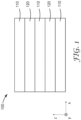
- the multilayer film 200 includes a plurality of polymeric third layers 130 arranged along the thickness direction with the first and second layers 110 and 120.
- the multilayer films 100 and 200 may have more layers than are schematically shown.
- the multilayer film includes 30 or fewer layers.
- the first and second layers number from 4 to 30, or 5 to 25, or 5 to 20 in total.
- a total of 5 layers are included and the thickness of the layers are in a range of 20 micrometers to 100 micrometers, or 35 micrometers to 175 micrometers, or 50 micrometers to 250 micrometers.
- a total of 7 layers are included and the thickness of the layers are in a range of 20 micrometers to 140 micrometers, or 25 micrometers to 175 micrometers, or 30 micrometers to 210 micrometers.
- a total of 13 layers are included and the thickness of the layers are in a range of 10 micrometers to 130 micrometers, or 15 micrometers to 195 micrometers, or 20 micrometers to 260 micrometers.
- the multilayer film is adapted to transmit and reflect light primarily by optical interference.
- the layers 110 and 120 may be interference layers arranged into optical repeat units having an optical thickness selected to reflect a desired wavelength of light.
- multilayer optical films including alternating layers can be used to provide desired reflection and transmission bands by suitable selection of layer materials for their refractive indices and suitable selection of layer thicknesses. Multilayer optical films and methods of making multilayer optical films are described in U.S. Pat. Nos. 5,882,774 (Jonza et al. ); 6,179,948 (Merrill et al. ); 6,783,349 (Neavin et al. ); 6,967,778 (Wheatley et al.
- Interference layers are typically less than about 500 nm thick.
- each of the first and second layer 110 and 120 has an average thickness less than 500 nm, or less than 400 nm, or less than 300 nm.
- each of the first and second layers 110 and 120 has an average thickness in a range of 10 nm to 200 nm or 10 nm to 100 nm.
- the number of layers can be fewer than, high than, or substantially higher than schematically illustrated in FIGS. 1-2 .
- the first and second layers number at least 50 in total.
- the total number of layers can be 50 to 1000, or 50 to 400, or 100 to 300, for example.
- a larger number of layers may be desired to provide a higher reflectivity and/or to reflect over a broader wavelength range, for example.
- a multilayer optical film has a thickness in a range of 30 to 250 micrometers, or 50 to 200 micrometers, for example.
- the average nanoparticle size can preferably be in the range of 4-20 nm.
- the preferred nanoparticle size is such that the nanoparticles have an average diameter of less than half of the nanocomposite layer thickness after the film is oriented.
- the nanoparticles may be present in the nanocomposite layer in a range of 2%-25%, 2%-20% or 2%-15% weight percent, for example.
- a multilayer film includes pluralities of first and second layers which provide a desired tear resistance and/or anti-shatter property, for example, and further includes further includes a plurality of alternating polymeric layers disposed on the pluralities of first and second layers.
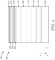
- the multilayer film of FIGS. 1-2 can provide a desired tear resistance and/or anti-shatter property and can optionally further include a plurality of alternating polymeric layers disposed on the illustrated layers to provide a desired reflectance in a desired wavelength range.
- An additional glass layer can be disposed on the plurality of alternating polymeric layers 210 and 220 opposite the layers 110 and 120.
- the multilayer film further includes a plurality of additional layers (e.g., corresponding to 110 and 120) is disposed between the additional glass layer and the alternating polymeric layers 210 and 220.
- the additional layers can be included for enhanced shatter resistance, for example.
- the multilayer film 300 is disposed on a glass layer, or between glass layers, for both strength (e.g., anti-shatter) and reflective properties (e.g., for a heads-up display and/or for solar infrared rejection).
- At least the first layers 110 include a nanocomposite of the present disclosure.
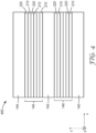
- one of the layers 210 and 220 and/or optional skin or protective boundary layers (not shown in FIG. 3 ; see, e.g., FIG. 4 ) formed with the layers 210 and 220 includes a nanocomposite of the present disclosure.
- FIG. 4 is a schematic cross-sectional view of multilayer film 400 including a first layer (any one of layers 140, 142 and 141 can be regarded as the first layer in the illustrated embodiment) and a plurality of alternating polymeric layers 210 and 220 disposed on the first layer.
- each of the alternating polymeric layers 210 and 220 has an average thickness of less than 500 nm or less than 400 nm.
- each of the layers 140, 142 and 144 has a thickness greater than 1 micrometer or greater than 2 micrometers.
- the first layer includes a nanocomposite of the present disclosure.
- two of the layers 140, 142 and 141 include a nanocomposite of the present disclosure.
- the first layer includes a nanocomposite of the present disclosure.
- the first layer can include at least one polymer and metal oxide nanoparticles dispersed in the at least one polymer, where the at least one polymer includes a first polymer including (meth)acrylic acid monomer units, and where the metal oxide nanoparticles are surface modified with a carboxylic acid silane surface modifying agent (e.g., according to Formula 1 described elsewhere).
- the at least one polymer further includes a second polymer different from the first polymer blended with the first polymer, where the second polymer includes (meth)acrylic acid monomer units.
- the second layer includes at least one polymer, where the at least one polymer of the second layer includes a first polymer including (meth)acrylic acid monomer units.
- the second layer further includes metal oxide nanoparticles dispersed in the at least one polymer of the second layer, where the metal oxide nanoparticles of the second layer are surface modified with a carboxylic acid silane surface modifying agent (e.g., according to Formula 1 described elsewhere).
- the at least one polymer of the second layer further includes a second polymer different from the first polymer of the second layer blended with the first polymer of the second layer, where the second polymer of the second layer includes (meth)acrylic acid monomer units.
- the alternating polymeric layers include alternating first (210) and second (220) interference layers.
- Each first interference layer includes at least one polymer (e.g., one polymer or a blend of first and second polymers), where the at least one polymer of the first interference layer includes a polymer including (meth)acrylic acid monomer units.
- each second interference layer includes an oriented polyester.
- each second interference layer can include a polyester including terephthalate monomer units and ethylene glycol monomer units.
- the first layers 210 are less birefringent than the second layers 220.
- the first layers 210 are substantially optically isotropic.
- the first layers 210 are lower index layers and the second layers 220 are higher index layers.
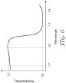
- FIG. 6 is a schematic plot of transmittance versus wavelength of a multilayer film according to some embodiments.
- the illustrated transmittance can be for substantially normally incident light.
- the multilayer film has an average transmittance of T1 over a wavelength range of ⁇ 1 to ⁇ 2, and an average transmittance of T2 over a wavelength range of ⁇ 3 to ⁇ 4.
- the wavelengths are such that ⁇ 1 ⁇ ⁇ 2 ⁇ ⁇ 3 ⁇ ⁇ 4.
- T1 is at least 60 percent, or at least 70 percent, or at least 80 percent, or at least 90 percent, when ⁇ 1 ⁇ 450 nm and ⁇ 2 ⁇ 650 nm.
- a multilayer film has a transmittance substantially different than schematically illustrated in FIG. 6 .
- a multilayer film can have one or more reflection bands between ⁇ 1 and ⁇ 2 for one polarization state or for each of two orthogonal polarization states.
- the nanocomposite layer may also be made by coating processes from aqueous dispersions on to a substrate such that the layer can be removed from the substrate.
- a nanocomposite includes at least one polymer and metal oxide nanoparticles dispersed in the at least one polymer of the nanocomposite.
- Each polymer can have a number average molecular weight of at least 10000 grams/mole.
- the at least one polymer of the nanocomposite includes a first polymer including (meth)acrylic acid monomer units (monomer units selected from the group consisting of methacrylic acid monomer units and acrylic acid monomer units).
- the metal oxide nanoparticles are surface modified with a surface modifying agent including a carboxylic acid silane of Formula 1 described elsewhere herein.
- the first polymer has a number average molecular weight of at least 12000 grams/mole or at least 15000 grams/mole.
- each polymer of the at least one polymer has a number average molecular weight of at least 12000 grams/mole or at least 15000 grams/mole.
- the at least one polymer can be a blend of first and second polymers, and each of the first and second polymers can have a number average molecular weight of at least 12000 grams/mole or at least 15000 grams/mole.
- the number average molecular mass of a polymer can be determined by gel permeation chromatography (GPC). Polymer characterization by GPC systems is well known.
- the Viscotek TDAmax (Malvern Panalytical, a part of Spectris plc).
- This system is equipped with multiple detectors for determination of molecular weight. Absolute molecular weight of small polymers can be measured using a right angle light scattering detector, direct output of absolute molecular weight of polymers without extrapolation can be obtained using low angle light scattering. Additional detectors can be used to assess information concerning polymer structure, for example branching using intrinsic viscosity detector and information concerning copolymer composition can be investigated using a photodiode array UV detector when UV absorbing components are present. Further details of this instrument can be found from the supplier.
- the first polymer, or each polymer of the at least one polymer has a number average molecular weight less than 100,000 grams/mole.
- the first polymer includes (meth)acrylic acid monomer units; ethylene monomer units, propylene monomer units, or a combination of ethylene and propylene monomer units; and at least one alkyl (meth)acrylate monomer unit.
- the at least one polymer can be a blend of two or more (meth)acrylic polymers.
- a wide range of blends of (meth)acrylic polymers are suitable.
- suitable blends include blends of acrylic acid or methacrylic acid homopolymers with copolymers of acrylic acid or methacrylic acid and at least one additional monomer (e.g., selected from the group consisting of ethylene, propylene, alkyl(meth)acrylates, aryl(meth)acrylates, alkaryl(meth)acrylates, acrylonitrile, and carbon monoxide).
- the at least one polymer includes a second polymer different from the first polymer.
- the first and second polymers can be different by virtue of having different molecular weights, different acid content, different neutralization percent, different amounts of the same monomer units, and/or by being compositionally distinct, for example.
- the second polymer is compositionally distinct from the first polymer. Compositionally distinct in this context can be understood to mean that at least one of the first and second polymers has a least one type of monomer unit not present in the other of the first and second polymers.
- the first polymer can include two different monomer units (e.g., (meth)acrylic acid and either ethylene or propylene) and the second polymer can include a different third monomer unit (e.g., n-butyl acrylate or isobutyl acrylate) in addition to the two monomer units of the first polymer.
- Compositionally distinct includes different acid types (e.g., methacrylic acid monomer units versus acrylic acid monomer units) and different ion types (an ion at least partially neutralizing an ionomer can be considered to be part of the ionomer), for example.
- the second polymer can have a number average molecular weight of at least 10000 grams/mole, or at least 12000 grams/mole, or at least 15000 grams/mole.
- the second polymer includes (meth)acrylic acid monomer units. In some embodiments, the second polymer includes at least one monomer unit selected from the group consisting of ethylene, propylene, alkyl(meth)acrylates, aryl(meth)acrylates, alkaryl(meth)acrylates, acrylonitrile, and carbon monoxide. In some embodiments, the second polymer includes at least one monomer unit selected from the group consisting of ethylene and propylene.
- the second polymer further includes at least one monomer unit selected from the group consisting of n-butyl acrylate, isobutyl acrylate, isopropyl acrylate, n-propyl acrylate, ethyl acrylate, methyl acrylate, 2-ethylhexyl acrylate, iso-octyl acrylate and methyl methacrylate.
- the second polymer includes (meth)acrylic acid monomer units; ethylene monomer units, propylene monomer units, or a combination of ethylene and propylene monomer units; and at least one alkyl (meth)acrylate monomer unit.
- the content of (meth)acrylic acid monomer units in the first polymer, and optionally in the second polymer is greater than 12 weight percent. This has been found to help in dispersing the first polymer, and optionally the second polymer, in water. In some embodiments, the content of (meth)acrylic acid monomer units in the first and the second polymers is similar. This has been found to help the compatibility of the polymers and to improve optical properties, for example.
- the first polymer includes (meth)acrylic acid monomer units at a first weight percent w1
- the second polymer includes (meth)acrylic monomer units at a second weight percent w2.
- the nanocomposite is formed from an aqueous dispersion including the first and second polymers as described further elsewhere herein.
- each of w1 and w2 is greater than 12 weight percent, or greater than 13 weight percent, or greater than 14 weight percent, or greater than 15 weight percent.
- is less than 10 weight percent, or less than 9 weight percent, or less than 8 weight percent, or less than 7 weight percent, or less than 6 weight percent.
- is in a range of 0 to 10 weight percent or in a range of 0 to about 9 weight percent (e.g., 8.8 or 9 or 9.2 weight percent can be considered to be about 9 weight percent).
- each of the two polymers in dispersion includes two monomer units (e.g., a (meth)acrylic acid monomer unit and a second monomer unit such as ethylene or propylene)
- the acid content of either the first polymer (w1) or second polymer (w2) may be in a range greater than 27 weight percent, for example.
- may be up to 15 weight percent, for example.
- the first polymer is at least partially neutralized with nonmetallic cations.
- the first polymer can be at least partially neutralized with alkylammonium cations.
- the nanocomposite is formed from an aqueous dispersion as described further elsewhere herein.
- the first polymer in the aqueous dispersion, is at least partially neutralized with at least one nonvolatile neutralizing agent, or at least one volatile neutralizing agent, or a combination of volatile and nonvolatile neutralizing agents.
- the first polymer in the aqueous dispersion, is at least partially neutralized with nonvolatile amine cations, volatile amine cations (e.g., cations of dimethylethanolamine or ammonium cations), or a combination of volatile and nonvolatile amine cations.
- volatile amine cations e.g., cations of dimethylethanolamine or ammonium cations
- the first polymer can be at least partially neutralized with a combination of different types of cations (e.g., metallic and nonmetallic cations or any combinations of cations describe herein).
- the first polymer can be an at least partially neutralized ionomer prior to being dispersed in the aqueous dispersion.
- the ionomer is sufficiently neutralized that no additional neutralizing agents need to be added to the aqueous dispersion. In other embodiments, the ionomer is further at least partially neutralized by additional neutralizing agents added to the aqueous dispersion as described further elsewhere herein.
- Suitable aminosilanes can be obtained from commercial sources such as Gelest, Inc. (Morrisville, PA), Alfa Aesar (Ward Hill, MA), Millipore Sigma (Burlington, MA), and Momentive Performance Materials (Waterford, NY).
- a particularly suitable aminosilane is aminopropyltrimethoxysilane.
- organic solvents can be used. Suitable organic solvents include N,N-dimethylformamide (DMF) which can be obtained from commercial sources such as OmniSolv (Billerica, MA).
- DMF N,N-dimethylformamide
- the particle size is greater than 4 nm, greater than 5 nm, greater than 10 nm, or greater than 20 nm. In some embodiments, the particle size is less than 190 nm, less than 150 nm, less than 100 nm, less than 75 nm, or less than 50 nm.
- the nanoparticles have a size ranging from 4-190 nm, 4-100 nm, 4-75 nm, 10-50 nm, or 20-50 nm. For low haze, typical preferred ranges are from 4-100 nm, 4-75 nm, or 4-50 nm.
- a base may be added to the aqueous nanodispersion of surface unmodified metal oxide nanoparticles to maintain the pH in the desired range since the addition of the carboxylic acid silane solution of Formula 1 will tend to lower pH.
- the organic solvent is removed from of the solution of carboxylic acid silane in organic solvent prior to combining the carboxylic acid silane and aqueous nanodispersion of surface unmodified metal oxide nanoparticles.
- Aqueous nanodispersions of unmodified metal oxide nanoparticles may be prepared or, in some embodiments, aqueous nanodispersions of unmodified metal oxide nanoparticles may be obtained commercially.
- Suitable surface unmodified metal oxide nanoparticles include aqueous nanodispersions commercially available from Nalco Chemical Company (Naperville, IL) under the trade designation "Nalco Colloidal Silicas" such as products NALCO 2326, 1130, DVSZN002, 1142, 2327, 1050, DVSZN004, 1060, and 2329K; from Nissan Chemical America Corporation (Houston, TX) under the tradename SNOWTEX such as products ST-NXS, ST-XS, ST-S, ST-30, ST-40, ST-N40, ST-50, ST-XL, and ST-YL; from Nyacol Nano Technologies, Inc.
- the surface unmodified metal oxide nanoparticles may be dispersed in an aqueous solution with a pH in the range 8-12.
- the surface-modified metal oxide nanoparticles are used as a nanodispersion, and the particles are not isolated.
- Another aspect of the present disclosure involves the preparation of nanodispersions of surface-modified metal oxide nanoparticles without precipitation, gelation, agglomeration, or aggregation, where the metal oxide nanoparticles are surface modified with a carboxylic acid silane of Formula 1.
- a solvent exchange is performed on the aqueous nanodispersion of surface-modified metal oxide nanoparticles and organic solvent to remove the organic solvent.
- the reactor is open, under reflux conditions, and in other embodiments the reactor is closed and under pressure.
- the reactor is glass and in some embodiments the reactor is stainless steel.
- the nanocomposite includes at least 1% by weight of surface-modified metal oxide nanoparticles and no more than 70% by weight of surface-modified metal oxide nanoparticles.
- the surface-modified metal oxide nanoparticle concentration is from 5-60% by weight, or from 10-50% by weight.
- a lower loading of the nanoparticles may be used when the nanocomposite layer is used as the low index layer of a multilayer optical film.
- the nanoparticles may be present in the nanocomposite layer in a range of 2%-15% weight percent, for example.
- Additional additives may include flame retardants, thermal stabilizers, anti-slip agents, neutralizing agents, UV absorbers, light stabilizers, antioxidants, crosslinking agents, mold release agents, catalysts, colorants, anti-stat agents, defoamers, plasticizers, and other processing aids, for example.
- an aqueous dispersion can be used in forming the nanocomposite or ionomer layers without nanoparticles. It has been unexpectedly found that high molecular weight (meth)acrylic polymer(s) (e.g., number average molecular weight of at least 10000 grams/mole) can be dispersed in water (e.g., with suitable neutralizing agents) and that the resulting aqueous dispersion is useful in making a nanocomposite, for example, with desired mechanical and optical properties.
- an aqueous dispersion includes water; at least one polymer dispersed in the water; and metal oxide nanoparticles dispersed in the water.
- SA succinic anhydride
- a Teflon coated stir bar was added to the jug.
- DMF N, N-dimethylformamide
- AMINO-TMOS 3-aminopropyltrimethoxysilane
- the resulting dispersion was filtered through a 200 ⁇ m sock filter (Pall Corp., Port Washington, NY) and transferred to two 18.93 liter plastic lined metal pails.
- the process conditions along characterization results are detailed in Table 7.
- the pH of the resulting dispersion was 11.5.
- Particle size analysis indicated a bimodal dispersion of sizes of 23.25 nm and 140.5 nm.
- the dispersion was milky white with a measured haze of 81.6%. Similar values of dried weights of unfiltered and filtered dispersions give an indication that the elastomer is fully dispersed. Table 4.
- Dispersion D34 illustrates preparation of an ionic elastomer blend dispersion in an open (atmospheric) reactor.
- the mass of each component is shown in Table 10.
- Deionized water was placed in a two liter cylindrical clear glass reactor (Ace Glass, Vineland, NJ).
- Coatings C1-C12 illustrate formulation of transparent ionic elastomer coatings.
- Each dispersion was coated onto an unprimed PET substrate film in a continuous roll-to-roll process where the dispersion was metered through a slot die onto a moving web.
- the ionic elastomer dispersion was metered by a metering pump and a mass flow meter. Volumetric flowrate for each coating formulation is given in Table 16.
- the volatile components of the coating formulation i.e. ionic elastomer dispersion
- the temperatures of each zone were 65.6°C, 79.4°C, and 135°C, respectively, from entrance to exit of the oven with each oven section nominally 3.05 m in length.
- Table 17 shows characterization results including coating thickness of 10 micrometers nominally, and visible transmission of greater than 93% and haze less than 1%. It is noted that that the optical characterization includes the PET substrate as well as the coating. The 75 ⁇ m PET substrate for all Coatings C1-C78 had a transmission of 91.9%, Haze of 00.65%, and Clarity of 99.9%. Table 16.
- Dispersion D42 illustrates preparation of a silica nanoparticle dispersion where the nanoparticle surface is modified with a carboxylic acid functionality.
- the carboxylic acid functionality is pursued to establish compatibility between the nanoparticle and (meth)acrylic acid elastomer.
- 49.33 kilograms of aqueous colloidal silica dispersion (NALCO 2327) was placed in a 2.67 liter stainless steel reactor. Agitation was initiated. 15.58 kg of ACID SILANE SURFACE AGENT SOLUTION was added to the reactor. The contents of the reactor were heated to 80°C. Upon reaching 80°C, the reactor was sealed, and the contents of the reactor maintained at 80°C with continuous agitation for 24 hours.
- Nanoparticle Dispersion DISPERSION NALCO 2327 (g) DI H 2 O (g) ACID SILANE Solution (g) SiO 2 (w%) pH D41 400 318 133 19.3 5.5 D42 49328 - 15581 31.3 5.5
- Film F16 illustrates an illustrates an ionic elastomer nanocomposite film with neutralization during melt processing.
- Film 17 illustrates use of a different neutralizing agent in the dispersion and melt processed film.
- Table 35 Ionic Elastomer Nanocomposite Film Material SiO 2 (w%) Elastomer (w%)
- ELASTOMER NANOCOMPOSITE PRIMACOR 5980i 40 60 C57 (g) 12.5 25.0 37.5 50.0 C58 (g) 25.0 25.0 NUCREL 960 40 60 C59 (g) 12.5 25.0 37.5 50.0
- ELASTOMER PRIMACOR 5980i 100 (g) 37.5 25.0 12.5 25.0 25.0 NUCREL 960 100 (g) 37.5 25.0 12.5 NEUTRALIZING AGENT KOH (g) 4.8 Press Temperature (°C) 125 125 125 175 125 125 125 125 125 125
- Films F22-F43 illustrate preparation of ionic elastomer nanocomposite blend films by a melt-process.
- Films F22-F43 were processed in the same manner as Films F1-F11. That is, an ionic elastomer nanocomposite coating was separated from the PET substrate film and melt-processed.
- the nanocomposite coating was melt-processed with a second (meth)acrylic acid elastomer different from that of the coating to form an ionic elastomer nanocomposite blend film.
- Composition details and hot press temperatures are given in Tables 37 and 38. Characterization results in Table 39 show visible transmission greater than 91% and a range of haze values from 2.9 to 26.6%.
- the high haze values 10.1-26.6% correlate with higher acid difference between the (meth)acrylic elastomers of the blend.
- Optical characterization showed that transparent ionic elastomer nanocomposites may be achieved with higher acid difference by melt processing than is accessible by dispersing and coating alone.
- TGA results on Films F38-F41 correlate well with calculated nanoparticle loading. The TGA results provide technical support not only for the melt-processed nanocomposite blend films but also for the coated nanocomposite films from which they were derived. Table 37.
- Films F44-F48 further illustrate ionic elastomer nanocomposite blend films by a melt-process.
- Films F44-F48 were processed in the same manner as Films F23-F43. That is, an ionic elastomer nanocomposite coating was separated from the PET substrate film and melt-processed with a second (meth)acrylic acid elastomer to form an ionic elastomer nanocomposite blend.
- the second ionic elastomer is a neutralized terpolymer which was found not to be dispersible in water but may be readily melt-processed. Composition details are given in Table 40 along with hot press temperatures.
- Film thickness was measured using a digital indicator model H0530E (Mitutoyo America Corporation, Aurora, IL).
- TGA Thermal Gravimetric Analysis
- Nanoparticle concentration in the melt-processed nanocomposite films was measured by TGA.
- a Model TGA Q500 (TA Instruments, New Castle, DE) was used.
- a 5 milligram sample of nanocomposite film or nanocomposite blend film was placed on a platinum pan that was previously tared by the instrument.
- the nanoparticle concentration was determined as the final weight in the sample after heating from 35°C to 700°C at 20°C/min.
- SA succinic anhydride
- a Teflon coated stir bar was added to the jug.
- DMF N, N-dimethylformamide
- AMINO-TMOS 3-aminopropyltrimethoxysilane
- SURLYN 9120 27.76 kilograms of deionized water was placed in a 37.85 liter stainless steel reactor. 5.11 kilograms of SURLYN 9120 in pellet form was added to the reactor to achieve a 15 weight percent elastomer dispersion. SURLYN 9120 is a pre-neutralized (meth)acrylic acid elastomer with 38% neutralization with Zn ++ . Agitation was initiated at 30 rpm. 1.20 kilograms of NaOH SOLUTION (PREPARATORY EXAMPLE 1) was added to the reactor. Agitation was increased to 120 rpm. The reactor was sealed to allow processing at higher temperatures and prevent loss of materials. Heat was initiated to a set point temperature of 150°C.
- aqueous colloidal silica dispersion (NALCO 2327) was placed in a 75.71 liter stainless steel reactor. Agitation was initiated. 15.58 kilograms of ACID SILANE SOLUTION (PREPARATORY EXAMPLE 2) was added to the reactor. The contents of the reactor were heated to 80°C. Upon reaching 80°C, the reactor was sealed, and the contents of the reactor maintained at 80°C with continuous agitation for 24 hours. After 24 hours, the contents of the reactor were cooled and filtered with a 50 ⁇ m filter and transferred to two 18.93 liter plastic lined metal drums. The pH of the nanoparticle dispersion was 5.5 and the nanoparticle concentration was calculated to be 31.3 wt%.
- SILICA NANODISPERSION PREPARATORY EXAMPLE 4
- a Teflon coated stir bar was added to the jar.
- the jar was placed on a stir plate and agitation initiated.
- the contents of the jar were mixed for 20 minutes and then the stir bar was removed from the jar.
- the pH of the nanoparticle dispersion was 10.0 and the nanoparticle concentration was calculated to be 30.6 wt%.
- TGA was used to measure nanoparticle concentration in the nanocomposite film.
- the TGA result of 13.43 w% correlates well with the calculated 10 w% nanoparticle concentration. It is noted that the metal ions will increase the TGA result.
- Table 4. Characterization of Ionic Elastomer Nanocomposite Film PE Ionomer SiO 2 (w%) Acid (w%) Ion Neutralization (%) SiO 2 (w%) TGA 1 Thickness (mil) T (%) H (%) C (%) 7 SURLYN 9120 10 19 Na + , Zn ++ 38 13.43 6.3 93.4 3.2 91.5 1 TGA designates SiO 2 content of nanocomposite measured by TGA
- PROPHETIC EXAMPLE 1 IONIC ELASTOMER NANOCOMPOSITE
- PROPHETIC EXAMPLE 1 illustrates continuous compounding of an ionic elastomer nanocomposite.
- IONIC ELASTOMERNANOCOMPOSITE COATING PREPARATORY EXAMPLE 6
- SURLYN 9120 is fed to the same extruder at a rate of 6 kg/hr.
- a strand die is attached to the end of the extruder.
- the extrudate in the form of a strand is passed through a water bath at the end of which was a pelletizer which cuts the ionic elastomer nanocomposite strand into pellets.
- PROPHETIC EXAMPLE 2 illustrates a coextruded 5-layer A:B:A:B:A cast web where the center and two outer A layers are a thermoplastic such as PET and the two inner B layers are an ionic elastomer nanocomposite.
- the two extruders feed to a feedblock designed to generate the 5-layer A:B:A:B:A layer structure and die are at 271°C.
- the multilayer extrudate is cast onto a chill roll with the aid of electrostatic pinning and is wound on a winder.
- the feedrates and cast wheel speeds are adjusted to achieve a cast web thickness is nominally 500 - 2000 micrometers.
- a 100 mm by 100 mm piece of 5-layer cast web of PROPHETIC EXAMPLE 2 is oriented using a KARO IV laboratory batch orientation (Bruckner Maschinenbau GMbH & Co KG, Siegsdorf, Germany).
- the cast web is loaded into the orienter.
- the cast web is preheated for 1 minute at the draw temperature between 95-120°C.
- the cast web is stretched at a rate of 20%/second.
- the draw ratio is between 2.5 x 2.5 and 4.0 x 4.0 (MD x TD).
- the oriented film is between 31 and 162 micrometers thick. Based on the description above it is well known that continuous roll to roll film of a desired thickness can be made in process where thick multilayer film is cast and then oriented in a tenter to produce rolls of film for example with a thickness of 150 ⁇ m.
- PROPHETIC EXAMPLE 4 ORIENTED MULTILAR FILM WITH COATING
- PROPHETIC EXAMPLE 6 MULTILAYER FILM ARTICLE
- a two glass layer construction with the glass layers bonded together with the multilayer optical film is made by the following process.
- a first 15 cm x 15 cm soda lime glass layer approximately 3 mm in thickness is provided.
- a few drops of deionized water are placed onto the glass and one side of the multilayer optical film with ionic elastomer skins is wet down to the glass.
- a squeegee is used to squeeze out and remove excess DI water between the glass and the nanocomposite layer.
- the film is allowed to sit at room temperature for approximately 1 hour.
- the exposed ionic elastomer skin layer is bonded to a second 15cmx15 cm soda lime glass layer.
Landscapes
- Physics & Mathematics (AREA)
- General Physics & Mathematics (AREA)
- Optics & Photonics (AREA)
- Life Sciences & Earth Sciences (AREA)
- Engineering & Computer Science (AREA)
- Wood Science & Technology (AREA)
- Laminated Bodies (AREA)
Claims (15)
- Eine Mehrschichtfolie (100, 200, 300, 400, 500), die eine Mehrzahl von ersten Schichten (110) und polymeren zweiten Schichten (120) umfasst, die entlang einer Dickenrichtung der Mehrschichtfolie angeordnet sind, wobei die ersten und die zweiten Schichten unterschiedliche Zusammensetzungen aufweisen, jede erste Schicht aufweisend:mindestens ein Polymer, wobei das mindestens eine Polymer ein erstes Polymer, aufweisend (Meth)acrylsäuremonomereinheiten, aufweist; undMetalloxidnanoteilchen, die in dem mindestens einen Polymer dispergiert sind, wobei die Metalloxidnanoteilchen mit einem Oberflächenmodifizierungsmittel oberflächenmodifiziert sind, aufweisend ein Carbonsäuresilan der Formel 1:
 R1 eine C1 bis C10-Alkoxygruppe ist;R2 und R3 unabhängig ausgewählt sind aus der Gruppe bestehend aus C1 bis C10-Alkyl und C1 bis C10-Alkoxygruppen; undA eine Linkergruppe ist, ausgewählt aus der Gruppe bestehend aus C1 bis C10-Alkylen- oder Arylengruppen, C1 bis C10-Aralkylengruppen, C2 bis C16-Heteroalkylen- oder Heteroarylengruppen und amidenthaltenden C2 bis C16-Gruppen.
 - Die Mehrschichtfolie nach Anspruch 1, wobei jede zweite Schicht einen Polyester aufweist, aufweisend Terephthalatmonomereinheiten und Ethylenglykolmonomereinheiten.
- Die Mehrschichtfolie nach Anspruch 1, wobei jede der ersten und zweiten Schichten eine durchschnittliche Dicke von weniger als 500 nm aufweist und wobei die gesamte Anzahl der ersten und der zweiten Schichten mindestens 50 beträgt.
- Die Mehrschichtfolie nach Anspruch 3, die eine Spiegelfolie für sichtbares Licht, eine Spiegelfolie für Infrarot, ein reflektierender Polarisator oder ein optischer Kerbfilter ist.
- Die Mehrschichtfolie nach Anspruch 1, die eine Lichtdurchlässigkeit für im Wesentlichen senkrecht einfallendes, unpolarisiertes Licht von mindestens 80 Prozent aufweist.
- Die Mehrschichtfolie nach Anspruch 1, wobei sich die ersten und die zweiten Schichten entlang der Dickenrichtung abwechseln.
- Die Mehrschichtfolie nach Anspruch 1, ferner aufweisend eine Mehrzahl von polymeren dritten Schichten (130), die entlang der Dickenrichtung mit den ersten und zweiten Schichten angeordnet sind.
- Die Mehrschichtfolie nach Anspruch 1, ferner aufweisend eine Mehrzahl von abwechselnden Polymerschichten, die auf den Mehrzahlen der ersten und zweiten Schichten angeordnet sind.
- Die Mehrschichtfolie nach Anspruch 8 mit einer durchschnittlichen optischen Durchlässigkeit für im Wesentlichen senkrecht einfallendes unpolarisiertes Licht von mindestens 70 Prozent über einen Wellenlängenbereich, der sich von mindestens 450 nm bis 650 nm erstreckt, und einer durchschnittlichen optischen Durchlässigkeit für im Wesentlichen senkrecht einfallendes unpolarisiertes Licht von nicht mehr als 50 Prozent über einen Wellenlängenbereich, der sich von mindestens 900 nm bis 1000 nm erstreckt.
- Die Mehrschichtfolie nach Anspruch 1, wobei das mindestens eine Polymer ferner ein zweites Polymer aufweist, das sich von dem ersten Polymer unterscheidet und vermischt mit dem ersten Polymer ist, wobei das zweite Polymer (Meth)acrylsäuremonomereinheiten aufweist.
- Ein optischer Stapel (301), aufweisend eine Glasschicht (350) und die Mehrschichtfolie nach einem der Ansprüche 1 bis 10, die auf der Glasschicht angeordnet ist.
- Eine Mehrschichtfolie (100, 200, 300, 400, 500), aufweisend eine erste Schicht (110) und eine Mehrzahl von abwechselnden polymeren Schichten (210, 220), die auf der ersten Schicht angeordnet sind, die erste Schicht aufweisend:mindestens ein Polymer, wobei das mindestens eine Polymer ein erstes Polymer, aufweisend (Meth)acrylsäuremonomereinheiten, aufweist; undMetalloxidnanoteilchen, die in dem mindestens einen Polymer dispergiert sind, wobei die Metalloxidnanoteilchen mit einem Oberflächenmodifizierungsmittel oberflächenmodifiziert sind, aufweisend ein Carbonsäuresilan der Formel 1:
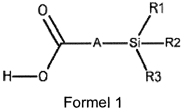 R1 eine C1 bis C10-Alkoxygruppe ist;R2 und R3 unabhängig ausgewählt sind aus der Gruppe bestehend aus C1 bis C10-Alkyl und C1 bis C10-Alkoxygruppen; undA eine Linkergruppe ist, ausgewählt aus der Gruppe bestehend aus C1 bis C10-Alkylen- oder Arylengruppen, C1 bis C10-Aralkylengruppen, C2 bis C16-Heteroalkylen- oder Heteroarylengruppen und amidenthaltenden C2 bis C16-Gruppen.
 - Die Mehrschichtfolie nach Anspruch 12, ferner aufweisend eine zweite Schicht (120), wobei mindestens eine Untermehrzahl der Mehrzahl von abwechselnden polymeren Schichten zwischen den ersten und zweiten Schichten angeordnet ist, die zweite Schicht aufweisend mindestens ein Polymer, wobei das mindestens eine Polymer der zweiten Schicht ein erstes Polymer, aufweisend (Meth)acrylsäuremonomereinheiten, aufweist.
- Die Mehrschichtfolie nach Anspruch 13, wobei die zweite Schicht ferner aufweist:
Metalloxidnanoteilchen, die in dem mindestens einen Polymer der zweiten Schicht dispergiert sind, wobei die Metalloxidnanoteilchen der zweiten Schicht mit einem oberflächenmodifizierenden Mittel aus Carbonsäuresilan oberflächenmodifiziert sind. - Die Mehrschichtfolie nach Anspruch 12, wobei die abwechselnden polymeren Schichten abwechselnde erste und zweite Interferenzschichten aufweisen, jede erste Interferenzschicht aufweisend mindestens ein Polymer, wobei das mindestens eine Polymer der ersten Interferenzschicht ein Polymer, aufweisend (Meth)acrylsäuremonomereinheiten, aufweist, jede zweite Interferenzschicht einen orientierten Polyester aufweist.
Applications Claiming Priority (2)
| Application Number | Priority Date | Filing Date | Title |
|---|---|---|---|
| US202062967440P | 2020-01-29 | 2020-01-29 | |
| PCT/IB2021/050547 WO2021152446A1 (en) | 2020-01-29 | 2021-01-25 | Multilayer film |
Publications (3)
| Publication Number | Publication Date |
|---|---|
| EP4096925A1 EP4096925A1 (de) | 2022-12-07 |
| EP4096925A4 EP4096925A4 (de) | 2024-03-13 |
| EP4096925B1 true EP4096925B1 (de) | 2025-04-09 |
Family
ID=77078622
Family Applications (1)
| Application Number | Title | Priority Date | Filing Date |
|---|---|---|---|
| EP21747741.3A Active EP4096925B1 (de) | 2020-01-29 | 2021-01-25 | Mehrschichtige folie |
Country Status (5)
| Country | Link |
|---|---|
| US (1) | US20230057101A1 (de) |
| EP (1) | EP4096925B1 (de) |
| JP (1) | JP7668805B2 (de) |
| KR (1) | KR20220133929A (de) |
| WO (1) | WO2021152446A1 (de) |
Families Citing this family (3)
| Publication number | Priority date | Publication date | Assignee | Title |
|---|---|---|---|---|
| US12362453B2 (en) * | 2021-07-21 | 2025-07-15 | Molex, Llc | Solar mitigation solutions for electronic equipment |
| WO2024128418A1 (ko) * | 2022-12-15 | 2024-06-20 | (주)바이오스마트 | 글라스 바디를 갖는 금속 카드 및 그 제조 방법 |
| CN116430498B (zh) * | 2023-03-03 | 2024-04-16 | 哈尔滨工业大学 | 一种光谱选择性低发射率的红外隐身涂层及其制备方法和应用 |
Family Cites Families (18)
| Publication number | Priority date | Publication date | Assignee | Title |
|---|---|---|---|---|
| US5415942A (en) * | 1993-11-04 | 1995-05-16 | E. I. Du Pont De Nemours And Company | Glass/plastic laminate structures for glazing applications |
| US5882774A (en) * | 1993-12-21 | 1999-03-16 | Minnesota Mining And Manufacturing Company | Optical film |
| US6083617A (en) * | 1995-04-13 | 2000-07-04 | Toray Industries, Inc. | Polyester composition and films produced therefrom |
| JP2002241583A (ja) | 2001-02-14 | 2002-08-28 | Sumitomo Bakelite Co Ltd | エポキシ樹脂組成物及び半導体装置 |
| JP2008105919A (ja) * | 2006-10-27 | 2008-05-08 | Hakuto Co Ltd | ポリマー被覆シリカ |
| JP6094271B2 (ja) * | 2012-03-05 | 2017-03-15 | 味の素株式会社 | 感光性樹脂組成物 |
| EP2695918A1 (de) | 2012-08-07 | 2014-02-12 | 3M Innovative Properties Company | Beschichtungszusammensetzung zur Vermeidung und/oder zum Entfernen von Kalkablagerungen und/oder Seifenschaum |
| JP2014071419A (ja) | 2012-10-01 | 2014-04-21 | Konica Minolta Inc | 光学フィルム及び光学フィルムの製造方法 |
| JP6454954B2 (ja) * | 2013-07-17 | 2019-01-23 | 東レ株式会社 | 組成物、これを用いた反射防止層およびその形成方法、ならびにそれを有するガラスおよび太陽電池モジュール |
| JP6902822B2 (ja) | 2014-11-14 | 2021-07-14 | 日鉄ケミカル&マテリアル株式会社 | タッチパネル絶縁膜・保護膜形成用の感光性樹脂組成物、並びにこれを用いた硬化膜及びタッチパネル |
| CN108026394B (zh) * | 2015-07-29 | 2021-02-19 | 3M创新有限公司 | 包含二氧化硅纳米粒子和官能硅烷化合物的防污组合物及其涂覆制品 |
| JP6705680B2 (ja) | 2016-03-30 | 2020-06-03 | 株式会社神戸製鋼所 | 非縮合型熱可塑性樹脂接着用化成処理金属板及びそれを用いた複合部材 |
| JP6809838B2 (ja) | 2016-08-08 | 2021-01-06 | スリーエム イノベイティブ プロパティズ カンパニー | アクリル系感圧接着剤、その製造方法、及びマーキングフィルム |
| JP2019019232A (ja) | 2017-07-18 | 2019-02-07 | 第一工業製薬株式会社 | 酸化ジルコニウム粒子分散体組成物およびその硬化物 |
| JP2019183044A (ja) * | 2018-04-13 | 2019-10-24 | Jnc株式会社 | 熱硬化性樹脂組成物、これを用いたインクジェットインク、硬化膜、硬化膜付き基板および電子部品 |
| CN112513196B (zh) * | 2018-07-30 | 2023-01-10 | 3M创新有限公司 | 透明的弹性体纳米复合材料共混物 |
| CN112513164B (zh) * | 2018-07-30 | 2023-04-21 | 3M创新有限公司 | 透明的弹性体纳米复合材料 |
| WO2020225703A1 (en) * | 2019-05-09 | 2020-11-12 | 3M Innovative Properties Company | Flexible hardcoat |
-
2021
- 2021-01-25 US US17/795,654 patent/US20230057101A1/en active Pending
- 2021-01-25 WO PCT/IB2021/050547 patent/WO2021152446A1/en not_active Ceased
- 2021-01-25 EP EP21747741.3A patent/EP4096925B1/de active Active
- 2021-01-25 KR KR1020227029237A patent/KR20220133929A/ko active Pending
- 2021-01-25 JP JP2022545985A patent/JP7668805B2/ja active Active
Also Published As
| Publication number | Publication date |
|---|---|
| EP4096925A4 (de) | 2024-03-13 |
| US20230057101A1 (en) | 2023-02-23 |
| JP2023511712A (ja) | 2023-03-22 |
| WO2021152446A1 (en) | 2021-08-05 |
| EP4096925A1 (de) | 2022-12-07 |
| KR20220133929A (ko) | 2022-10-05 |
| JP7668805B2 (ja) | 2025-04-25 |
Similar Documents
| Publication | Publication Date | Title |
|---|---|---|
| EP4096925B1 (de) | Mehrschichtige folie | |
| US12319794B2 (en) | Nanocomposites | |
| CN102985471B (zh) | 具有吸热性和改善的色彩特性的聚合物组合物 | |
| CA2399488C (en) | Ir-absorbing compositions | |
| EP2979862B1 (de) | Polycarbonatharzlaminat | |
| TWI510578B (zh) | 具有熱吸收性質和增進之色彩性質的聚合物組成物 | |
| US7074351B2 (en) | IR-absorbing compositions | |
| EP1550699A1 (de) | Thermoplastharzzusammensetzung und formkörper daraus | |
| AU2007360455B2 (en) | Masterbatch with high heat resistance, heat-ray-shielding transparent molded resin, and heat-ray-shielding transparent layered product | |
| JP4632094B2 (ja) | 高耐熱性マスターバッチの製造方法、熱線遮蔽透明樹脂成形体、並びに熱線遮蔽透明積層体 | |
| CN104144978B (zh) | 具有吸热性能的聚合物组合物 | |
| JP5257626B2 (ja) | 高耐熱性マスターバッチ、熱線遮蔽透明樹脂成形体、並びに熱線遮蔽透明積層体 | |
| CN101679650A (zh) | 热线屏蔽用聚酯膜及热线屏蔽用聚酯膜层压体 | |
| JP2025060675A (ja) | 透明エラストマーナノ複合体ブレンド | |
| CN108026358A (zh) | 聚酯树脂组合物、包含该树脂组合物的光反射体用元件和光反射体 | |
| JP4873790B2 (ja) | 紫外線遮蔽フィルム | |
| JP2010189482A (ja) | 有機無機複合組成物、成形体および光学部品 |
Legal Events
| Date | Code | Title | Description |
|---|---|---|---|
| STAA | Information on the status of an ep patent application or granted ep patent |
Free format text: STATUS: THE INTERNATIONAL PUBLICATION HAS BEEN MADE |
|
| PUAI | Public reference made under article 153(3) epc to a published international application that has entered the european phase |
Free format text: ORIGINAL CODE: 0009012 |
|
| STAA | Information on the status of an ep patent application or granted ep patent |
Free format text: STATUS: REQUEST FOR EXAMINATION WAS MADE |
|
| 17P | Request for examination filed |
Effective date: 20220801 |
|
| AK | Designated contracting states |
Kind code of ref document: A1 Designated state(s): AL AT BE BG CH CY CZ DE DK EE ES FI FR GB GR HR HU IE IS IT LI LT LU LV MC MK MT NL NO PL PT RO RS SE SI SK SM TR |
|
| DAV | Request for validation of the european patent (deleted) | ||
| DAX | Request for extension of the european patent (deleted) | ||
| A4 | Supplementary search report drawn up and despatched |
Effective date: 20240212 |
|
| RIC1 | Information provided on ipc code assigned before grant |
Ipc: G02B 1/14 20150101ALI20240206BHEP Ipc: B32B 27/32 20060101ALI20240206BHEP Ipc: B32B 27/30 20060101ALI20240206BHEP Ipc: B32B 27/20 20060101AFI20240206BHEP |
|
| GRAP | Despatch of communication of intention to grant a patent |
Free format text: ORIGINAL CODE: EPIDOSNIGR1 |
|
| STAA | Information on the status of an ep patent application or granted ep patent |
Free format text: STATUS: GRANT OF PATENT IS INTENDED |
|
| INTG | Intention to grant announced |
Effective date: 20241112 |
|
| P01 | Opt-out of the competence of the unified patent court (upc) registered |
Free format text: CASE NUMBER: APP_2107/2025 Effective date: 20250113 |
|
| GRAS | Grant fee paid |
Free format text: ORIGINAL CODE: EPIDOSNIGR3 |
|
| P01 | Opt-out of the competence of the unified patent court (upc) registered |
Free format text: CASE NUMBER: APP_2107/2025 Effective date: 20250113 |
|
| GRAA | (expected) grant |
Free format text: ORIGINAL CODE: 0009210 |
|
| STAA | Information on the status of an ep patent application or granted ep patent |
Free format text: STATUS: THE PATENT HAS BEEN GRANTED |
|
| AK | Designated contracting states |
Kind code of ref document: B1 Designated state(s): AL AT BE BG CH CY CZ DE DK EE ES FI FR GB GR HR HU IE IS IT LI LT LU LV MC MK MT NL NO PL PT RO RS SE SI SK SM TR |
|
| REG | Reference to a national code |
Ref country code: GB Ref legal event code: FG4D |
|
| REG | Reference to a national code |
Ref country code: CH Ref legal event code: EP |
|
| REG | Reference to a national code |
Ref country code: DE Ref legal event code: R096 Ref document number: 602021028935 Country of ref document: DE |
|
| REG | Reference to a national code |
Ref country code: IE Ref legal event code: FG4D |
|
| REG | Reference to a national code |
Ref country code: NL Ref legal event code: MP Effective date: 20250409 |
|
| PG25 | Lapsed in a contracting state [announced via postgrant information from national office to epo] |
Ref country code: NL Free format text: LAPSE BECAUSE OF FAILURE TO SUBMIT A TRANSLATION OF THE DESCRIPTION OR TO PAY THE FEE WITHIN THE PRESCRIBED TIME-LIMIT Effective date: 20250409 |
|
| REG | Reference to a national code |
Ref country code: AT Ref legal event code: MK05 Ref document number: 1783205 Country of ref document: AT Kind code of ref document: T Effective date: 20250409 |
|
| PG25 | Lapsed in a contracting state [announced via postgrant information from national office to epo] |
Ref country code: ES Free format text: LAPSE BECAUSE OF FAILURE TO SUBMIT A TRANSLATION OF THE DESCRIPTION OR TO PAY THE FEE WITHIN THE PRESCRIBED TIME-LIMIT Effective date: 20250409 Ref country code: PT Free format text: LAPSE BECAUSE OF FAILURE TO SUBMIT A TRANSLATION OF THE DESCRIPTION OR TO PAY THE FEE WITHIN THE PRESCRIBED TIME-LIMIT Effective date: 20250811 Ref country code: FI Free format text: LAPSE BECAUSE OF FAILURE TO SUBMIT A TRANSLATION OF THE DESCRIPTION OR TO PAY THE FEE WITHIN THE PRESCRIBED TIME-LIMIT Effective date: 20250409 |
|
| REG | Reference to a national code |
Ref country code: LT Ref legal event code: MG9D |
|
| PG25 | Lapsed in a contracting state [announced via postgrant information from national office to epo] |
Ref country code: GR Free format text: LAPSE BECAUSE OF FAILURE TO SUBMIT A TRANSLATION OF THE DESCRIPTION OR TO PAY THE FEE WITHIN THE PRESCRIBED TIME-LIMIT Effective date: 20250710 Ref country code: NO Free format text: LAPSE BECAUSE OF FAILURE TO SUBMIT A TRANSLATION OF THE DESCRIPTION OR TO PAY THE FEE WITHIN THE PRESCRIBED TIME-LIMIT Effective date: 20250709 |
|
| PG25 | Lapsed in a contracting state [announced via postgrant information from national office to epo] |
Ref country code: PL Free format text: LAPSE BECAUSE OF FAILURE TO SUBMIT A TRANSLATION OF THE DESCRIPTION OR TO PAY THE FEE WITHIN THE PRESCRIBED TIME-LIMIT Effective date: 20250409 |
|
| PG25 | Lapsed in a contracting state [announced via postgrant information from national office to epo] |
Ref country code: BG Free format text: LAPSE BECAUSE OF FAILURE TO SUBMIT A TRANSLATION OF THE DESCRIPTION OR TO PAY THE FEE WITHIN THE PRESCRIBED TIME-LIMIT Effective date: 20250409 |
|
| PG25 | Lapsed in a contracting state [announced via postgrant information from national office to epo] |
Ref country code: HR Free format text: LAPSE BECAUSE OF FAILURE TO SUBMIT A TRANSLATION OF THE DESCRIPTION OR TO PAY THE FEE WITHIN THE PRESCRIBED TIME-LIMIT Effective date: 20250409 |
|
| PG25 | Lapsed in a contracting state [announced via postgrant information from national office to epo] |
Ref country code: AT Free format text: LAPSE BECAUSE OF FAILURE TO SUBMIT A TRANSLATION OF THE DESCRIPTION OR TO PAY THE FEE WITHIN THE PRESCRIBED TIME-LIMIT Effective date: 20250409 |
|
| PG25 | Lapsed in a contracting state [announced via postgrant information from national office to epo] |
Ref country code: RS Free format text: LAPSE BECAUSE OF FAILURE TO SUBMIT A TRANSLATION OF THE DESCRIPTION OR TO PAY THE FEE WITHIN THE PRESCRIBED TIME-LIMIT Effective date: 20250709 |
|
| PG25 | Lapsed in a contracting state [announced via postgrant information from national office to epo] |
Ref country code: IS Free format text: LAPSE BECAUSE OF FAILURE TO SUBMIT A TRANSLATION OF THE DESCRIPTION OR TO PAY THE FEE WITHIN THE PRESCRIBED TIME-LIMIT Effective date: 20250809 |
|
| PG25 | Lapsed in a contracting state [announced via postgrant information from national office to epo] |
Ref country code: LV Free format text: LAPSE BECAUSE OF FAILURE TO SUBMIT A TRANSLATION OF THE DESCRIPTION OR TO PAY THE FEE WITHIN THE PRESCRIBED TIME-LIMIT Effective date: 20250409 |
|
| REG | Reference to a national code |
Ref country code: DE Ref legal event code: R097 Ref document number: 602021028935 Country of ref document: DE |
|
| PG25 | Lapsed in a contracting state [announced via postgrant information from national office to epo] |
Ref country code: DK Free format text: LAPSE BECAUSE OF FAILURE TO SUBMIT A TRANSLATION OF THE DESCRIPTION OR TO PAY THE FEE WITHIN THE PRESCRIBED TIME-LIMIT Effective date: 20250409 Ref country code: SM Free format text: LAPSE BECAUSE OF FAILURE TO SUBMIT A TRANSLATION OF THE DESCRIPTION OR TO PAY THE FEE WITHIN THE PRESCRIBED TIME-LIMIT Effective date: 20250409 |
|
| PG25 | Lapsed in a contracting state [announced via postgrant information from national office to epo] |
Ref country code: CZ Free format text: LAPSE BECAUSE OF FAILURE TO SUBMIT A TRANSLATION OF THE DESCRIPTION OR TO PAY THE FEE WITHIN THE PRESCRIBED TIME-LIMIT Effective date: 20250409 |
|
| PG25 | Lapsed in a contracting state [announced via postgrant information from national office to epo] |
Ref country code: EE Free format text: LAPSE BECAUSE OF FAILURE TO SUBMIT A TRANSLATION OF THE DESCRIPTION OR TO PAY THE FEE WITHIN THE PRESCRIBED TIME-LIMIT Effective date: 20250409 |
|
| PG25 | Lapsed in a contracting state [announced via postgrant information from national office to epo] |
Ref country code: SK Free format text: LAPSE BECAUSE OF FAILURE TO SUBMIT A TRANSLATION OF THE DESCRIPTION OR TO PAY THE FEE WITHIN THE PRESCRIBED TIME-LIMIT Effective date: 20250409 |
|
| PG25 | Lapsed in a contracting state [announced via postgrant information from national office to epo] |
Ref country code: IT Free format text: LAPSE BECAUSE OF FAILURE TO SUBMIT A TRANSLATION OF THE DESCRIPTION OR TO PAY THE FEE WITHIN THE PRESCRIBED TIME-LIMIT Effective date: 20250409 |
|
| PLBE | No opposition filed within time limit |
Free format text: ORIGINAL CODE: 0009261 |
|
| STAA | Information on the status of an ep patent application or granted ep patent |
Free format text: STATUS: NO OPPOSITION FILED WITHIN TIME LIMIT |
|
| REG | Reference to a national code |
Ref country code: CH Ref legal event code: L10 Free format text: ST27 STATUS EVENT CODE: U-0-0-L10-L00 (AS PROVIDED BY THE NATIONAL OFFICE) Effective date: 20260218 |
|
| 26N | No opposition filed |
Effective date: 20260112 |
|
| PGFP | Annual fee paid to national office [announced via postgrant information from national office to epo] |
Ref country code: DE Payment date: 20251217 Year of fee payment: 6 |