EP4097527B1 - Kabelabdichtung mit mehreren konfigurationen - Google Patents
Kabelabdichtung mit mehreren konfigurationen Download PDFInfo
- Publication number
- EP4097527B1 EP4097527B1 EP21702495.9A EP21702495A EP4097527B1 EP 4097527 B1 EP4097527 B1 EP 4097527B1 EP 21702495 A EP21702495 A EP 21702495A EP 4097527 B1 EP4097527 B1 EP 4097527B1
- Authority
- EP
- European Patent Office
- Prior art keywords
- tower
- gel block
- gel
- base
- ports
- Prior art date
- Legal status (The legal status is an assumption and is not a legal conclusion. Google has not performed a legal analysis and makes no representation as to the accuracy of the status listed.)
- Active
Links
Images


Classifications
-
- H—ELECTRICITY
- H02—GENERATION; CONVERSION OR DISTRIBUTION OF ELECTRIC POWER
- H02G—INSTALLATION OF ELECTRIC CABLES OR LINES, OR OF COMBINED OPTICAL AND ELECTRIC CABLES OR LINES
- H02G15/00—Cable fittings
- H02G15/013—Sealing means for cable inlets
-
- G—PHYSICS
- G02—OPTICS
- G02B—OPTICAL ELEMENTS, SYSTEMS OR APPARATUS
- G02B6/00—Light guides; Structural details of arrangements comprising light guides and other optical elements, e.g. couplings
- G02B6/44—Mechanical structures for providing tensile strength and external protection for fibres, e.g. optical transmission cables
- G02B6/4439—Auxiliary devices
- G02B6/444—Systems or boxes with surplus lengths
- G02B6/4441—Boxes
- G02B6/4442—Cap coupling boxes
- G02B6/4444—Seals
-
- G—PHYSICS
- G02—OPTICS
- G02B—OPTICAL ELEMENTS, SYSTEMS OR APPARATUS
- G02B6/00—Light guides; Structural details of arrangements comprising light guides and other optical elements, e.g. couplings
- G02B6/44—Mechanical structures for providing tensile strength and external protection for fibres, e.g. optical transmission cables
- G02B6/4439—Auxiliary devices
- G02B6/4471—Terminating devices ; Cable clamps
- G02B6/44775—Cable seals e.g. feed-through
Definitions
- Telecommunications systems typically employ a network of telecommunications cables capable of transmitting large volumes of data and voice signals over relatively long distances.
- the telecommunications cables can include fiber optic cables, electrical cables, or combinations of electrical and fiber optic cables.
- a typical telecommunications network also includes a plurality of telecommunications enclosures integrated throughout the network of telecommunications cables.
- the telecommunications enclosures are adapted to house and protect telecommunications components such as splices, termination panels, power splitters and wavelength division multiplexers. It is often preferred for the telecommunications enclosures to be re-enterable.
- re-enterable means that the telecommunications enclosures can be reopened to allow access to the telecommunications components housed therein without requiring the removal and destruction of the telecommunications enclosures.
- certain telecommunications enclosures can include separate access panels that can be opened to access the interiors of the enclosures, and then closed to re-seal the enclosures.
- Other telecommunications enclosures take the form of elongated sleeves formed by wrap-around covers or half-shells having longitudinal edges that are joined by clamps or other retainers.
- Still other telecommunications enclosures include two half-pieces that are joined together through clamps, wedges or other structures.
- Telecommunications enclosures are typically sealed to inhibit the intrusion of moisture or other contaminants.
- Pressurized gel-type seals have been used to effectively seal the locations where telecommunications cables enter and exit telecommunications enclosures.
- Example pressurized gel-type seals are disclosed by document EP 0442941 B1 and document EP 0587616 B1 . Both of these documents disclose gel-type cable seals that are pressurized through the use of threaded actuators.
- Document US 6,046,406 discloses a cable seal that is pressurized through the use of an actuator including a cam lever. While pressurized cable seals have generally proven to be effective, improvements in this area are still needed.
- the invention relates to a telecommunications enclosure as defined in independent claim 1. Further embodiments are described in the dependent claims 2-15.
- inventive aspects can relate to individual features and to combinations of features. It is to be understood that both the forgoing general description and the following detailed description are exemplary and explanatory only and are not restrictive of the broad inventive concepts upon which the embodiments disclosed herein are based.
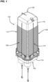
- the present disclosure is directed to a communications enclosure 100 (e.g., a telecommunications enclosure) extending along a length L from a first end 102 to a second end 104 ( FIG. 2 ).
- the enclosure 100 includes a housing 101 that defines a sealed interior.
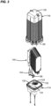
- a fiber optic organizer 140 ( FIG. 3 ) is disposed within the sealed interior.
- the first end 102 of the enclosure 100 is closed and the second end 104 of the enclosure 100 defines gel block ports 120 at each of which a cable sealing gel block 122 can be received. Cables pass through the cable sealing gel blocks 122 to enter the housing 101 and reach the fiber optic organizer 140.
- the fiber optic organizer 140 can be selectively mounted in one of multiple tower positions relative to the housing 101.
- the fiber optic organizer 140 is mountable to the housing in one of at least two different tower positions. In the first tower position, the tower is disposed between a first of the gel block ports and a second of the gel block ports. In the second tower position, the tower is disposed between the second gel block port and a third of the gel block ports that is different from the first gel block port. In certain examples, the fiber optic organizer 140 faces in different directions between the first and second tower positions.
- the housing 101 includes a dome 116 and a base 114.
- the dome 116 defines the first end 102 of the enclosure 100 and the base 114 defines the second end 104 of the enclosure. Accordingly, the base 114 defines the gel block ports 120.
- the dome 116 cooperates with the base 114 to define the sealed interior of the housing 101.
- a gasket is disposed between the base 114 and the dome 116 at a mating interface thereof. The gasket provides environmental sealing at the mating interface.
- the dome 116 has an open end 126 positioned opposite from a closed end 128.
- the base 114 mounts at the open end 126 of the dome 116 to close the open end 126 of the dome 116.
- the dome 116 and the base 114 are secured together by latches 105. In other examples, however, the dome 116 and base 114 are secured together by fasteners, a friction-fit, or securement techniques.
- the dome 116 and the base 114 have transverse cross-sectional shapes that are polygonal. In certain examples, the dome 116 and the base 114 have transverse cross-sectional shapes that are generally rectangular. In certain examples, the housing 101 has a width W extending from a first side 106 to a second side 108 ( FIG. 4 ) and a depth D extending from a third side 110 to a fourth side 112 ( FIG. 4 ). In certain examples, the transverse cross-sectional shapes of the dome 116 and the base 114 are generally square. In such examples, the width W is generally the same as the depth D. In other examples, the dome 116 and the base 114 have transverse cross-sectional shapes that are generally rounded (e.g., circular, oblong, etc.).
- the base 114 is a unitary (e.g., molded) piece.
- the base 114 includes a plate portion 123 through which the gel block ports 120 extend.
- sleeves 124 extend outwardly from the plate portion 123 to extend the lengths of the gel block ports 120.
- the plate portion 123 extends across the open end 126 of the dome 116 and the sleeves 124 extend outwardly from the plate portion 123 away from the dome 116.
- the sleeves 124 may define a lip on which the corresponding cable sealing gel block 122 seats when installed at the gel block port 120.
- the cable sealing gel block 122 can be otherwise secured at the gel block port 120 (e.g., using fasteners, friction-fit, or other attachment mechanisms).
- the sleeves 124 can detachably couple to the plate portion 123 and seals can be provided for sealing between the sleeves 124 and the plate portion 123.
- cover portions 121 are initially disposed at the gel block ports 120 to close the gel block ports 120 (e.g., see FIG. 5 ).
- the cover portions 121 inhibit cable sealing gel blocks 122 from being positioned within the gel block ports 120.
- the cover portions 121 inhibit dust or other particle contaminants from entering the housing 101 through the gel block ports 120.
- the cover portions 121 inhibit water or other liquids from entering the housing 101 through the gel block ports 120.
- Each of the cover portions 121 is individually removable from the respective gel block port 120 to enable installation of a cable sealing gel block 122 at the gel block port 120.
- the base 114 is a molded piece and the cover portions 121 are unitary with the molded piece.
- peripheries of the cover portions 121 may be perforated, scored, or otherwise seamed to facilitate removal of the cover portions 121.
- the cover portions 121 are punch out covers. In other examples, the cover portions 121 are removed by cutting.
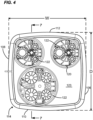
- the base 114 includes first, second, and third gel block ports 120a, 120b, 120c each adapted to receive a respective cable-sealing gel block 122.
- each of the first, second, and third gel block ports 120a-120c have a common transverse cross-sectional shape. In certain examples, the first, second and third gel block ports 120a-120c each have a circular transverse cross-sectional shape. In certain examples, the first, second and third gel block ports 120a-120c each have an oval transverse cross-sectional shape. In certain examples, the first, second and third gel block ports 120a-120c each have an otherwise oblong transverse cross-sectional shape.
- the base 114 can be divided into first, second, third and fourth quadrants Q1-Q4 by first and second perpendicular reference planes R1, R2 that intersect at a central longitudinal axis C of the housing 101 (e.g., see FIG. 5 ).
- first and second perpendicular reference planes R1, R2 that intersect at a central longitudinal axis C of the housing 101 (e.g., see FIG. 5 ).
- the first, second, third and fourth quadrants Q1-Q4 are sequentially positioned in a clockwise direction about the central longitudinal axis C of the housing 101.
- the first, second, and third gel block ports 120a, 120b, 120c also are positioned sequentially about the central longitudinal axis C of the housing 101 in a clockwise direction (e.g., see FIG. 5 ).
- the quadrants Q1-Q4 and gel block ports 120a-120c can be sequentially positioned in a counter-clockwise direction about the axis C.
- the first and second gel block ports 120a, 120b have the same transverse cross-sectional area while the third gel block port 120c has a different transverse cross-sectional area from the second gel block port 120b.
- the transverse cross-sectional area of the third gel block port 120c is at least 25 percent larger than the transverse cross-sectional area of the second gel block port 120b. In certain examples, the transverse cross-sectional area of the third gel block port 120c is at least 50 percent larger than the transverse cross-sectional area of the second gel block port 120b.
- the first gel block port 120a is located at least primary in the first quadrant Q1, the second gel block port 120b is located at least primarily in the second quadrant Q2, and the third gel block port 120c is located at least primarily in the third quadrant Q3.
- a gel block port 120 is primarily located in a quadrant if at least a majority of the transverse cross-sectional area of the gel block port 120 is contained within the boundaries of the quadrant.
- the first gel block port 120a is fully disposed within the first quadrant Q1 and the second gel block 120b is fully disposed within the second quadrant Q2.
- the third gel block port 120c is primarily disposed in the third quadrant Q3 while having portions extending into the second and fourth quadrants Q2, Q4 in FIG. 5 .
- the fourth quadrant Q4 is primarily void of gel block ports 120.
- a quadrant is primary void of gel block ports 120 is no gel block port 120 has at least a majority of its transverse cross-sectional area disposed within the boundaries of the quadrant.
- FIG. 6 illustrates an example cable sealing gel block 122 suitable for use with the enclosure 100 disclosed herein.
- the cable sealing gel block 122 includes a volume of gel 134 positioned axially between first and second gel pressurization structures 130, 132.
- Each of the gel pressurization structures 130, 132 defines one or more cable pass-through locations 136 that align with the one or more cable pass-through locations of the other pressurization structure 132, 130.
- An actuator 138 enables a user to move the pressurization structures 130, 132 towards each other to pressurize the volume of gel 134.
- the actuator 138 includes a threaded compression mechanism.
- the actuator 138 includes a camming compression mechanism.
- An example actuator suitable for use with the cable sealing gel block 122 is shown and described in U.S. Patent No. 9,948,082 .
- pressurizing the volume of gel 134 of the cable sealing gel block 122 e.g., using the actuator 138
- the volume of gel 134 also conforms about and seals about cables routed through the cable sealing gel block 122 during pressurization.
- the circumferential exterior of the volume of gel 134 unseals from the portion of the base 114 defining the gel block port 120, thereby allowing movement (e.g., removal) of the cable sealing gel block 122 relative to the gel block port 120.
- the first gel block port 120a is configured to receive a first cable sealing gel block 122a; the second gel block port 120b is adapted to receive a second cable sealing gel block 122b, and the third gel block port 120c is adapted to receive a third cable sealing gel block 122c.
- the third cable sealing gel block 122c has a larger transverse cross-sectional area as compared to the first cable sealing gel block 122a.
- the third cable sealing gel block 122b is adapted to receive and seal larger diameter cables as compared to the first cable sealing gel block 122a.
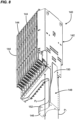
- a fiber optic organizer 140 mounts within the housing 101.
- the fiber optic organizer 140 includes a tower 142 and one or more fiber management trays 144 that are supported by the tower 142.
- the fiber management trays 144 are pivotally moveable relative to the tower 142.
- the tower 142 includes an upright portion 150 that extends from an attachment end 146 toward the trays 144.
- the upright portion 150 includes a support member 155 to which the management trays 144 mount (e.g., pivotally mount).
- the tower 142 also includes a lateral extension portion 152 that projects laterally outwardly from the upright portion 150 at the attachment end 146 of the tower 142.
- one or more of the fiber management trays 144 include splice trays for holding optical splices between optical fibers. In certain examples, one or more of the fiber management trays 144 are storage trays for holding excess fiber length. In certain examples, one or more of the fiber management trays 144 include optical splitter trays for holding optical power splitters, wave division multiplexers, optical taps, or other optical signal splitting devices.
- the tower 142 is mountable to the base 114 (e.g., to the plate portion 143) in either of a first tower position and a second tower position.
- the tower 142 is located to facilitate routing optical fibers from the first and second gel block ports 120a, 120b to the trays 144.
- the tower 142 is located to facilitate routing optical fibers from the second and third gel block ports 120b, 120c to the trays 144.
- the first tower position is located adjacent a different set of gel block ports 120 than the second tower position.
- the tower 142 faces in a different direction when in the first tower position compared to when in the second tower position.
- the first and second tower positions are offset about 90 degrees with respect to one another about the central longitudinal axis C of the housing 101 (e.g., compare FIGS. 9 and 10 ).
- the first tower position does not substantially overlap with the second tower position.
- the upright portion 150 of the tower 142 is positioned asymmetric relative to the base 114 in any of the tower positions. In certain examples, the upright portion 150 is positioned adjacent to a periphery of the base 114 when the tower 142 is mounted to the base 114 in any of the first and second tower positions. In certain examples, the upright portion 150 of the tower 142 is disposed adjacent the fourth side 112 of the base 114 when in the first tower position (see FIG. 9 ) and is disposed adjacent the first side 106 of the base 114 when in the second tower position (see FIG. 10 ).
- the tower 142 is mounted to the base 114 using one or more fasteners (e.g., screws, bolts, etc.). In other implementations, the tower 142 is mounted to the base 114 using latches. In still other implementations, the tower 142 can be friction-fit to the base 114.
- the first and second tower positions are indicated on the base 114.
- the base 114 may include fastener openings, latches, catch members, guide openings, pegs, or other mounting structures at both of the pre-defined tower positions to facilitate mounting the tower 142 to the base 114. In other implementations, however, the base 114 does not indicate the first and second tower positions.
- the tower 142 includes first and second fiber routing paths P1, P2 for routing fibers from an attachment end 146 of the tower 142 toward the trays 144 (e.g., see FIG. 8 ).
- the first routing path P1 is positioned adjacent to the first gel block port 120a and the second fiber routing path P2 is positioned adjacent to the second gel block port 120b when the tower 142 is mounted to the base 114 in the first tower position (e.g., see FIG. 9 ).
- the first routing path P1 is positioned adjacent to the second gel block port 120b and the second fiber routing path P2 is positioned adjacent to the third gel block port 120c when the tower 142 is mounted to the base 114 in the second tower position.
- the tower 142 includes a divider 148 for separating the first and second fiber routing paths P1, P2.
- the divider 148 is oriented between the first and second gel block ports 120a, 120b when the tower 142 is mounted to the base 114 in the first tower position.
- the divider 148 is oriented between the second and third gel block ports 120b, 120c when the tower 142 is mounted to the base 114 in the second tower position.
- the divider 148 includes a first divider portion 154 ( FIG. 3 ) on the upright portion 150 of the tower 142 and a second divider portion 156 ( FIG. 3 ) on the lateral extension portion 152 of the tower 142.
- the lateral extension portion 152 of the tower 142 and the second divider portion 156 of the divider 148 extend between the first and second gel block ports 120a, 120b when the tower 142 is mounted to the base 114 in the first tower position.
- the lateral extension portion 152 of the tower 142 and the second divider portion 156 of the divider 148 extend between the second and third gel block ports 120b, 120c when the tower 142 is mounted to the base 114 in the second tower position.
Landscapes
- Physics & Mathematics (AREA)
- General Physics & Mathematics (AREA)
- Optics & Photonics (AREA)
- Light Guides In General And Applications Therefor (AREA)
Claims (15)
- Telekommunikationsgehäuse, umfassend:ein Gehäuse (101), beinhaltend:eine Kuppel (116) mit einem offenen Ende (126), das einem geschlossenen Ende (128) gegenüberliegend angeordnet ist;eine Basis (114), die an dem offenen Ende der Kuppel montiert und zum Verschließen des offenen Endes der Kuppel konfiguriert ist, wobei die Basis einen ersten, einen zweiten und einen dritten Gelblockanschluss (120a, b, c) beinhaltet, die zum Aufnehmen von kabelabdichtenden Gelblöcken (122) geeignet sind, wobei zumindest der zweite und der dritte Gelblockanschluss unterschiedliche transversale Querschnittsflächen aufweisen; undeinen Lichtleitfaserorganisator (140), der innerhalb des Gehäuses montiert ist, wobei der Lichtleitfaserorganisator einen Turm (142) und eine Vielzahl von Lichtleitfaserverwaltungsablagen (144) beinhaltet, die von dem Turm getragen werden und in Bezug auf den Turm schwenkbar sind, wobei der Turm an der Basis in ersten und zweiten unterschiedlichen Turmpositionen montiert werden kann, wobei, wenn der Turm an der Basis in der ersten Turmposition montiert ist, der Turm zum Erleichtern der Verlegung von Lichtleitfasern von dem ersten und zweiten Gelblockanschluss zu der Vielzahl von Lichtleitfaserverwaltungsablagen angeordnet ist, und wobei, wenn der Turm an der Basis in der zweiten Turmposition montiert ist, der Turm zum Erleichtern der Verlegung von Lichtleitfasern von dem zweiten und dritten Gelblockanschluss zu der Vielzahl von Lichtleitfaserverwaltungsablagen angeordnet ist,dadurch gekennzeichnet, dassdie erste und die zweite Turmposition um 90 Grad zueinander um eine zentrale Längsachse des Gehäuses versetzt sind.
- Telekommunikationsgehäuse nach Anspruch 1, wobei der Turm einen ersten und einen zweiten Faserverlegungspfad (P1, P2) beinhaltet, die zum Verlegen von Fasern von einem Befestigungsende (146) des Turms in Richtung der Vielzahl von Lichtleitfaserverwaltungsablagen konfiguriert sind, wobei, wenn der Turm in der ersten Turmposition an der Basis montiert ist, der erste Faserverlegungspfad angrenzend an den ersten Gelblockanschluss angeordnet ist und der zweite Faserverlegungspfad angrenzend an den zweiten Gelblockanschluss angeordnet ist, und wobei, wenn der Turm in der zweiten Turmposition an der Basis montiert ist, der erste Faserverlegungspfad angrenzend an den zweiten Gelblockanschluss angeordnet ist und der zweite Faserverlegungspfad angrenzend an den dritten Gelblockanschluss angeordnet ist.
- Telekommunikationsgehäuse nach Anspruch 2, wobei der Turm einen Teiler (148) beinhaltet, der zum Trennen des ersten und des zweiten Faserverlegungspfads konfiguriert ist, wobei der Teiler zwischen dem ersten und dem zweiten Gelblockanschluss ausgerichtet ist, wenn der Turm in der ersten Turmposition an der Basis montiert ist, und wobei der Teiler zwischen dem zweiten und dem dritten Gelblockanschluss ausgerichtet ist, wenn der Turm in der zweiten Turmposition an der Basis montiert ist.
- Telekommunikationsgehäuse nach Anspruch 3, wobei der Turm einen aufrechten Abschnitt, der sich von einem Befestigungsende in Richtung der Vielzahl von Lichtleitfaserverwaltungsablagen erstreckt, und einen seitlichen Verlängerungsabschnitt (152) an dem Befestigungsende beinhaltet, wobei der seitliche Verlängerungsabschnitt von dem aufrechten Abschnitt seitlich nach außen vorsteht, wobei der Teiler einen ersten Teilerabschnitt (154) an dem aufrechten Abschnitt des Turms und einen zweiten Teilerabschnitt (156) an dem seitlichen Verlängerungsabschnitt des Turms beinhaltet.
- Telekommunikationsgehäuse nach Anspruch 4, wobei sich der seitliche Verlängerungsabschnitt des Turms und der zweite Teilerabschnitt des Teilers zwischen dem ersten und dem zweiten Gelblockanschluss erstrecken, wenn der Turm an der Basis in der ersten Turmposition montiert ist, und wobei sich der seitliche Verlängerungsabschnitt des Turms und der zweite Teilerabschnitt des Teilers zwischen dem zweiten und dem dritten Gelblockanschluss erstrecken, wenn der Turm an der Basis in der zweiten Turmposition montiert ist.
- Telekommunikationsgehäuse nach Anspruch 4 oder 5, wobei der aufrechte Abschnitt des Turms angrenzend an einen Umfang der Basis angeordnet ist, wenn er in der ersten und zweiten Turmposition an der Basis montiert ist.
- Telekommunikationsgehäuse nach einem der Ansprüche 1 bis 6, wobei die Querschnittsfläche des dritten Gelblockanschlusses um zumindest 25 Prozent größer ist als die Querschnittsfläche des zweiten Gelblockanschlusses.
- Telekommunikationsgehäuse nach einem der Ansprüche 1 bis 6, wobei die transversale Querschnittsfläche des dritten Gelblockanschlusses um zumindest 50 Prozent größer ist als die transversale Querschnittsfläche des zweiten Gelblockanschlusses.
- Telekommunikationsgehäuse nach einem der Ansprüche 1 bis 8, wobei die Basis durch erste und zweite senkrechte Referenzebenen, die sich an einer zentralen Längsachse des Gehäuses schneiden, in erste, zweite, dritte und vierte Quadranten unterteilt ist, wobei die ersten, zweiten, dritten und vierten Quadranten aufeinanderfolgend im Uhrzeigersinn oder entgegen dem Uhrzeigersinn um die zentrale Längsachse des Gehäuses angeordnet sind, wobei der erste Gelblockanschluss zumindest im Wesentlichen in dem ersten Quadranten angeordnet ist, der zweite Gelblockanschluss zumindest im Wesentlichen in dem zweiten Quadranten angeordnet ist und der dritte Gelblockanschluss zumindest im Wesentlichen in dem dritten Quadranten angeordnet ist.
- Telekommunikationsgehäuse nach Anspruch 9, wobei der vierte Quadrant im Wesentlichen frei von Gelblockanschlüssen ist.
- Telekommunikationsgehäuse nach einem der Ansprüche 1 bis 10, wobei die Kuppel und die Basis transversale Querschnittsformen aufweisen, die allgemein rechteckig oder allgemein quadratisch sind.
- Telekommunikationsgehäuse nach einem der Ansprüche 1 bis 11, wobei die Basis ein Formteil ist und wobei die Basis, wenn die Basis geformt ist, einteilige Abdeckungsabschnitte beinhaltet, die den ersten, zweiten und dritten Gelblockanschluss verschließen, wobei die einteiligen Abdeckungsabschnitte einzeln von dem ersten, zweiten und dritten Gelblockanschluss entfernt werden können, um die Installation der kabelabdichtenden Gelblöcke in dem ersten, zweiten und dritten Gelblockanschluss zu ermöglichen.
- Telekommunikationsgehäuse nach Anspruch 12, wobei die einteiligen Abdeckungsabschnitte ausgestanzte Abdeckungen sind oder durch Schneiden entfernt werden.
- Telekommunikationsgehäuse nach einem der Ansprüche 1 bis 13, wobei die kabelabdichtenden Gelblöcke jeweils eine erste und eine zweite Geldruckbeaufschlagungsstruktur, die Kabeldurchgangsstellen definieren, ein Gelvolumen, das axial zwischen der ersten und der zweiten Geldruckbeaufschlagungsstruktur angeordnet ist, und ein Stellglied beinhalten, das zum Drücken der ersten und der zweiten Geldruckbeaufschlagungsstruktur in axialer Richtung aufeinander zu konfiguriert ist, um das Gelvolumen unter Druck zu setzen, wobei, wenn das Gelvolumen eines der kabelabdichtenden Gelblöcke unter Druck gesetzt wird, während der kabelabdichtende Gelblock in einem der Gelblockanschlüsse installiert ist, eine Umfangsaußenseite des Gelvolumens eine Umfangsabdichtung in Bezug auf den Teil der Basis bereitstellt, der den Gelblockanschluss definiert, und das Gelvolumen sich auch an durch den kabelabdichtenden Gelblock verlegte Kabel anpasst und diese abdichtet.
- Telekommunikationsgehäuse nach einem der Ansprüche 1 bis 14, wobei der erste Gelblockanschluss zum Aufnehmen eines ersten kabelabdichtenden Gelblocks geeignet ist, wobei der zweite Gelblockanschluss zum Aufnehmen eines zweiten kabelabdichtenden Gelblocks geeignet ist, wobei der dritte Gelblockanschluss zum Aufnehmen eines dritten kabelabdichtenden Gelblocks geeignet ist, wobei der dritte kabelabdichtende Gelblock im Vergleich zu dem ersten kabelabdichtenden Gelblock eine größere transversale Querschnittsfläche aufweist, und wobei der dritte kabelabdichtende Gelblock zum Aufnehmen und Abdichten von Kabeln mit größerem Durchmesser im Vergleich zu dem ersten kabelabdichtenden Gelblock geeignet ist.
Applications Claiming Priority (3)
| Application Number | Priority Date | Filing Date | Title |
|---|---|---|---|
| US202062968646P | 2020-01-31 | 2020-01-31 | |
| US202063012667P | 2020-04-20 | 2020-04-20 | |
| PCT/EP2021/052200 WO2021152145A1 (en) | 2020-01-31 | 2021-01-29 | Cable sealing unit with multiple configurations |
Publications (2)
| Publication Number | Publication Date |
|---|---|
| EP4097527A1 EP4097527A1 (de) | 2022-12-07 |
| EP4097527B1 true EP4097527B1 (de) | 2024-11-27 |
Family
ID=74418478
Family Applications (1)
| Application Number | Title | Priority Date | Filing Date |
|---|---|---|---|
| EP21702495.9A Active EP4097527B1 (de) | 2020-01-31 | 2021-01-29 | Kabelabdichtung mit mehreren konfigurationen |
Country Status (5)
| Country | Link |
|---|---|
| US (1) | US12230948B2 (de) |
| EP (1) | EP4097527B1 (de) |
| DK (1) | DK4097527T3 (de) |
| FI (1) | FI4097527T3 (de) |
| WO (1) | WO2021152145A1 (de) |
Families Citing this family (4)
| Publication number | Priority date | Publication date | Assignee | Title |
|---|---|---|---|---|
| WO2020225824A1 (en) * | 2019-05-07 | 2020-11-12 | Sterlite Technologies Limited | High density optical fibre joint enclosure |
| US12230948B2 (en) * | 2020-01-31 | 2025-02-18 | CommScope Connectivity Belgium BVBA | Cable sealing unit with multiple configurations |
| WO2023115003A1 (en) * | 2021-12-17 | 2023-06-22 | Commscope Technologies Llc | Fiber management tray assemblies and methods for improved fiber management versatility in telecommunications closures |
| US20230396050A1 (en) * | 2022-06-01 | 2023-12-07 | Corning Research & Development Corporation | End cap for a cable closure |
Family Cites Families (66)
| Publication number | Priority date | Publication date | Assignee | Title |
|---|---|---|---|---|
| EP0159857B1 (de) * | 1984-04-11 | 1990-07-25 | N.V. Raychem S.A. | Spleissbehälter für Kabel aus optischen Fasern |
| TR24079A (tr) | 1988-11-09 | 1991-03-01 | Raychem Sa Nv | Kapama duezenegi |
| US5235134A (en) * | 1990-05-31 | 1993-08-10 | Reliance Comm/Tec Corporation | Sealed reenterable splice enclosure |
| ES2039154B1 (es) * | 1991-04-22 | 1994-03-16 | Telefonica Nacional Espana Co | Caja para empalmes de fibra optica de acceso universal. |
| GB9112181D0 (en) | 1991-06-06 | 1991-07-24 | Raychem Sa Nv | Cable sealing |
| US5323480A (en) * | 1992-11-25 | 1994-06-21 | Raychem Corporation | Fiber optic splice closure |
| GB9318633D0 (en) * | 1993-09-08 | 1993-10-27 | Raychem Sa Nv | Organization of optical fibres |
| DE4442823A1 (de) * | 1994-12-01 | 1996-06-05 | Siemens Ag | Kassettenmodul für Lichtwellenleiter |
| FR2748868B1 (fr) | 1996-05-15 | 1998-06-26 | Alcatel Cable Interface | Boitier etanche de raccordement de cables |
| US6507691B1 (en) * | 1999-03-22 | 2003-01-14 | Tyco Electronics Corporation | Fiber optic splice organizer with splicing tray and associated method |
| WO2002033796A2 (en) * | 2000-10-17 | 2002-04-25 | Preformed Line Products Company | Cable closure and assembly |
| CN1307444C (zh) * | 2001-05-25 | 2007-03-28 | 预制管线产品公司 | 光纤电缆罩和组件 |
| US7239789B2 (en) * | 2003-10-06 | 2007-07-03 | Preformed Line Products Company | Optical fiber splice case |
| US7130519B2 (en) * | 2004-05-11 | 2006-10-31 | Preformed Line Products Company | Convertible fiber closure platform |
| US7702208B2 (en) * | 2005-05-18 | 2010-04-20 | Corning Cable Systems Llc | High density optical fiber distribution enclosure |
| US7418183B2 (en) * | 2006-02-08 | 2008-08-26 | Charles Industries, Ltd. | Fiber optic splice enclosure |
| DE202006006020U1 (de) * | 2006-04-11 | 2006-06-14 | CCS Technology, Inc., Wilmington | Dichtungskörper einer Kabelmuffe |
| DE202006006019U1 (de) * | 2006-04-11 | 2006-06-14 | CCS Technology, Inc., Wilmington | Dichtungskörper einer Kabelmuffe |
| DE202006008654U1 (de) * | 2006-05-30 | 2006-08-03 | CCS Technology, Inc., Wilmington | Kabelmuffe zur strukturierten Ablage bzw. Handhabung von in Lichtwellenleiterkabeln geführten Lichtwellenleitern |
| DE202006008655U1 (de) * | 2006-05-30 | 2006-08-03 | CCS Technology, Inc., Wilmington | Kabelmuffe zur strukturierten Ablage bzw. Handhabung von in Lichtwellenleiterkabeln geführten Lichtwellenleitern |
| US7625252B2 (en) * | 2006-07-25 | 2009-12-01 | Ilsco Corporation | Submersible electrical connector |
| US8189983B2 (en) * | 2006-09-13 | 2012-05-29 | 3M Innovative Properties Company | Fiber circuit management system with splice tray |
| US7780173B2 (en) * | 2007-03-12 | 2010-08-24 | Tyco Electronics Corporation | Sealing assemblies and methods for sealing an elongate member |
| US7697812B2 (en) * | 2008-01-18 | 2010-04-13 | 3M Innovative Properties Company | Enclosure and organizer for telecommunication lines and splices |
| US7970249B2 (en) * | 2008-02-15 | 2011-06-28 | Adc Telecommunications, Inc. | Fiber optic splice enclosure |
| US8050528B2 (en) * | 2008-06-05 | 2011-11-01 | Channell Commercial Corporation | Sealing gland system |
| US7676136B2 (en) * | 2008-06-26 | 2010-03-09 | Emerson Network Power, Energy Systems, North America, Inc. | Fiber distribution hubs with patch and splice enclosures |
| US8073302B2 (en) * | 2008-12-17 | 2011-12-06 | 3M Innovative Properties Company | Telecommunication enclosure with an interlocking seal |
| EP2330707A1 (de) * | 2009-12-03 | 2011-06-08 | Tyco Electronics Raychem BVBA | Gelabdichtungsvorrichtung |
| EP2330706B1 (de) * | 2009-12-03 | 2017-04-19 | CommScope Connectivity Belgium BVBA | Gelabdichtungsvorrichtung |
| MX2012010190A (es) * | 2010-03-03 | 2013-01-29 | Yu Fen Chi | Caja de distribucion y conexion de alambre con parte de conexion, columnas de tubo ahuecado y parte conectada para cables de comunicacion. |
| MY166843A (en) * | 2010-07-02 | 2018-07-24 | Yu Fen Chi | Optical cable connection box with auxiliary device for gap filling and waterproofing |
| US8861919B2 (en) * | 2011-02-16 | 2014-10-14 | Tyco Electronics Corporation | Fiber optic closure |
| US8687934B2 (en) * | 2011-03-21 | 2014-04-01 | Tyco Electronics Corporation | Fiber optic component holders and enclosures and methods including the same |
| BR112014000431A2 (pt) | 2011-07-11 | 2017-06-13 | Tyco Electronics Raychem Bvba | caixa de telecomunicações com conjunto de bandejas de emenda |
| US8686289B2 (en) * | 2011-07-14 | 2014-04-01 | Channell Commercial Corporation | Sealing mechanism and method for drop cable splice enclosures |
| CN104041066A (zh) * | 2011-10-03 | 2014-09-10 | 蒂科电子瑞侃有限公司 | 用于户外高架场所的集线箱 |
| WO2013075966A1 (en) * | 2011-11-22 | 2013-05-30 | Tyco Electronics Raychem Bvba | Fiber tray organizer systems and methods |
| US8774586B2 (en) * | 2012-03-12 | 2014-07-08 | Ls Cable & System Ltd. | Fiber optics connection box |
| CA2869038A1 (en) * | 2012-04-03 | 2013-10-10 | Tyco Electronics Raychem Bvba | Telecommunications enclosure and organizer |
| EP2845280B1 (de) * | 2012-05-01 | 2020-08-26 | Corning Research & Development Corporation | Kabelhandhabungsvorrichtung und mobilfunkmastgehäuse damit |
| BR112014027393A2 (pt) * | 2012-05-04 | 2017-06-27 | Tyco Electronics Corp | sistema de ancoragem de cabo para um invólucro de fibra óptica |
| WO2014005918A2 (en) * | 2012-07-02 | 2014-01-09 | Tyco Electronics Raychem Bvba | Cable port size reducer |
| WO2014005917A2 (en) * | 2012-07-02 | 2014-01-09 | Tyco Electronics Raychem Bvba | Re-enterable enclosure |
| EP2867964B1 (de) * | 2012-07-02 | 2018-06-06 | CommScope Connectivity Belgium BVBA | Dichtungsbetätigung mit einer zustandsanzeigevorrichtung |
| MX342790B (es) * | 2012-07-02 | 2016-10-12 | Tyco Electronics Raychem Bvba | Unidad de sellado de cable con módulos de sellado múltiple. |
| EP2717081B1 (de) * | 2012-10-02 | 2020-11-18 | Corning Research & Development Corporation | Glasfaserverteilerhülse |
| WO2014127088A1 (en) * | 2013-02-14 | 2014-08-21 | Tyco Electronics Corporation | Self engaging port plug |
| KR102443624B1 (ko) * | 2013-02-19 | 2022-09-15 | 콤스코프 커넥티비티 벨지움 비브이비에이 | 재진입가능한 인클로저 및 장착하기 위한 형상 |
| EP2970597A4 (de) * | 2013-03-12 | 2016-10-12 | Tyco Electronics Corp | Thermoplastische hybridgele und deren verfahren zur herstellung |
| US9678291B2 (en) * | 2013-12-23 | 2017-06-13 | CommScope Connectivity Belgium BVBA | Cable sealing unit with sealed actuator |
| US9983377B2 (en) * | 2014-06-30 | 2018-05-29 | Corning Optical Communications LLC | Enclosure with combined strain relief and grounding |
| US10288829B2 (en) * | 2014-11-04 | 2019-05-14 | CommScope Connectivity Belgium BVBA | Enclosure for use in a fiber optic distribution network |
| US10288820B2 (en) * | 2015-04-03 | 2019-05-14 | CommScope Connectivity Belgium BVBA | Low cost hardened fiber optic connection system |
| CN108027485B (zh) | 2015-09-14 | 2020-10-13 | 康普连通比利时私人有限公司 | 具有模块化形式的终端壳体和与终端壳体对接的模块 |
| US10371912B2 (en) * | 2015-09-14 | 2019-08-06 | CommScope Connectivity Belgium BVBA | Re-enterable sealed enclosure |
| US9575279B1 (en) * | 2016-04-14 | 2017-02-21 | Furukawa Industrial S.A. Produtos Elétricos | Optic termination box |
| US11360282B2 (en) * | 2017-02-15 | 2022-06-14 | CommScope Connectivity Belgium BVBA | Interchangeable telecommunications enclosure components |
| US10707663B2 (en) * | 2017-03-07 | 2020-07-07 | CommScope Connectivity Belgium BVBA | Cable grounding assembly for telecommunications enclosure |
| EP3619565B1 (de) | 2017-05-05 | 2023-04-26 | CommScope Connectivity Belgium BVBA | Telekommunikationsgehäuse mit modularen merkmalen |
| US10578823B2 (en) * | 2017-12-28 | 2020-03-03 | Afl Ig Llc | Wall cabinets and fiber management trays |
| US11275226B2 (en) * | 2018-04-23 | 2022-03-15 | Commscope Technologies Llc | Pivot interlock for a fiber management tray |
| US12095244B2 (en) * | 2019-09-24 | 2024-09-17 | Commscope Technologies Llc | Composite cable seal |
| US12230948B2 (en) * | 2020-01-31 | 2025-02-18 | CommScope Connectivity Belgium BVBA | Cable sealing unit with multiple configurations |
| EP4139729A4 (de) * | 2020-04-20 | 2024-06-05 | CommScope Technologies LLC | Glasfasergehäuse mit fähigkeit zur anpassung und/oder aufrüstung |
| US20230314728A1 (en) * | 2020-08-14 | 2023-10-05 | Commscope Technologies Llc | Fiber optic enclosure with a side cable entrance |
-
2021
- 2021-01-29 US US17/795,835 patent/US12230948B2/en active Active
- 2021-01-29 FI FIEP21702495.9T patent/FI4097527T3/fi active
- 2021-01-29 EP EP21702495.9A patent/EP4097527B1/de active Active
- 2021-01-29 DK DK21702495.9T patent/DK4097527T3/da active
- 2021-01-29 WO PCT/EP2021/052200 patent/WO2021152145A1/en not_active Ceased
Also Published As
| Publication number | Publication date |
|---|---|
| WO2021152145A1 (en) | 2021-08-05 |
| US12230948B2 (en) | 2025-02-18 |
| FI4097527T3 (fi) | 2025-01-27 |
| DK4097527T3 (da) | 2025-01-27 |
| EP4097527A1 (de) | 2022-12-07 |
| US20230072684A1 (en) | 2023-03-09 |
Similar Documents
| Publication | Publication Date | Title |
|---|---|---|
| EP4097527B1 (de) | Kabelabdichtung mit mehreren konfigurationen | |
| US11016257B2 (en) | Telecommunications enclosure and organizer | |
| EP2717081B1 (de) | Glasfaserverteilerhülse | |
| US7526173B2 (en) | Fiber access terminal including moisture barrier plate with punch out | |
| EP3807687B1 (de) | Telekommunikationsgehäuse mit einem separat montierbaren scharnier | |
| US11677223B2 (en) | Cable grounding assembly for telecommunications enclosure | |
| US6867371B2 (en) | Fiber closure sealing apparatus | |
| US12032218B2 (en) | Cable sealing module | |
| MX2008002433A (es) | Caja para lineas de telecomunicaciones y empalmes. | |
| US11726284B2 (en) | Extender system for telecommunications enclosures | |
| US20220120985A1 (en) | Improved cable grounding assemblies for telecommunications enclosures | |
| US20250341697A1 (en) | Adapter module configured to provide enhanced cable management, support different bulkhead shapes, and/or selective panel engagement without requiring a tool | |
| US6751394B2 (en) | Sleeve insert and sleeve for guiding optical waveguide elements and for accommodating a splicing device | |
| EP0732000A1 (de) | Bausatz für fernmeldekabelmuffe | |
| WO2026055326A1 (en) | Optical fiber organizer assemblies that improve fiber management versalitiy of distribution boxes | |
| WO2026050592A1 (en) | Enhanced optical fiber cable slack storage, management, and/or connection access device or enclosure | |
| EP4032158A1 (de) | Telekommunikationsgehäuse mit behälterstrukturen für o-ringe |
Legal Events
| Date | Code | Title | Description |
|---|---|---|---|
| STAA | Information on the status of an ep patent application or granted ep patent |
Free format text: STATUS: UNKNOWN |
|
| STAA | Information on the status of an ep patent application or granted ep patent |
Free format text: STATUS: THE INTERNATIONAL PUBLICATION HAS BEEN MADE |
|
| PUAI | Public reference made under article 153(3) epc to a published international application that has entered the european phase |
Free format text: ORIGINAL CODE: 0009012 |
|
| STAA | Information on the status of an ep patent application or granted ep patent |
Free format text: STATUS: REQUEST FOR EXAMINATION WAS MADE |
|
| 17P | Request for examination filed |
Effective date: 20220627 |
|
| AK | Designated contracting states |
Kind code of ref document: A1 Designated state(s): AL AT BE BG CH CY CZ DE DK EE ES FI FR GB GR HR HU IE IS IT LI LT LU LV MC MK MT NL NO PL PT RO RS SE SI SK SM TR |
|
| DAV | Request for validation of the european patent (deleted) | ||
| DAX | Request for extension of the european patent (deleted) | ||
| GRAP | Despatch of communication of intention to grant a patent |
Free format text: ORIGINAL CODE: EPIDOSNIGR1 |
|
| STAA | Information on the status of an ep patent application or granted ep patent |
Free format text: STATUS: GRANT OF PATENT IS INTENDED |
|
| INTG | Intention to grant announced |
Effective date: 20240704 |
|
| GRAS | Grant fee paid |
Free format text: ORIGINAL CODE: EPIDOSNIGR3 |
|
| GRAA | (expected) grant |
Free format text: ORIGINAL CODE: 0009210 |
|
| STAA | Information on the status of an ep patent application or granted ep patent |
Free format text: STATUS: THE PATENT HAS BEEN GRANTED |
|
| AK | Designated contracting states |
Kind code of ref document: B1 Designated state(s): AL AT BE BG CH CY CZ DE DK EE ES FI FR GB GR HR HU IE IS IT LI LT LU LV MC MK MT NL NO PL PT RO RS SE SI SK SM TR |
|
| REG | Reference to a national code |
Ref country code: GB Ref legal event code: FG4D |
|
| REG | Reference to a national code |
Ref country code: CH Ref legal event code: EP |
|
| REG | Reference to a national code |
Ref country code: DE Ref legal event code: R096 Ref document number: 602021022376 Country of ref document: DE |
|
| REG | Reference to a national code |
Ref country code: IE Ref legal event code: FG4D |
|
| REG | Reference to a national code |
Ref country code: FI Ref legal event code: FGE Ref country code: DK Ref legal event code: T3 Effective date: 20250121 |
|
| REG | Reference to a national code |
Ref country code: SE Ref legal event code: TRGR |
|
| REG | Reference to a national code |
Ref country code: LT Ref legal event code: MG9D |
|
| REG | Reference to a national code |
Ref country code: NL Ref legal event code: MP Effective date: 20241127 |
|
| PG25 | Lapsed in a contracting state [announced via postgrant information from national office to epo] |
Ref country code: IS Free format text: LAPSE BECAUSE OF FAILURE TO SUBMIT A TRANSLATION OF THE DESCRIPTION OR TO PAY THE FEE WITHIN THE PRESCRIBED TIME-LIMIT Effective date: 20250327 Ref country code: HR Free format text: LAPSE BECAUSE OF FAILURE TO SUBMIT A TRANSLATION OF THE DESCRIPTION OR TO PAY THE FEE WITHIN THE PRESCRIBED TIME-LIMIT Effective date: 20241127 Ref country code: PT Free format text: LAPSE BECAUSE OF FAILURE TO SUBMIT A TRANSLATION OF THE DESCRIPTION OR TO PAY THE FEE WITHIN THE PRESCRIBED TIME-LIMIT Effective date: 20250327 |
|
| PG25 | Lapsed in a contracting state [announced via postgrant information from national office to epo] |
Ref country code: NL Free format text: LAPSE BECAUSE OF FAILURE TO SUBMIT A TRANSLATION OF THE DESCRIPTION OR TO PAY THE FEE WITHIN THE PRESCRIBED TIME-LIMIT Effective date: 20241127 |
|
| REG | Reference to a national code |
Ref country code: AT Ref legal event code: MK05 Ref document number: 1746216 Country of ref document: AT Kind code of ref document: T Effective date: 20241127 |
|
| PG25 | Lapsed in a contracting state [announced via postgrant information from national office to epo] |
Ref country code: BG Free format text: LAPSE BECAUSE OF FAILURE TO SUBMIT A TRANSLATION OF THE DESCRIPTION OR TO PAY THE FEE WITHIN THE PRESCRIBED TIME-LIMIT Effective date: 20241127 |
|
| PG25 | Lapsed in a contracting state [announced via postgrant information from national office to epo] |
Ref country code: ES Free format text: LAPSE BECAUSE OF FAILURE TO SUBMIT A TRANSLATION OF THE DESCRIPTION OR TO PAY THE FEE WITHIN THE PRESCRIBED TIME-LIMIT Effective date: 20241127 |
|
| PG25 | Lapsed in a contracting state [announced via postgrant information from national office to epo] |
Ref country code: GR Free format text: LAPSE BECAUSE OF FAILURE TO SUBMIT A TRANSLATION OF THE DESCRIPTION OR TO PAY THE FEE WITHIN THE PRESCRIBED TIME-LIMIT Effective date: 20250228 Ref country code: LV Free format text: LAPSE BECAUSE OF FAILURE TO SUBMIT A TRANSLATION OF THE DESCRIPTION OR TO PAY THE FEE WITHIN THE PRESCRIBED TIME-LIMIT Effective date: 20241127 Ref country code: AT Free format text: LAPSE BECAUSE OF FAILURE TO SUBMIT A TRANSLATION OF THE DESCRIPTION OR TO PAY THE FEE WITHIN THE PRESCRIBED TIME-LIMIT Effective date: 20241127 |
|
| PG25 | Lapsed in a contracting state [announced via postgrant information from national office to epo] |
Ref country code: PL Free format text: LAPSE BECAUSE OF FAILURE TO SUBMIT A TRANSLATION OF THE DESCRIPTION OR TO PAY THE FEE WITHIN THE PRESCRIBED TIME-LIMIT Effective date: 20241127 |
|
| PG25 | Lapsed in a contracting state [announced via postgrant information from national office to epo] |
Ref country code: RS Free format text: LAPSE BECAUSE OF FAILURE TO SUBMIT A TRANSLATION OF THE DESCRIPTION OR TO PAY THE FEE WITHIN THE PRESCRIBED TIME-LIMIT Effective date: 20250227 |
|
| PG25 | Lapsed in a contracting state [announced via postgrant information from national office to epo] |
Ref country code: SM Free format text: LAPSE BECAUSE OF FAILURE TO SUBMIT A TRANSLATION OF THE DESCRIPTION OR TO PAY THE FEE WITHIN THE PRESCRIBED TIME-LIMIT Effective date: 20241127 |
|
| PG25 | Lapsed in a contracting state [announced via postgrant information from national office to epo] |
Ref country code: EE Free format text: LAPSE BECAUSE OF FAILURE TO SUBMIT A TRANSLATION OF THE DESCRIPTION OR TO PAY THE FEE WITHIN THE PRESCRIBED TIME-LIMIT Effective date: 20241127 |
|
| PG25 | Lapsed in a contracting state [announced via postgrant information from national office to epo] |
Ref country code: RO Free format text: LAPSE BECAUSE OF FAILURE TO SUBMIT A TRANSLATION OF THE DESCRIPTION OR TO PAY THE FEE WITHIN THE PRESCRIBED TIME-LIMIT Effective date: 20241127 |
|
| PG25 | Lapsed in a contracting state [announced via postgrant information from national office to epo] |
Ref country code: SK Free format text: LAPSE BECAUSE OF FAILURE TO SUBMIT A TRANSLATION OF THE DESCRIPTION OR TO PAY THE FEE WITHIN THE PRESCRIBED TIME-LIMIT Effective date: 20241127 |
|
| PG25 | Lapsed in a contracting state [announced via postgrant information from national office to epo] |
Ref country code: CZ Free format text: LAPSE BECAUSE OF FAILURE TO SUBMIT A TRANSLATION OF THE DESCRIPTION OR TO PAY THE FEE WITHIN THE PRESCRIBED TIME-LIMIT Effective date: 20241127 |
|
| PG25 | Lapsed in a contracting state [announced via postgrant information from national office to epo] |
Ref country code: IT Free format text: LAPSE BECAUSE OF FAILURE TO SUBMIT A TRANSLATION OF THE DESCRIPTION OR TO PAY THE FEE WITHIN THE PRESCRIBED TIME-LIMIT Effective date: 20241127 |
|
| REG | Reference to a national code |
Ref country code: DE Ref legal event code: R097 Ref document number: 602021022376 Country of ref document: DE |
|
| REG | Reference to a national code |
Ref country code: CH Ref legal event code: PL |
|
| PG25 | Lapsed in a contracting state [announced via postgrant information from national office to epo] |
Ref country code: LU Free format text: LAPSE BECAUSE OF NON-PAYMENT OF DUE FEES Effective date: 20250129 Ref country code: MC Free format text: LAPSE BECAUSE OF FAILURE TO SUBMIT A TRANSLATION OF THE DESCRIPTION OR TO PAY THE FEE WITHIN THE PRESCRIBED TIME-LIMIT Effective date: 20241127 |
|
| PLBE | No opposition filed within time limit |
Free format text: ORIGINAL CODE: 0009261 |
|
| STAA | Information on the status of an ep patent application or granted ep patent |
Free format text: STATUS: NO OPPOSITION FILED WITHIN TIME LIMIT |
|
| PG25 | Lapsed in a contracting state [announced via postgrant information from national office to epo] |
Ref country code: BE Free format text: LAPSE BECAUSE OF NON-PAYMENT OF DUE FEES Effective date: 20250131 |
|
| PG25 | Lapsed in a contracting state [announced via postgrant information from national office to epo] |
Ref country code: CH Free format text: LAPSE BECAUSE OF NON-PAYMENT OF DUE FEES Effective date: 20250131 |
|
| REG | Reference to a national code |
Ref country code: BE Ref legal event code: MM Effective date: 20250131 |
|
| 26N | No opposition filed |
Effective date: 20250828 |
|
| PGFP | Annual fee paid to national office [announced via postgrant information from national office to epo] |
Ref country code: SE Payment date: 20260127 Year of fee payment: 6 |
|
| PGFP | Annual fee paid to national office [announced via postgrant information from national office to epo] |
Ref country code: GB Payment date: 20260127 Year of fee payment: 6 |
|
| PGFP | Annual fee paid to national office [announced via postgrant information from national office to epo] |
Ref country code: NO Payment date: 20260128 Year of fee payment: 6 Ref country code: DK Payment date: 20260126 Year of fee payment: 6 Ref country code: IE Payment date: 20260127 Year of fee payment: 6 Ref country code: DE Payment date: 20260128 Year of fee payment: 6 |
|
| PGFP | Annual fee paid to national office [announced via postgrant information from national office to epo] |
Ref country code: FI Payment date: 20260126 Year of fee payment: 6 |
|
| PGFP | Annual fee paid to national office [announced via postgrant information from national office to epo] |
Ref country code: FR Payment date: 20260126 Year of fee payment: 6 |