EP4097553B1 - Système de transport pour le transport de pièces et procédé pour faire fonctionner un système de transport de ce type - Google Patents
Système de transport pour le transport de pièces et procédé pour faire fonctionner un système de transport de ce type Download PDFInfo
- Publication number
- EP4097553B1 EP4097553B1 EP21702630.1A EP21702630A EP4097553B1 EP 4097553 B1 EP4097553 B1 EP 4097553B1 EP 21702630 A EP21702630 A EP 21702630A EP 4097553 B1 EP4097553 B1 EP 4097553B1
- Authority
- EP
- European Patent Office
- Prior art keywords
- objects
- personal protection
- detection radiation
- transport system
- transport vehicle
- Prior art date
- Legal status (The legal status is an assumption and is not a legal conclusion. Google has not performed a legal analysis and makes no representation as to the accuracy of the status listed.)
- Active
Links
Images


Classifications
-
- G—PHYSICS
- G05—CONTROLLING; REGULATING
- G05D—SYSTEMS FOR CONTROLLING OR REGULATING NON-ELECTRIC VARIABLES
- G05D1/00—Control of position, course, altitude or attitude of land, water, air or space vehicles, e.g. using automatic pilots
- G05D1/02—Control of position or course in two dimensions
- G05D1/021—Control of position or course in two dimensions specially adapted to land vehicles
- G05D1/0212—Control of position or course in two dimensions specially adapted to land vehicles with means for defining a desired trajectory
- G05D1/0214—Control of position or course in two dimensions specially adapted to land vehicles with means for defining a desired trajectory in accordance with safety or protection criteria, e.g. avoiding hazardous areas
-
- G—PHYSICS
- G05—CONTROLLING; REGULATING
- G05D—SYSTEMS FOR CONTROLLING OR REGULATING NON-ELECTRIC VARIABLES
- G05D1/00—Control of position, course, altitude or attitude of land, water, air or space vehicles, e.g. using automatic pilots
- G05D1/02—Control of position or course in two dimensions
- G05D1/021—Control of position or course in two dimensions specially adapted to land vehicles
- G05D1/0231—Control of position or course in two dimensions specially adapted to land vehicles using optical position detecting means
- G05D1/0238—Control of position or course in two dimensions specially adapted to land vehicles using optical position detecting means using obstacle or wall sensors
- G05D1/024—Control of position or course in two dimensions specially adapted to land vehicles using optical position detecting means using obstacle or wall sensors in combination with a laser
-
- B—PERFORMING OPERATIONS; TRANSPORTING
- B62—LAND VEHICLES FOR TRAVELLING OTHERWISE THAN ON RAILS
- B62D—MOTOR VEHICLES; TRAILERS
- B62D65/00—Designing, manufacturing, e.g. assembling, facilitating disassembly, or structurally modifying motor vehicles or trailers, not otherwise provided for
- B62D65/02—Joining sub-units or components to, or positioning sub-units or components with respect to, body shell or other sub-units or components
- B62D65/18—Transportation, conveyor or haulage systems specially adapted for motor vehicle or trailer assembly lines
-
- G—PHYSICS
- G05—CONTROLLING; REGULATING
- G05D—SYSTEMS FOR CONTROLLING OR REGULATING NON-ELECTRIC VARIABLES
- G05D1/00—Control of position, course, altitude or attitude of land, water, air or space vehicles, e.g. using automatic pilots
- G05D1/0055—Control of position, course, altitude or attitude of land, water, air or space vehicles, e.g. using automatic pilots with safety arrangements
-
- G—PHYSICS
- G05—CONTROLLING; REGULATING
- G05D—SYSTEMS FOR CONTROLLING OR REGULATING NON-ELECTRIC VARIABLES
- G05D1/00—Control of position, course, altitude or attitude of land, water, air or space vehicles, e.g. using automatic pilots
- G05D1/20—Control system inputs
- G05D1/24—Arrangements for determining position or orientation
- G05D1/241—Means for detecting physical contact, e.g. touch sensors or bump sensors
-
- G—PHYSICS
- G05—CONTROLLING; REGULATING
- G05D—SYSTEMS FOR CONTROLLING OR REGULATING NON-ELECTRIC VARIABLES
- G05D1/00—Control of position, course, altitude or attitude of land, water, air or space vehicles, e.g. using automatic pilots
- G05D1/60—Intended control result
- G05D1/617—Safety or protection, e.g. defining protection zones around obstacles or avoiding hazards
- G05D1/622—Obstacle avoidance
Definitions
- the invention relates to a transport system for transporting vehicle bodies or other workpieces according to the preamble of claim 1, the driverless transport vehicles of which are equipped with a personal protection sensor.
- a transport system is from the EP 2 339 376 A1 known.
- the invention further relates to a method for operating such a transport system.
- Driverless transport vehicles are usually equipped with an optical personal protection sensor that is mounted on the front of the vehicle and detects whether there are people in a monitoring area ahead in the direction of travel.
- the monitoring area is often divided into a warning field and a protective field, the size and shape of which can be determined independently of one another. If a person is detected in the warning field, depending on the design of the safety system, this will result in visual or acoustic warnings being issued and/or a reduction in vehicle speed.
- a problem with such systems is that the personal protection sensor cannot differentiate between people and objects. Therefore, objects that are detected in the surveillance area also trigger security measures. Without additional measures, such a driverless transport vehicle could not, for example, drive between two posts whose distance is only slightly greater than the width of the transport vehicle. Typically these measures consist of the surveillance area either to switch it off briefly (so-called muting) or to limit its dimensions so that the disruptive stationary objects are no longer detected.
- an optical sensor designed as an area distance sensor is known, in which several differently sized protective fields can be specified.
- the protective fields can be selected and activated individually using several switches.
- the DE 10 2005 054 359 A1 In order to improve such a personal protection sensor, proposes to have the selection of the specified protective fields carried out independently by the optical sensor depending on the direction of travel and/or the speed of the transport vehicle. To determine these variables, the sensor detects the stationary objects arranged along the route, so that no external measuring devices are required.
- the dimensions of the protective field are continuously determined in a dynamic process depending on a calculated emergency stop trajectory.
- the EP 3 330 740 A1 discloses a safety device in which the protective field has speed-dependent dimensions.
- the shape of the protective field is modified through a learning process. For example, if the transport vehicle approaches a wall or another object during learning, the contour of the object is detected by the optical sensor and the protective field is reduced so that unwanted emergency stops or other safety measures do not occur during subsequent journeys on the same route.
- the object of the invention is to provide a transport system and a method for operating a transport system that makes it possible to reliably detect people in a monitoring area of the transport vehicles without having to prevent interference from objects through complex learning processes.
- a transport system for transporting workpieces which has a route, several objects arranged along the route and a driverless transport vehicle which has a workpiece holder and a personal protection sensor.
- the personal protection sensor has a transmitter for generating detection radiation and a receiver that is set up to receive detection radiation generated by the transmitter and reflected by people and objects that are located in a surveillance area that is detected by the detection radiation.
- the transport system further comprises a control device which is set up to control the transport vehicle along the route so that it does not collide with the objects. The control device triggers a security measure when the personal protection sensor has detected a person in the monitoring area.
- the objects have a coating or a covering that absorbs the detection radiation striking them or reflects them in such a way that it cannot reach the receiver.
- the invention is based on the idea that in many applications of driverless transport vehicles it is easier to make the objects, the detection of which by the personal protection sensor lead to unwanted delays or interruptions in the operational process, invisible to the personal protection sensor not electronically, but optically close. Because if the detection radiation striking an object can no longer get back to the receiver, the object in question can no longer be recognized by the personal protection sensor, with the result that security measures cannot be triggered.
- detection radiation can no longer reach the receiver, this is not to be understood strictly literally in the sense that the intensity striking the receiver is exactly zero.
- detection radiation will still reach the receiver as a result of scattering processes from dirt particles that are in the air or on the directional reflective cladding.
- the intensity of this scattered radiation is so low that it either cannot be detected by the receiver or is below a threshold value at which the receiver assumes that the detection radiation was reflected by a person or an object.
- a directed reflection is a reflection for which the law of reflection (angle of incidence equals angle of reflection) applies. Specular reflection only occurs on smooth surfaces. In contrast, radiation on rough surfaces is diffusely scattered in different directions.
- the invention can be used particularly advantageously when the transport vehicle can move along many different routes and/or the arrangement of the objects changes frequently.
- the control device in the transport system according to the invention so that it can control the transport vehicle in such a way that no collisions with the objects occur.
- the monitoring area must then be adapted for every possible route using the learning process described above, which is very complex.
- the invention can also be used advantageously in transport systems in which the transport vehicles are rail-bound or run on other fixed routes. There, too, complex learning processes become unnecessary.
- the control device which security measure is triggered by the control device when the personal protection sensor detects a person in the monitoring area can, among other things, be made dependent on where the detected person is located in the monitoring area. For example, if the monitoring area is divided into a warning zone and a protection zone, an optical or acoustic warning signal is often sufficient when a person is detected in the warning zone. However, if the person is in the protection zone, the transport vehicle must be brought to a standstill as quickly as possible.
- the coating or cladding should be reflective, as a black coat is not enough to make the objects invisible to the personal protection sensor. It should be taken into account that the personal protection sensor must also be able to reliably detect a person who is wearing black and therefore highly absorbent clothing.
- absorbent materials that are not suitable for people's clothing can be used.
- long-wave infrared radiation for example, vanadium dioxide, which has an absorption coefficient of almost 1
- the detection radiation is radar radiation
- materials such as these can be used are known from invisibility technology, for example foam absorbers or so-called Dallenbach absorbers.
- the absorbent material can be applied as a varnish, it is particularly easy to make objects invisible to the personal protection sensor in this way.
- the wavelength of the detection beams should not be too long.
- the personal protection sensor therefore preferably uses wavelengths that are in a range between 250 nm and 1 cm.
- the transmitter of the personal protection sensor only uses a very narrow frequency band in this range. Infrared light with wavelengths between 780 nm and 50 ⁇ m is particularly suitable.
- the detection radiation generated by the personal protection sensor spreads in a plane that is arranged at least approximately parallel to a floor surface on which the transport vehicle is moving, it is sufficient that the objects are not completely, but only within a height section that is different from the plane is enforced, carry the coating or cladding.
- the monitoring area is pivoted by every tilting movement around a horizontal axis. The longer the monitoring area, the more the end of the monitoring area swings out during tilting movements.
- the reflection In order for a coating or cladding to reflect the detection radiation that hits it in such a direction that it cannot reach the receiver, the reflection must be directed in such a way that the detection radiation that hits it is not reflected back into itself.
- the objects have a covering that has a mirror-coated carrier.
- the cladding can then be aligned so that the incident reflection radiation is not reflected back into itself.
- the carrier can, for example, comprise a plastic film, a cardboard, a metal plate or a glass plate.
- metal foil can also be used as cladding, which is particularly easy to attach to objects afterwards. In order to avoid back reflections, depending on the outer contour of the objects, it may be necessary to stretch the metal foil onto a frame or similar attached to the object.
- the carrier of the cladding is aligned so that the plane of incidence of the detection radiation is aligned vertically. If the plane of incidence, which is spanned by the direction of incidence of the detection radiation and the surface normal of the carrier at the point of impact, is aligned vertically, this clearly means that the incident detection radiation is deflected upwards or downwards. If the transport vehicle has several personal protection sensors, these are usually arranged at the same height, so that detection radiation deflected upwards or downwards cannot be detected by another personal protection sensor.
- Such a carrier can be produced inexpensively, can be attached to the object in question at the required height using simple means and deflects incident detection radiation reliably upwards or downwards so that it can no longer reach the personal protection sensor.
- the Figure 1 shows a schematic top view of a transport vehicle according to the invention, which is designated overall by 10.
- the contour of a vehicle body 12 is indicated by dashed lines, which is indicated by a workpiece holder 14 of the transport vehicle 10 is worn.
- two personal protection sensors 16 are arranged, the task of which is to detect people who are in a vehicle ahead and in the Figure 1
- the monitoring area 18 indicated by hatching is located.
- the monitoring area 18 does not include a warning field, but only consists of a protective field. If one of the two personal protection sensors 16 detects a person in the monitoring area 18, a control device 20 of the transport vehicle 10 triggers a safety measure, which can be, for example, an emergency stop of the transport vehicle 10.
- the Figure 2 shows an exemplary embodiment of one of the personal protection sensors 16.
- the personal protection sensor 16 includes a foot part 21 in which an evaluation unit 22 is arranged.
- the foot part 21 is connected to a housing 26 via a rotary bearing 24, which can be set in rotation about an axis of rotation 28 with the aid of a drive, not shown.
- a transmitter 30 and a receiver 32 are arranged in the housing 26 and rotate with the housing 26.
- the transmitter 30, which can be designed as a laser diode, sends out a light beam 34 when the personal protection sensor 16 is in operation, which ultimately hits an object 36.
- the transmitter 30 generates infrared light with a wavelength of 905 nm.
- the light beam 34 is diffusely reflected on the surface of the object 36. A small portion of the reflected light returns to the receiver 32 and is detected there by a photodiode or another light-sensitive electronic component.
- the transit time of the light beam 34 to the object 36 is determined, from which the distance to the object 36 can be derived.
- the current rotational position of the housing 26 is recorded. In this way, a distance profile of the environment is obtained within the plane that is swept by the light beam 34 during rotation about the axis of rotation 28.
- the shape and size of the monitoring area 18 can be freely defined within certain limits.
- the control device 20 must initiate an emergency stop or another safety measure as soon as the transport vehicle 10 has approached the objects 36 so far that they enter the monitoring area 18.
- the monitoring area 18 is modified when the transport vehicle 10 approaches the objects 36, as is the case Figure 4 illustrated.
- the transport vehicle 10 is first guided along the predetermined route between the two objects 36 by means of a learning process (not shown).
- the monitoring area 18 is automatically reduced in size so that the objects 36 lie outside the monitoring area 18. In this way, the transport vehicle 10 can drive between the objects 36 without the personal protection sensors 16 triggering safety measures.
- the objects 36 are thus optically recognized by the personal protection sensors 16, but are ignored mathematically, since after the learning process it is known that there are stationary objects 36 at the positions shown. Since the distance data to the objects 36 is available, they can also be used by the control device 20 for navigation in order to enable the transport vehicle 10 to pass safely between the objects 36.
- the learning process described above is complex and often requires the involvement of software specialists. Furthermore, this approach only works if when the transport vehicle 10 approaches the objects 36 exactly on the route on which the learning process was based. If the transport vehicle 10 approaches the objects 36, for example while cornering, they can enter the monitoring area 18 and trigger a security measure. Another disadvantage is that at least temporarily the monitoring area 18 has to be reduced in size, as shown in FIG Figure 4 shown below right. People cannot be detected in this area, which can lead to safety risks.
- FIGS. 5a and 5b show a transport system according to the invention in the Figures 3 and 4 related representations.
- the transport vehicle 10 with the personal protection sensors 16 is structurally constructed in exactly the same way as in the prior art.
- the control device 20 does not have to have the option of modifying the monitoring area 18 by means of a learning process.
- a modification of the monitoring area 18 is not necessary in the transport system according to the invention because the objects 36 carry coverings 38 through which the objects 36 become invisible to the personal protection sensors 16.
- a carrier 40 is attached to the object 36 and carries a directionally reflective coating 42.
- the carrier 40 can consist, for example, of plastic, cardboard, metal or glass and carries a thin metal layer that was applied, for example, by vapor deposition.
- the essentially flat support 40 is attached to the object 36 in such a way that the surface normal is not arranged horizontally, but at an angle thereto.
- the plane of incidence which is spanned by the direction of incidence of the incident light beam 34 and the surface normal, is thus aligned vertically and runs in the plane of the paper.
- a light beam 34 of a personal protection sensor 16 striking the coating 42 is therefore not reflected back into itself, but is deflected upwards, as a result of which it can no longer reach the receiver 32 of the personal protection sensor 16.
- the covering 38 makes the object 36 invisible to the personal protection scanner 16. Since the receiver 32 of the personal protection sensor 16 is in the position shown of the light beam 34 does not receive any reflected light, the personal protection sensor 16 assumes that the light beam 34 has never hit an obstacle.
- the lateral vertical edges of the carrier 40 are preferably rounded so that disruptive effects at the edges do not lead to the carrier 40 being detected.
- the objects 36 are vertically extending feet, pillars or columns.
- the Figure 7 shows such an object 36 with a covering 38 carried by it in a schematic perspective view.
- the cladding 38 here consists of a cardboard carrier 40 coated with an aluminum foil and which has the shape of a conical shell section.
- the fairing 38 is provided as a curved band and is simply wrapped around the object 36, joined at the ends and secured at the desired height. In this way, the entire object 36 has become invisible to the personal protection scanners using simple mechanical means.
- a paint booth 43 is shown in cross section.
- the transport vehicle 10 with a front-mounted personal protection sensor 16 is in this application in a tunnel 44, which protects the transport vehicle 10 from overspray.
- Overspray refers to paint particles that are created by atomization and have not settled on the surface to be coated.
- rotary atomizers are used for atomization, which are guided by painting robots 46 over the vehicle bodies 12 conveyed by the transport vehicle 10.
- the interior surfaces of the tunnel 44 are reflectively coated or carry reflective panels to make them invisible to the personal protection sensor 16.
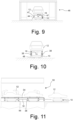
- the Figure 9 shows a schematic cross section of a transport vehicle 10, which is also guided in a tunnel 44.
- the tunnel 44 is not located here in a paint booth 43, but in a dryer 46.
- the tunnel 44 protects the transport vehicle 10 from the heat prevailing in the dryer 46.
- the personal protection sensor 16 emits microwaves.
- the inner wall of the tunnel 44 is coated with a Dallenbach absorber 47, which reflects the incident microwaves with a phase shift, which results in the reflection being suppressed as a result of destructive interference.
- the Figure 10 shows a transport vehicle 10 when a vehicle body 12 is transferred to a support structure 48 on which the vehicle body 12 is placed.
- the legs of the support structure 48, between which the transport vehicle 10 must pass, also represent objects that can be made invisible to the personal protection sensor 16 in the manner according to the invention.
- the personal protection sensor 16 of the transport vehicle 16 emits radar radiation.
- the legs of the support structure 48 carry cylindrical coverings 38 designed as foam absorbers, which absorb the incident radar radiation, making the legs invisible to the personal protection sensor 16.
- the Figure 11 shows several transport vehicles 10 driving through an assembly section 50 of a production line.
- the robots 52 used for assembly are located on an elevated assembly platform 54, which is elevated with the help of supports 56 relative to a driving floor for the vehicles 10.
- the supports 56 represent objects which must be made invisible to the personal protection sensors 16 in the manner according to the invention, since they lie in the monitoring area 18 of the personal protection sensors 16 indicated by a dashed line.
- the supports carry directionally reflective coverings 38, as shown in the Figure 7 are shown.
Landscapes
- Engineering & Computer Science (AREA)
- Physics & Mathematics (AREA)
- Radar, Positioning & Navigation (AREA)
- Automation & Control Theory (AREA)
- General Physics & Mathematics (AREA)
- Remote Sensing (AREA)
- Aviation & Aerospace Engineering (AREA)
- Optics & Photonics (AREA)
- Electromagnetism (AREA)
- Mechanical Engineering (AREA)
- Transportation (AREA)
- Combustion & Propulsion (AREA)
- Chemical & Material Sciences (AREA)
- Manufacturing & Machinery (AREA)
- Geophysics And Detection Of Objects (AREA)
- Control Of Position, Course, Altitude, Or Attitude Of Moving Bodies (AREA)
- Optical Radar Systems And Details Thereof (AREA)
- Burglar Alarm Systems (AREA)
Claims (14)
- Système de transport pour le transport de pièces à usiner (12), avecune voie,plusieurs objets (36) disposés le long de la voie,un véhicule de transport sans conducteur (10) qui a un logement de pièce à usiner (14) et un capteur de protection des personnes (16) qui présente un émetteur (30) pour la génération de rayonnement de détection (34) etun récepteur (32) qui est configuré pour recevoir du rayonnement de détection qui a été généré par l'émetteur (30) et réfléchi par des personnes ou objets (36) qui se trouvent dans une région de surveillance (18) qui est détectée par le rayonnement de détection (34),un dispositif de commande (20) qui est configuré pourcommander le véhicule de transport (10) le long de la voie de sorte qu'il n'entre pas en collision avec les objets (36),et déclencher une mesure de sécurité lorsque le capteur de protection des personnes (16) a détecté une personne dans la région de surveillance (18),caractérisé en ce queles objets (36) portent un enrobage (47) ou un revêtement (38) qui absorbe ou réfléchit du rayonnement de détection incident sur lui de manière dirigée de sorte qu'il ne peut parvenir sur le récepteur (32).
- Système de transport selon la revendication 1, caractérisé en ce que le capteur de protection des personnes (16) est un scanner laser.
- Système de transport selon la revendication 1 ou 2, caractérisé en ce que le rayonnement de détection généré par le capteur de protection des personnes (16) se propage dans un plan qui est disposé au moins approximativement parallèlement à une surface de sol sur laquelle le véhicule de transport (10) se déplace, et que les objets (36) ne portent l'enrobage (47) ou le revêtement (38) que dans une section de hauteur qui est pénétrée par le plan.
- Système de transport selon une des revendications précédentes, caractérisé en ce que le revêtement (38) présente un support à enrobage réfléchissant (40).
- Système de transport selon la revendication 4, caractérisé en ce que le support est sélectionné parmi le groupe constitué d'une feuille en plastique, d'un carton, d'une plaque métallique et d'une plaque de verre.
- Système de transport selon la revendication 5, caractérisé en ce que le support (40) est orienté de sorte que le plan d'incidence du rayonnement de détection est orienté verticalement.
- Système de transport selon la revendication 6, caractérisé en ce que le support (40) a une forme conique au moins par sections.
- Procédé d'exploitation d'un système de transport pour le transport de pièces à usiner (12), avec les étapes suivantes :a) mise à disposition d'un système de transport avec un véhicule de transport sans conducteur (10) qui a un logement de pièce à usiner (14) et un capteur de protection des personnes (16) qui présente un émetteur (30) pour la génération de rayonnement de détection (34) et un récepteur (32), dans lequel le récepteur (32) est configuré pour recevoir du rayonnement de détection qui a été généré par l'émetteur (30) et réfléchi par des personnes ou objets (36) qui se trouvent dans une région de surveillance (18) qui est détectée par le rayonnement de détection (34),b) application d'un enrobage (47) ou d'un revêtement (38) sur des objets (36) qui sont disposés le long d'une voie pour le véhicule de transport (10), dans lequel l'enrobage (47) ou le revêtement (38) absorbe ou réfléchit le rayonnement de détection (34) incident sur lui de manière dirigée de sorte qu'il ne peut parvenir sur le récepteur ;c) commande du véhicule de transport (10) le long de la voie de sorte qu'il n'entre pas en collision avec les objets (36) ;d) déclenchement d'une mesure de sécurité lorsque le capteur de protection des personnes (16) a détecté une personne dans la région de surveillance (18).
- Procédé selon la revendication 8, caractérisé en ce que le capteur de protection des personnes (16) est un scanner laser.
- Procédé selon la revendication 8 ou 9, caractérisé en ce que le rayonnement de détection généré par le capteur de protection des personnes (16) se propage dans un plan qui est disposé au moins approximativement parallèlement à une surface de sol sur laquelle le véhicule de transport (10) se déplace, et que les objets (36) ne portent l'enrobage (47) ou le revêtement (38) que dans une section de hauteur qui est pénétrée par le plan.
- Procédé selon une des revendications 8 à 10, caractérisé en ce que le revêtement (38) présente un support à enrobage réfléchissant (40).
- Procédé selon la revendication 11, caractérisé en ce que le support est sélectionné parmi le groupe constitué d'une feuille en plastique, d'un carton, d'une plaque métallique et d'une plaque de verre.
- Procédé selon la revendication 12, caractérisé en ce que le support (40) est orienté de sorte que le plan d'incidence du rayonnement de détection est orienté verticalement.
- Procédé selon la revendication 13, caractérisé en ce que le support (40) a une forme conique au moins par sections.
Priority Applications (1)
| Application Number | Priority Date | Filing Date | Title |
|---|---|---|---|
| HRP20240461TT HRP20240461T1 (hr) | 2020-01-31 | 2021-01-28 | Transportni sustav, namijenjen transportiranju izradaka i postupak rada s takvim transportnim sustavom |
Applications Claiming Priority (2)
| Application Number | Priority Date | Filing Date | Title |
|---|---|---|---|
| DE102020102513.0A DE102020102513B4 (de) | 2020-01-31 | 2020-01-31 | Transportsystem zum Transportieren von Werkstücken und Verfahren zum Betreiben eines solchen Transportsystems |
| PCT/EP2021/051970 WO2021152004A1 (fr) | 2020-01-31 | 2021-01-28 | Système de transport pour le transport de pièces et procédé pour faire fonctionner un système de transport de ce type |
Publications (2)
| Publication Number | Publication Date |
|---|---|
| EP4097553A1 EP4097553A1 (fr) | 2022-12-07 |
| EP4097553B1 true EP4097553B1 (fr) | 2024-02-28 |
Family
ID=74494897
Family Applications (1)
| Application Number | Title | Priority Date | Filing Date |
|---|---|---|---|
| EP21702630.1A Active EP4097553B1 (fr) | 2020-01-31 | 2021-01-28 | Système de transport pour le transport de pièces et procédé pour faire fonctionner un système de transport de ce type |
Country Status (9)
| Country | Link |
|---|---|
| US (1) | US12271199B2 (fr) |
| EP (1) | EP4097553B1 (fr) |
| CN (1) | CN115298631A (fr) |
| DE (1) | DE102020102513B4 (fr) |
| ES (1) | ES2978774T3 (fr) |
| HR (1) | HRP20240461T1 (fr) |
| HU (1) | HUE066745T2 (fr) |
| PL (1) | PL4097553T3 (fr) |
| WO (1) | WO2021152004A1 (fr) |
Families Citing this family (2)
| Publication number | Priority date | Publication date | Assignee | Title |
|---|---|---|---|---|
| DE102022115797A1 (de) * | 2022-06-24 | 2024-01-04 | Sick Ag | Autonom fahrendes Transportsystem zum Transport von Paletten und/oder Gitterboxen und Verfahren zum Betrieb eines solchen autonom fahrenden Transportsystems |
| JP2024106644A (ja) * | 2023-01-27 | 2024-08-08 | 株式会社豊田自動織機 | 自動運転車両 |
Family Cites Families (16)
| Publication number | Priority date | Publication date | Assignee | Title |
|---|---|---|---|---|
| DE19915509C1 (de) | 1999-04-07 | 2000-06-08 | Heraeus Quarzglas | Verfahren für die Herstellung eines zylinderförmigen Bauteils aus Quarzglas und dafür geeignete Vorrichtung |
| DE19917509C1 (de) | 1999-04-17 | 2000-05-25 | Leuze Electronic Gmbh & Co | Optoelektronische Vorrichtung |
| DE10110420A1 (de) | 2001-03-05 | 2002-09-12 | Sick Ag | Vorrichtung zur Bestimmung eines Abstandsprofils |
| DE10341128A1 (de) | 2003-09-06 | 2005-03-31 | Daimlerchrysler Ag | Vorrichtung und Verfahren zur Erfassung eines momentanen Abstandes eines Kraftfahrzeugs von einem Hindernis |
| DE102005054359A1 (de) | 2005-11-15 | 2007-05-16 | Leuze Lumiflex Gmbh & Co Kg | Schutzeinrichtung |
| ATE545045T1 (de) | 2009-12-17 | 2012-02-15 | Sick Ag | Optoelektronischer sensor |
| DE102010021042A1 (de) * | 2010-05-19 | 2011-11-24 | Fraunhofer-Gesellschaft zur Förderung der angewandten Forschung e.V. | Verfahren zur rechnergestützten Spurführung von Fahrzeugen |
| WO2012094498A2 (fr) * | 2011-01-07 | 2012-07-12 | The Regents Of The University Of Michigan | Surfaces absorbant le rayonnement électromagnétique permettant de cacher des objets en trois dimensions |
| DE202012010014U1 (de) | 2012-10-19 | 2014-01-20 | Sick Ag | Laserscanner |
| EP2722687B1 (fr) | 2012-10-22 | 2015-04-29 | Sick Ag | Dispositif de sécurité pour un véhicule |
| DE202016100485U1 (de) | 2016-02-01 | 2016-02-22 | Sick Ag | Überwachungs- oder Messsystem |
| DE102016216320A1 (de) * | 2016-08-30 | 2018-03-01 | Siemens Aktiengesellschaft | Überwachung von streckengebundenen Transportsystemen |
| WO2018081613A1 (fr) * | 2016-10-28 | 2018-05-03 | Ppg Industries Ohio, Inc. | Revêtements d'augmentation des distances de détection proche infrarouge |
| EP3330740B1 (fr) | 2016-11-30 | 2021-09-08 | Leuze electronic GmbH + Co KG | Procédé de détection d'objets dans une zone de détection |
| US10615507B1 (en) * | 2017-06-28 | 2020-04-07 | Amazon Technologies, Inc. | Unmanned aerial vehicle (UAV) landing marker responsive to radar signals |
| DE102018215885A1 (de) | 2018-09-19 | 2020-03-19 | Robert Bosch Gmbh | Lebensmittelschneidevorrichtung |
-
2020
- 2020-01-31 DE DE102020102513.0A patent/DE102020102513B4/de active Active
-
2021
- 2021-01-28 HU HUE21702630A patent/HUE066745T2/hu unknown
- 2021-01-28 HR HRP20240461TT patent/HRP20240461T1/hr unknown
- 2021-01-28 CN CN202180012195.XA patent/CN115298631A/zh active Pending
- 2021-01-28 PL PL21702630.1T patent/PL4097553T3/pl unknown
- 2021-01-28 ES ES21702630T patent/ES2978774T3/es active Active
- 2021-01-28 EP EP21702630.1A patent/EP4097553B1/fr active Active
- 2021-01-28 WO PCT/EP2021/051970 patent/WO2021152004A1/fr not_active Ceased
-
2022
- 2022-07-29 US US17/876,747 patent/US12271199B2/en active Active
Also Published As
| Publication number | Publication date |
|---|---|
| WO2021152004A1 (fr) | 2021-08-05 |
| ES2978774T3 (es) | 2024-09-19 |
| HUE066745T2 (hu) | 2024-09-28 |
| HRP20240461T1 (hr) | 2024-06-21 |
| US20220382289A1 (en) | 2022-12-01 |
| EP4097553A1 (fr) | 2022-12-07 |
| DE102020102513A1 (de) | 2021-08-05 |
| CN115298631A (zh) | 2022-11-04 |
| US12271199B2 (en) | 2025-04-08 |
| PL4097553T3 (pl) | 2024-06-24 |
| DE102020102513B4 (de) | 2022-07-07 |
Similar Documents
| Publication | Publication Date | Title |
|---|---|---|
| EP2145290B1 (fr) | Véhicule à moteur | |
| EP2339376B1 (fr) | Capteur optoélectronique | |
| DE3689612T2 (de) | Annäherungsdetektor. | |
| DE10141294B4 (de) | Verfahren zur Bodenerkennung | |
| EP4097553B1 (fr) | Système de transport pour le transport de pièces et procédé pour faire fonctionner un système de transport de ce type | |
| DE69326626T2 (de) | Verfahren und Vorrichtung zum Auffinden und Schützen von Personen und Objekten | |
| EP2987910B1 (fr) | Fraiseuse automotrice, et procédé d'évacuation de produit de fraisage | |
| DE19512681A1 (de) | Sicherheitseinrichtung für Fahrzeuge, insbesondere frei navigierende Fahrzeuge, zur Kollisionsverhinderung | |
| WO2003064802A1 (fr) | Dispositif d'actionnement automatique d'une porte, notamment d'une porte relevable | |
| DE102010046327A1 (de) | Überwachung eines mobilen Manipulators | |
| EP1304583A2 (fr) | Procédé de reconnaissance et/ou de suivi d'objets | |
| EP3301028B1 (fr) | Module de couplage comme interface entre une passerelle aéroportuaire ou un escalier pour passager et le fuselage d'un aéronef | |
| EP1788467A2 (fr) | Dispositif de protection | |
| EP3012663A1 (fr) | Systeme de securite destine a securiser l'environnement d'un objet | |
| EP3220160B9 (fr) | Aeronef equipe d'un lecteur laser | |
| EP3990997B1 (fr) | Chariot de transport autonome et système d'acheminement pour l'acheminement ainsi qu'installation de traitement pour le traitement de pièces à usiner | |
| DE10146465B4 (de) | Transportfahrzeug | |
| DE102012016708A1 (de) | Verfahren und Vorrichtung zum Überwachen eines kurveninneren Manövrierraumes eines Lastzuges | |
| WO2019211146A1 (fr) | Procédé destiné à faire fonctionner un dispositif de balayage laser et dispositif de balayage laser | |
| DE202019103533U1 (de) | Türöffnungsdetektion in Fahrzeugbehandlungsanlagen | |
| WO2019162355A1 (fr) | Engin de traitement du sol, en particulier engin de nettoyage du sol | |
| EP0351807A1 (fr) | Méthode de prévention de collisions pour véhicules automatiques, en particulier dans des systèmes de transport sans conducteurs | |
| EP4327121A1 (fr) | Dispositif de déviation de signal pour dévier des faisceaux de signaux électromagnétiques d'un appareil de détection, appareil de détection, véhicule comprenant au moins un appareil de détection et procédé pour faire fonctionner un dispositif de déviation de signal | |
| DE20221683U1 (de) | Optoelektronische Erfassungseinrichtung | |
| WO2021223920A1 (fr) | Véhicule à moteur comprenant un capteur d'environnement optique et procédé de fonctionnement d'un véhicule à moteur |
Legal Events
| Date | Code | Title | Description |
|---|---|---|---|
| STAA | Information on the status of an ep patent application or granted ep patent |
Free format text: STATUS: UNKNOWN |
|
| STAA | Information on the status of an ep patent application or granted ep patent |
Free format text: STATUS: THE INTERNATIONAL PUBLICATION HAS BEEN MADE |
|
| PUAI | Public reference made under article 153(3) epc to a published international application that has entered the european phase |
Free format text: ORIGINAL CODE: 0009012 |
|
| STAA | Information on the status of an ep patent application or granted ep patent |
Free format text: STATUS: REQUEST FOR EXAMINATION WAS MADE |
|
| 17P | Request for examination filed |
Effective date: 20220310 |
|
| AK | Designated contracting states |
Kind code of ref document: A1 Designated state(s): AL AT BE BG CH CY CZ DE DK EE ES FI FR GB GR HR HU IE IS IT LI LT LU LV MC MK MT NL NO PL PT RO RS SE SI SK SM TR |
|
| DAV | Request for validation of the european patent (deleted) | ||
| DAX | Request for extension of the european patent (deleted) | ||
| GRAP | Despatch of communication of intention to grant a patent |
Free format text: ORIGINAL CODE: EPIDOSNIGR1 |
|
| STAA | Information on the status of an ep patent application or granted ep patent |
Free format text: STATUS: GRANT OF PATENT IS INTENDED |
|
| INTG | Intention to grant announced |
Effective date: 20231026 |
|
| GRAS | Grant fee paid |
Free format text: ORIGINAL CODE: EPIDOSNIGR3 |
|
| GRAA | (expected) grant |
Free format text: ORIGINAL CODE: 0009210 |
|
| STAA | Information on the status of an ep patent application or granted ep patent |
Free format text: STATUS: THE PATENT HAS BEEN GRANTED |
|
| P01 | Opt-out of the competence of the unified patent court (upc) registered |
Effective date: 20240117 |
|
| AK | Designated contracting states |
Kind code of ref document: B1 Designated state(s): AL AT BE BG CH CY CZ DE DK EE ES FI FR GB GR HR HU IE IS IT LI LT LU LV MC MK MT NL NO PL PT RO RS SE SI SK SM TR |
|
| REG | Reference to a national code |
Ref country code: GB Ref legal event code: FG4D Free format text: NOT ENGLISH |
|
| REG | Reference to a national code |
Ref country code: CH Ref legal event code: EP |
|
| REG | Reference to a national code |
Ref country code: DE Ref legal event code: R096 Ref document number: 502021002825 Country of ref document: DE |
|
| REG | Reference to a national code |
Ref country code: IE Ref legal event code: FG4D Free format text: LANGUAGE OF EP DOCUMENT: GERMAN |
|
| REG | Reference to a national code |
Ref country code: HR Ref legal event code: T1PR Ref document number: P20240461 Country of ref document: HR |
|
| REG | Reference to a national code |
Ref country code: LT Ref legal event code: MG9D |
|
| PG25 | Lapsed in a contracting state [announced via postgrant information from national office to epo] |
Ref country code: IS Free format text: LAPSE BECAUSE OF FAILURE TO SUBMIT A TRANSLATION OF THE DESCRIPTION OR TO PAY THE FEE WITHIN THE PRESCRIBED TIME-LIMIT Effective date: 20240628 |
|
| REG | Reference to a national code |
Ref country code: NL Ref legal event code: MP Effective date: 20240228 |
|
| PG25 | Lapsed in a contracting state [announced via postgrant information from national office to epo] |
Ref country code: LT Free format text: LAPSE BECAUSE OF FAILURE TO SUBMIT A TRANSLATION OF THE DESCRIPTION OR TO PAY THE FEE WITHIN THE PRESCRIBED TIME-LIMIT Effective date: 20240228 |
|
| PG25 | Lapsed in a contracting state [announced via postgrant information from national office to epo] |
Ref country code: GR Free format text: LAPSE BECAUSE OF FAILURE TO SUBMIT A TRANSLATION OF THE DESCRIPTION OR TO PAY THE FEE WITHIN THE PRESCRIBED TIME-LIMIT Effective date: 20240529 |
|
| PG25 | Lapsed in a contracting state [announced via postgrant information from national office to epo] |
Ref country code: RS Free format text: LAPSE BECAUSE OF FAILURE TO SUBMIT A TRANSLATION OF THE DESCRIPTION OR TO PAY THE FEE WITHIN THE PRESCRIBED TIME-LIMIT Effective date: 20240528 Ref country code: NL Free format text: LAPSE BECAUSE OF FAILURE TO SUBMIT A TRANSLATION OF THE DESCRIPTION OR TO PAY THE FEE WITHIN THE PRESCRIBED TIME-LIMIT Effective date: 20240228 |
|
| PG25 | Lapsed in a contracting state [announced via postgrant information from national office to epo] |
Ref country code: RS Free format text: LAPSE BECAUSE OF FAILURE TO SUBMIT A TRANSLATION OF THE DESCRIPTION OR TO PAY THE FEE WITHIN THE PRESCRIBED TIME-LIMIT Effective date: 20240528 Ref country code: NO Free format text: LAPSE BECAUSE OF FAILURE TO SUBMIT A TRANSLATION OF THE DESCRIPTION OR TO PAY THE FEE WITHIN THE PRESCRIBED TIME-LIMIT Effective date: 20240528 Ref country code: NL Free format text: LAPSE BECAUSE OF FAILURE TO SUBMIT A TRANSLATION OF THE DESCRIPTION OR TO PAY THE FEE WITHIN THE PRESCRIBED TIME-LIMIT Effective date: 20240228 Ref country code: LT Free format text: LAPSE BECAUSE OF FAILURE TO SUBMIT A TRANSLATION OF THE DESCRIPTION OR TO PAY THE FEE WITHIN THE PRESCRIBED TIME-LIMIT Effective date: 20240228 Ref country code: IS Free format text: LAPSE BECAUSE OF FAILURE TO SUBMIT A TRANSLATION OF THE DESCRIPTION OR TO PAY THE FEE WITHIN THE PRESCRIBED TIME-LIMIT Effective date: 20240628 Ref country code: GR Free format text: LAPSE BECAUSE OF FAILURE TO SUBMIT A TRANSLATION OF THE DESCRIPTION OR TO PAY THE FEE WITHIN THE PRESCRIBED TIME-LIMIT Effective date: 20240529 Ref country code: FI Free format text: LAPSE BECAUSE OF FAILURE TO SUBMIT A TRANSLATION OF THE DESCRIPTION OR TO PAY THE FEE WITHIN THE PRESCRIBED TIME-LIMIT Effective date: 20240228 Ref country code: BG Free format text: LAPSE BECAUSE OF FAILURE TO SUBMIT A TRANSLATION OF THE DESCRIPTION OR TO PAY THE FEE WITHIN THE PRESCRIBED TIME-LIMIT Effective date: 20240228 |
|
| PG25 | Lapsed in a contracting state [announced via postgrant information from national office to epo] |
Ref country code: PT Free format text: LAPSE BECAUSE OF FAILURE TO SUBMIT A TRANSLATION OF THE DESCRIPTION OR TO PAY THE FEE WITHIN THE PRESCRIBED TIME-LIMIT Effective date: 20240628 |
|
| PG25 | Lapsed in a contracting state [announced via postgrant information from national office to epo] |
Ref country code: SE Free format text: LAPSE BECAUSE OF FAILURE TO SUBMIT A TRANSLATION OF THE DESCRIPTION OR TO PAY THE FEE WITHIN THE PRESCRIBED TIME-LIMIT Effective date: 20240228 Ref country code: PT Free format text: LAPSE BECAUSE OF FAILURE TO SUBMIT A TRANSLATION OF THE DESCRIPTION OR TO PAY THE FEE WITHIN THE PRESCRIBED TIME-LIMIT Effective date: 20240628 Ref country code: LV Free format text: LAPSE BECAUSE OF FAILURE TO SUBMIT A TRANSLATION OF THE DESCRIPTION OR TO PAY THE FEE WITHIN THE PRESCRIBED TIME-LIMIT Effective date: 20240228 |
|
| REG | Reference to a national code |
Ref country code: HU Ref legal event code: AG4A Ref document number: E066745 Country of ref document: HU |
|
| PG25 | Lapsed in a contracting state [announced via postgrant information from national office to epo] |
Ref country code: DK Free format text: LAPSE BECAUSE OF FAILURE TO SUBMIT A TRANSLATION OF THE DESCRIPTION OR TO PAY THE FEE WITHIN THE PRESCRIBED TIME-LIMIT Effective date: 20240228 |
|
| PG25 | Lapsed in a contracting state [announced via postgrant information from national office to epo] |
Ref country code: SM Free format text: LAPSE BECAUSE OF FAILURE TO SUBMIT A TRANSLATION OF THE DESCRIPTION OR TO PAY THE FEE WITHIN THE PRESCRIBED TIME-LIMIT Effective date: 20240228 |
|
| PG25 | Lapsed in a contracting state [announced via postgrant information from national office to epo] |
Ref country code: EE Free format text: LAPSE BECAUSE OF FAILURE TO SUBMIT A TRANSLATION OF THE DESCRIPTION OR TO PAY THE FEE WITHIN THE PRESCRIBED TIME-LIMIT Effective date: 20240228 |
|
| PG25 | Lapsed in a contracting state [announced via postgrant information from national office to epo] |
Ref country code: SK Free format text: LAPSE BECAUSE OF FAILURE TO SUBMIT A TRANSLATION OF THE DESCRIPTION OR TO PAY THE FEE WITHIN THE PRESCRIBED TIME-LIMIT Effective date: 20240228 |
|
| PG25 | Lapsed in a contracting state [announced via postgrant information from national office to epo] |
Ref country code: SM Free format text: LAPSE BECAUSE OF FAILURE TO SUBMIT A TRANSLATION OF THE DESCRIPTION OR TO PAY THE FEE WITHIN THE PRESCRIBED TIME-LIMIT Effective date: 20240228 Ref country code: SK Free format text: LAPSE BECAUSE OF FAILURE TO SUBMIT A TRANSLATION OF THE DESCRIPTION OR TO PAY THE FEE WITHIN THE PRESCRIBED TIME-LIMIT Effective date: 20240228 Ref country code: RO Free format text: LAPSE BECAUSE OF FAILURE TO SUBMIT A TRANSLATION OF THE DESCRIPTION OR TO PAY THE FEE WITHIN THE PRESCRIBED TIME-LIMIT Effective date: 20240228 Ref country code: EE Free format text: LAPSE BECAUSE OF FAILURE TO SUBMIT A TRANSLATION OF THE DESCRIPTION OR TO PAY THE FEE WITHIN THE PRESCRIBED TIME-LIMIT Effective date: 20240228 Ref country code: DK Free format text: LAPSE BECAUSE OF FAILURE TO SUBMIT A TRANSLATION OF THE DESCRIPTION OR TO PAY THE FEE WITHIN THE PRESCRIBED TIME-LIMIT Effective date: 20240228 |
|
| REG | Reference to a national code |
Ref country code: DE Ref legal event code: R097 Ref document number: 502021002825 Country of ref document: DE |
|
| PLBE | No opposition filed within time limit |
Free format text: ORIGINAL CODE: 0009261 |
|
| STAA | Information on the status of an ep patent application or granted ep patent |
Free format text: STATUS: NO OPPOSITION FILED WITHIN TIME LIMIT |
|
| 26N | No opposition filed |
Effective date: 20241129 |
|
| REG | Reference to a national code |
Ref country code: HR Ref legal event code: ODRP Ref document number: P20240461 Country of ref document: HR Payment date: 20250122 Year of fee payment: 5 |
|
| PG25 | Lapsed in a contracting state [announced via postgrant information from national office to epo] |
Ref country code: SI Free format text: LAPSE BECAUSE OF FAILURE TO SUBMIT A TRANSLATION OF THE DESCRIPTION OR TO PAY THE FEE WITHIN THE PRESCRIBED TIME-LIMIT Effective date: 20240228 |
|
| REG | Reference to a national code |
Ref country code: CH Ref legal event code: PL |
|
| PG25 | Lapsed in a contracting state [announced via postgrant information from national office to epo] |
Ref country code: LU Free format text: LAPSE BECAUSE OF NON-PAYMENT OF DUE FEES Effective date: 20250128 Ref country code: MC Free format text: LAPSE BECAUSE OF FAILURE TO SUBMIT A TRANSLATION OF THE DESCRIPTION OR TO PAY THE FEE WITHIN THE PRESCRIBED TIME-LIMIT Effective date: 20240228 |
|
| PG25 | Lapsed in a contracting state [announced via postgrant information from national office to epo] |
Ref country code: BE Free format text: LAPSE BECAUSE OF NON-PAYMENT OF DUE FEES Effective date: 20250131 |
|
| PG25 | Lapsed in a contracting state [announced via postgrant information from national office to epo] |
Ref country code: CH Free format text: LAPSE BECAUSE OF NON-PAYMENT OF DUE FEES Effective date: 20250131 |
|
| REG | Reference to a national code |
Ref country code: BE Ref legal event code: MM Effective date: 20250131 |
|
| PG25 | Lapsed in a contracting state [announced via postgrant information from national office to epo] |
Ref country code: IE Free format text: LAPSE BECAUSE OF NON-PAYMENT OF DUE FEES Effective date: 20250128 |
|
| PGFP | Annual fee paid to national office [announced via postgrant information from national office to epo] |
Ref country code: PL Payment date: 20251229 Year of fee payment: 6 |
|
| REG | Reference to a national code |
Ref country code: HR Ref legal event code: ODRP Ref document number: P20240461 Country of ref document: HR Payment date: 20260120 Year of fee payment: 6 |
|
| PGFP | Annual fee paid to national office [announced via postgrant information from national office to epo] |
Ref country code: HU Payment date: 20260126 Year of fee payment: 6 |
|
| PGFP | Annual fee paid to national office [announced via postgrant information from national office to epo] |
Ref country code: GB Payment date: 20260122 Year of fee payment: 6 |
|
| PGFP | Annual fee paid to national office [announced via postgrant information from national office to epo] |
Ref country code: ES Payment date: 20260217 Year of fee payment: 6 |
|
| PGFP | Annual fee paid to national office [announced via postgrant information from national office to epo] |
Ref country code: DE Payment date: 20260121 Year of fee payment: 6 |
|
| PGFP | Annual fee paid to national office [announced via postgrant information from national office to epo] |
Ref country code: HR Payment date: 20260120 Year of fee payment: 6 Ref country code: AT Payment date: 20260119 Year of fee payment: 6 |
|
| PGFP | Annual fee paid to national office [announced via postgrant information from national office to epo] |
Ref country code: IT Payment date: 20260130 Year of fee payment: 6 |
|
| PGFP | Annual fee paid to national office [announced via postgrant information from national office to epo] |
Ref country code: FR Payment date: 20260121 Year of fee payment: 6 |
|
| PGFP | Annual fee paid to national office [announced via postgrant information from national office to epo] |
Ref country code: CZ Payment date: 20260115 Year of fee payment: 6 |