EP4098170A1 - Zubehör für schlittenstaubsauger, der mit einer beweglichen gelenkabdeckung ausgestattet ist - Google Patents
Zubehör für schlittenstaubsauger, der mit einer beweglichen gelenkabdeckung ausgestattet ist Download PDFInfo
- Publication number
- EP4098170A1 EP4098170A1 EP22177079.5A EP22177079A EP4098170A1 EP 4098170 A1 EP4098170 A1 EP 4098170A1 EP 22177079 A EP22177079 A EP 22177079A EP 4098170 A1 EP4098170 A1 EP 4098170A1
- Authority
- EP
- European Patent Office
- Prior art keywords
- handle
- cover
- accessory
- suction tube
- vacuum cleaner
- Prior art date
- Legal status (The legal status is an assumption and is not a legal conclusion. Google has not performed a legal analysis and makes no representation as to the accuracy of the status listed.)
- Granted
Links
Images



Classifications
-
- A—HUMAN NECESSITIES
- A47—FURNITURE; DOMESTIC ARTICLES OR APPLIANCES; COFFEE MILLS; SPICE MILLS; SUCTION CLEANERS IN GENERAL
- A47L—DOMESTIC WASHING OR CLEANING; SUCTION CLEANERS IN GENERAL
- A47L5/00—Structural features of suction cleaners
- A47L5/12—Structural features of suction cleaners with power-driven air-pumps or air-compressors, e.g. driven by motor vehicle engine vacuum
- A47L5/22—Structural features of suction cleaners with power-driven air-pumps or air-compressors, e.g. driven by motor vehicle engine vacuum with rotary fans
- A47L5/36—Suction cleaners with hose between nozzle and casing; Suction cleaners for fixing on staircases; Suction cleaners for carrying on the back
- A47L5/362—Suction cleaners with hose between nozzle and casing; Suction cleaners for fixing on staircases; Suction cleaners for carrying on the back of the horizontal type, e.g. canister or sledge type
-
- A—HUMAN NECESSITIES
- A47—FURNITURE; DOMESTIC ARTICLES OR APPLIANCES; COFFEE MILLS; SPICE MILLS; SUCTION CLEANERS IN GENERAL
- A47L—DOMESTIC WASHING OR CLEANING; SUCTION CLEANERS IN GENERAL
- A47L5/00—Structural features of suction cleaners
- A47L5/12—Structural features of suction cleaners with power-driven air-pumps or air-compressors, e.g. driven by motor vehicle engine vacuum
- A47L5/22—Structural features of suction cleaners with power-driven air-pumps or air-compressors, e.g. driven by motor vehicle engine vacuum with rotary fans
- A47L5/36—Suction cleaners with hose between nozzle and casing; Suction cleaners for fixing on staircases; Suction cleaners for carrying on the back
- A47L5/365—Suction cleaners with hose between nozzle and casing; Suction cleaners for fixing on staircases; Suction cleaners for carrying on the back of the vertical type, e.g. tank or bucket type
-
- A—HUMAN NECESSITIES
- A47—FURNITURE; DOMESTIC ARTICLES OR APPLIANCES; COFFEE MILLS; SPICE MILLS; SUCTION CLEANERS IN GENERAL
- A47L—DOMESTIC WASHING OR CLEANING; SUCTION CLEANERS IN GENERAL
- A47L9/00—Details or accessories of suction cleaners, e.g. mechanical means for controlling the suction or for effecting pulsating action; Storing devices specially adapted to suction cleaners or parts thereof; Carrying-vehicles specially adapted for suction cleaners
- A47L9/24—Hoses or pipes; Hose or pipe couplings
- A47L9/248—Parts, details or accessories of hoses or pipes
-
- A—HUMAN NECESSITIES
- A47—FURNITURE; DOMESTIC ARTICLES OR APPLIANCES; COFFEE MILLS; SPICE MILLS; SUCTION CLEANERS IN GENERAL
- A47L—DOMESTIC WASHING OR CLEANING; SUCTION CLEANERS IN GENERAL
- A47L9/00—Details or accessories of suction cleaners, e.g. mechanical means for controlling the suction or for effecting pulsating action; Storing devices specially adapted to suction cleaners or parts thereof; Carrying-vehicles specially adapted for suction cleaners
- A47L9/32—Handles
- A47L9/327—Handles for suction cleaners with hose between nozzle and casing
Definitions
- the present invention relates more particularly to domestic vacuum cleaners of the canister type making it possible to suck up dust and waste present on a surface to be cleaned, which may for example be tiling, parquet, laminate, carpet or a rug.
- sled-type vacuum cleaner reference is made to a vacuum cleaner that can move by rolling on the ground, for example using wheels or rollers when the vacuum cleaner is in use.
- a suction nozzle is generally connected to a vacuum cleaner housing via an attachment comprising a suction tube which is rigid and a suction pipe which is flexible.
- the user of a sled vacuum cleaner holds the suction nozzle via a handle fixed to the suction tube.
- a vacuum cleaner housing of a sled vacuum cleaner is generally pulled by the user via the grip handle and the suction pipe, this mode of movement is at the origin of the name "sled vacuum cleaner".
- the name sled vacuum cleaner also covers vacuum cleaners with motorized wheels or rollers capable of following the movements of the suction nozzle, the handle or the user.
- the gripping handle more particularly has the shape of a fork comprising two parallel arms which are spaced apart from each other and which extend from two sides of the pivot connection.
- the articulation zone defined by the pivot connection comprises an articulation space in which the second end portion of the suction tube can be moved during movements of the grip handle between the first and second handle positions.
- Such an articulation space is conducive to the jamming of objects between the two parallel arms which can limit the amplitude of the rotation between the first and second stick positions or even block this rotation. Furthermore, such an articulation space is likely to induce jamming of fingers or of a hand between the two parallel arms or even to promote pinching of the fingers of a user during movements of the grip handle between the first and second sleeve positions. In addition, such an articulation space has a negative impact on the aesthetic appearance of the accessory when the grip handle occupies the first handle position.
- the present invention aims to remedy these drawbacks.
- the technical problem underlying the invention consists in particular of providing an accessory for a sled-type vacuum cleaner which is more reliable and which limits the risk of injury to the user.
- the accessory further comprises a cover mounted movably, for example on the suction tube, between a covering position in which the cover at least partially covers the articulation zone and a release position in which the cover releases at least partially the articulation zone and allows pivoting of the grip handle into the second handle position, the accessory being configured such that the cover occupies the covering position when the grip handle occupies the first handle position and such that a movement of the grip handle from the first handle position to the second handle position causes the cover to move from the cover position to the release position.
- the articulation zone of the accessory according to the present invention is at least partially covered by a cover, the interactions between the articulation zone and an external body are limited.
- the risks to see an object interact with the joint in such a way as to block or interfere with the joint, in particular by limiting its amplitude of rotation are significantly reduced.
- the risks of jamming or pinching of a user's fingers, in particular when pivoting the grip handle relative to the vacuum cleaner tube are substantially reduced.
- the presence of the aforementioned cover confers increased reliability and safety of use on the accessory according to the present invention.
- the presence of the aforementioned cover gives the accessory according to the present invention an improved aesthetic appearance when the grip handle occupies the first handle position.
- the accessory may also have one or more of the following characteristics, taken alone or in combination.
- the cover position of the cover corresponds to a raised position of the cover
- the release position corresponds to a lowered position of the cover.
- the release position of the cover corresponds to a lowered position of the cover inside the suction tube. More specifically, in this release position, the cover is lowered into a housing formed inside the second end portion of the suction tube.
- the second handle position corresponds to a storage position of the gripping handle in which the main part of the handle is folded, for example at approximately 175°, along the suction tube or against the suction tube.
- the specific configuration of the cover allows the gripping handle to be located as close as possible to the suction tube when the gripping handle occupies the storage position, and therefore to improve the compactness of the accessory when the gripping handle occupies the storage position.
- the first handle position corresponds to an unfolded position of the grip handle in which the main handle portion extends substantially parallel to the suction tube.
- the grip handle is configured to occupy a plurality of intermediate positions located between the first handle position and the second handle position and in each of which the main handle part is inclined with respect to a longitudinal axis of the suction tube.
- the cover has an outer surface of the cover which is configured to be flush with at least one outer surface adjacent to the main part of the handle when the cover occupies the covering position and the handle of grip occupies the first sleeve position.
- the outer surface of the cover is configured to be flush with at least one adjacent outer surface of the suction tube when the cover occupies the covering position and the grip handle occupies the first position sleeve.
- the outer surface of the cover has two lateral surface portions which are configured to be flush respectively with two adjacent outer surfaces of the suction tube when the cover occupies the covering position.
- the outer surface of the cover is configured to be recessed from at least one adjacent outer surface of the suction tube when the cover occupies the release position and the grip handle occupies the second sleeve position.
- the two side surface portions of the outer surface of the cover are configured to be recessed respectively with respect to two adjacent outer surfaces of the suction tube when the cover occupies the release position.
- the cover is configured to be moved into the release position by an actuation surface provided on the main handle part.
- the cover and the grip handle are configured such that a displacement of the grip handle from the first handle position to the second handle position includes a first displacement phase during which the cover is held in the cover position and a second displacement phase during which the cover is moved, for example by the handle, from the cover position to the release position.
- the cover and the grip handle are configured such that movement of the cover from the cover position to the release position begins when the grip handle reaches an intermediate position in which the main handle part is inclined with respect to the longitudinal axis of the suction tube by an angle comprised between 100° and 150°, and for example by approximately 135°.
- the accessory comprises a biasing member configured to bias the cover into the covering position.
- the cover is pivotally mounted on the suction tube around a pivot axis.
- the pivot axis is substantially parallel to the hinge axis.
- the pivot connection is located near one end of the main sleeve part.
- the articulation zone comprises an articulation space in which an end portion of the main sleeve part can be moved, the cover at least partially covering the articulation space when the cover occupies the covering position.
- the grip handle is configured to at least partially cover the cover when the grip handle occupies the second handle position.
- the main handle part is mounted articulated on the second end portion of the suction tube via the pivot connection.
- the second end portion of the suction tube comprises two lateral mounting arms, the main handle part being mounted articulated on the two lateral mounting arms via the connection pivot.
- the axis of articulation is substantially perpendicular to a longitudinal axis of the suction tube.
- the accessory comprises a locking mechanism configured to lock the grip handle in the first handle position, the locking mechanism comprising a lock movably mounted on the grip handle between a position of lock in which the lock is configured to cooperate with a locking element provided on the suction tube so as to lock the grip handle in the first handle position, and a release position in which the lock is configured to release the locking element so as to allow the handle to pivot between the first and second handle positions.
- the locking mechanism further comprises an unlocking member which is configured to be actuated by a user, for example by a finger of a user, and which is movably mounted on the handle of gripping between a first position and a second position, the locking mechanism being configured such that a movement of the unlocking member from the first position to the second position causes a movement of the lock from the locking position to the position release and such that movement of the unlocking member from the second position to the first position causes movement of the lock from the release position to the locking position.
- an unlocking member which is configured to be actuated by a user, for example by a finger of a user, and which is movably mounted on the handle of gripping between a first position and a second position, the locking mechanism being configured such that a movement of the unlocking member from the first position to the second position causes a movement of the lock from the locking position to the position release and such that movement of the unlocking member from the second position to the first position causes movement of the lock from the release position to the locking position.
- the first position of the unlocking member corresponds to a rest position of the unlocking member
- the second position of the unlocking member corresponds to an unlocking position
- the locking mechanism comprises a biasing element, such as a compression spring, configured to bias the unlocking member into the first position.
- a biasing element such as a compression spring
- the grip handle comprises a grip handle which is attached to the main handle part and which is configured to be gripped by a user.
- the accessory further comprises a suction pipe which is flexible and which is fluidly connected to the second end portion of the suction tube, the suction pipe being intended to be connected to a suction nozzle provided on a vacuum cleaner housing.
- the suction pipe is removably connected to the second end portion of the suction tube.
- the suction tube is rigid, and can for example be telescopic.
- the grip handle is telescopic.
- the vacuum cleaner further comprises a floor cleaning element, such as a suction nozzle, which is fixed, for example in a removable manner, to the first end portion of the suction tube.
- a floor cleaning element such as a suction nozzle
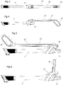
- the figures 1 to 15 represent a sled-type vacuum cleaner 1 according to the present invention.
- the vacuum cleaner 1 comprises in particular a vacuum cleaner housing 2, and a suction nozzle 3 arranged on the vacuum cleaner housing 2 and through which air carrying waste can be sucked into the vacuum cleaner housing 2.
- the vacuum cleaner 1 further comprises a vacuum motor 4 which is disposed in the vacuum cleaner housing 2.
- the vacuum motor 4 comprises an electric motor and a fan which is coupled to the electric motor and which is configured to generate a airflow through the suction nozzle 3.
- the vacuum cleaner 1 also includes a floor cleaning element 5, such as a suction nozzle, also known as a suction head.
- a floor cleaning element 5 such as a suction nozzle, also known as a suction head.
- the vacuum cleaner 1 further comprises an accessory 6 comprising a suction tube 7 comprising a first end portion 7.1 to which is fixed, for example in a removable manner, the floor cleaning element 5, and a second portion end 7.2 opposite the first end portion 7.1.
- the suction tube 7 is rigid, and can for example be telescopic.
- the accessory 6 further comprises a suction pipe 8 which is flexible.
- the suction pipe 8 has a first end which is connected, for example in a removable manner, to the suction nozzle 3, and a second end which is connected, for example in a removable manner, to the second end portion 7.2 of the suction tube 7.
- the second end portion 7.2 of the suction tube 7 advantageously comprises a connection piece 9 which is tubular and to which the second end of the suction pipe 8 is intended to be connected.
- the suction pipe 8 can for example be provided with a cleaning brush 10 located close to the second end of the suction pipe 8.
- the accessory 6 also includes a grip handle 11 comprising a main handle part 12 which is elongated and a grip handle 13 which is provided at an upper end of the main handle part 12.
- the grip handle 13 is configured to be grasped by a user so as to allow the latter to manipulate the handle 11 and therefore the suction tube 7.
- the main handle part 12 is mounted articulated on the second end portion 7.2 of the suction tube 7 via a pivot connection P which defines an articulation axis A and an articulation zone 14.
- the articulation zone 14 more particularly comprises an articulation space 14.1 in which an end portion of the main sleeve part 12 can be moved.
- main handle 12, and the axis of articulation A is substantially perpendicular to a longitudinal axis of the suction tube 7.
- the second end portion 7.2 of the suction tube 7 comprises two lateral mounting arms 15, and the main handle part 12 is hingedly mounted on the two lateral mounting arms 15 via the pivot connection P.
- the lateral mounting arms 15 partly delimit the articulation zone 14.
- the pivot link P may for example comprise a hinge pin 16 comprising a central portion extending through a through passage provided on the main handle part 12, and end portions received respectively in receiving housings provided on the side mounting arms 15.
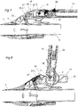
- the handle 11 is mounted to move relative to the suction tube 7 between a first handle position (see the figure 1 and 7 ), also called the unfolded position, in which the main handle part 12 extends substantially parallel to the suction tube 7, and a second handle position (see the figure 5 and 9 ), also called storage position, in which the main handle part 12 is folded, for example at about 175°, along the suction tube 7 or against the suction tube 7.
- the handle 11 is also configured to occupy a plurality of intermediate positions (see the figure 6 and 8 ) located between the first handle position and the second handle position and in each of which the main handle part 12 is inclined with respect to the longitudinal axis of the suction tube 7, for example by an angle of inclination comprised between 90 and 150°.
- a user can for example move the grip handle into one of the intermediate positions in order to be able to easily suck up waste located under a low piece of furniture or a bed.
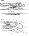
- the accessory 6 further comprises a cover 17 pivotally mounted on the suction tube 7 around a pivot axis B and between a covering position, which corresponds to a raised position of the cover 17, in which the cover 17 covers at least partially the articulation space 14.1, and a release position, which corresponds to a lowered position of the cover 17, wherein the cover 17 at least partially releases the articulation space 14.1 and allows the handle 11 to pivot into the second handle position.
- the pivot axis B is substantially parallel to the hinge axis A.
- the cover 17 is more particularly configured to occupy the covering position when the grip handle 11 occupies the first handle position, and to occupy the release position when the grip handle 11 occupies the second handle position.
- the accessory 6 is configured such that a movement of the grip handle 11 from the first handle position to the second handle position causes the cover 17 to move from the covering position to the releasing position.
- the cover 17 and the grip handle 11 are configured such that a movement of the grip handle 11 from the first handle position to the second handle position comprises a first phase of movement during which the cover 17 is held in the covering position and a second movement phase during which the cover 17 is moved by the main handle part 12, and more particularly by an actuating surface 18 provided on the main part of sleeve 12, from the covering position to the release position.
- the cover 17 and the handle 11 are configured in such a way that movement of the cover 17 from the covering position to the release position begins only when the handle 11 reaches an intermediate position (see figure 13 ) in which the main handle part 12 is inclined with respect to the longitudinal axis of the suction tube 7 by an angle of approximately 135°.
- the aforementioned second displacement phase begins when the grip handle 11, starting from the first handle position, reaches said intermediate position.
- the cover 17 comprises an outer surface of the cover 19 which is configured to be flush with at least one outer surface 20 adjacent to the main part of the handle 12 when the cover 17 occupies the covering position and the gripping handle 11 occupies the first neck position.
- the outer surface of the cover 19 comprises two lateral surface portions 19.1 which are configured to be flush respectively with two adjacent outer surfaces of the suction tube 7 when the cover 17 occupies the covering position.
- the two lateral surface portions 19.1 of the outer surface of the cover 19 are configured to be recessed respectively with respect to the two aforementioned adjacent outer surfaces of the suction tube 7 when the cover 17 occupies the release position and that the handle 11 occupies the second handle position.
- the cover 17 is lowered into a housing 30 formed inside the second end portion 7.2 of the suction tube 7.
- the accessory 6 further comprises a biasing member 21, such as a compression spring, which is interposed between the suction tube 7 and the cover 17 and which is configured to urge the cover 17 into the covering position.
- a biasing member 21 such as a compression spring
- Attachment 6 further includes a locking mechanism 22 configured to lock grip handle 11 in the first handle position.
- the locking mechanism 22 comprises a lock 23 slidably mounted on the main handle part 12 between a locking position in which the lock 23 is configured to cooperate with a locking element 24 provided on the suction tube 7 so as to lock the grip handle 11 in the first handle position, and a release position in which the lock 23 is configured to release the locking element 24 in such a way to allow the handle 11 to pivot between the first and second handle positions.
- the lock 23 more particularly comprises two lateral locking members 25, such as locking lugs, arranged respectively close to two lateral edges of the main part of the handle 12, and the locking element 24 more particularly comprises two locking housings lateral 26, such as locking recesses or locking notches, configured to cooperate respectively with the two lateral locking members 25 when the grip handle 11 occupies the first handle position and the lock 23 occupies the locking position.
- the lateral locking members 25 are mounted to slide along a direction of movement D which is substantially parallel to the longitudinal axis of the main handle part 12.
- each lateral locking housing 26 is provided on a respective lateral mounting arm 15 and more particularly on an end face of a free end of the respective lateral mounting arm 15 .
- the main handle part 12 comprises two lateral indentations 27 configured to respectively receive the two lateral mounting arms 15 when the gripping handle 11 occupies the first handle position.
- each lateral locking member 25 is configured to project into a respective lateral notch 27 when the latch 23 occupies the locking position.
- the locking mechanism 22 further comprises an unlocking member 28, such as an unlocking button, which is configured to be actuated by a user, for example by a user's finger.
- an unlocking member 28 such as an unlocking button, which is configured to be actuated by a user, for example by a user's finger.
- the unlocking member 28 is slidably mounted on the main handle part 12 between a first position, called the rest position, and a second position, called the unlocking position.
- the unlocking member 28 is mounted to slide along a sliding direction which is substantially parallel to the direction of movement D.
- the lock 23 is fixed to the unlocking member 28.
- the lock 23 and the unlocking member 28 are made in one piece, and can for example come from cast.
- the locking mechanism 22 is configured such that a movement of the unlocking member 28 from the first position to the second position causes a movement of the lock 23 from the locking position to the release position, and in such a way that a displacement of the unlocking member 28 from the second position to the first position causes a displacement of the lock 23 from the release position to the locking position.
- the locking mechanism 22 further includes a biasing element 29, such as a compression spring, configured to bias the unlocking member 28 into the first position.
- a biasing element 29 such as a compression spring
- the user When a user wishes to pivot the grip handle 11 into the storage position or into an intermediate position in which the main handle part 12 is inclined with respect to the suction tube 7, the user unlocks the grip handle 11 by displacing the unlocking member 28 into the second position against the return force exerted by the biasing element 29. Such a displacement of the unlocking member 28 causes a displacement of the lock 23 into the release position , and therefore a displacement of the two lateral locking members 25 out of the lateral locking housings 26. The user can then freely pivot the grip handle 11 relative to the suction tube 7 in such a way so that the main handle part 12 is inclined with respect to the suction tube 7 or is folded along the suction tube or against the suction tube 7.
- each lateral locking member 25 advantageously comprises an actuation ramp.
- Each actuating ramp is more particularly configured to cooperate with the respective lateral mounting arm 15, during a pivoting of the grip handle 11 towards the first handle position, so as to urge the lock 23 towards the release position, and thus allow movement of the handle 11 in the first handle position.
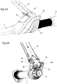
- the figure 14 and 15 represent an accessory 6 according to an embodiment of the invention which differs from that represented on the figures 1 to 13 essentially in that the accessory 6 comprises an actuating member, for example flexible or flexible, arranged in the articulation zone 14 and comprising a first end portion fixed to an inner face of the cover 17 and a second portion of end configured to be gripped by the main part of the handle 12 during movement of the gripping handle 11 from the first handle position to the second handle position, and for example at the start of the second phase of movement of the cover.
- the actuating member 31 is more particularly configured to move the cover 17 from the covering position to the releasing position when the grip handle 11 is moved from the first handle position to the second handle position.
- the actuating member 31 can for example be a actuation tab.
- the main handle part 12 could include a support member projecting from the outer surface 20 of the main handle part 12 and configured to cooperate with the edge end of the cover 17 which is located opposite the pivot axis B, the support member being configured to move the cover 17 from the covering position to the release position when the grip handle 11 is moved from the first neck position to the second neck position.
Landscapes
- Engineering & Computer Science (AREA)
- Mechanical Engineering (AREA)
- Electric Vacuum Cleaner (AREA)
Applications Claiming Priority (1)
| Application Number | Priority Date | Filing Date | Title |
|---|---|---|---|
| FR2105868A FR3123552B1 (fr) | 2021-06-03 | 2021-06-03 | Accessoire pour aspirateur traineau équipé d’un cache d’articulation mobile |
Publications (2)
| Publication Number | Publication Date |
|---|---|
| EP4098170A1 true EP4098170A1 (de) | 2022-12-07 |
| EP4098170B1 EP4098170B1 (de) | 2024-02-28 |
Family
ID=76807827
Family Applications (1)
| Application Number | Title | Priority Date | Filing Date |
|---|---|---|---|
| EP22177079.5A Active EP4098170B1 (de) | 2021-06-03 | 2022-06-02 | Zubehör für schlittenstaubsauger, der mit einer beweglichen gelenkabdeckung ausgestattet ist |
Country Status (4)
| Country | Link |
|---|---|
| EP (1) | EP4098170B1 (de) |
| CN (1) | CN221285615U (de) |
| FR (1) | FR3123552B1 (de) |
| WO (1) | WO2022254155A1 (de) |
Families Citing this family (1)
| Publication number | Priority date | Publication date | Assignee | Title |
|---|---|---|---|---|
| WO2025246785A1 (zh) * | 2024-05-27 | 2025-12-04 | 江苏美的清洁电器股份有限公司 | 清洁设备、清洁系统及控制方法 |
Citations (3)
| Publication number | Priority date | Publication date | Assignee | Title |
|---|---|---|---|---|
| KR20050047619A (ko) * | 2003-11-18 | 2005-05-23 | 주식회사 대우일렉트로닉스 | 진공청소기용 흡입 파이프 |
| JP2006311943A (ja) * | 2005-05-09 | 2006-11-16 | Silver Seiko Ltd | 電気掃除機 |
| EP2928351A1 (de) | 2012-12-10 | 2015-10-14 | Indesit Company S.p.A. | Staubsaugergriff mit einem system zur ankopplung eines schlauches |
-
2021
- 2021-06-03 FR FR2105868A patent/FR3123552B1/fr active Active
-
2022
- 2022-06-02 WO PCT/FR2022/051049 patent/WO2022254155A1/fr not_active Ceased
- 2022-06-02 EP EP22177079.5A patent/EP4098170B1/de active Active
- 2022-06-02 CN CN202290000476.3U patent/CN221285615U/zh active Active
Patent Citations (3)
| Publication number | Priority date | Publication date | Assignee | Title |
|---|---|---|---|---|
| KR20050047619A (ko) * | 2003-11-18 | 2005-05-23 | 주식회사 대우일렉트로닉스 | 진공청소기용 흡입 파이프 |
| JP2006311943A (ja) * | 2005-05-09 | 2006-11-16 | Silver Seiko Ltd | 電気掃除機 |
| EP2928351A1 (de) | 2012-12-10 | 2015-10-14 | Indesit Company S.p.A. | Staubsaugergriff mit einem system zur ankopplung eines schlauches |
Also Published As
| Publication number | Publication date |
|---|---|
| EP4098170B1 (de) | 2024-02-28 |
| FR3123552B1 (fr) | 2023-05-19 |
| FR3123552A1 (fr) | 2022-12-09 |
| WO2022254155A1 (fr) | 2022-12-08 |
| CN221285615U (zh) | 2024-07-09 |
Similar Documents
| Publication | Publication Date | Title |
|---|---|---|
| EP3900594B1 (de) | Reinigungseinheit für saugkopf | |
| EP3656268B1 (de) | Saugrohr für besenstaubsauger mit elektrischem kabel | |
| EP3834691B1 (de) | Reinigungskopf ausgestattet mit einem abnehmbaren reinigungselement | |
| EP4098170B1 (de) | Zubehör für schlittenstaubsauger, der mit einer beweglichen gelenkabdeckung ausgestattet ist | |
| EP4098163B1 (de) | Zubehör für schlittenstaubsauger | |
| EP4520240B1 (de) | Zubehör für staubsauger mit einem schlauch | |
| EP4497362B1 (de) | Staubsaugerkanal mit gelenkvorrichtung | |
| EP4176787B1 (de) | Schwenkbarer saugkopf | |
| EP4356806B1 (de) | Staubsaugerkanal mit gelenkvorrichtung | |
| EP4311465B1 (de) | Reinigungseinheit für einen saugkopf | |
| EP4356805A1 (de) | Staubsaugerkanal mit gelenkvorrichtung | |
| EP4497361B1 (de) | Staubsaugerkanal mit gelenkvorrichtung | |
| EP4186401A2 (de) | Staubsauger mit sekundärem saugkopf | |
| EP4186402A2 (de) | Staubsauger mit einem zwischen eingezogenen und ausgezogenen positionen bewegbaren saugkopf | |
| EP4563053A1 (de) | Reinigungseinheit für einen saugkopf | |
| EP4098169A1 (de) | Schlittenstaubsauger mit handgriff, der mit einer fernbedienung ausgestattet ist | |
| EP4497360A1 (de) | Flexibler kanal mit verriegelungsstift | |
| FR3160874A1 (fr) | Système de nettoyage comprenant un aspirateur et une station d’accueil apte à collecter des déchets provenant de l’aspirateur |
Legal Events
| Date | Code | Title | Description |
|---|---|---|---|
| PUAI | Public reference made under article 153(3) epc to a published international application that has entered the european phase |
Free format text: ORIGINAL CODE: 0009012 |
|
| STAA | Information on the status of an ep patent application or granted ep patent |
Free format text: STATUS: THE APPLICATION HAS BEEN PUBLISHED |
|
| AK | Designated contracting states |
Kind code of ref document: A1 Designated state(s): AL AT BE BG CH CY CZ DE DK EE ES FI FR GB GR HR HU IE IS IT LI LT LU LV MC MK MT NL NO PL PT RO RS SE SI SK SM TR |
|
| STAA | Information on the status of an ep patent application or granted ep patent |
Free format text: STATUS: REQUEST FOR EXAMINATION WAS MADE |
|
| 17P | Request for examination filed |
Effective date: 20230511 |
|
| RBV | Designated contracting states (corrected) |
Designated state(s): AL AT BE BG CH CY CZ DE DK EE ES FI FR GB GR HR HU IE IS IT LI LT LU LV MC MK MT NL NO PL PT RO RS SE SI SK SM TR |
|
| GRAP | Despatch of communication of intention to grant a patent |
Free format text: ORIGINAL CODE: EPIDOSNIGR1 |
|
| STAA | Information on the status of an ep patent application or granted ep patent |
Free format text: STATUS: GRANT OF PATENT IS INTENDED |
|
| RIC1 | Information provided on ipc code assigned before grant |
Ipc: A47L 9/32 20060101AFI20230908BHEP |
|
| INTG | Intention to grant announced |
Effective date: 20230925 |
|
| GRAS | Grant fee paid |
Free format text: ORIGINAL CODE: EPIDOSNIGR3 |
|
| GRAA | (expected) grant |
Free format text: ORIGINAL CODE: 0009210 |
|
| STAA | Information on the status of an ep patent application or granted ep patent |
Free format text: STATUS: THE PATENT HAS BEEN GRANTED |
|
| AK | Designated contracting states |
Kind code of ref document: B1 Designated state(s): AL AT BE BG CH CY CZ DE DK EE ES FI FR GB GR HR HU IE IS IT LI LT LU LV MC MK MT NL NO PL PT RO RS SE SI SK SM TR |
|
| REG | Reference to a national code |
Ref country code: GB Ref legal event code: FG4D Free format text: NOT ENGLISH |
|
| REG | Reference to a national code |
Ref country code: CH Ref legal event code: EP |
|
| REG | Reference to a national code |
Ref country code: DE Ref legal event code: R096 Ref document number: 602022002120 Country of ref document: DE |
|
| REG | Reference to a national code |
Ref country code: IE Ref legal event code: FG4D Free format text: LANGUAGE OF EP DOCUMENT: FRENCH |
|
| REG | Reference to a national code |
Ref country code: LT Ref legal event code: MG9D |
|
| PG25 | Lapsed in a contracting state [announced via postgrant information from national office to epo] |
Ref country code: IS Free format text: LAPSE BECAUSE OF FAILURE TO SUBMIT A TRANSLATION OF THE DESCRIPTION OR TO PAY THE FEE WITHIN THE PRESCRIBED TIME-LIMIT Effective date: 20240628 |
|
| REG | Reference to a national code |
Ref country code: NL Ref legal event code: MP Effective date: 20240228 |
|
| PG25 | Lapsed in a contracting state [announced via postgrant information from national office to epo] |
Ref country code: LT Free format text: LAPSE BECAUSE OF FAILURE TO SUBMIT A TRANSLATION OF THE DESCRIPTION OR TO PAY THE FEE WITHIN THE PRESCRIBED TIME-LIMIT Effective date: 20240228 |
|
| PG25 | Lapsed in a contracting state [announced via postgrant information from national office to epo] |
Ref country code: GR Free format text: LAPSE BECAUSE OF FAILURE TO SUBMIT A TRANSLATION OF THE DESCRIPTION OR TO PAY THE FEE WITHIN THE PRESCRIBED TIME-LIMIT Effective date: 20240529 |
|
| PG25 | Lapsed in a contracting state [announced via postgrant information from national office to epo] |
Ref country code: HR Free format text: LAPSE BECAUSE OF FAILURE TO SUBMIT A TRANSLATION OF THE DESCRIPTION OR TO PAY THE FEE WITHIN THE PRESCRIBED TIME-LIMIT Effective date: 20240228 Ref country code: RS Free format text: LAPSE BECAUSE OF FAILURE TO SUBMIT A TRANSLATION OF THE DESCRIPTION OR TO PAY THE FEE WITHIN THE PRESCRIBED TIME-LIMIT Effective date: 20240528 Ref country code: NL Free format text: LAPSE BECAUSE OF FAILURE TO SUBMIT A TRANSLATION OF THE DESCRIPTION OR TO PAY THE FEE WITHIN THE PRESCRIBED TIME-LIMIT Effective date: 20240228 |
|
| PG25 | Lapsed in a contracting state [announced via postgrant information from national office to epo] |
Ref country code: ES Free format text: LAPSE BECAUSE OF FAILURE TO SUBMIT A TRANSLATION OF THE DESCRIPTION OR TO PAY THE FEE WITHIN THE PRESCRIBED TIME-LIMIT Effective date: 20240228 |
|
| PG25 | Lapsed in a contracting state [announced via postgrant information from national office to epo] |
Ref country code: RS Free format text: LAPSE BECAUSE OF FAILURE TO SUBMIT A TRANSLATION OF THE DESCRIPTION OR TO PAY THE FEE WITHIN THE PRESCRIBED TIME-LIMIT Effective date: 20240528 Ref country code: NO Free format text: LAPSE BECAUSE OF FAILURE TO SUBMIT A TRANSLATION OF THE DESCRIPTION OR TO PAY THE FEE WITHIN THE PRESCRIBED TIME-LIMIT Effective date: 20240528 Ref country code: NL Free format text: LAPSE BECAUSE OF FAILURE TO SUBMIT A TRANSLATION OF THE DESCRIPTION OR TO PAY THE FEE WITHIN THE PRESCRIBED TIME-LIMIT Effective date: 20240228 Ref country code: LT Free format text: LAPSE BECAUSE OF FAILURE TO SUBMIT A TRANSLATION OF THE DESCRIPTION OR TO PAY THE FEE WITHIN THE PRESCRIBED TIME-LIMIT Effective date: 20240228 Ref country code: IS Free format text: LAPSE BECAUSE OF FAILURE TO SUBMIT A TRANSLATION OF THE DESCRIPTION OR TO PAY THE FEE WITHIN THE PRESCRIBED TIME-LIMIT Effective date: 20240628 Ref country code: HR Free format text: LAPSE BECAUSE OF FAILURE TO SUBMIT A TRANSLATION OF THE DESCRIPTION OR TO PAY THE FEE WITHIN THE PRESCRIBED TIME-LIMIT Effective date: 20240228 Ref country code: GR Free format text: LAPSE BECAUSE OF FAILURE TO SUBMIT A TRANSLATION OF THE DESCRIPTION OR TO PAY THE FEE WITHIN THE PRESCRIBED TIME-LIMIT Effective date: 20240529 Ref country code: FI Free format text: LAPSE BECAUSE OF FAILURE TO SUBMIT A TRANSLATION OF THE DESCRIPTION OR TO PAY THE FEE WITHIN THE PRESCRIBED TIME-LIMIT Effective date: 20240228 Ref country code: ES Free format text: LAPSE BECAUSE OF FAILURE TO SUBMIT A TRANSLATION OF THE DESCRIPTION OR TO PAY THE FEE WITHIN THE PRESCRIBED TIME-LIMIT Effective date: 20240228 Ref country code: BG Free format text: LAPSE BECAUSE OF FAILURE TO SUBMIT A TRANSLATION OF THE DESCRIPTION OR TO PAY THE FEE WITHIN THE PRESCRIBED TIME-LIMIT Effective date: 20240228 |
|
| PG25 | Lapsed in a contracting state [announced via postgrant information from national office to epo] |
Ref country code: PL Free format text: LAPSE BECAUSE OF FAILURE TO SUBMIT A TRANSLATION OF THE DESCRIPTION OR TO PAY THE FEE WITHIN THE PRESCRIBED TIME-LIMIT Effective date: 20240228 Ref country code: PT Free format text: LAPSE BECAUSE OF FAILURE TO SUBMIT A TRANSLATION OF THE DESCRIPTION OR TO PAY THE FEE WITHIN THE PRESCRIBED TIME-LIMIT Effective date: 20240628 |
|
| REG | Reference to a national code |
Ref country code: AT Ref legal event code: MK05 Ref document number: 1660384 Country of ref document: AT Kind code of ref document: T Effective date: 20240228 |
|
| PG25 | Lapsed in a contracting state [announced via postgrant information from national office to epo] |
Ref country code: SE Free format text: LAPSE BECAUSE OF FAILURE TO SUBMIT A TRANSLATION OF THE DESCRIPTION OR TO PAY THE FEE WITHIN THE PRESCRIBED TIME-LIMIT Effective date: 20240228 Ref country code: PT Free format text: LAPSE BECAUSE OF FAILURE TO SUBMIT A TRANSLATION OF THE DESCRIPTION OR TO PAY THE FEE WITHIN THE PRESCRIBED TIME-LIMIT Effective date: 20240628 Ref country code: PL Free format text: LAPSE BECAUSE OF FAILURE TO SUBMIT A TRANSLATION OF THE DESCRIPTION OR TO PAY THE FEE WITHIN THE PRESCRIBED TIME-LIMIT Effective date: 20240228 Ref country code: LV Free format text: LAPSE BECAUSE OF FAILURE TO SUBMIT A TRANSLATION OF THE DESCRIPTION OR TO PAY THE FEE WITHIN THE PRESCRIBED TIME-LIMIT Effective date: 20240228 |
|
| PG25 | Lapsed in a contracting state [announced via postgrant information from national office to epo] |
Ref country code: DK Free format text: LAPSE BECAUSE OF FAILURE TO SUBMIT A TRANSLATION OF THE DESCRIPTION OR TO PAY THE FEE WITHIN THE PRESCRIBED TIME-LIMIT Effective date: 20240228 |
|
| PG25 | Lapsed in a contracting state [announced via postgrant information from national office to epo] |
Ref country code: SM Free format text: LAPSE BECAUSE OF FAILURE TO SUBMIT A TRANSLATION OF THE DESCRIPTION OR TO PAY THE FEE WITHIN THE PRESCRIBED TIME-LIMIT Effective date: 20240228 |
|
| PG25 | Lapsed in a contracting state [announced via postgrant information from national office to epo] |
Ref country code: EE Free format text: LAPSE BECAUSE OF FAILURE TO SUBMIT A TRANSLATION OF THE DESCRIPTION OR TO PAY THE FEE WITHIN THE PRESCRIBED TIME-LIMIT Effective date: 20240228 Ref country code: CZ Free format text: LAPSE BECAUSE OF FAILURE TO SUBMIT A TRANSLATION OF THE DESCRIPTION OR TO PAY THE FEE WITHIN THE PRESCRIBED TIME-LIMIT Effective date: 20240228 |
|
| PG25 | Lapsed in a contracting state [announced via postgrant information from national office to epo] |
Ref country code: AT Free format text: LAPSE BECAUSE OF FAILURE TO SUBMIT A TRANSLATION OF THE DESCRIPTION OR TO PAY THE FEE WITHIN THE PRESCRIBED TIME-LIMIT Effective date: 20240228 |
|
| PG25 | Lapsed in a contracting state [announced via postgrant information from national office to epo] |
Ref country code: SK Free format text: LAPSE BECAUSE OF FAILURE TO SUBMIT A TRANSLATION OF THE DESCRIPTION OR TO PAY THE FEE WITHIN THE PRESCRIBED TIME-LIMIT Effective date: 20240228 |
|
| PG25 | Lapsed in a contracting state [announced via postgrant information from national office to epo] |
Ref country code: SM Free format text: LAPSE BECAUSE OF FAILURE TO SUBMIT A TRANSLATION OF THE DESCRIPTION OR TO PAY THE FEE WITHIN THE PRESCRIBED TIME-LIMIT Effective date: 20240228 Ref country code: SK Free format text: LAPSE BECAUSE OF FAILURE TO SUBMIT A TRANSLATION OF THE DESCRIPTION OR TO PAY THE FEE WITHIN THE PRESCRIBED TIME-LIMIT Effective date: 20240228 Ref country code: RO Free format text: LAPSE BECAUSE OF FAILURE TO SUBMIT A TRANSLATION OF THE DESCRIPTION OR TO PAY THE FEE WITHIN THE PRESCRIBED TIME-LIMIT Effective date: 20240228 Ref country code: EE Free format text: LAPSE BECAUSE OF FAILURE TO SUBMIT A TRANSLATION OF THE DESCRIPTION OR TO PAY THE FEE WITHIN THE PRESCRIBED TIME-LIMIT Effective date: 20240228 Ref country code: DK Free format text: LAPSE BECAUSE OF FAILURE TO SUBMIT A TRANSLATION OF THE DESCRIPTION OR TO PAY THE FEE WITHIN THE PRESCRIBED TIME-LIMIT Effective date: 20240228 Ref country code: CZ Free format text: LAPSE BECAUSE OF FAILURE TO SUBMIT A TRANSLATION OF THE DESCRIPTION OR TO PAY THE FEE WITHIN THE PRESCRIBED TIME-LIMIT Effective date: 20240228 Ref country code: AT Free format text: LAPSE BECAUSE OF FAILURE TO SUBMIT A TRANSLATION OF THE DESCRIPTION OR TO PAY THE FEE WITHIN THE PRESCRIBED TIME-LIMIT Effective date: 20240228 |
|
| REG | Reference to a national code |
Ref country code: DE Ref legal event code: R097 Ref document number: 602022002120 Country of ref document: DE |
|
| PG25 | Lapsed in a contracting state [announced via postgrant information from national office to epo] |
Ref country code: IT Free format text: LAPSE BECAUSE OF FAILURE TO SUBMIT A TRANSLATION OF THE DESCRIPTION OR TO PAY THE FEE WITHIN THE PRESCRIBED TIME-LIMIT Effective date: 20240228 |
|
| PG25 | Lapsed in a contracting state [announced via postgrant information from national office to epo] |
Ref country code: IT Free format text: LAPSE BECAUSE OF FAILURE TO SUBMIT A TRANSLATION OF THE DESCRIPTION OR TO PAY THE FEE WITHIN THE PRESCRIBED TIME-LIMIT Effective date: 20240228 |
|
| PLBE | No opposition filed within time limit |
Free format text: ORIGINAL CODE: 0009261 |
|
| STAA | Information on the status of an ep patent application or granted ep patent |
Free format text: STATUS: NO OPPOSITION FILED WITHIN TIME LIMIT |
|
| PG25 | Lapsed in a contracting state [announced via postgrant information from national office to epo] |
Ref country code: MC Free format text: LAPSE BECAUSE OF FAILURE TO SUBMIT A TRANSLATION OF THE DESCRIPTION OR TO PAY THE FEE WITHIN THE PRESCRIBED TIME-LIMIT Effective date: 20240228 |
|
| 26N | No opposition filed |
Effective date: 20241129 |
|
| PG25 | Lapsed in a contracting state [announced via postgrant information from national office to epo] |
Ref country code: LU Free format text: LAPSE BECAUSE OF NON-PAYMENT OF DUE FEES Effective date: 20240602 |
|
| PG25 | Lapsed in a contracting state [announced via postgrant information from national office to epo] |
Ref country code: IE Free format text: LAPSE BECAUSE OF NON-PAYMENT OF DUE FEES Effective date: 20240602 |
|
| PG25 | Lapsed in a contracting state [announced via postgrant information from national office to epo] |
Ref country code: SI Free format text: LAPSE BECAUSE OF FAILURE TO SUBMIT A TRANSLATION OF THE DESCRIPTION OR TO PAY THE FEE WITHIN THE PRESCRIBED TIME-LIMIT Effective date: 20240228 Ref country code: BE Free format text: LAPSE BECAUSE OF NON-PAYMENT OF DUE FEES Effective date: 20240630 |
|
| REG | Reference to a national code |
Ref country code: BE Ref legal event code: MM Effective date: 20240630 |
|
| PGFP | Annual fee paid to national office [announced via postgrant information from national office to epo] |
Ref country code: DE Payment date: 20250617 Year of fee payment: 4 |
|
| PGFP | Annual fee paid to national office [announced via postgrant information from national office to epo] |
Ref country code: FR Payment date: 20250630 Year of fee payment: 4 |
|
| PG25 | Lapsed in a contracting state [announced via postgrant information from national office to epo] |
Ref country code: CY Free format text: LAPSE BECAUSE OF FAILURE TO SUBMIT A TRANSLATION OF THE DESCRIPTION OR TO PAY THE FEE WITHIN THE PRESCRIBED TIME-LIMIT; INVALID AB INITIO Effective date: 20220602 |
|
| REG | Reference to a national code |
Ref country code: CH Ref legal event code: H13 Free format text: ST27 STATUS EVENT CODE: U-0-0-H10-H13 (AS PROVIDED BY THE NATIONAL OFFICE) Effective date: 20260127 |
|
| PG25 | Lapsed in a contracting state [announced via postgrant information from national office to epo] |
Ref country code: HU Free format text: LAPSE BECAUSE OF FAILURE TO SUBMIT A TRANSLATION OF THE DESCRIPTION OR TO PAY THE FEE WITHIN THE PRESCRIBED TIME-LIMIT; INVALID AB INITIO Effective date: 20220602 |
|
| PG25 | Lapsed in a contracting state [announced via postgrant information from national office to epo] |
Ref country code: CH Free format text: LAPSE BECAUSE OF NON-PAYMENT OF DUE FEES Effective date: 20250630 |