EP4098192B1 - Appareil de mesure d'informations biométriques - Google Patents
Appareil de mesure d'informations biométriques Download PDFInfo
- Publication number
- EP4098192B1 EP4098192B1 EP21789098.7A EP21789098A EP4098192B1 EP 4098192 B1 EP4098192 B1 EP 4098192B1 EP 21789098 A EP21789098 A EP 21789098A EP 4098192 B1 EP4098192 B1 EP 4098192B1
- Authority
- EP
- European Patent Office
- Prior art keywords
- sensor
- biometric information
- impedance
- load unit
- bioelectrode
- Prior art date
- Legal status (The legal status is an assumption and is not a legal conclusion. Google has not performed a legal analysis and makes no representation as to the accuracy of the status listed.)
- Active
Links
Images


Classifications
-
- A—HUMAN NECESSITIES
- A61—MEDICAL OR VETERINARY SCIENCE; HYGIENE
- A61B—DIAGNOSIS; SURGERY; IDENTIFICATION
- A61B5/00—Measuring for diagnostic purposes; Identification of persons
- A61B5/145—Measuring characteristics of blood in vivo, e.g. gas concentration or pH-value ; Measuring characteristics of body fluids or tissues, e.g. interstitial fluid or cerebral tissue
- A61B5/14503—Measuring characteristics of blood in vivo, e.g. gas concentration or pH-value ; Measuring characteristics of body fluids or tissues, e.g. interstitial fluid or cerebral tissue invasive, e.g. introduced into the body by a catheter or needle or using implanted sensors
-
- A—HUMAN NECESSITIES
- A61—MEDICAL OR VETERINARY SCIENCE; HYGIENE
- A61B—DIAGNOSIS; SURGERY; IDENTIFICATION
- A61B5/00—Measuring for diagnostic purposes; Identification of persons
- A61B5/145—Measuring characteristics of blood in vivo, e.g. gas concentration or pH-value ; Measuring characteristics of body fluids or tissues, e.g. interstitial fluid or cerebral tissue
- A61B5/14532—Measuring characteristics of blood in vivo, e.g. gas concentration or pH-value ; Measuring characteristics of body fluids or tissues, e.g. interstitial fluid or cerebral tissue for measuring glucose, e.g. by tissue impedance measurement
-
- A—HUMAN NECESSITIES
- A61—MEDICAL OR VETERINARY SCIENCE; HYGIENE
- A61B—DIAGNOSIS; SURGERY; IDENTIFICATION
- A61B5/00—Measuring for diagnostic purposes; Identification of persons
- A61B5/145—Measuring characteristics of blood in vivo, e.g. gas concentration or pH-value ; Measuring characteristics of body fluids or tissues, e.g. interstitial fluid or cerebral tissue
- A61B5/1468—Measuring characteristics of blood in vivo, e.g. gas concentration or pH-value ; Measuring characteristics of body fluids or tissues, e.g. interstitial fluid or cerebral tissue using chemical or electrochemical methods, e.g. by polarographic means
- A61B5/1473—Measuring characteristics of blood in vivo, e.g. gas concentration or pH-value ; Measuring characteristics of body fluids or tissues, e.g. interstitial fluid or cerebral tissue using chemical or electrochemical methods, e.g. by polarographic means invasive, e.g. introduced into the body by a catheter
-
- A—HUMAN NECESSITIES
- A61—MEDICAL OR VETERINARY SCIENCE; HYGIENE
- A61B—DIAGNOSIS; SURGERY; IDENTIFICATION
- A61B5/00—Measuring for diagnostic purposes; Identification of persons
- A61B5/15—Devices for taking samples of blood
- A61B5/155—Devices specially adapted for continuous or multiple sampling, e.g. at predetermined intervals
-
- A—HUMAN NECESSITIES
- A61—MEDICAL OR VETERINARY SCIENCE; HYGIENE
- A61B—DIAGNOSIS; SURGERY; IDENTIFICATION
- A61B5/00—Measuring for diagnostic purposes; Identification of persons
- A61B5/68—Arrangements of detecting, measuring or recording means, e.g. sensors, in relation to patient
- A61B5/6846—Arrangements of detecting, measuring or recording means, e.g. sensors, in relation to patient specially adapted to be brought in contact with an internal body part, i.e. invasive
- A61B5/6847—Arrangements of detecting, measuring or recording means, e.g. sensors, in relation to patient specially adapted to be brought in contact with an internal body part, i.e. invasive mounted on an invasive device
- A61B5/686—Permanently implanted devices, e.g. pacemakers, other stimulators, biochips
-
- A—HUMAN NECESSITIES
- A61—MEDICAL OR VETERINARY SCIENCE; HYGIENE
- A61B—DIAGNOSIS; SURGERY; IDENTIFICATION
- A61B5/00—Measuring for diagnostic purposes; Identification of persons
- A61B5/68—Arrangements of detecting, measuring or recording means, e.g. sensors, in relation to patient
- A61B5/6846—Arrangements of detecting, measuring or recording means, e.g. sensors, in relation to patient specially adapted to be brought in contact with an internal body part, i.e. invasive
- A61B5/6885—Monitoring or controlling sensor contact pressure
-
- A—HUMAN NECESSITIES
- A61—MEDICAL OR VETERINARY SCIENCE; HYGIENE
- A61B—DIAGNOSIS; SURGERY; IDENTIFICATION
- A61B5/00—Measuring for diagnostic purposes; Identification of persons
- A61B5/72—Signal processing specially adapted for physiological signals or for diagnostic purposes
- A61B5/7203—Signal processing specially adapted for physiological signals or for diagnostic purposes for noise prevention, reduction or removal
- A61B5/7207—Signal processing specially adapted for physiological signals or for diagnostic purposes for noise prevention, reduction or removal of noise induced by motion artifacts
-
- A—HUMAN NECESSITIES
- A61—MEDICAL OR VETERINARY SCIENCE; HYGIENE
- A61B—DIAGNOSIS; SURGERY; IDENTIFICATION
- A61B5/00—Measuring for diagnostic purposes; Identification of persons
- A61B5/72—Signal processing specially adapted for physiological signals or for diagnostic purposes
- A61B5/7203—Signal processing specially adapted for physiological signals or for diagnostic purposes for noise prevention, reduction or removal
- A61B5/7207—Signal processing specially adapted for physiological signals or for diagnostic purposes for noise prevention, reduction or removal of noise induced by motion artifacts
- A61B5/721—Signal processing specially adapted for physiological signals or for diagnostic purposes for noise prevention, reduction or removal of noise induced by motion artifacts using a separate sensor to detect motion or using motion information derived from signals other than the physiological signal to be measured
-
- A—HUMAN NECESSITIES
- A61—MEDICAL OR VETERINARY SCIENCE; HYGIENE
- A61B—DIAGNOSIS; SURGERY; IDENTIFICATION
- A61B5/00—Measuring for diagnostic purposes; Identification of persons
- A61B5/72—Signal processing specially adapted for physiological signals or for diagnostic purposes
- A61B5/7235—Details of waveform analysis
- A61B5/725—Details of waveform analysis using specific filters therefor, e.g. Kalman or adaptive filters
-
- A—HUMAN NECESSITIES
- A61—MEDICAL OR VETERINARY SCIENCE; HYGIENE
- A61B—DIAGNOSIS; SURGERY; IDENTIFICATION
- A61B2562/00—Details of sensors; Constructional details of sensor housings or probes; Accessories for sensors
- A61B2562/18—Shielding or protection of sensors from environmental influences, e.g. protection from mechanical damage
Definitions
- the present invention relates to a body-attachable-type apparatus for measuring biometric information, and more specifically relates to a body-attachable-type apparatus for measuring biometric information, the apparatus in which, by connecting an additional impedance to a sensor impedance, a level of noise generated during deformation or movement of the sensor can be reduced, thereby accurately measuring biometric information, and by removing noise affecting a response signal during deformation or movement of the sensor through the additional impedance, the biometric information can be accurately measured.
- Diabetes is a major cause of death and a cause of disability worldwide, and therefore, many people have health problems due to diabetes.
- diabetes is a serious disease that causes heart and kidney disease, blindness, nerve damage and high blood pressure.
- the incidence of complications can be significantly reduced by appropriately managing blood glucose levels. Therefore, it is important to continuously manage diabetes, an important factor is self-monitoring of blood glucose levels.
- a self-diagnosis biometer in which a user can check a blood glucose level of the user by himself or herself has been widely distributed and used.
- a conventional blood glucose meter measures the blood glucose level of the user by putting the user's blood on a sensor strip, which is a test strip. Accordingly, the sensor strip with the blood is inserted into the blood glucose meter, and the blood glucose level measured through the sensor strip is displayed on the blood glucose meter.
- the blood glucose meter receives an electrical signal generated by an electrochemical reaction between the collected blood and the reactant in the sensor strip, and measures the blood glucose level.
- a blood-collect-type blood glucose meter finger prick method helps diabetic patients to manage blood glucose, but it is difficult to accurately identify the blood glucose levels which are being frequently changed because it shows only the result at the time of the measurement.
- Diabetics patients generally experience hyperglycemia and hypoglycemia, an emergency may occur in the hypoglycemic conditions, and the patients may become unconscious or die if a hypoglycemic condition lasts for an extended period of time without the supply of sugar. Accordingly, although rapid discovery of the hypoglycemic condition is critically important for diabetics, blood-collecting type glucose monitoring devices intermittently measuring glucose have limited ability to accurately measure blood glucose levels.
- CGMSs continuous glucose monitoring systems
- the continuous blood glucose measurement system measures biometric information of blood glucose by collecting test substance such as blood of human body in a state that a part of a sensor is inserted in the human body.
- a sensor transmitter measuring biometric information in a state of being attached to the human body and a communication terminal receiving the measured biometric information data from the sensor transmitter are comprised.
- a body-attachable-type biometric information measurement apparatus such as a sensor transmitter for continuous blood glucose measurement
- blood glucose information is measured in a state in which the sensor transmitter is attached to the body and a part of the sensor is inserted into the human body
- a physical force applied to the sensor or an area around the body part where the sensor is inserted, causes the sensor to be deformed or moved, as the sensor moves in this way
- the noise may be included in the biometric information data measured by the sensor transmitter, and this affects the response signal generated by the sensor transmitter, thereby making difficult in accurately measuring the biometric information.
- Document KR 2016 0 132 750 A discloses an electrode structure for a bio sensor comprising a motion electrode, which can invade an object to be examined, and a first and a second impedance electrodes, which can be in contact with the object to be examined.
- the motion electrode includes an enzyme for converting a first electric reaction into a second electric reaction, corresponding to a first electric stimulus, which is applied to the object to be examined.
- the impedance electrodes receive the first and second electric reactions from the object to be examined, and are mutually separated and arranged.
- the purpose of the present invention is to provide an apparatus for measuring biometric information, the apparatus which can accurately measure the biometric information by reducing a level of noise generated during deformation or movement of the sensor in a body-attachable-type apparatus for measuring biometric information.
- Another purpose of the present invention is to provide an apparatus for measuring biometric information, the apparatus in which, by removing a level of noise affecting a response signal during deformation or movement of the sensor through an additionally arranged electrical load as well as further removing noise from a response signal including high frequency components of the noise, the biometric information can be accurately measured.
- Still another purpose of the present invention is to provide an apparatus for measuring biometric information, the apparatus in which, by arranging an electrical load at a position of a sensor or a measurement module or a position where the sensor and the measurement module are coupled according to various embodiment of the present invention, biometric information can be accurately measured.
- the present invention provides an apparatus for measuring biometric information in accordance with claim 1.
- the apparatus comprises: a sensor including a bioelectrode configured to be insertable into skin; a measurement module configured to apply a measurement power to the bioelectrode and measure the biometric information based on a response signal received from the bioelectrode; and a load unit configured to add an additional impedance to a sensor impedance of the sensor to relatively reduce a level of noise applied to the response signal by physical deformation of the sensor, wherein a level of the additional impedance is greater than a level of the sensor impedance.
- the bioelectrode comprises a working electrode and a reference electrode
- the load unit is connected in series with the working electrode, or is connected in series with the reference electrode, or is connected in series with the working electrode and the reference electrode, respectively.
- the load unit is arranged in series with the bioelectrode inside a housing of the measurement module.
- the load unit is formed at a body of the sensor and is formed as a tracer electrically connecting the bioelectrode and the measurement module.
- the sensor and the measurement module are coupled separably to each other, and the load unit is formed as a connection terminal electrically connecting the sensor and the measurement module to each other when the sensor and the measurement module are coupled.
- the load unit is a resistor of 10K ⁇ to 10G ⁇ .
- the measurement module comprises a temperature sensor configured to measure a temperature of the load unit, and the biometric information is measured from the response signal considering the additional impedance of the load unit that is changed according to the temperature measured by the temperature sensor.
- An apparatus for measuring biometric information according to the present invention has the following effects.
- an apparatus for measuring biometric information by connecting an additional impedance to a sensor impedance in a body-attachable-type apparatus for measuring biometric information, reduces a level of noise generated during deformation or movement of the sensor, thereby accurately measuring the biometric information.
- an apparatus for measuring biometric information can accurately measure the biometric information by removing a level of noise affecting a response signal during deformation or movement of the sensor through an additionally arranged electrical load as well as further removing noise from a response signal including high frequency components of the noise.
- an apparatus for measuring biometric information can accurately measure the biometric information according to various embodiments, by arranging an electrical load at a position of a sensor or a measurement module or a position where the sensor and the measurement module are coupled.
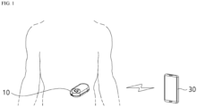
- FIG. 1 is a schematic diagram for illustrating a body attachable type continuous biometric information measurement system according to an embodiment of the present disclosure.
- the continuous biometric information measurement system comprises a biometric information measurement apparatus (10) and a communication terminal (30).
- the biometric information measurement apparatus (10) includes a sensor having a bioelectrode configured to be insertable into the body and a measuring module configured to measure biometric information based on a response signal received from the bioelectrode.
- the bioelectrode of the sensor is inserted into the skin to generate an electrochemical reaction and generates a response signal, and the measurement module measures biometric information such as blood glucose and so on based on the response signal.
- the measurement module transmits the measured biometric information to the communication terminal in real time or periodically or when the communication terminal requests it.
- the senor and the measurement module may be manufactured in an integral type, but the sensor and the measurement module may be manufactured to be separable from or couplable to each other.
- the sensor and the measurement module When the sensor and the measurement module are manufactured to be separable from or couplable to each other, the sensor and the measurement module have connection terminals that electrically contact each other, and a response signal generated by the sensor is provided to the measurement module through the connection terminals.
- the communication terminal (30) is a terminal configured to receive biometric information from the biometric information measurement apparatus (10) and output or display the received biometric information to a user, and for example, the biometric information measurement apparatus (10) may be a portable terminal (such as smartphone, tablet PC, or notebook and so on) configured to communicate with the biometric information measurement apparatus (10).
- the communication terminal (30) is not limited thereto, and may be any type of a terminal which has a communication function and program or application can be installed to.
- the biometric information measurement apparatus (10) transmits the biometric information in response to request of the communication terminal (30) or at predetermined times periodically, and for data communication between the biometric information measurement apparatus (10) and the communication terminal (30), the biometric information measurement apparatus (10) and the communication terminal (30) are communicationally connected to each other over a wire by an USB cable and so on or communicationally connected in an wireless communication means such as infrared communication, NFC communication, Bluetooth, etc.
- FIG. 2 is a diagram for illustrating an applicator for attaching a biometric information measurement apparatus to a human body according to an embodiment of the present invention.
- the biometric information measurement apparatus (10) is mounted in the applicator (50), and the applicator (50) can be operated so that the biometric information measurement apparatus (10) can be outwardly discharged to the outside of the applicator (50) by the manipulation of the user and then be attached to a specific portion of the human body of the user.
- the applicator (50) is formed to have a shape that one side of the applicator (50) is open, and the biometric information measurement apparatus (10) is installed to the applicator (50) through the open side of the applicator (50).
- the applicator (50) When the biometric information measurement apparatus (10) is attached to a part of the human body using the applicator (50), for inserting an end portion of the sensor included in the biometric information measurement apparatus (10) to skin, the applicator (50) comprises a needle (not shown) formed to cover the end portion of the sensor therein, a first elastic means (not shown) pushing the needle and the end portion of the sensor together towards the skin, and a second elastic means (not shown) configured to retract the needle only.
- the compressed state of the first elastic means (not shown) arranged to be compressed inside the applicator (50) by the configuration of the applicator (50) can be released, thereby inserting the needle and the end portion of the sensor simultaneously to the skin, and when the end portion of the sensor is inserted to the skin, the compressed state of the second elastic means (not shown) is released, thereby extracting the needle only.
- the applicator (50) the user can safely and easily attach the biometric information measurement apparatus (10) to the skin.
- An adhesive tape is provided at a surface of the biometric information measurement apparatus (10) contacting the human body so that the biometric information measurement apparatus (10) can be attached to the skin. Accordingly, if the applicator (50) is moved away from the skin of the human body, the biometric information measurement apparatus (10) is fixedly attached to the skin of the human body by the adhesive tape.
- the biometric information measurement apparatus (10) After that, if the power is supplied to the biometric information measurement apparatus (10), the biometric information measurement apparatus (10) is communicationally connected with the communication terminal (30), and the biometric information measurement apparatus (10) transmits the measured biometric information to the communication terminal (30).
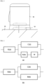
- FIG. 3 is a diagram for illustrating an Randles equivalent circuit of a sensor.
- the Randles equivalent circuit is an electric circuit for modeling an electrochemical reaction occurring between a bioelectrode and an electrolyte, that is, an interface of a bodily fluid
- R1(t) is a resistance of the body fluid
- C1(t) is a capacitance by an electric double layer
- R2(t) is a charge transfer resistance
- W is a Warburg impedance.
- a film is positioned on the movement path of ions as shown in FIG. 3(b) , in the Randles equivalent circuit, the sum of impedances such as resistance, capacitance and so on is a sensor impedance.
- an electrode where an electrochemical reaction occurs is not directly exposed to the sensor, but a diffusion membrane controlling a diffusion rate of a target material and a biocompatible protective layer suppressing a biological immune response has a structure surrounding the sensor.
- These films can be added in series at a R1(t) position corresponding to a resistance of the body fluid in the Randles circuit. It is common to interpret these films as a parallel structure of a resistor and a capacitor.
- One of the many cases in which noise is generated by an external force applied to the sensor is changing components of the equivalent circuit shown in FIG. 3 .
- biometric information measurement apparatus (10) is attached to the body and biometric information is measured in a state in which the bioelectrode of the sensor is inserted into the body, whenever the user moves, a physical force is applied to the sensor or the body part adjacent to where the sensor is inserted, thereby deforming or moving the sensor, and in this process, impedance components expressed with the equivalent circuit of the sensor are changed by an external force, noise may be included in the response signal generated by the sensor according to the change in the impedance component, and in this way, when the biometric information is measured from the response signal including the noise, the biometric information of the user cannot be accurately measured.
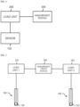
- FIG. 4 is a functional block diagram for illustrating a biometric information measurement apparatus that can reduce the size of noise generated by movement of a sensor according to an embodiment of the present invention.
- a bioelectrode is formed in the sensor (100), and the bioelectrode is inserted into the body, thereby causing an oxidation-reduction reaction and generating a response signal.
- a measurement module (300) provides a measurement power to the bioelectrode of the sensor (100) and measures biometric information based on the response signal received from the bioelectrode of the sensor (100).
- the measurement module (300) includes a communicator to communicate with the communication terminal, and the measurement module (300) transmits the measured biometric information to the communication terminal in real time, or transmits the measured biometric information to the communication terminal through the communicator when the communication terminal requests.
- the biometric information measurement apparatus includes a load unit (200) configured to relatively suppress a noise level applied to the response signal generated by the sensor (100) when the sensor (100) is physically deformed by providing an additional impedance to a sensor impedance of the sensor (100).
- the magnitude of the additional impedance of the load unit (200) is larger than the magnitude of the sensor impedance of the sensor (100).
- the load unit (200) is a resistor of 10K ⁇ to 10G ⁇ .
- the effect of the change in the sensor impedance according to the physical change of the sensor (100) becomes relatively low in the overall impedance of the biometric information measurement apparatus, and due to this, even if the physical deformation occurs in the sensor (100), the amount of noise applied to the generated response signal can be reduced.
- a working electrode and a counter electrode (150) are formed at one end portion of the sensor, and a load unit 1 (201) is connected only to the working electrode and a separate load is not connected to the counter electrode (150), or a load part 2 (203) is connected only to the counter electrode (150) and a separate load is not connected to the working electrode , or the load unit 1 (201) and the load unit 2 (203) are connected to the working electrode and the counter electrode (150), respectively.
- FIG. 6 is a diagram for explaining an example of a bioelectrode measurement apparatus according to the present invention.
- the sensor (100) includes a flexible base substrate (110), a bioelectrode (130) disposed at one end portion of the base substrate (110), and a conductive tracer (150) formed on an upper surface of the base substrate (110).
- the bioelectrode (130) disposed at one end portion of the base substrate (110) is inserted into the skin, thereby occurring electrochemical reaction inside the body, and generates a response signal by the electrochemical reaction, and the generated response signal is transmitted along the conductive tracer (150) to a measurement circuit unit (310) of the measurement unit (300).
- the measurement circuit unit (310) provides a measurement power to the bioelectrode (130) and measures biometric information of the user by receiving a response signal according to an electrochemical reaction from the bioelectrode according to the measurement power, and the measurement circuit unit (310) stores the measured biometric information in an internal memory or transmits the measured biometric information to the communication terminal.
- a load unit (200) is connected to the sensor (100) to provide additional impedance to the sensor impedance of the sensor (100), and therefore, this can contribute to reduce a level of noise generated when a shape of the sensor is deformed or the sensor moves according to a physical load applied to the sensor when a response signal is continuously generated by attaching the sensor to the body. That is, the magnitude of the total impedance in a view of the measurement circuit unit (310) is the sum of the sensor impedance of the sensor (100) and the additional impedance of the load unit
- the magnitude of the additional impedance is relatively greater than the magnitude of the sensor impedance. Therefore, even if the sensor impedance is changed due to deformation or movement in or of the sensor, the effect or contribution of the change in the sensor impedance with respect to the overall impedance is small, and accordingly, the amount of noise generated in the response signal generated by the sensor can be reduced.
- FIG. 7 is a diagram for explaining another example of a biometric information measurement apparatus according to the present invention.
- a load unit (200) may be manufactured as a conductive tracer of the sensor (100).
- a sensor (100) includes a flexible base substrate (110), a bioelectrode (130) disposed at one end portion of the base substrate (110), and a conductive tracer formed on the upper surface of the base substrate (110), and in another example of a biometric information measurement apparatus according to the present invention, a conductive trace may be manufactured as the load unit (200) instead of a separate load unit.
- the bioelectrode (130) disposed on one end portion of the base substrate 110 is inserted into the skin, this causes an electrochemical reaction inside the body, thereby generating a response signal, and the generated response signal is transmitted along the conductive tracer to the measurement circuit unit (310) of the measurement unit (300).
- a conductive tracer is formed to have an impedance as small as possible, but in another example of a biometric information measurement apparatus according to the present invention, a conductive tracer is manufactured to have a relatively high impedance in order to operate the conductive tracer as the load unit (200).
- the conductive tracer may be manufactured to have a high impedance by varying a material, shape, width, and length of the conductive tracer and so on.
- the effect or contribution of the change in the sensor impedance with respect to the overall impedance is small, and accordingly, the amount of noise generated in the response signal generated by the sensor can be reduced.
- FIG. 8 is a diagram for explaining another example of a biometric information measurement apparatus according to the present invention.
- the sensor (100) and the measurement unit (300) are manufactured independently and are manufactured to be separable from or couplable to each other, and connection terminals (210, 230) for electrically connecting the sensor (100) and the measurement unit (300) when being coupled to each other are formed at the sensor (100) and the measurement unit (300). That is, the first connection terminal (210) is formed at one end of the sensor (100) couplable with the measurement unit (300), and the second connection terminal (230) for electrically connecting the measurement unit (300) with the sensor (100) is formed at the measurement unit (300).
- a response signal generated from the bioelectrode of the sensor (100) is transmitted to the first connection terminal (210) through the conductive tracer, and the second connection terminal (230) electrically connected to the first connection terminal (210) receives the response signal and transmits it to the measurement circuit unit (310).
- connection terminals are manufactured to have a relatively high impedance in order to operate connection terminals (210, 230) as the load unit (200).
- connection terminals (210, 230) may be manufactured to have a high impedance by varying a material, shape, width, and length of the connection terminals (210, 230) and so on.
- the load unit (200) provides an additional impedance to the sensor impedance of the sensor (100) in order to contribute to reduce a level of noise generated when a shape of the sensor is deformed or the sensor moves according to a physical load applied to the sensor when a response signal is continuously generated by attaching the sensor to the body. That is, the magnitude of the total impedance in a view of the measurement circuit unit (310) is the sum of the sensor impedance of the sensor (100) and the additional impedance of the load unit (200), and the magnitude of the additional impedance is relatively greater than the magnitude of the sensor impedance.
- the effect or contribution of the change in the sensor impedance with respect to the overall impedance is small, and accordingly, the amount of noise generated in the response signal generated by the sensor can be reduced.
- FIG. 9 is a diagram for explaining another example of a biometric information measurement apparatus according to the present invention.
- the measurement unit (300) includes a power supplier (310), a current-voltage converter (330), a biometric information generation module (370), and a temperature sensor (390).
- the power supplier (310) applies a measurement power to the sensor, and the current-voltage converter (330) receives an analog current of a response signal from the sensor and converts it into a voltage of a measurement signal.
- the current-voltage converter (330) may be OPAMP.
- the biometric information generation module (370) converts the analog measurement signal to digital to generate biometric information.
- the level of an electrical load of the load unit (200) that is, the level of an additional impedance, is changed according to the temperature of the load unit (200), and the temperature sensor (390) measures a temperature of the load unit itself, and provides information on the measured temperature to the biometric information generation module (370).
- the biometric information generation module (370) determines the level of the additional impedance in consideration of the temperature of the load unit (200) based on the measured temperature, and the biometric information can be accurately measured from the response signal based on the determined level of the additional impedance.
- the measurement circuit unit described above with reference to FIGS. 5 to 8 includes a power supplier (310), a current-voltage converter (330), a biometric information generation module (370) and a temperature sensor (390), and can operate in the same manner.
- another example of a biometric information measurement apparatus further includes a filter unit (350), and the filter unit (350) filters a measurement signal converted into a voltage with a low-frequency band-pass filter to remove a high-frequency component of noise from the measurement signal.
- the filter unit (350) filters a measurement signal converted into a voltage with a low-frequency band-pass filter to remove a high-frequency component of noise from the measurement signal.
- a biometric information measurement apparatus further includes a filter unit (350), by adding an additional impedance to a sensor impedance through the load unit (200), even if the sensor impedance is changed, the contribution of the change in the sensor impedance becomes small, thereby reducing the level of the noise in a current of a response signal applied to the current-voltage converter (330), and additionally, by removing high-frequency components of the noise from the measurement signal converted through the filter unit (350), the biometric information can be measured more accurately.
- a filter unit (350) by adding an additional impedance to a sensor impedance through the load unit (200), even if the sensor impedance is changed, the contribution of the change in the sensor impedance becomes small, thereby reducing the level of the noise in a current of a response signal applied to the current-voltage converter (330), and additionally, by removing high-frequency components of the noise from the measurement signal converted through the filter unit (350), the biometric information can be measured more accurately.
- OPAMP is used as the current-voltage converter (330), the current of the response signal of which the level of the noise is reduced through the load unit (200) is amplified by the current-voltage converter (330) to generate a voltage of the measurement signal, therefore through the combination of the load unit (200) and the filter unit (350), the amplification rate of the current-voltage converter (330) can be increased to reduce the measurement range, and it is possible to accurately measure the biometric information by being less affected by noise than simply using the filter unit (350) alone.
Landscapes
- Health & Medical Sciences (AREA)
- Life Sciences & Earth Sciences (AREA)
- Engineering & Computer Science (AREA)
- Physics & Mathematics (AREA)
- Surgery (AREA)
- Public Health (AREA)
- Veterinary Medicine (AREA)
- Biophysics (AREA)
- Pathology (AREA)
- General Health & Medical Sciences (AREA)
- Biomedical Technology (AREA)
- Heart & Thoracic Surgery (AREA)
- Medical Informatics (AREA)
- Molecular Biology (AREA)
- Animal Behavior & Ethology (AREA)
- Signal Processing (AREA)
- Optics & Photonics (AREA)
- Physiology (AREA)
- Psychiatry (AREA)
- Artificial Intelligence (AREA)
- Computer Vision & Pattern Recognition (AREA)
- Emergency Medicine (AREA)
- General Chemical & Material Sciences (AREA)
- Chemical Kinetics & Catalysis (AREA)
- Chemical & Material Sciences (AREA)
- Hematology (AREA)
- Measurement And Recording Of Electrical Phenomena And Electrical Characteristics Of The Living Body (AREA)
- Measurement Of The Respiration, Hearing Ability, Form, And Blood Characteristics Of Living Organisms (AREA)
- Measuring And Recording Apparatus For Diagnosis (AREA)
- Measuring Pulse, Heart Rate, Blood Pressure Or Blood Flow (AREA)
Claims (7)
- Appareil (10) de mesure d'informations biométriques, ledit appareil (10) comprenant:un capteur (100) comprenant une bioélectrode (130) prévue pour être insérable sous la peau (20) ;un module de mesure (300) prévu pour appliquer une puissance de mesure à la bioélectrode (130) et mesurer les informations biométriques sur la base d'un signal de réponse reçu de la bioélectrode (130); etune unité de charge (200) prévue pour ajouter une impédance additionnelle à une impédance du capteur (100) afin de réduire relativement un niveau de bruit appliqué au signal de réponse par déformation physique du capteur (100),où le niveau d'impédance additionnelle est supérieur au niveau d'impédance du capteur, etcaractérisé en ce que le module de mesure (300) comprend un capteur de température (390) prévu pour mesurer une température de l'unité de charge (200), eten ce que l'appareil est prévu pour mesurer les informations biométriques à partir du signal de réponse en tenant compte de l'impédance additionnelle de l'unité de charge (200), modifiée en fonction de la température mesurée par le capteur de température (390).
- Appareil (10) de mesure d'informations biométriques selon la revendication 1, où :
la bioélectrode (130) comprend une électrode de travail et une électrode de référence, et l'unité de charge (200) est connectée en série à l'électrode de travail, ou est connectée en série à l'électrode de référence, ou est connectée en série respectivement à l'électrode de travail et à l'électrode de référence. - Appareil (10) de mesure d'informations biométriques selon la revendication 1 ou la revendication 2, où l'unité de charge (200) est disposée en série avec la bioélectrode (130) à l'intérieur d'un boîtier du module de mesure (300).
- Appareil (10) de mesure d'informations biométriques selon l'une des revendications 1 à 3, où l'unité de charge (200) est formée sur le corps du capteur (100) et est formée comme traceur connectant électriquement la bioélectrode (130) et le module de mesure (300).
- Appareil (10) de mesure d'informations biométriques selon l'une des revendications 1 à 4, où :le capteur (100) et le module de mesure (300) sont raccordés de manière séparable l'un à l'autre, etl'unité de charge (200) est formée en tant que borne de connexion (210, 230) connectant électriquement le capteur (100) et le module de mesure (300) lorsque le capteur (100) et le module de mesure (300) sont raccordés.
- Appareil (10) de mesure d'informations biométriques selon l'une des revendications 1 à 5, où le module de mesure (300) comprend en outre un filtre passe bande de fréquence basse prévu pour filtrer une composante haute fréquence du bruit à partir du signal de réponse dont le niveau du bruit est réduit par l'unité de charge (200).
- Appareil (10) de mesure d'informations biométriques selon l'une des revendications 1 à 6, où l'unité de charge (200) est une résistance de 10KΩ à 10GΩ.
Applications Claiming Priority (2)
| Application Number | Priority Date | Filing Date | Title |
|---|---|---|---|
| KR1020200044830A KR102353059B1 (ko) | 2020-04-13 | 2020-04-13 | 생체정보의 측정장치 |
| PCT/KR2021/003225 WO2021210792A1 (fr) | 2020-04-13 | 2021-03-16 | Appareil de mesure d'informations biométriques |
Publications (3)
| Publication Number | Publication Date |
|---|---|
| EP4098192A1 EP4098192A1 (fr) | 2022-12-07 |
| EP4098192A4 EP4098192A4 (fr) | 2024-02-21 |
| EP4098192B1 true EP4098192B1 (fr) | 2025-04-23 |
Family
ID=78084937
Family Applications (1)
| Application Number | Title | Priority Date | Filing Date |
|---|---|---|---|
| EP21789098.7A Active EP4098192B1 (fr) | 2020-04-13 | 2021-03-16 | Appareil de mesure d'informations biométriques |
Country Status (7)
| Country | Link |
|---|---|
| US (1) | US20230148913A1 (fr) |
| EP (1) | EP4098192B1 (fr) |
| JP (1) | JP7650285B2 (fr) |
| KR (1) | KR102353059B1 (fr) |
| CN (1) | CN115175610A (fr) |
| AU (1) | AU2021257283B2 (fr) |
| WO (1) | WO2021210792A1 (fr) |
Families Citing this family (1)
| Publication number | Priority date | Publication date | Assignee | Title |
|---|---|---|---|---|
| FR3138998A1 (fr) * | 2022-08-26 | 2024-03-01 | Pkvitality | Correction de la mesure d’une concentration d’un analyte |
Family Cites Families (22)
| Publication number | Priority date | Publication date | Assignee | Title |
|---|---|---|---|---|
| IT1028812B (it) * | 1975-04-24 | 1979-02-10 | Alcidi M | Pacemaker artificiale perfezionato |
| CH681351A5 (fr) * | 1990-04-12 | 1993-03-15 | Hans Baer Dr | |
| US5713367A (en) * | 1994-01-26 | 1998-02-03 | Cambridge Heart, Inc. | Measuring and assessing cardiac electrical stability |
| IE960312A1 (en) * | 1995-06-02 | 1996-12-11 | Alza Corp | An electrotransport delivery device with voltage boosting¹circuit |
| US6494829B1 (en) | 1999-04-15 | 2002-12-17 | Nexan Limited | Physiological sensor array |
| US20080249385A1 (en) * | 2007-04-04 | 2008-10-09 | Luong Ngoc Phan | Isolated intravenous analyte monitoring system |
| US20090120810A1 (en) * | 2007-11-02 | 2009-05-14 | Edwards Lifesciences Corporation | Analyte monitoring system capable of detecting and providing protection against signal noise generated by external systems that may affect the monitoring system |
| US8359083B2 (en) * | 2008-04-02 | 2013-01-22 | University Of Utah Research Foundation | Microelectrode array system with integrated reference microelectrodes to reduce detected electrical noise and improve selectivity of activation |
| US8597570B2 (en) | 2008-11-04 | 2013-12-03 | Panasonic Corporation | Measurement device, insulin infusion device, measurement method, method for controlling insulin infusion device, and program |
| CN102469949B (zh) * | 2009-07-13 | 2014-06-25 | 皇家飞利浦电子股份有限公司 | 运动人为噪声减少的电生理学测量 |
| KR101832264B1 (ko) * | 2011-08-25 | 2018-04-13 | 삼성전자주식회사 | 생체 신호를 측정하는 장치 및 방법 |
| SE536219C2 (sv) * | 2011-12-05 | 2013-07-02 | St Jude Medical Systems Ab | Aktiv brusutsläckningsanordning för medicinska intrakorporeala sensorer |
| US9645111B2 (en) * | 2012-06-08 | 2017-05-09 | Medtronic Minimed, Inc. | Application of electrochemical impedance spectroscopy in sensor systems, devices, and related methods |
| KR101450999B1 (ko) * | 2013-01-23 | 2014-10-14 | 동국대학교 산학협력단 | 다중 생체신호 센서 |
| KR101492802B1 (ko) * | 2013-06-26 | 2015-02-12 | 계명대학교 산학협력단 | 개인 인증을 위한 피부 임피던스 측정용 전극 센서 및 이를 포함하는 피부 임피던스 측정 장치 |
| KR20150044181A (ko) * | 2013-10-16 | 2015-04-24 | (주)참케어 | 심전도 측정용 전극 및 이를 갖는 심전도 측정장구 |
| KR102194232B1 (ko) * | 2013-11-19 | 2020-12-22 | 삼성전자주식회사 | 공통모드 노이즈를 감소시키는 생체 신호 측정 장치 및 방법 |
| US20170273610A1 (en) | 2014-03-12 | 2017-09-28 | Glucovation, Inc | Wearable electrochemical sensor and method |
| EP3294128B1 (fr) * | 2015-05-11 | 2022-06-29 | Samsung Electronics Co., Ltd. | Structure d'électrode de capteur biologique, et capteur biologique la comprenant |
| KR20160132750A (ko) * | 2015-05-11 | 2016-11-21 | 삼성전자주식회사 | 바이오 센서용 전극 구조 및 상기한 전극 구조를 포함하는 바이오 센서 |
| US11166653B2 (en) * | 2015-10-14 | 2021-11-09 | The Regents Of The University Of California | Reconfigurable, multi-technique electrochemical portable biosensor |
| JP7758468B2 (ja) * | 2018-01-23 | 2025-10-22 | デックスコム・インコーポレーテッド | センサに対する温度効果を補償するためのシステム、デバイスおよび方法 |
-
2020
- 2020-04-13 KR KR1020200044830A patent/KR102353059B1/ko active Active
-
2021
- 2021-03-16 WO PCT/KR2021/003225 patent/WO2021210792A1/fr not_active Ceased
- 2021-03-16 US US17/909,375 patent/US20230148913A1/en active Pending
- 2021-03-16 EP EP21789098.7A patent/EP4098192B1/fr active Active
- 2021-03-16 JP JP2022552913A patent/JP7650285B2/ja active Active
- 2021-03-16 CN CN202180017147.XA patent/CN115175610A/zh active Pending
- 2021-03-16 AU AU2021257283A patent/AU2021257283B2/en active Active
Also Published As
| Publication number | Publication date |
|---|---|
| US20230148913A1 (en) | 2023-05-18 |
| KR20210127010A (ko) | 2021-10-21 |
| EP4098192A4 (fr) | 2024-02-21 |
| JP2023521283A (ja) | 2023-05-24 |
| KR102353059B1 (ko) | 2022-01-20 |
| CN115175610A (zh) | 2022-10-11 |
| AU2021257283B2 (en) | 2026-01-22 |
| JP7650285B2 (ja) | 2025-03-24 |
| WO2021210792A1 (fr) | 2021-10-21 |
| AU2021257283A1 (en) | 2022-09-22 |
| EP4098192A1 (fr) | 2022-12-07 |
Similar Documents
| Publication | Publication Date | Title |
|---|---|---|
| JP6214786B2 (ja) | 持続血糖採取装置及び本体 | |
| US20240423518A1 (en) | Analyte sensor with impedance determination | |
| EP3195795B1 (fr) | Ensemble capteur pour détecter au moins un analyte dans un fluide corporel | |
| JP4562920B2 (ja) | 分析物センサを有するホルタ型モニタシステム | |
| US8718742B2 (en) | Integrated wireless patch for physiological monitoring | |
| KR101674579B1 (ko) | 생체용 전극 및 이를 포함하는 생체신호 측정장치 | |
| US9144387B2 (en) | Electrode for measuring bio potential, method of manufacturing the electrode, and system for measuring physiological signal | |
| JP2018526075A (ja) | デバイス、システムおよび非侵襲的に生理学的パラメータをモニタする方法 | |
| CN113164104B (zh) | 多位置囊状部 | |
| CN113164106A (zh) | 测定生理液中循环酮体的上升水平 | |
| EP4098192B1 (fr) | Appareil de mesure d'informations biométriques | |
| KR102269411B1 (ko) | 심전도 측정 장치 | |
| Sheikh | The World of Continuous Glucose Monitors [Circuits from a Systems Perspective] | |
| CN110881984A (zh) | 一种单电极植入式血糖传感器 | |
| US20240389908A1 (en) | Analyte monitoring device calibration | |
| Monitor | 2 Implementation of | |
| Doshi et al. | Implementation of Wearable ECG Monitor Interfaced with Real-Time Location Tracker | |
| WO2024109490A1 (fr) | Dispositif vestimentaire intelligent | |
| CN207886209U (zh) | 一种分析物监测装置 | |
| CN119896476A (zh) | 分区传感器葡萄糖模型的聚合 | |
| CN114098738A (zh) | 心电电极、心电监控装置和系统 | |
| HK40058841A (en) | Determining the rising levels of circulating ketone bodies in a physiological fluid | |
| CN108784713A (zh) | 一种分析物监测装置 |
Legal Events
| Date | Code | Title | Description |
|---|---|---|---|
| STAA | Information on the status of an ep patent application or granted ep patent |
Free format text: STATUS: THE INTERNATIONAL PUBLICATION HAS BEEN MADE |
|
| PUAI | Public reference made under article 153(3) epc to a published international application that has entered the european phase |
Free format text: ORIGINAL CODE: 0009012 |
|
| STAA | Information on the status of an ep patent application or granted ep patent |
Free format text: STATUS: REQUEST FOR EXAMINATION WAS MADE |
|
| 17P | Request for examination filed |
Effective date: 20220902 |
|
| AK | Designated contracting states |
Kind code of ref document: A1 Designated state(s): AL AT BE BG CH CY CZ DE DK EE ES FI FR GB GR HR HU IE IS IT LI LT LU LV MC MK MT NL NO PL PT RO RS SE SI SK SM TR |
|
| DAV | Request for validation of the european patent (deleted) | ||
| DAX | Request for extension of the european patent (deleted) | ||
| A4 | Supplementary search report drawn up and despatched |
Effective date: 20240124 |
|
| RIC1 | Information provided on ipc code assigned before grant |
Ipc: A61B 5/155 20060101ALI20240118BHEP Ipc: A61B 5/00 20060101ALI20240118BHEP Ipc: A61B 5/1473 20060101ALI20240118BHEP Ipc: A61B 5/145 20060101AFI20240118BHEP |
|
| GRAP | Despatch of communication of intention to grant a patent |
Free format text: ORIGINAL CODE: EPIDOSNIGR1 |
|
| STAA | Information on the status of an ep patent application or granted ep patent |
Free format text: STATUS: GRANT OF PATENT IS INTENDED |
|
| INTG | Intention to grant announced |
Effective date: 20241128 |
|
| GRAS | Grant fee paid |
Free format text: ORIGINAL CODE: EPIDOSNIGR3 |
|
| GRAA | (expected) grant |
Free format text: ORIGINAL CODE: 0009210 |
|
| STAA | Information on the status of an ep patent application or granted ep patent |
Free format text: STATUS: THE PATENT HAS BEEN GRANTED |
|
| AK | Designated contracting states |
Kind code of ref document: B1 Designated state(s): AL AT BE BG CH CY CZ DE DK EE ES FI FR GB GR HR HU IE IS IT LI LT LU LV MC MK MT NL NO PL PT RO RS SE SI SK SM TR |
|
| REG | Reference to a national code |
Ref country code: GB Ref legal event code: FG4D |
|
| REG | Reference to a national code |
Ref country code: CH Ref legal event code: EP |
|
| REG | Reference to a national code |
Ref country code: DE Ref legal event code: R096 Ref document number: 602021029681 Country of ref document: DE |
|
| REG | Reference to a national code |
Ref country code: IE Ref legal event code: FG4D |
|
| PG25 | Lapsed in a contracting state [announced via postgrant information from national office to epo] |
Ref country code: NL Free format text: LAPSE BECAUSE OF FAILURE TO SUBMIT A TRANSLATION OF THE DESCRIPTION OR TO PAY THE FEE WITHIN THE PRESCRIBED TIME-LIMIT Effective date: 20250423 |
|
| REG | Reference to a national code |
Ref country code: AT Ref legal event code: MK05 Ref document number: 1786969 Country of ref document: AT Kind code of ref document: T Effective date: 20250423 |
|
| PG25 | Lapsed in a contracting state [announced via postgrant information from national office to epo] |
Ref country code: FI Free format text: LAPSE BECAUSE OF FAILURE TO SUBMIT A TRANSLATION OF THE DESCRIPTION OR TO PAY THE FEE WITHIN THE PRESCRIBED TIME-LIMIT Effective date: 20250423 Ref country code: PT Free format text: LAPSE BECAUSE OF FAILURE TO SUBMIT A TRANSLATION OF THE DESCRIPTION OR TO PAY THE FEE WITHIN THE PRESCRIBED TIME-LIMIT Effective date: 20250825 Ref country code: ES Free format text: LAPSE BECAUSE OF FAILURE TO SUBMIT A TRANSLATION OF THE DESCRIPTION OR TO PAY THE FEE WITHIN THE PRESCRIBED TIME-LIMIT Effective date: 20250423 |
|
| REG | Reference to a national code |
Ref country code: LT Ref legal event code: MG9D |
|
| PG25 | Lapsed in a contracting state [announced via postgrant information from national office to epo] |
Ref country code: GR Free format text: LAPSE BECAUSE OF FAILURE TO SUBMIT A TRANSLATION OF THE DESCRIPTION OR TO PAY THE FEE WITHIN THE PRESCRIBED TIME-LIMIT Effective date: 20250724 Ref country code: NO Free format text: LAPSE BECAUSE OF FAILURE TO SUBMIT A TRANSLATION OF THE DESCRIPTION OR TO PAY THE FEE WITHIN THE PRESCRIBED TIME-LIMIT Effective date: 20250723 |
|
| PG25 | Lapsed in a contracting state [announced via postgrant information from national office to epo] |
Ref country code: PL Free format text: LAPSE BECAUSE OF FAILURE TO SUBMIT A TRANSLATION OF THE DESCRIPTION OR TO PAY THE FEE WITHIN THE PRESCRIBED TIME-LIMIT Effective date: 20250423 |
|
| PG25 | Lapsed in a contracting state [announced via postgrant information from national office to epo] |
Ref country code: BG Free format text: LAPSE BECAUSE OF FAILURE TO SUBMIT A TRANSLATION OF THE DESCRIPTION OR TO PAY THE FEE WITHIN THE PRESCRIBED TIME-LIMIT Effective date: 20250423 |
|
| PG25 | Lapsed in a contracting state [announced via postgrant information from national office to epo] |
Ref country code: HR Free format text: LAPSE BECAUSE OF FAILURE TO SUBMIT A TRANSLATION OF THE DESCRIPTION OR TO PAY THE FEE WITHIN THE PRESCRIBED TIME-LIMIT Effective date: 20250423 |
|
| PG25 | Lapsed in a contracting state [announced via postgrant information from national office to epo] |
Ref country code: AT Free format text: LAPSE BECAUSE OF FAILURE TO SUBMIT A TRANSLATION OF THE DESCRIPTION OR TO PAY THE FEE WITHIN THE PRESCRIBED TIME-LIMIT Effective date: 20250423 |
|
| PG25 | Lapsed in a contracting state [announced via postgrant information from national office to epo] |
Ref country code: RS Free format text: LAPSE BECAUSE OF FAILURE TO SUBMIT A TRANSLATION OF THE DESCRIPTION OR TO PAY THE FEE WITHIN THE PRESCRIBED TIME-LIMIT Effective date: 20250723 |
|
| PG25 | Lapsed in a contracting state [announced via postgrant information from national office to epo] |
Ref country code: IS Free format text: LAPSE BECAUSE OF FAILURE TO SUBMIT A TRANSLATION OF THE DESCRIPTION OR TO PAY THE FEE WITHIN THE PRESCRIBED TIME-LIMIT Effective date: 20250823 |
|
| PG25 | Lapsed in a contracting state [announced via postgrant information from national office to epo] |
Ref country code: LV Free format text: LAPSE BECAUSE OF FAILURE TO SUBMIT A TRANSLATION OF THE DESCRIPTION OR TO PAY THE FEE WITHIN THE PRESCRIBED TIME-LIMIT Effective date: 20250423 |
|
| PG25 | Lapsed in a contracting state [announced via postgrant information from national office to epo] |
Ref country code: DK Free format text: LAPSE BECAUSE OF FAILURE TO SUBMIT A TRANSLATION OF THE DESCRIPTION OR TO PAY THE FEE WITHIN THE PRESCRIBED TIME-LIMIT Effective date: 20250423 Ref country code: SM Free format text: LAPSE BECAUSE OF FAILURE TO SUBMIT A TRANSLATION OF THE DESCRIPTION OR TO PAY THE FEE WITHIN THE PRESCRIBED TIME-LIMIT Effective date: 20250423 |
|
| PG25 | Lapsed in a contracting state [announced via postgrant information from national office to epo] |
Ref country code: CZ Free format text: LAPSE BECAUSE OF FAILURE TO SUBMIT A TRANSLATION OF THE DESCRIPTION OR TO PAY THE FEE WITHIN THE PRESCRIBED TIME-LIMIT Effective date: 20250423 |
|
| PG25 | Lapsed in a contracting state [announced via postgrant information from national office to epo] |
Ref country code: EE Free format text: LAPSE BECAUSE OF FAILURE TO SUBMIT A TRANSLATION OF THE DESCRIPTION OR TO PAY THE FEE WITHIN THE PRESCRIBED TIME-LIMIT Effective date: 20250423 |
|
| REG | Reference to a national code |
Ref country code: DE Ref legal event code: R097 Ref document number: 602021029681 Country of ref document: DE |
|
| PG25 | Lapsed in a contracting state [announced via postgrant information from national office to epo] |
Ref country code: SK Free format text: LAPSE BECAUSE OF FAILURE TO SUBMIT A TRANSLATION OF THE DESCRIPTION OR TO PAY THE FEE WITHIN THE PRESCRIBED TIME-LIMIT Effective date: 20250423 |
|
| PG25 | Lapsed in a contracting state [announced via postgrant information from national office to epo] |
Ref country code: IT Free format text: LAPSE BECAUSE OF FAILURE TO SUBMIT A TRANSLATION OF THE DESCRIPTION OR TO PAY THE FEE WITHIN THE PRESCRIBED TIME-LIMIT Effective date: 20250423 |
|
| PLBE | No opposition filed within time limit |
Free format text: ORIGINAL CODE: 0009261 |
|
| STAA | Information on the status of an ep patent application or granted ep patent |
Free format text: STATUS: NO OPPOSITION FILED WITHIN TIME LIMIT |
|
| REG | Reference to a national code |
Ref country code: CH Ref legal event code: L10 Free format text: ST27 STATUS EVENT CODE: U-0-0-L10-L00 (AS PROVIDED BY THE NATIONAL OFFICE) Effective date: 20260304 |
|
| 26N | No opposition filed |
Effective date: 20260126 |
|
| PGFP | Annual fee paid to national office [announced via postgrant information from national office to epo] |
Ref country code: GB Payment date: 20260106 Year of fee payment: 6 |
|
| PGFP | Annual fee paid to national office [announced via postgrant information from national office to epo] |
Ref country code: DE Payment date: 20260102 Year of fee payment: 6 |