EP4098236B1 - Véhicule automobile pourvu de système de plate-forme élévatrice permettant de charger et de décharger, ainsi que de transporter des personnes de manière sécurisée, ainsi que procédé - Google Patents
Véhicule automobile pourvu de système de plate-forme élévatrice permettant de charger et de décharger, ainsi que de transporter des personnes de manière sécurisée, ainsi que procédé Download PDFInfo
- Publication number
- EP4098236B1 EP4098236B1 EP21177806.3A EP21177806A EP4098236B1 EP 4098236 B1 EP4098236 B1 EP 4098236B1 EP 21177806 A EP21177806 A EP 21177806A EP 4098236 B1 EP4098236 B1 EP 4098236B1
- Authority
- EP
- European Patent Office
- Prior art keywords
- platform
- motor vehicle
- vehicle
- transport
- lifting unit
- Prior art date
- Legal status (The legal status is an assumption and is not a legal conclusion. Google has not performed a legal analysis and makes no representation as to the accuracy of the status listed.)
- Active
Links
Images






Classifications
-
- A—HUMAN NECESSITIES
- A61—MEDICAL OR VETERINARY SCIENCE; HYGIENE
- A61G—TRANSPORT, PERSONAL CONVEYANCES, OR ACCOMMODATION SPECIALLY ADAPTED FOR PATIENTS OR DISABLED PERSONS; OPERATING TABLES OR CHAIRS; CHAIRS FOR DENTISTRY; FUNERAL DEVICES
- A61G3/00—Ambulance aspects of vehicles; Vehicles with special provisions for transporting patients or disabled persons, or their personal conveyances, e.g. for facilitating access of, or for loading, wheelchairs
- A61G3/02—Loading or unloading personal conveyances; Facilitating access of patients or disabled persons to, or exit from, vehicles
- A61G3/06—Transfer using ramps, lifts or the like
- A61G3/062—Transfer using ramps, lifts or the like using lifts connected to the vehicle
-
- B—PERFORMING OPERATIONS; TRANSPORTING
- B60—VEHICLES IN GENERAL
- B60P—VEHICLES ADAPTED FOR LOAD TRANSPORTATION OR TO TRANSPORT, TO CARRY, OR TO COMPRISE SPECIAL LOADS OR OBJECTS
- B60P1/00—Vehicles predominantly for transporting loads and modified to facilitate loading, consolidating the load, or unloading
- B60P1/44—Vehicles predominantly for transporting loads and modified to facilitate loading, consolidating the load, or unloading having a loading platform thereon raising the load to the level of the load-transporting element
- B60P1/4414—Vehicles predominantly for transporting loads and modified to facilitate loading, consolidating the load, or unloading having a loading platform thereon raising the load to the level of the load-transporting element and keeping the loading platform parallel to the ground when raising the load
- B60P1/4421—Vehicles predominantly for transporting loads and modified to facilitate loading, consolidating the load, or unloading having a loading platform thereon raising the load to the level of the load-transporting element and keeping the loading platform parallel to the ground when raising the load the loading platform being carried in at least one vertical guide
- B60P1/4428—Vehicles predominantly for transporting loads and modified to facilitate loading, consolidating the load, or unloading having a loading platform thereon raising the load to the level of the load-transporting element and keeping the loading platform parallel to the ground when raising the load the loading platform being carried in at least one vertical guide and pivotable in a horizontal plane
-
- B—PERFORMING OPERATIONS; TRANSPORTING
- B60—VEHICLES IN GENERAL
- B60P—VEHICLES ADAPTED FOR LOAD TRANSPORTATION OR TO TRANSPORT, TO CARRY, OR TO COMPRISE SPECIAL LOADS OR OBJECTS
- B60P1/00—Vehicles predominantly for transporting loads and modified to facilitate loading, consolidating the load, or unloading
- B60P1/44—Vehicles predominantly for transporting loads and modified to facilitate loading, consolidating the load, or unloading having a loading platform thereon raising the load to the level of the load-transporting element
- B60P1/4414—Vehicles predominantly for transporting loads and modified to facilitate loading, consolidating the load, or unloading having a loading platform thereon raising the load to the level of the load-transporting element and keeping the loading platform parallel to the ground when raising the load
- B60P1/4442—Vehicles predominantly for transporting loads and modified to facilitate loading, consolidating the load, or unloading having a loading platform thereon raising the load to the level of the load-transporting element and keeping the loading platform parallel to the ground when raising the load the raising device, when not in use, being stored inside the load-transporting compartment
Definitions
- the invention relates to a motor vehicle with a platform lift system for the safe loading and unloading of persons, as well as for transporting persons.
- the invention relates to a motor vehicle in the form of an ambulance, patient transport vehicle, and/or a transport vehicle for transporting people with motor disabilities.
- people with motor disabilities are often transported while seated in a transport chair and are also transported within a motor vehicle.
- a transport chair refers in particular to wheelchairs and stretcher chairs.
- the invention relates to a method for the safe loading and unloading of persons seated in a transport chair, as well as for transporting persons.
- motor vehicles are known to be equipped with various platform lift systems for lifting a person sitting in a transport chair into a motor vehicle and transporting them with the vehicle.
- External lifts are mounted on a motor vehicle in such a way that they are accessible from the outside.
- These can, for example, be stored in a type of cassette, allowing a platform to be extended from the cassette when needed.
- the platform can then be lowered to road level to load a patient or a transport chair, and the platform can then be raised to the level of the vehicle floor.
- the patient or transport chair must then be aligned in the direction of travel and strapped in separately by the personnel.
- the transport chair must then be secured in its position and the patient must be secured relative to the transport chair to ensure This requires a relatively large number of work steps, which is time-, personnel-, and cost-intensive.
- a pivoting horizontal lifting platform which is held on a vertical support column on the loading area of a truck and can be raised and lowered.
- the lifting platform pivots around the longitudinal axis of the support column.
- the lifting platform is used for loading and unloading, in particular of persons, and has vertical guides which are arranged, on the one hand, between the lifting platform and a lifting frame held by the support column, and on the other hand, between the support column and the lifting frame.
- the vertical guides are spaced from one another via support arms in such a way that a lifting rod, which is guided longitudinally displaceably in a cylinder sleeve, enables the lifting platform to be raised and lowered outside the truck.
- a disadvantage of the lifting platform is that after loading a person, in particular a person sitting in a wheelchair or carrying chair, they still have to be positioned inside a motor vehicle and brought into a transportable state. This involves considerable effort.
- the lifting platform comprises a hydraulic lift with a vertical telescopic pole and a horizontal support arm attached to the lower end, which supports a wheelchair platform.
- the wheelchair platform includes a front safety barrier, a rear entry ramp that folds up to form a rear-wheel safety barrier, and a horizontally movable platform extension. The platform's movements are electrically controlled.
- the invention is based on the object of providing a motor vehicle with a platform lift system that enables people to load people with motor disabilities, especially those sitting in a transport chair, safely, comfortably and in a space-saving manner into a motor vehicle and to bring them into a transportable condition within the motor vehicle as easily and safely as possible.
- a motor vehicle comprises a platform lift system having at least the following elements: a platform for receiving a transport chair with a transport person sitting thereon, a lifting unit for performing vertical relative movements of the platform for the purpose of raising and lowering the platform, and a horizontal displacement device for performing horizontal relative movements between the platform and the lifting unit.
- the platform can be moved by means of the lifting unit and/or the horizontal displacement device between an external position outside the motor vehicle and a transport position inside the motor vehicle.
- the horizontal displacement device and/or the lifting unit also have a positive guide in order to be able to move the platform on an at least partially positively guided path, wherein the positive guide is formed by a multiple joint with a functionally connected coupling rod and/or a parallel kinematic system.
- the motor vehicle according to the invention provides a safe and comfortable solution for loading people with motor disabilities into a motor vehicle and bringing them into a transportable state as easily and safely as possible within the vehicle, as both the positioning of the transport person on the transport chair and the positioning of the transport chair on the platform can take place outside the vehicle.
- An important aspect here is that sufficient space is available outside the vehicle. whereas inside the motor vehicle the space for movement is usually already restricted due to the limited width, length and height of the vehicle. This applies even more to ambulances and rescue vehicles, which often carry equipment for different purposes, for example an additional stretcher with a stretcher table or a lying area for treating patients who are to be transported lying down.
- the horizontal travel device and/or the lifting unit In connection with operational safety and reducing the risk of incorrect operation of the motor vehicle according to the invention, particularly when moving the platform between the outer position and the transport position, it is advantageous for the horizontal travel device and/or the lifting unit to have a positive guide in order to be able to move the platform on an at least partially positively guided path.
- safe operation is essentially limited to moving the platform on the positively guided path and checking beforehand that there are no persons or other obstacles or objects on the path with which the platform, the transport chair, and/or the transport position could collide.
- a positively guided path refers to both linear and curved paths. Linear positive guidance can be realized, for example, by means of suitably designed guide rails and/or telescopic rails.
- roller- or ball-bearing-mounted rails or other systems with linear guidance For the implementation of curved paths, particular emphasis is placed on articulated connections and parallel kinematics. and/or guide systems with curved guide structures, such as suitable slots and coupling elements coupled thereto.
- a forced guidance system as described above is particularly simple and consists of a small and therefore manageable number of individual elements by means of a multiple joint with a functionally connected coupling rod and/or by means of parallel kinematics - in particular parallel kinematics having two or more cantilever arms.
- lifting unit and “horizontal displacement device” do not necessarily refer to two separate and separately designed devices. What is crucial is that, on the one hand, means are provided to move the platform vertically, in particular to overcome the height difference between the roadway outside the vehicle and the (always higher) vehicle floor, and, on the other hand, means are provided to move the platform horizontally into the motor vehicle.
- the at least one lifting unit and the at least one horizontal displacement device can thus also be merged into a complex displacement device. This is also encompassed by the wording of claim 1.
- the platform in a platform lift system of a motor vehicle according to the invention, can also be pivotably mounted relative to the lifting unit.
- the orientation of the platform relative to the vehicle is to be variable between the transport position and the outside position, for example, in order to take up little space outside the motor vehicle, to position the transport person sitting on the platform inside the motor vehicle in or against the direction of travel and/or to move the platform through a limited opening of a motor vehicle (for example a side door) in such a way that the transport person even if parts of the body protrude in one or more directions relative to the platform, the user is guaranteed not to come into contact with an element surrounding the opening.
- a motor vehicle for example a side door
- At least one fixing element is provided for fixing the transport chair and/or the platform relative to the vehicle floor in the transport position relative to the vehicle floor.
- the fixing can be effected, in particular, by force-locking and/or form-locking.
- the horizontal displacement device and/or the lifting unit are designed such that the fixing can be established and/or released again.
- particular reference is made to the possibility of achieving the fixing by a lifting unit pressing the platform inside the vehicle against the vehicle floor with sufficient force to fix the platform sufficiently securely relative to the vehicle floor - even in the event of a crash.
- a coupling element in particular a coupling element formed on the transport chair engages during the retraction of the platform in order to fix the transport chair in the transport position in the vehicle's transverse direction and/or vertical direction by means of an element interacting with the slot (e.g., a mushroom head or T-shaped element) relative to the vehicle floor.
- a solution that can be implemented particularly easily and cost-effectively provides that the lifting unit itself, the horizontal displacement device and/or a system comprising at least one bolt and a bolt receptacle corresponding thereto or a hold-down device corresponding thereto are designed as a fixing element.
- Also mentioned as an example is the possibility of firmly connecting a bolt - extending in particular in the horizontal direction - to the platform and of providing a hold-down device firmly anchored to the vehicle floor, in particular in such a way that when the transport position is reached, the platform is positively fixed relative to the vehicle floor in the vertical direction and/or in at least one horizontal direction.
- a guide pin - in particular projecting vertically downwards - is formed on the transport chair and a slot corresponding to the guide pin is formed on the platform and/or in the vehicle floor, wherein a positive connection in the vertical direction of the vehicle can be produced by inserting and moving the guide pin into the slot - preferably exclusively or predominantly horizontally.
- a slot is provided on the platform and/or on the vehicle floor, which extends from a free end on one side to a stop.
- a non-continuous slot is formed on the platform and/or on the vehicle floor.
- a positive fixing of the transport chair relative to the platform and/or the transport chair relative to the vehicle floor can also be provided by providing a locking element on the platform and/or on the transport chair, which prevents any backward movement of the coupling element out of the slot once the transport position has been reached.
- backward movement can be prevented by means of a pivoting flap installed on the side where the slot is formed up to a lateral edge of the platform.
- the lifting unit and/or the horizontal displacement device is designed such that the platform can be brought into a transport position in which the transport chair and/or the platform is fixed in a form-fitting and/or force-fitting manner relative to the vehicle floor in at least one direction. It is preferred if the platform is fixed in a form-fitting and/or force-fitting manner in several directions. It is particularly preferred if the platform is fixed in the transport position relative to the vehicle floor in the vehicle's longitudinal direction, in the vehicle's transverse direction and/or in the vehicle's vertical direction. In particular, in this context, reference is generally made to the possibility of to fix the transport chair and/or the platform positively to the vehicle floor in two or all three of the directions mentioned.
- a pivoting arrangement in conjunction with a forced guidance system as described above, only a small amount of space is required within the motor vehicle for moving and carrying a platform. This applies in particular to rectangular platforms and/or platforms designed in such a way that individual body parts of a transported person often protrude from a lateral edge of the platform in practice, for example the feet or parts thereof (e.g. the tips of the feet).
- a suitable pivoting arrangement can ensure that the platform is retracted into a vehicle opening in a space-saving manner and that the platform is nevertheless brought into a relative orientation within the motor vehicle that is advantageous for the transported person, in particular an orientation with the transported person facing the direction of travel.
- a single or multiple joint is provided to achieve a guided pivoting movement, in particular to enable rotational movements of the platform about a rotation axis extending in the vertical direction of the vehicle.
- parallel kinematics are provided, which allows a forced movement of the platform in the vehicle's vertical direction and in the vehicle's longitudinal direction, or in the vehicle's vertical direction and the vehicle's transverse direction, or in the vehicle's longitudinal direction and the vehicle's transverse direction.
- Such parallel kinematics are particularly suitable for a forced and at least partially simultaneous movement of the platform in the vehicle's vertical direction and in the vehicle's longitudinal direction, for example to move a platform from an external position behind a motor vehicle through a rear opening into the motor vehicle.
- the platform lift system of a motor vehicle has a particularly compact design when the lifting unit and/or the horizontal travel unit are arranged on a common support structure.
- a support element extending in the vertical direction and/or a ground anchor can serve as the support structure.
- the support structure is firmly connected to the vehicle floor, a side wall of the motor vehicle, a partition wall of the motor vehicle, or another element fixed to the vehicle. This can be done, for example, by screwing, welding, or another method for establishing a secure connection, preferably to the vehicle floor or an element firmly connected to the vehicle floor.
- At least one belt and/or at least one belt buckle for securing a belt is arranged on the platform or on an element fixedly mounted in the motor vehicle.
- the belt and/or the belt buckle are arranged on the platform itself or immediately adjacent to the platform in such a way that the belt and/or the belt buckle are moved with the platform when moving between the transport position and the outside position.
- a person sitting on a transport chair The transport person can already be fully strapped in in relation to the transport chair and the platform in the outside position, which saves the operator from having to go into the vehicle with the transport person and there - in usually confined spaces - ensure that the transport person is adequately secured, in particular by only strapping the transport person in the transport position.
- the platform is preferably rigidly connected to a vertically extending connecting element, which is connected to the lifting unit and/or to the horizontal displacement device.
- the connecting element can be a platform support extending predominantly in the vertical direction of the vehicle, a circumferential support frame, a flat steel element extending in the vertical and transverse directions of the vehicle, and/or a truss structure extending in the vertical and longitudinal directions of the vehicle.
- a positive connection in a longitudinal, transverse, and/or vertical direction between the transport chair and the platform can be easily established when the transport chair is driven onto the platform by inserting the coupling element into the slot.
- a further connection can subsequently be established between the transport chair and the vehicle floor, in particular by moving the transport chair standing on the platform together with the platform using the lifting unit and/or the horizontal travel device.
- the platform is provided with grooves to guide the wheels of a transport chair and/or if the platform has a claw-like structure to interact with a If the installed functional structure is designed to fix and/or guide the platform relative to the vehicle floor, this can further increase safety against incorrect operation and facilitate intuitive operation.
- the lifting unit is preferably mounted permanently to the vehicle and/or, in particular, is arranged on a partition wall near a side door or on a side wall near a rear opening of the motor vehicle. This minimizes the space required, the required travel distances of the platform, the weight, and the time required for operating the platform lift system.
- the invention also relates to a method for the safe loading and unloading as well as for the transport of persons seated in a transport chair using a motor vehicle as described above.
- the transport chair with the person seated on it is first positioned on the platform, in order to then move the platform from the external position outside the motor vehicle to a transport position inside the motor vehicle.
- the person is already secured on the platform beforehand, in particular by being strapped in using at least one belt installed in the area of the platform.
- the method has the advantage that a person sitting on a transport chair can be comfortably positioned outside the motor vehicle on the platform and - in a preferred variant - can also be secured, in particular using at least one belt.
- the person is immediately in a transportable state, so that transport with the motor vehicle can begin immediately.
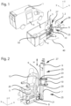
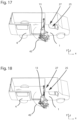
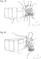
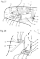
- FIGS. 1-20 various views of a first embodiment of a motor vehicle according to the invention are shown, in which the platform lift system is installed in the area of a lateral vehicle opening - here a side door 4.
- the figures show different views and positions of a motor vehicle 1 according to the invention with a platform lift system.
- the vehicle's longitudinal direction (x-direction), the vehicle's transverse direction (y-direction) and the vehicle vertical direction (z-direction) are marked in some of the figures with a corresponding coordinate system.
- the motor vehicle 1 shown is a vehicle having a front driver's cab 26 and a transport compartment 2 arranged behind it, as viewed in the vehicle's longitudinal direction.
- the transport compartment 2, which is intended in particular for the transport of patients, is separated from the driver's cab by a partition wall 3.
- the motor vehicle 1 can, for example, be an ambulance or an emergency transport vehicle.
- the motor vehicle 1 has a side door 4, which is designed here as a sliding door.
- the side door 4 is shown in the top left of the figure in Figure 1 closed and in the picture below right in Figure 1 opened. In the figure below right in Figure 1 It can be seen that a platform lift system 25 is installed in the area of the partition wall 3.
- the platform lift system 25 comprises a lifting unit 27 with a lifting element 6, which is arranged in the direction of the double arrow H in Figure 2 is arranged to be movable relative to a support element 7.
- the support element 7 is designed as a vertical support extending in the vertical direction of the vehicle.
- Part of the lifting unit 27 are also a joint 10 and a connecting element 9, which is connected to the joint 10.
- the connecting element 9 extends in the Figures 1 and 2 shown transport position of the platform lift system essentially in the vehicle vertical direction and in Vehicle transverse direction. It is designed here as a triangular flat steel element with a vertical support attached to it.
- the connecting element 9 can alternatively be designed differently, in particular as a circumferential supporting frame, as a rectangular or otherwise shaped plate, or as a supporting structure in the manner of a truss.
- the connecting element 9 is rigidly connected to a platform 8 which extends substantially in the horizontal direction, i.e. in the vehicle longitudinal direction and in the vehicle transverse direction.
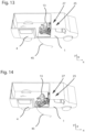
- the platform lift system 25 serves to transport a transport person 13 sitting on a transport chair 5 in a simple manner between an outside position (cf. Figures 18-20 ) outside the motor vehicle 1 and a transport position (cf. Figures 1-3 , 11 and 13 ) within the motor vehicle 1, whereby the transport person should be able to be brought into a transportable state in the transport position.
- a belt 20 with a lower belt attachment 21 and an upper belt deflection 23 is arranged on one side of the connecting element 9.
- the illustrated belt 20 is a known 3-point belt with a buckle tongue 28 attached to it.
- a belt buckle 24 is attached to a part extending from the platform 8 or from a lower Section of the connecting element 9 is attached to the holding element 29 extending obliquely upwards.
- a transport person 13 sitting on a transport chair 5 can be - as in Figure 2 shown - strapped in and fixed both inside the motor vehicle 1 and outside the motor vehicle 1 in a simple manner within the transport chair 5, because the strap 20 and the belt buckle 24 are firmly connected to the platform 8 and fixed relative to it.
- the transport chair 5 has four wheels 11 and four carrying handles 12, two of which are arranged at the front and two at the rear. This is a carrying chair well known in the industry.
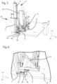
- the platform 8 in the embodiment shown has two grooves 30 serving as guides for the wheels 11, which extend in the longitudinal direction of the platform 8. Between the grooves 30, a central web 31 is formed which is raised relative to the grooves 30. In the central web 31, a slot 15 extending in the longitudinal direction of the platform 8 is formed. As in Figure 8 As can be clearly seen, the slot 15 extends from the front over part of the length of the platform to a slot end which acts as a stop 22.
- Two vertically extending coupling elements 14, which are here rod-shaped, are provided on the transport chair 5.
- Guide elements 16, here mushroom-shaped, are formed at the lower end of these coupling elements 14. These guide elements 16, in the relative arrangement shown in the figures between the transport chair 5 and the platform 8, extend through the slot 15 and ensure a positive fixation of the transport chair 5 relative to the platform 8 in the vertical and transverse directions.
- Other guide elements are also suitable, in particular those with a widened portion designed to allow for a vertical penetration and a positive connection.
- T-shaped guide elements (not shown) are mentioned in this context only as an example.
- a bolt receptacle 17 is formed on the rear of the platform 8. In the embodiment shown, this consists of an angled sheet with a circular through-opening.
- a bolt 18 is formed on the support element 7 of the lifting unit 27, which bolt extends upwards from the vehicle floor 19 in the vertical direction of the vehicle. In the embodiment shown, the bolt 18 is part of a material tab 32 fastened to the vehicle floor 19, which is firmly connected to the support element 7 of the lifting unit 27.
- the bolt receptacle 17 and the bolt 18 serve as a fixing element and fixing element receptacle for fixing the platform 8 relative to the vehicle floor 19 of the motor vehicle or relative to the support element 7 of the lifting unit 27.
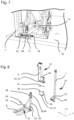
- the platform 8 only has to be removed from the Figures 5 and 6 shown position by means of the lifting unit 27, so that the bolt 18 extends through the bolt receptacle 17, as in Figure 7
- the platform is then positively secured to the vehicle floor 19 in the vehicle's longitudinal and transverse directions, particularly if rotation of the platform 8 due to gravity and/or due to a sufficiently large motor resistance of a drive motor coupled to the joint 10 is excluded.
- a locking element 64 is provided on the material tab 32. This can be designed exclusively manually, exclusively motor-driven, or in a combination of both.
- the locking element 64 is designed such that when the When the bolt receptacle 17 comes into contact with the locking element 64, the locking element is pushed into the open position until the bolt receptacle is lowered far enough for the locking element 64 to assume the closed position in such a way that the bolt receptacle is positively secured against backward movement upwards in the vehicle's vertical direction. The platform is thus positively secured in the vehicle's vertical direction.
- the locking element can be moved into the open position by motor or manually.
- motor actuation for example, it can be detected by means of a control system when the platform is to be raised using the lifting unit 27 and the open position can then be approached.
- two bolts and two bolt receptacles can also be provided to ensure a positive fixation even against rotation of the platform 8 relative to the vehicle floor 19.
- Three or more bolts and corresponding bolt receptacles can also be provided.
- FIG. 8 shows individual elements of the joint 10 in an exploded view.
- a joint receptacle 33 is formed on the lifting element 6 of the lifting unit 27. In the embodiment shown, this is formed by a lifting element bolt 34, which serves as the vertical joint receptacle rotation axis 35.
- the lifting element bolt 34 serves to receive a first bolt receptacle 36 of a joint body 37, which in this embodiment is designed as a plate-like element with two cylindrical through-holes.
- the joint body 37 has a second pin receptacle 38 at its opposite end.
- the second pin receptacle 38 serves to receive a platform pin 39, which serves as the vertical platform rotation axis 40.
- the platform pin 39 is formed on a vertically extending platform support 49, which is firmly connected to the support element 7.
- the platform 8 is therefore pivotally mounted about both the vertical joint receiving axis of rotation 35 and the vertical platform axis of rotation 40 due to the double joint as described above.
- a coupling rod 41 is additionally provided, which is pivotally mounted on the one hand about a stationary coupling rod lifting element rotation axis 42 fixed to the lifting element 6 and on the other hand about a stationary coupling rod platform rotation axis 43 fixed to the platform.
- the arrangement of the coupling rod 41 is selected such that the interaction of the double joint with the joint body 37 and the bolts 34, 39 on the one hand and the coupling rod 41 with the associated rotation axes 42, 43 on the other hand results in a forced guidance, ie a movement of the platform between the transport position (cf. Fig. 11 and 13 ) and the outside position (cf. Fig. 18-20 ) on a predetermined, forced path, which is outlined by the traverse line 45.
- the travel line 45 corresponds to the curve on which the Figure 13 the corner point of the platform 8 marked by the arrow 46.
- the travel line 45 has - starting from the transport position - an arcuate initial section with a relatively large radius, which then merges into a middle section with the opposite curvature and a small radius and ends in an almost curvature-free final section.
- the travel line 45 is selected so that the Platform 8 with a transport person 13 sitting thereon can be pivoted horizontally through the side door 4 into the outward position without contact, even if - as shown in the figures - the feet protrude at least partially beyond the front end of the platform. Operating errors that could lead to unintentional contact of the transport person 13 with the elements surrounding the door opening are thus practically eliminated - especially if no motor drive is provided for the horizontal pivoting.
- the joint 10 with the joint body 37 which functionally connects the lifting element 6 and the platform 8 to one another, is thus a central part of a separately designed horizontal displacement device 50 of this embodiment.
- the additional purely vertical movement possibility of the platform 8 by the lifting unit 27 with the lifting element 6 is decoupled from the horizontal movement possibility.
- the lifting unit 6, which is decoupled from the horizontal displacement device 50 in this respect, is used or employed both for moving the platform from the roadway level to the vehicle floor level and for a positively locking fastening of the platform 8 relative to the vehicle floor by means of bolts 18 and bolt receptacle 17.
- the transport chair 5 with a transport person 13 sitting on it can be designed as a unit fixed relative to each other from the Figure 8 shown transport position into the Figure 10 This can be done manually if no motor drive is provided or by means of a suitable drive.
- the platform 8 can be raised by means of the lifting unit 32 until the bolt is disengaged from the bolt receptacle 17.
- the platform 8 can then be pivoted into the outward position with the transport chair 5. It is particularly advantageous if the lifting unit is designed to lower the platform in the outward position to roadway level, in order to then push the transport chair 5 from the platform 8 onto the roadway or sidewalk using the wheels 11 and move it to a destination.
- joint body 37 and the boom 44 are in the transport position, as in the Figures 2 and 9 shown in a compressed position. They are then arranged one behind the other and thus folded.
- the platform 8 In the external position, the platform 8 is further moved into a position completely outside the motor vehicle 1, which makes it possible to lower the platform 8 with a transport person 13 sitting thereon in a transport chair 5 by means of the lifting unit 27 from the level of the vehicle floor 19 to the roadway level and vice versa to raise it again.
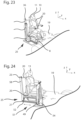
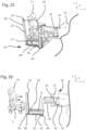
- the Figures 21 to 29 The platform lift system 25 shown is intended for the area of a rear opening 47 of a motor vehicle 1.
- the rear opening 47 can be closed via two rear doors 48.
- FIG. 21 to 23 A transport person 13 sitting on a transport chair 5 is shown in various views in a transport position.
- the transport chair 5 is arranged on a platform 8, which - unless otherwise described below - essentially corresponds in its structural design to the platform 8 described above.
- the transport person 13 is strapped in by means of a belt 20 attached to the platform 8 and is thus fixed relative to the transport chair 5.
- the platform 8 is functionally coupled with a horizontal travel device 50 and can thus be moved - starting from the Figures 21 to 23 shown transport position - move in the vehicle's longitudinal direction (x-direction) according to the double arrow 50.
- the horizontal displacement device 50 in the embodiment shown is essentially formed by a profile element 52, which is part of the platform 30, and a complementarily designed profile rail 53.
- the profile element 52 is provided as a C-shaped profile on the side of the platform 30.
- the profile rail 53 is designed as a vehicle-fixed H-shaped profile and is dimensioned such that a positive sliding connection to the profile element 52 can be established.
- the platform lift system 25 is essentially formed by a ground anchor 54 firmly anchored to the vehicle floor 19, two cantilever arms 55, 56 of a parallel kinematic system which are rotatably coupled to a platform support 49, and a thrust element 57.
- a belt support 58 extending in the vertical direction.
- a flap 59 is provided on the rear of the platform 8. This flap 59 is pivotably attached to the platform 8 and serves in the folded-down state, as for example in Fig. 28 shown as a ramp. When folded up, as for example in Fig. 27 As shown, the flap 59 serves to secure a transport chair 5 against unintentional rolling off the platform 8.
- a bolt 60 protruding transversely from the side of the platform 8 is formed, which, in the transport position shown, interacts with a hold-down device 61 firmly anchored to the vehicle floor 19.
- the hold-down device 61 By driving under the hold-down device 61, the platform is positively secured in the vehicle's vertical direction and forward in the vehicle's longitudinal direction. In the vehicle's transverse direction, the platform 8 is additionally positively secured due to the interaction between the profile element 52 and the profile rail 53.
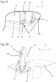
- FIGS. 30 and 31 show a further embodiment in which a kinematic system with a long ground anchor cantilever arm 62 and a long platform cantilever arm 63 is provided, wherein the ground anchor cantilever arm 62 is pivotally arranged on the ground anchor 54 and the platform cantilever arm 63 is provided as a connecting link between the ground anchor cantilever arm 62 and the platform and is pivotally arranged relative to both elements.
- the horizontal displacement device 50 and the lifting unit 27 are merged into a common unit.
- the platform 8 is moved simultaneously on a guided path in the vertical direction and in the longitudinal direction in order to move the platform between the transport position and the external position.
Landscapes
- Engineering & Computer Science (AREA)
- Transportation (AREA)
- Mechanical Engineering (AREA)
- Health & Medical Sciences (AREA)
- Public Health (AREA)
- Life Sciences & Earth Sciences (AREA)
- Animal Behavior & Ethology (AREA)
- General Health & Medical Sciences (AREA)
- Veterinary Medicine (AREA)
- Handcart (AREA)
Claims (13)
- Véhicule automobile (1) avec un système de levage de plate-forme (25), qui présente au moins les éléments suivants : une plate-forme (8) destinée à recevoir un siège de transport (5) sur lequel est assise une personne à transporter (13), une unité de levage (27) pour effectuer des mouvements relatifs verticaux de la plate-forme (8) afin de soulever et d'abaisser la plate-forme (8) et un dispositif de déplacement horizontal (50) pour effectuer des mouvements relatifs horizontaux entre la plate-forme (8) et l'unité de levage (27), la plate-forme (8) pouvant être déplacée au moyen de l'unité de levage (27) et/ou du dispositif de déplacement horizontal (50) entre une position extérieure à l'extérieur du véhicule automobile (1) et une position de transport à l'intérieur du véhicule automobile (1), caractérisé en ce que
le dispositif de déplacement horizontal (50) et/ou l'unité de levage (27) présentent un guidage forcé pour pouvoir déplacer la plate-forme (8) sur une trajectoire au moins partiellement guidée de manière forcée, le guidage forcé étant formé par une articulation multiple (36, 37, 38) avec une barre de couplage (41) reliée fonctionnellement et/ou une cinématique parallèle (54, 55, 56, 57). - Véhicule automobile (1) selon la revendication précédente, caractérisé en ce que le système de levage de plate-forme (25) comprend un siège de transport (5) et au moins un élément de fixation est prévu pour fixer le siège de transport (5) et/ou la plate-forme (8) par rapport au plancher du véhicule (19), afin de fixer la plate-forme (8) et/ou le siège de transport (5) dans la position de transport par rapport au plancher du véhicule (19).
- Véhicule automobile (1) selon la revendication précédente, caractérisé en ce que l'unité de levage (27) elle-même est réalisée sous forme d'élément de fixation et/ou le dispositif de déplacement horizontal (50) est réalisé sous forme d'élément de fixation et/ou un système composé d'au moins un boulon (18, 60) et d'un logement de boulon (17) correspondant ou d'un serre-flan (61) correspondant est réalisé sous forme d'élément de fixation.
- Véhicule automobile (1) selon l'une quelconque des revendications 2 ou 3 précédentes, caractérisé en ce qu'un boulon de guidage (18) est réalisé sur le siège de transport (5) et une fente (15) correspondant au boulon de guidage (18) est réalisée sur la plate-forme (8) et/ou dans le plancher du véhicule (19), une liaison par complémentarité de forme dans la direction verticale du véhicule pouvant être établie par introduction et déplacement du boulon de guidage (18) dans la fente (15).
- Véhicule automobile (1) selon l'une quelconque des revendications 2 à 4 précédentes, caractérisé en ce que l'unité de levage (27) et/ou le dispositif de déplacement horizontal (50) est réalisé de telle sorte que la plate-forme (8) peut être amenée dans une position de transport dans laquelle le siège de transport (5) et/ou la plate-forme (8) est fixé(e) par complémentarité de forme et/ou par adhérence au moins dans une direction par rapport au plancher du véhicule (19).
- Véhicule automobile (1) selon l'une quelconque des revendications précédentes, caractérisé en ce qu'il est prévu en tant que guidage forcé un agencement de pivotement.
- Véhicule automobile (1) selon l'une quelconque des revendications précédentes, caractérisé en ce que l'unité de levage (27) et/ou l'unité de déplacement horizontal sont agencées sur une structure de support commune.
- Véhicule automobile (1) selon l'une quelconque des revendications précédentes, caractérisé en ce qu'au moins une ceinture (20) et/ou au moins une boucle de ceinture (24) pour fixer une ceinture (20) est agencée sur la plate-forme (8) ou de manière solidaire du véhicule dans le véhicule automobile (1).
- Véhicule automobile (1) selon l'une quelconque des revendications précédentes, caractérisé en ce que la plate-forme (8) est solidaire d'un élément de liaison (9) s'étendant dans la direction verticale, qui est relié à l'unité de levage (27) et/ou au dispositif de déplacement horizontal (50).
- Véhicule automobile (1) selon l'une quelconque des revendications 2 à 9 précédentes, caractérisé en ce qu'une nervure centrale surélevée (31) et/ou une fente (15) est réalisée sur la plate-forme (8) pour coopérer avec un élément d'accouplement (14) du siège de transport (5).
- Véhicule automobile (1) selon l'une quelconque des revendications 2 à 10 précédentes, caractérisé en ce que des goulottes de déplacement (30) servant de guide pour les roues du siège de transport (5) sont réalisées sur la plate-forme (8) et/ou une structure de type griffe est réalisée sur la plate-forme (8) pour coopérer avec une structure fonctionnelle installée du côté du plancher du véhicule (19) pour fixer et/ou guider la plate-forme (8) par rapport au plancher du véhicule (19).
- Véhicule automobile (1) selon l'une quelconque des deux revendications précédentes, caractérisé en ce que l'unité de levage (27) est montée de manière solidaire au véhicule et/ou est agencée sur une paroi de séparation (3) à proximité d'une porte latérale (4) ou sur une paroi latérale à proximité d'une ouverture arrière (47) du véhicule automobile (1).
- Procédé pour charger et décharger en toute sécurité ainsi que pour transporter des personnes à transporter (13) assises sur un siège de transport (5) à l'aide d'un véhicule automobile (1) selon l'une quelconque des revendications 1 à 12, caractérisé en ce que pour le chargement et le transport, le siège de transport (5) avec la personne à transporter (13) assise dessus est d'abord positionné sur la plate-forme (8) et la plate-forme (8) est ensuite déplacée de la position extérieure à l'extérieur du véhicule automobile (1) dans une position de transport à l'intérieur du véhicule automobile (1).
Priority Applications (1)
| Application Number | Priority Date | Filing Date | Title |
|---|---|---|---|
| EP21177806.3A EP4098236B1 (fr) | 2021-06-04 | 2021-06-04 | Véhicule automobile pourvu de système de plate-forme élévatrice permettant de charger et de décharger, ainsi que de transporter des personnes de manière sécurisée, ainsi que procédé |
Applications Claiming Priority (1)
| Application Number | Priority Date | Filing Date | Title |
|---|---|---|---|
| EP21177806.3A EP4098236B1 (fr) | 2021-06-04 | 2021-06-04 | Véhicule automobile pourvu de système de plate-forme élévatrice permettant de charger et de décharger, ainsi que de transporter des personnes de manière sécurisée, ainsi que procédé |
Publications (3)
| Publication Number | Publication Date |
|---|---|
| EP4098236A1 EP4098236A1 (fr) | 2022-12-07 |
| EP4098236C0 EP4098236C0 (fr) | 2025-05-21 |
| EP4098236B1 true EP4098236B1 (fr) | 2025-05-21 |
Family
ID=76283644
Family Applications (1)
| Application Number | Title | Priority Date | Filing Date |
|---|---|---|---|
| EP21177806.3A Active EP4098236B1 (fr) | 2021-06-04 | 2021-06-04 | Véhicule automobile pourvu de système de plate-forme élévatrice permettant de charger et de décharger, ainsi que de transporter des personnes de manière sécurisée, ainsi que procédé |
Country Status (1)
| Country | Link |
|---|---|
| EP (1) | EP4098236B1 (fr) |
Family Cites Families (6)
| Publication number | Priority date | Publication date | Assignee | Title |
|---|---|---|---|---|
| DE2928607A1 (de) | 1979-07-14 | 1981-02-19 | Bernhard Bruns Maschf | Um eine lotrechte achse schwenkbare, heb- und senkbare hubplattform zum be- und entladen eines lastkraftwagens |
| US4664584A (en) * | 1985-03-21 | 1987-05-12 | The Braun Corporation | Rotary wheelchair lift |
| US5308214A (en) * | 1993-03-08 | 1994-05-03 | Chrysler Corporation | Wheelchair lift apparatus |
| US20070194607A1 (en) * | 2006-02-03 | 2007-08-23 | Simon Dudai | Motor Vehicle Chair System for Physically Disabled Persons |
| US10052244B2 (en) * | 2015-12-31 | 2018-08-21 | Access-Able Designs, Inc. | Vehicle mounted extender apparatus |
| EP3615375A1 (fr) * | 2017-04-26 | 2020-03-04 | OnScene Solutions, LLC | Ensemble coulissant d'abaissement de chargement |
-
2021
- 2021-06-04 EP EP21177806.3A patent/EP4098236B1/fr active Active
Also Published As
| Publication number | Publication date |
|---|---|
| EP4098236C0 (fr) | 2025-05-21 |
| EP4098236A1 (fr) | 2022-12-07 |
Similar Documents
| Publication | Publication Date | Title |
|---|---|---|
| DE68904115T2 (de) | Autonomer modul fuer die intensivpflege und reanimation. | |
| DE69120035T2 (de) | Wohncontainer mit streckbarem Innenraum | |
| DE69216823T2 (de) | Sich automatisch anpassendes befestigungssystem für fahrbare kästen und dergleichen | |
| DE68929186T2 (de) | Fahrzeuge und Ladebordwände | |
| EP0146029B1 (fr) | Véhicule franchissant des escaliers | |
| EP0689954B1 (fr) | Aménagement de siège, notamment pour le compartiment de chargement ou de passenger d'un véhicule automobile | |
| DE3630513C2 (de) | Faltrollstuhl | |
| EP0784916B1 (fr) | Véhicule pour le transport d'un outil, en particulier un outil roulant | |
| DE202021003972U1 (de) | Kraftfahrzeug mit Plattformlift-System zum sicheren Ein- und Ausladen sowie zum Befördern von Transportpersonen | |
| DE1194715B (de) | Vorrichtung zum Auf- und Abladen grosser, wagenkastenartiger Behaelter auf Fahrzeuge | |
| EP1842721A2 (fr) | Echelle de lit surélevé pour véhicules | |
| DE102009004525A1 (de) | Fangvorrichtung für einen Rollstuhl in einem Fahrzeug, insbesondere Schienenfahrzeug | |
| DE69707917T2 (de) | Fahrzeugausrüstung zur transferierung und befestigung eines in einen rollstuhl umwandelaren sitzes | |
| EP4098236B1 (fr) | Véhicule automobile pourvu de système de plate-forme élévatrice permettant de charger et de décharger, ainsi que de transporter des personnes de manière sécurisée, ainsi que procédé | |
| EP2308442A1 (fr) | Lit pour malades et pour les soins avec élément anti-basculant | |
| EP3974281B1 (fr) | Dispositif de montée pour un véhicule | |
| EP1777100A1 (fr) | Système de dossier | |
| EP0429033A1 (fr) | Escalier pour passagers d'avions | |
| DE10122578A1 (de) | Badewannenlifter | |
| DE19841599C2 (de) | Kraftfahrzeugsitz | |
| DE102011018618B4 (de) | Einstieghilfe | |
| DE202021003975U1 (de) | Plattformlift-System zum sicheren Transport von Personen in einem Kraftfahrzeug sowie Kraftfahrzeug mit einem solchen Plattformlift-System | |
| EP4237278B1 (fr) | Siège de véhicule | |
| DE10105701C2 (de) | Hub- und Senkeinrichtung für einen Autotransporter und einen Autotransport-Anhänger | |
| EP0213394B1 (fr) | Tracteur à chenilles pour escalier |
Legal Events
| Date | Code | Title | Description |
|---|---|---|---|
| PUAI | Public reference made under article 153(3) epc to a published international application that has entered the european phase |
Free format text: ORIGINAL CODE: 0009012 |
|
| STAA | Information on the status of an ep patent application or granted ep patent |
Free format text: STATUS: THE APPLICATION HAS BEEN PUBLISHED |
|
| AK | Designated contracting states |
Kind code of ref document: A1 Designated state(s): AL AT BE BG CH CY CZ DE DK EE ES FI FR GB GR HR HU IE IS IT LI LT LU LV MC MK MT NL NO PL PT RO RS SE SI SK SM TR |
|
| STAA | Information on the status of an ep patent application or granted ep patent |
Free format text: STATUS: REQUEST FOR EXAMINATION WAS MADE |
|
| 17P | Request for examination filed |
Effective date: 20230124 |
|
| RBV | Designated contracting states (corrected) |
Designated state(s): AL AT BE BG CH CY CZ DE DK EE ES FI FR GB GR HR HU IE IS IT LI LT LU LV MC MK MT NL NO PL PT RO RS SE SI SK SM TR |
|
| GRAP | Despatch of communication of intention to grant a patent |
Free format text: ORIGINAL CODE: EPIDOSNIGR1 |
|
| STAA | Information on the status of an ep patent application or granted ep patent |
Free format text: STATUS: GRANT OF PATENT IS INTENDED |
|
| INTG | Intention to grant announced |
Effective date: 20241220 |
|
| GRAS | Grant fee paid |
Free format text: ORIGINAL CODE: EPIDOSNIGR3 |
|
| GRAA | (expected) grant |
Free format text: ORIGINAL CODE: 0009210 |
|
| STAA | Information on the status of an ep patent application or granted ep patent |
Free format text: STATUS: THE PATENT HAS BEEN GRANTED |
|
| AK | Designated contracting states |
Kind code of ref document: B1 Designated state(s): AL AT BE BG CH CY CZ DE DK EE ES FI FR GB GR HR HU IE IS IT LI LT LU LV MC MK MT NL NO PL PT RO RS SE SI SK SM TR |
|
| REG | Reference to a national code |
Ref country code: GB Ref legal event code: FG4D Free format text: NOT ENGLISH |
|
| REG | Reference to a national code |
Ref country code: CH Ref legal event code: EP |
|
| REG | Reference to a national code |
Ref country code: DE Ref legal event code: R096 Ref document number: 502021007509 Country of ref document: DE |
|
| REG | Reference to a national code |
Ref country code: IE Ref legal event code: FG4D Free format text: LANGUAGE OF EP DOCUMENT: GERMAN |
|
| U01 | Request for unitary effect filed |
Effective date: 20250618 |
|
| PGFP | Annual fee paid to national office [announced via postgrant information from national office to epo] |
Ref country code: AT Payment date: 20250721 Year of fee payment: 5 |
|
| U07 | Unitary effect registered |
Designated state(s): AT BE BG DE DK EE FI FR IT LT LU LV MT NL PT RO SE SI Effective date: 20250627 |
|
| U20 | Renewal fee for the european patent with unitary effect paid |
Year of fee payment: 5 Effective date: 20250627 |
|
| PG25 | Lapsed in a contracting state [announced via postgrant information from national office to epo] |
Ref country code: ES Free format text: LAPSE BECAUSE OF FAILURE TO SUBMIT A TRANSLATION OF THE DESCRIPTION OR TO PAY THE FEE WITHIN THE PRESCRIBED TIME-LIMIT Effective date: 20250521 |
|
| PG25 | Lapsed in a contracting state [announced via postgrant information from national office to epo] |
Ref country code: GR Free format text: LAPSE BECAUSE OF FAILURE TO SUBMIT A TRANSLATION OF THE DESCRIPTION OR TO PAY THE FEE WITHIN THE PRESCRIBED TIME-LIMIT Effective date: 20250822 Ref country code: NO Free format text: LAPSE BECAUSE OF FAILURE TO SUBMIT A TRANSLATION OF THE DESCRIPTION OR TO PAY THE FEE WITHIN THE PRESCRIBED TIME-LIMIT Effective date: 20250821 |
|
| PG25 | Lapsed in a contracting state [announced via postgrant information from national office to epo] |
Ref country code: PL Free format text: LAPSE BECAUSE OF FAILURE TO SUBMIT A TRANSLATION OF THE DESCRIPTION OR TO PAY THE FEE WITHIN THE PRESCRIBED TIME-LIMIT Effective date: 20250521 |
|
| PG25 | Lapsed in a contracting state [announced via postgrant information from national office to epo] |
Ref country code: HR Free format text: LAPSE BECAUSE OF FAILURE TO SUBMIT A TRANSLATION OF THE DESCRIPTION OR TO PAY THE FEE WITHIN THE PRESCRIBED TIME-LIMIT Effective date: 20250521 |
|
| PG25 | Lapsed in a contracting state [announced via postgrant information from national office to epo] |
Ref country code: RS Free format text: LAPSE BECAUSE OF FAILURE TO SUBMIT A TRANSLATION OF THE DESCRIPTION OR TO PAY THE FEE WITHIN THE PRESCRIBED TIME-LIMIT Effective date: 20250821 |
|
| PG25 | Lapsed in a contracting state [announced via postgrant information from national office to epo] |
Ref country code: IS Free format text: LAPSE BECAUSE OF FAILURE TO SUBMIT A TRANSLATION OF THE DESCRIPTION OR TO PAY THE FEE WITHIN THE PRESCRIBED TIME-LIMIT Effective date: 20250921 |
|
| PG25 | Lapsed in a contracting state [announced via postgrant information from national office to epo] |
Ref country code: SM Free format text: LAPSE BECAUSE OF FAILURE TO SUBMIT A TRANSLATION OF THE DESCRIPTION OR TO PAY THE FEE WITHIN THE PRESCRIBED TIME-LIMIT Effective date: 20250521 |
|
| PG25 | Lapsed in a contracting state [announced via postgrant information from national office to epo] |
Ref country code: CZ Free format text: LAPSE BECAUSE OF FAILURE TO SUBMIT A TRANSLATION OF THE DESCRIPTION OR TO PAY THE FEE WITHIN THE PRESCRIBED TIME-LIMIT Effective date: 20250521 |
|
| PG25 | Lapsed in a contracting state [announced via postgrant information from national office to epo] |
Ref country code: SK Free format text: LAPSE BECAUSE OF FAILURE TO SUBMIT A TRANSLATION OF THE DESCRIPTION OR TO PAY THE FEE WITHIN THE PRESCRIBED TIME-LIMIT Effective date: 20250521 |
|
| REG | Reference to a national code |
Ref country code: CH Ref legal event code: H13 Free format text: ST27 STATUS EVENT CODE: U-0-0-H10-H13 (AS PROVIDED BY THE NATIONAL OFFICE) Effective date: 20260127 |
|
| PG25 | Lapsed in a contracting state [announced via postgrant information from national office to epo] |
Ref country code: MC Free format text: LAPSE BECAUSE OF FAILURE TO SUBMIT A TRANSLATION OF THE DESCRIPTION OR TO PAY THE FEE WITHIN THE PRESCRIBED TIME-LIMIT Effective date: 20250521 |
|
| PLBE | No opposition filed within time limit |
Free format text: ORIGINAL CODE: 0009261 |
|
| STAA | Information on the status of an ep patent application or granted ep patent |
Free format text: STATUS: NO OPPOSITION FILED WITHIN TIME LIMIT |
|
| REG | Reference to a national code |
Ref country code: CH Ref legal event code: L10 Free format text: ST27 STATUS EVENT CODE: U-0-0-L10-L00 (AS PROVIDED BY THE NATIONAL OFFICE) Effective date: 20260402 |
|
| PG25 | Lapsed in a contracting state [announced via postgrant information from national office to epo] |
Ref country code: IE Free format text: LAPSE BECAUSE OF NON-PAYMENT OF DUE FEES Effective date: 20250604 |
|
| PG25 | Lapsed in a contracting state [announced via postgrant information from national office to epo] |
Ref country code: CH Free format text: LAPSE BECAUSE OF NON-PAYMENT OF DUE FEES Effective date: 20250630 |
|
| 26N | No opposition filed |
Effective date: 20260224 |