EP4098331A1 - Raquette de badminton - Google Patents
Raquette de badminton Download PDFInfo
- Publication number
- EP4098331A1 EP4098331A1 EP21756746.0A EP21756746A EP4098331A1 EP 4098331 A1 EP4098331 A1 EP 4098331A1 EP 21756746 A EP21756746 A EP 21756746A EP 4098331 A1 EP4098331 A1 EP 4098331A1
- Authority
- EP
- European Patent Office
- Prior art keywords
- shaft
- flexural rigidity
- rigidity value
- measurement point
- sheet
- Prior art date
- Legal status (The legal status is an assumption and is not a legal conclusion. Google has not performed a legal analysis and makes no representation as to the accuracy of the status listed.)
- Withdrawn
Links
- 238000005259 measurement Methods 0.000 claims abstract description 96
- 239000012783 reinforcing fiber Substances 0.000 claims description 6
- 229920000049 Carbon (fiber) Polymers 0.000 description 74
- 239000004917 carbon fiber Substances 0.000 description 74
- 229920005989 resin Polymers 0.000 description 18
- 239000011347 resin Substances 0.000 description 18
- 238000009826 distribution Methods 0.000 description 15
- 238000004519 manufacturing process Methods 0.000 description 13
- VNWKTOKETHGBQD-UHFFFAOYSA-N methane Chemical compound C VNWKTOKETHGBQD-UHFFFAOYSA-N 0.000 description 13
- 239000000835 fiber Substances 0.000 description 8
- 238000000034 method Methods 0.000 description 6
- 230000000052 comparative effect Effects 0.000 description 4
- 239000011159 matrix material Substances 0.000 description 4
- 238000004804 winding Methods 0.000 description 4
- 238000012360 testing method Methods 0.000 description 3
- 238000010586 diagram Methods 0.000 description 2
- 230000000694 effects Effects 0.000 description 2
- 239000003822 epoxy resin Substances 0.000 description 2
- 238000011156 evaluation Methods 0.000 description 2
- 239000003365 glass fiber Substances 0.000 description 2
- 238000010438 heat treatment Methods 0.000 description 2
- 230000002093 peripheral effect Effects 0.000 description 2
- 229920000647 polyepoxide Polymers 0.000 description 2
- XQUPVDVFXZDTLT-UHFFFAOYSA-N 1-[4-[[4-(2,5-dioxopyrrol-1-yl)phenyl]methyl]phenyl]pyrrole-2,5-dione Chemical compound O=C1C=CC(=O)N1C(C=C1)=CC=C1CC1=CC=C(N2C(C=CC2=O)=O)C=C1 XQUPVDVFXZDTLT-UHFFFAOYSA-N 0.000 description 1
- 239000004696 Poly ether ether ketone Substances 0.000 description 1
- 239000004952 Polyamide Substances 0.000 description 1
- 239000004695 Polyether sulfone Substances 0.000 description 1
- 239000004697 Polyetherimide Substances 0.000 description 1
- 239000004734 Polyphenylene sulfide Substances 0.000 description 1
- 239000004743 Polypropylene Substances 0.000 description 1
- 239000000853 adhesive Substances 0.000 description 1
- 230000001070 adhesive effect Effects 0.000 description 1
- 239000004760 aramid Substances 0.000 description 1
- 229920006231 aramid fiber Polymers 0.000 description 1
- 238000005452 bending Methods 0.000 description 1
- 230000015572 biosynthetic process Effects 0.000 description 1
- 238000003754 machining Methods 0.000 description 1
- 239000002184 metal Substances 0.000 description 1
- 238000010422 painting Methods 0.000 description 1
- 239000005011 phenolic resin Substances 0.000 description 1
- 238000005498 polishing Methods 0.000 description 1
- 229920003192 poly(bis maleimide) Polymers 0.000 description 1
- 229920002647 polyamide Polymers 0.000 description 1
- 229920006393 polyether sulfone Polymers 0.000 description 1
- 229920002530 polyetherether ketone Polymers 0.000 description 1
- 229920001601 polyetherimide Polymers 0.000 description 1
- 229920001721 polyimide Polymers 0.000 description 1
- 239000009719 polyimide resin Substances 0.000 description 1
- 229920000069 polyphenylene sulfide Polymers 0.000 description 1
- -1 polypropylene Polymers 0.000 description 1
- 229920001155 polypropylene Polymers 0.000 description 1
- 238000003825 pressing Methods 0.000 description 1
- 229920005992 thermoplastic resin Polymers 0.000 description 1
- 229920001187 thermosetting polymer Polymers 0.000 description 1
Images




Classifications
-
- A—HUMAN NECESSITIES
- A63—SPORTS; GAMES; AMUSEMENTS
- A63B—APPARATUS FOR PHYSICAL TRAINING, GYMNASTICS, SWIMMING, CLIMBING, OR FENCING; BALL GAMES; TRAINING EQUIPMENT
- A63B49/00—Stringed rackets, e.g. for tennis
-
- A—HUMAN NECESSITIES
- A63—SPORTS; GAMES; AMUSEMENTS
- A63B—APPARATUS FOR PHYSICAL TRAINING, GYMNASTICS, SWIMMING, CLIMBING, OR FENCING; BALL GAMES; TRAINING EQUIPMENT
- A63B60/00—Details or accessories of golf clubs, bats, rackets or the like
- A63B60/0081—Substantially flexible shafts; Hinged shafts
-
- A—HUMAN NECESSITIES
- A63—SPORTS; GAMES; AMUSEMENTS
- A63B—APPARATUS FOR PHYSICAL TRAINING, GYMNASTICS, SWIMMING, CLIMBING, OR FENCING; BALL GAMES; TRAINING EQUIPMENT
- A63B2102/00—Application of clubs, bats, rackets or the like to the sporting activity ; particular sports involving the use of balls and clubs, bats, rackets, or the like
- A63B2102/04—Badminton
-
- A—HUMAN NECESSITIES
- A63—SPORTS; GAMES; AMUSEMENTS
- A63B—APPARATUS FOR PHYSICAL TRAINING, GYMNASTICS, SWIMMING, CLIMBING, OR FENCING; BALL GAMES; TRAINING EQUIPMENT
- A63B2209/00—Characteristics of used materials
- A63B2209/02—Characteristics of used materials with reinforcing fibres, e.g. carbon, polyamide fibres
-
- A—HUMAN NECESSITIES
- A63—SPORTS; GAMES; AMUSEMENTS
- A63B—APPARATUS FOR PHYSICAL TRAINING, GYMNASTICS, SWIMMING, CLIMBING, OR FENCING; BALL GAMES; TRAINING EQUIPMENT
- A63B2209/00—Characteristics of used materials
- A63B2209/02—Characteristics of used materials with reinforcing fibres, e.g. carbon, polyamide fibres
- A63B2209/023—Long, oriented fibres, e.g. wound filaments, woven fabrics, mats
-
- A—HUMAN NECESSITIES
- A63—SPORTS; GAMES; AMUSEMENTS
- A63B—APPARATUS FOR PHYSICAL TRAINING, GYMNASTICS, SWIMMING, CLIMBING, OR FENCING; BALL GAMES; TRAINING EQUIPMENT
- A63B60/00—Details or accessories of golf clubs, bats, rackets or the like
- A63B60/42—Devices for measuring, verifying, correcting or customising the inherent characteristics of golf clubs, bats, rackets or the like, e.g. measuring the maximum torque a batting shaft can withstand
Definitions
- the present invention relates to a badminton racket.
- the present invention relates to improvements to the shaft of the racket.
- a badminton racket includes a frame, a string, and a shaft. The player shots a shuttlecock with the racket. The shaft is deformed upon the shot.
- Chinese Patent Publication No. 107115641 discloses a racket including a shaft including a bending portion having a small diameter.
- the player performs various types of shots.
- the player performs shots such as smash, lob, cut, and clear.
- the smash is a shot aimed at causing the opponent player to fail to receive the shuttlecock.
- the player is required to have the skill to allow the shuttlecock to fly at an intended height.
- the player wants to stabilize the trajectory of the shuttlecock in the smash.
- the shaft In the smash, the shaft is significantly deflected in the in-plane direction and in the out-of-plane direction.
- the player wants to stabilize the trajectory of the shuttlecock also for shots which are other than the smash and in which the shaft is deflected in both the in-plane and out-of-plane directions.
- An object of the present invention is to provide a badminton racket suitable for shots in which the shaft of the racket is significantly deflected in both the in-plane and out-of-plane directions.
- a badminton racket according to the present invention includes:
- a ratio (EI(2)/EI(1)) of the flexural rigidity value EI(2) to the flexural rigidity value EI(1) is not less than 1.10.
- a ratio (EI(2)/EI(4)) of the flexural rigidity value EI(2) to the flexural rigidity value EI(4) is not less than 1.10.
- a ratio (EI(3)/EI(1)) of the flexural rigidity value EI(3) to the flexural rigidity value EI(1) is not less than 1.10.
- a ratio (EI(3)/EI(4)) of the flexural rigidity value EI(3) to the flexural rigidity value EI(4) is not less than 1.10.
- a difference (EI(2) - EI(1)) between the flexural rigidity value EI(2) and the flexural rigidity value EI(1) is not less than 0.50 Nm 2 .
- a difference (EI(2) - EI(4)) between the flexural rigidity value EI(2) and the flexural rigidity value EI(4) is not less than 0.50 Nm 2 .
- a difference (EI(3) - EI(1)) between the flexural rigidity value EI(3) and the flexural rigidity value EI(1) is not less than 0.50 Nm 2 .
- a difference (EI(3) - EI(4)) between the flexural rigidity value EI(3) and the flexural rigidity value EI(4) is not less than 0.50 Nm 2 .
- the shaft may have a hollow structure.
- an inner diameter of the shaft is substantially constant from the first measurement point to the fourth measurement point.
- an outer diameter of the shaft is substantially constant from the first measurement point to the fourth measurement point.
- a ratio (W2/W1) of a weight W2 of the shaft in a zone from the second measurement point to the third measurement point to a weight W1 of the shaft in a zone from the first measurement point to the second measurement point is not less than 0.95 and not greater than 1.05.
- a ratio (W2/W3) of the weight W2 of the shaft in the zone from the second measurement point to the third measurement point to a weight W3 of the shaft in a zone from the third measurement point to the fourth measurement point is not less than 0.95 and not greater than 1.05.
- the shaft includes a fiber-reinforced layer.
- the fiber-reinforced layer is located in a zone including the second and third measurement points and not including the first and fourth measurement points in an axial direction of the shaft.
- the fiber-reinforced layer includes a plurality of reinforcing fibers oriented substantially in the axial direction.
- a player using the badminton racket according to the present invention can easily perform shots in which the shaft is significantly deflected in both the in-plane and out-of-plane directions.
- the racket can contribute to winning badminton games.
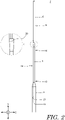
- FIGS. 1 and 2 show a badminton racket 2.
- the racket 2 includes a shaft 4, a frame 6, a grip 8, and a string 10.
- the arrow X represents the width direction
- the arrow Y represents the axial direction
- the arrow Z represents the thickness direction.
- the shaft 4 includes a butt portion 12, a middle portion 14, and a tip portion 16.
- the shaft 4 further includes a butt end 18 and a tip end 20.
- the shaft 4 is hollow.
- the shaft 4 is formed from a fiber-reinforced resin.
- the fiber-reinforced resin includes a resin matrix and a large number of reinforcing fibers.
- the shaft 4 includes a plurality of fiber-reinforced layers (which will be described in detail later).
- Examples of the base resin of the shaft 4 include: thermosetting resins such as epoxy resin, bismaleimide resin, polyimide, and phenol resin; and thermoplastic resins such as polyether ether ketone, polyethersulfone, polyetherimide, polyphenylene sulfide, polyamide, and polypropylene.
- Epoxy resin is particularly suitable as the resin of the shaft 4.
- Examples of the reinforcing fibers of the shaft 4 include carbon fibers, metal fibers, glass fibers, and aramid fibers. Carbon fibers are particularly suitable as the fibers of the shaft 4. Different kinds of fibers may be used in combination.
- the frame 6 is ring-shaped and hollow.
- the frame 6 is formed from a fiber-reinforced resin. Any of the resins as mentioned for the base resin of the shaft 4 can be used as the base resin of the fiber-reinforced resin. Any of the fibers as mentioned for the reinforcing fibers of the shaft 4 can be used as the reinforcing fibers of the fiber-reinforced resin.
- the frame 6 is firmly joined to the tip end 20 of the shaft 4.
- the grip 8 includes a hole 21 extending in the axial direction (Y direction).
- the butt end 18 and its vicinity of the shaft 4 are inserted into the hole 21.
- the inner peripheral surface of the hole 21 and the outer peripheral surface of the shaft 4 are bonded with an adhesive.
- the string 10 is strung on the frame 6.
- the string 10 is placed along the width direction X and the axial direction Y.
- the portions of the string 10 that extend along the width direction X are referred to as transverse threads 22.
- the portions of the string 10 that extend along the axial direction Y are referred to as longitudinal threads 24.
- the plurality of transverse threads 22 and the plurality of longitudinal threads 24 form a face 26.
- the face 26 extends generally along the X-Y plane.
- the reference sign L represents the length of the exposed portion of the shaft 4.
- the length L is usually not less than 150 mm and not greater than 210 mm.
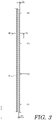
- FIG. 3 is an enlarged cross-sectional view showing a part of the shaft 4 of the racket 2 of FIG. 1 .
- FIG. 4 is an enlarged cross-sectional view taken along the line IV-IV of FIG. 3 .
- the shaft 4 is hollow.
- the cross-section of the shaft 4 is circular. In other words, the shaft 4 is in the shape of a cylindrical tube.
- the arrow Di represents the inner diameter of the shaft 4.
- the inner diameter Di is typically not less than 3 mm and not greater than 10 mm.
- the arrow Do represents the outer diameter of the shaft 4.
- the outer diameter Do is typically not less than 5 mm and not greater than 15 mm.
- the shaft 4 is formed from a fiber-reinforced resin.
- the shaft 4 can be produced by a sheet winding method. In the sheet winding method, a plurality of prepregs are wound on a mandrel. Each prepreg includes a plurality of fibers and a matrix resin. The matrix resin is uncured.
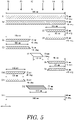
- FIG. 5 is a developed view showing a prepreg arrangement for the shaft 4 of the racket 2 of FIG. 1 .
- the prepreg arrangement includes 13 prepregs (sheets). Specifically, the prepreg arrangement includes a first sheet S1, a second sheet S2, a third sheet S3, a fourth sheet S4, a fifth sheet S5, a sixth sheet S6, a seventh sheet S7, an eighth sheet S8, a ninth sheet S9, a tenth sheet S10, an eleventh sheet 11, a twelfth sheet 12, and a thirteenth sheet 13.
- a plurality of fiber-reinforced layers are formed from the prepregs by a method described later.
- a first fiber-reinforced layer is formed from the first sheet S1
- a second fiber-reinforced layer is formed from the second sheet S2
- a third fiber-reinforced layer is formed from the third sheet S3
- a fourth fiber-reinforced layer is formed from the fourth sheet S4
- a fifth fiber-reinforced layer is formed from the fifth sheet S5
- a sixth fiber-reinforced layer is formed from the sixth sheet S6
- a seventh fiber-reinforced layer is formed from the seventh sheet S7
- an eighth fiber-reinforced layer is formed from the eighth sheet S8
- a ninth fiber-reinforced layer is formed from the ninth sheet S9
- a tenth fiber-reinforced layer is formed from the tenth sheet S10
- an eleventh fiber-reinforced layer is formed from the eleventh sheet S11
- a twelfth fiber-reinforced layer is formed from the twelfth sheet S12
- the left-right direction in FIG. 5 is the axial direction of the shaft 4.
- the locations of the butt end 18 and tip end 20 are indicated by arrows.
- the locations of four measurement points P1, P2, P3, and P4 described later are also indicated by arrows.
- the reduction scale in the left-right direction (axial direction) is not equal to the reduction scale in the up-down direction.
- the first sheet S1 extends over the entirety of the shaft 4.
- the first sheet S1 is generally rectangular.
- the first sheet S1 includes a plurality of carbon fibers arranged in parallel.
- the direction in which each of the carbon fibers extends is inclined with respect to the axial direction.
- the direction in which each carbon fiber extends forms an angle of not less than 30° and not greater than 60° with the axial direction. In the present embodiment, the angle is 45°.
- the first sheet S1 is 70 mm wide and 340 mm long.
- the second sheet S2 extends over the entirety of the shaft 4.
- the second sheet S2 is generally rectangular.
- the second sheet S2 includes a plurality of carbon fibers arranged in parallel.
- the direction in which each of the carbon fibers extends is inclined with respect to the axial direction.
- the direction in which each carbon fiber extends forms an angle of not less than -60° and not greater than -30° with the axial direction. In the present embodiment, the angle is -45°.
- the second sheet S2 is 70 mm wide and 340 mm long.
- the direction of the inclination of the carbon fibers in the second sheet S2 is opposite to the direction of the inclination of the carbon fibers in the first sheet S1.
- the direction of the inclination of the carbon fibers in the second fiber-reinforced layer is opposite to the direction of the inclination of the carbon fibers in the first fiber-reinforced layer.
- a bias structure is achieved by the first and second fiber-reinforced layers.
- the first and second fiber-reinforced layers contribute to the flexural rigidity and torsional rigidity of the shaft 4.
- the first and second fiber-reinforced layers particularly contribute to the torsional rigidity of the shaft 4.
- the third sheet S3 is localized towards the tip end 20 of the shaft 4.
- the third sheet S3 is generally trapezoidal.
- the third sheet S3 includes a plurality of carbon fibers arranged in parallel.
- the direction in which each of the carbon fibers extends is inclined with respect to the axial direction.
- the direction in which each carbon fiber extends forms an angle of not less than 30° and not greater than 60° with the axial direction. In the present embodiment, the angle is 45°.
- the third sheet S3 is 35 mm wide, 105 mm long on the upper base, and 115 mm long on the lower base.
- the fourth sheet S4 is localized towards the tip end 20 of the shaft 4. In the axial direction, the location of the fourth sheet S4 is the same as the location of the third sheet S3.
- the fourth sheet S4 is generally trapezoidal.
- the fourth sheet S4 includes a plurality of carbon fibers arranged in parallel. The direction in which each of the carbon fibers extends is inclined with respect to the axial direction. The direction in which each carbon fiber extends forms an angle of not less than -60° and not greater than -30° with the axial direction. In the present embodiment, the angle is -45°.
- the fourth sheet S4 is 35 mm wide, 105 mm long on the upper base, and 115 mm long on the lower base.
- the direction of the inclination of the carbon fibers in the fourth sheet S4 is opposite to the direction of the inclination of the carbon fibers in the third sheet S3.
- the direction of the inclination of the carbon fibers in the fourth fiber-reinforced layer is opposite to the direction of the inclination of the carbon fibers in the third fiber-reinforced layer.
- a bias structure is achieved by the third and fourth fiber-reinforced layers.
- the third and fourth fiber-reinforced layers contribute to the flexural rigidity and torsional rigidity of the middle portion 14 and tip portion 16.
- the third and fourth fiber-reinforced layers particularly contribute to the torsional rigidity of the middle portion 14 and tip portion 16.
- the fifth sheet S5 is localized towards the butt end 18 of the shaft 4.
- the fifth sheet S5 is generally trapezoidal.
- the fifth sheet S5 includes a plurality of carbon fibers arranged in parallel.
- the direction in which each of the carbon fibers extends is inclined with respect to the axial direction.
- the direction in which each carbon fiber extends forms an angle of not less than 30° and not greater than 60° with the axial direction. In the present embodiment, the angle is 45°.
- the fifth sheet S5 is 35 mm wide, 155 mm long on the upper base, and 165 mm long on the lower base.
- the sixth sheet S6 is localized towards the butt end 18 of the shaft 4. In the axial direction, the location of the sixth sheet S6 is the same as the location of the fifth sheet S5.
- the sixth sheet S6 is generally trapezoidal.
- the sixth sheet S6 includes a plurality of carbon fibers arranged in parallel. The direction in which each of the carbon fibers extends is inclined with respect to the axial direction. The direction in which each carbon fiber extends forms an angle of not less than -60° and not greater than -30° with the axial direction. In the present embodiment, the angle is -45°.
- the sixth sheet S6 is 35 mm wide, 155 mm long on the upper base, and 165 mm long on the lower base.
- the direction of the inclination of the carbon fibers in the sixth sheet S6 is opposite to the direction of the inclination of the carbon fibers in the fifth sheet S5.
- the direction of the inclination of the carbon fibers in the sixth fiber-reinforced layer is opposite to the direction of the inclination of the carbon fibers in the fifth fiber-reinforced layer.
- a bias structure is achieved by the fifth and sixth fiber-reinforced layers.
- the fifth and sixth fiber-reinforced layers contribute to the flexural rigidity and torsional rigidity of the butt portion 12 and middle portion 14.
- the fifth and sixth fiber-reinforced layers particularly contribute to the torsional rigidity of the butt portion 12 and middle portion 14.
- the seventh sheet S7 is localized in the middle portion 14 of the shaft 4.
- the seventh sheet S7 is generally in the shape of a parallelogram.
- the seventh sheet S7 includes a plurality of carbon fibers arranged in parallel.
- the direction in which each of the carbon fibers extends is the same as the axial direction. In other words, the direction in which each carbon fiber extends forms an angle of substantially 0° with the axial direction.
- the seventh sheet S7 is 70 mm wide and 70 mm long.
- the carbon fibers contained in the seventh sheet S7 are oriented substantially in the axial direction.
- the carbon fibers are oriented substantially in the axial direction also in the seventh fiber-reinforced layer.
- the structure in which the carbon fibers are oriented substantially in the axial direction is herein referred to as a "straight structure".
- the seventh fiber-reinforced layer has a straight structure.
- the seventh sheet S7 is located in a zone including the second and third measurement points P2 and P3 and not including the first and fourth measurement points P1 and P4 in the axial direction.
- the seventh fiber-reinforced layer is also located in the zone including the second and third measurement points P2 and P3 and not including the first and fourth measurement points P1 and P4 in the axial direction.
- the seventh fiber-reinforced layer particularly contributes to the flexural rigidity of the middle portion 14.
- the eighth sheet S8 is localized towards the tip end 20 of the shaft 4.
- the eighth sheet S8 is generally trapezoidal.
- the eighth sheet S8 includes a plurality of carbon fibers arranged in parallel.
- the direction in which each of the carbon fibers extends is inclined with respect to the axial direction.
- the direction in which each carbon fiber extends forms an angle of not less than 30° and not greater than 60° with the axial direction. In the present embodiment, the angle is 45°.
- the eighth sheet S8 is 35 mm wide, 85 mm long on the upper base, and 95 mm long on the lower base.
- the ninth sheet S9 is localized towards the tip end 20 of the shaft 4. In the axial direction, the location of the ninth sheet S9 is the same as the location of the eighth sheet S8.
- the ninth sheet S9 is generally trapezoidal.
- the ninth sheet S9 includes a plurality of carbon fibers arranged in parallel. The direction in which each of the carbon fibers extends is inclined with respect to the axial direction. The direction in which each carbon fiber extends forms an angle of not less than -60° and not greater than -30° with the axial direction. In the present embodiment, the angle is -45°.
- the ninth sheet S9 is 35 mm wide, 85 mm long on the upper base, and 95 mm long on the lower base.
- the direction of the inclination of the carbon fibers in the ninth sheet S9 is opposite to the direction of the inclination of the carbon fibers in the eighth sheet S8.
- the direction of the inclination of the carbon fibers in the ninth fiber-reinforced layer is opposite to the direction of the inclination of the carbon fibers in the eighth fiber-reinforced layer.
- a bias structure is achieved by the eighth and ninth fiber-reinforced layers.
- the eighth and ninth fiber-reinforced layers contribute to the flexural rigidity and torsional rigidity of the tip portion 16.
- the eighth and ninth fiber-reinforced layers particularly contribute to the torsional rigidity of the tip portion 16.
- the tenth sheet S10 is localized towards the butt end 18 of the shaft 4.
- the tenth sheet S10 is generally trapezoidal.
- the tenth sheet S10 includes a plurality of carbon fibers arranged in parallel.
- the direction in which each of the carbon fibers extends is inclined with respect to the axial direction.
- the direction in which each carbon fiber extends forms an angle of not less than 30° and not greater than 60° with the axial direction. In the present embodiment, the angle is 45°.
- the tenth sheet S10 is 35 mm wide, 135 mm long on the upper base, and 145 mm long on the lower base.
- the eleventh sheet S11 is localized towards the butt end 18 of the shaft 4. In the axial direction, the location of the eleventh sheet S11 is the same as the location of the tenth sheet S10.
- the eleventh sheet S11 is generally trapezoidal.
- the eleventh sheet S11 includes a plurality of carbon fibers arranged in parallel. The direction in which each of the carbon fibers extends is inclined with respect to the axial direction. The direction in which each carbon fiber extends forms an angle of not less than -60° and not greater than -30° with the axial direction. In the present embodiment, the angle is -45°.
- the eleventh sheet S11 is 35 mm wide, 135 mm long on the upper base, and 145 mm long on the lower base.
- the direction of the inclination of the carbon fibers in the eleventh sheet S11 is opposite to the direction of the inclination of the carbon fibers in the tenth sheet S10.
- the direction of the inclination of the carbon fibers in the eleventh fiber-reinforced layer is opposite to the direction of the inclination of the carbon fibers in the tenth fiber-reinforced layer.
- a bias structure is achieved by the tenth and eleventh fiber-reinforced layers.
- the tenth and eleventh fiber-reinforced layers contribute to the flexural rigidity and torsional rigidity of the butt portion 12.
- the tenth and eleventh fiber-reinforced layers particularly contribute to the torsional rigidity of the butt portion 12.
- the twelfth sheet S12 is localized in the middle portion 14 of the shaft 4.
- the twelfth sheet S12 is generally in the shape of a parallelogram.
- the twelfth sheet S12 includes a plurality of carbon fibers arranged in parallel.
- the direction in which each of the carbon fibers extends is the same as the axial direction. In other words, the direction in which each carbon fiber extends forms an angle of substantially 0° with the axial direction.
- the twelfth sheet S12 is 70 mm wide and 110 mm long.
- the carbon fibers contained in the twelfth sheet S12 are oriented substantially in the axial direction.
- the carbon fibers are oriented substantially in the axial direction also in the twelfth fiber-reinforced layer.
- the twelfth fiber-reinforced layer has a straight structure.
- the carbon fibers are subjected to a strong tension. The tension acts to prevent further deflection of the shaft 4.
- the carbon fibers contribute to the flexural rigidity of the shaft 4.
- the twelfth sheet S12 is located in a zone including the second and third measurement points P2 and P3 and not including the first and fourth measurement points P1 and P4 in the axial direction.
- the twelfth fiber-reinforced layer is also located in the zone including the second and third measurement points P2 and P3 and not including the first and fourth measurement points P1 and P4 in the axial direction.
- the twelfth fiber-reinforced layer particularly contributes to the flexural rigidity of the middle portion 14.
- the thirteenth sheet S13 extends over the entirety of the shaft 4.
- the thirteenth sheet S13 is generally rectangular.
- the thirteenth sheet S13 includes a plurality of carbon fibers arranged in parallel.
- the direction in which each of the carbon fibers extends is the same as the axial direction. In other words, the direction in which each carbon fiber extends forms an angle of substantially 0° with the axial direction.
- the thirteenth sheet S13 is 40 mm wide and 340 mm long.
- the carbon fibers contained in the thirteenth sheet S13 are oriented substantially in the axial direction.
- the carbon fibers are oriented substantially in the axial direction also in the thirteenth fiber-reinforced layer.
- the thirteenth fiber-reinforced layer has a straight structure.
- the first, second, and thirteenth fiber-reinforced layers extend from the butt end 18 to the tip end 20. These fiber-reinforced layers can contribute to the durability of the shaft 4.
- the sheets shown in FIG. 5 are sequentially wound on a mandrel.
- a stack of the first and second sheets S1 and S2 may be wound on the mandrel.
- a stack of the third and fourth sheets S3 and S4 may be wound on the mandrel.
- a stack of the fifth and sixth sheets S5 and S6 may be wound on the mandrel.
- a stack of the eighth and ninth sheets S8 and S9 may be wound on the mandrel.
- a stack of the tenth and eleventh sheets S10 and S11 may be wound on the mandrel.
- another sheet may be wound on the mandrel.
- An example of the other sheet is a sheet containing glass fibers.
- a wrapping tape is further wound on the above sheets.
- the mandrel, prepregs (sheets S1 to S13), and wrapping tape are heated by means such as an oven.
- the heating fluidizes the matrix resin. Further heating induces a curing reaction of the resin, as a result of which a shaped product is obtained.
- the shaped product is subjected to various processes such as end face machining, polishing, and painting, and thus the shaft 4 is completed.
- FIG. 6 is a schematic diagram showing a method of measuring a flexural rigidity value EI of the shaft 4 of the racket 2 of FIG. 1 .
- FIG. 6 shows the measurement at a measurement point P located at a distance L1 from the grip 8.
- the shaft 4 is supported from below at first and second support points 28 and 30.
- the distance from the measurement point P to the first support point 28 is 30 mm.
- the distance from the measurement point P to the second support point 30 is 30 mm.
- the measurement is performed using a universal testing machine (manufactured by INTESCO Co., Ltd. under the product name "2020").
- the testing machine includes an indenter 32.
- the indenter 32 is in the shape of a hemisphere.
- the radius of curvature of the hemisphere is 20 mm.
- the indenter 32 gradually descends at a speed of 2 mm/min.
- the indenter 32 comes into contact with the measurement point P and presses the shaft 4.
- the pressing causes gradual deflection of the shaft 4.
- the amount of deflection B (m) of the shaft 4 is measured at the moment when the load applied to the shaft 4 by the indenter 32 reaches 100 N.
- the amount of deflection B is substituted into the following equation to calculate the flexural rigidity value EI (Nm 2 ).
- EI F ⁇ L 2 3 / 48 ⁇ B
- F is the load (N)
- L2 is the distance (m) between the two support points
- B is the amount of deflection (m).
- the load F is 100 N
- the distance L2 is 0.06 m.
- the flexural rigidity value EI of the shaft 4 may be measured in the absence of the grip 8 and frame 6.
- the flexural rigidity values EI are measured at the first, second, third, and fourth measurement points P1, P2, P3, and P4.
- the distance L1 from the grip 8 to each measurement point is as follows.
- the flexural rigidity value EI(1) at the first measurement point P1 is 3.82 Nm 2
- the flexural rigidity value EI(2) at the second measurement point P2 is 5.51 Nm 2
- the flexural rigidity value EI(3) at the third measurement point P3 is 5.74 Nm 2
- the flexural rigidity value EI(4) at the fourth measurement point P4 is 3.58 Nm 2 .
- the flexural rigidity distribution of the shaft 4 is shown in the graph of FIG. 7 .
- the flexural rigidity value EI(2) at the second measurement point P2 is greater than the flexural rigidity value EI(1) at the first measurement point P1 and the flexural rigidity value EI(4) at the fourth measurement point P4. Furthermore, in the shaft 4, the flexural rigidity value EI(3) at the third measurement point P3 is greater than the flexural rigidity value EI(1) at the first measurement point P1 and the flexural rigidity value EI(4) at the fourth measurement point P4. In the shaft 4, the following four inequality relations are established.
- the shaft 4 has a rigidity distribution with an upward-convex profile.
- the seventh fiber-reinforced layer is located in a zone including the second and third measurement points P2 and P3 and not including the first and fourth measurement points P1 and P4 in the axial direction.
- the twelfth fiber-reinforced layer is located in a zone including the second and third measurement points P2 and P3 and not including the first and fourth measurement points P1 and P4 in the axial direction.
- This layer structure can attain a flexural rigidity distribution with an upward-convex profile.
- Another layer structure can also attain a flexural rigidity distribution with an upward-convex profile.
- Local presence of a fiber-reinforced layer having a straight structure in the middle portion 14 can result in a flexural rigidity distribution with an upward-convex profile.
- the shaft 4 having a flexural rigidity distribution with an upward-convex profile is suitable for the smash.
- the player who performs the smash using the racket 2 can easily achieve an intended trajectory of the shuttlecock. With the use of the racket 2, the variation in the height of the trajectory of the shuttlecock in the smash is small.
- the reason why the racket 2 according to the present invention is suitable for the smash is that the flexural rigidity distribution shown in FIG. 7 matches the deformation behavior of the shaft 4 in the smash.
- the shaft 4 is significantly deflected in the in-plane direction (direction along the X-Y plane) and in the out-of-plane direction (Z direction).
- the racket 2 according to the present invention is suitable also for shots which are other than the smash and in which the shaft 4 is significantly deflected in both the in-plane and out-of-plane directions.
- the flexural rigidity distribution can be adjusted by changing the location of the prepregs, the number of the prepregs, the width of the prepregs, the length of the prepregs, the angle of the fibers, the weight per unit area of the fibers, and the elastic modulus of the fibers.
- the ratio (EI(2)/EI(1)) of the flexural rigidity value EI(2) to the flexural rigidity value EI(1) is preferably not less than 1.10, more preferably not less than 1.22, and particularly preferably not less than 1.30. From the viewpoint of ease of production of the shaft 4, the ratio is preferably not greater than 2.50.
- the ratio (EI(2)/EI(4)) of the flexural rigidity value EI(2) to the flexural rigidity value EI(4) is preferably not less than 1.10, more preferably not less than 1.33, and particularly preferably not less than 1.45. From the viewpoint of ease of production of the shaft 4, the ratio is preferably not greater than 3.00.
- the ratio (EI(3)/EI(1)) of the flexural rigidity value EI(3) to the flexural rigidity value EI(1) is preferably not less than 1.10, more preferably not less than 1.24, and particularly preferably not less than 1.45. From the viewpoint of ease of production of the shaft 4, the ratio is preferably not greater than 3.00.
- the ratio (EI(3)/EI(4)) of the flexural rigidity value EI(3) to the flexural rigidity value EI(4) is preferably not less than 1.10, more preferably not less than 1.35, and particularly preferably not less than 1.50. From the viewpoint of ease of production of the shaft 4, the ratio is preferably not greater than 3.00.
- the ratio (EI(1)/EI(4)) is preferably not less than 0.5 and not greater than 2.0.
- the ratio (EI(2)/EI(3)) is preferably not less than 0.5 and not greater than 2.0.
- the difference (EI(2) - EI(1)) between the flexural rigidity value EI(2) and the flexural rigidity value EI(1) is preferably not less than 0.50 Nm 2 , more preferably not less than 0.91 Nm 2 , and particularly preferably not less than 1.30 Nm 2 . From the viewpoint of ease of production of the shaft 4, the difference is preferably not greater than 3.5 Nm 2 .
- the difference (EI(2) - EI(4)) between the flexural rigidity value EI(2) and the flexural rigidity value EI(4) is preferably not less than 0.50 Nm 2 , more preferably not less than 1.24 Nm 2 , and particularly preferably not less than 1.50 Nm 2 . From the viewpoint of ease of production of the shaft 4, the difference is preferably not greater than 3.5 Nm 2 .
- the difference (EI(3) - EI(1)) between the flexural rigidity value EI(3) and the flexural rigidity value EI(1) is preferably not less than 0.50 Nm 2 , more preferably not less than 0.99 Nm 2 , and particularly preferably not less than 1.50 Nm 2 . From the viewpoint of ease of production of the shaft 4, the difference is preferably not greater than 3.5 Nm 2 .
- the difference (EI(3) - EI(4)) between the flexural rigidity value EI(3) and the flexural rigidity value EI(4) is preferably not less than 0.50 Nm 2 , more preferably not less than 1.32 Nm 2 , and particularly preferably not less than 1.70 Nm 2 . From the viewpoint of ease of production of the shaft 4, the difference is preferably not greater than 3.5 Nm 2 .
- FIG. 3 shows the first, second, third, and fourth measurement points P1, P2, P3, and P4.
- the inner diameter Di of the shaft 4 is substantially constant from the first measurement point P1 to the fourth measurement point P4.
- the shaft 4 can be produced using a mandrel having a simple shape. In the production of the shaft 4, the winding of the prepregs is easy.
- the shaft 4 may have a slight variation in the inner diameter Di due to, for example, production error.
- the ratio (Di1/Di2) of the maximum inner diameter Di1 to the minimum inner diameter Di2 in the zone from the first measurement point P1 to the fourth measurement point P4 is preferably not greater than 1.10, more preferably not greater than 1.05, and particularly preferably not greater than 1.03.
- the ratio (Di1/Di2) is ideally 1.00.
- the outer diameter Do of the shaft 4 is substantially constant from the first measurement point P1 to the fourth measurement point P4.
- the shaft 4 can be produced using a mandrel having a simple shape. In the production of the shaft 4, the winding of the prepregs is easy.
- the shaft 4 may have a slight variation in the outer diameter Do due to, for example, production error.
- the ratio (Do1/Do2) of the maximum outer diameter Do1 to the minimum outer diameter Do2 in the zone from the first measurement point P1 to the fourth measurement point P4 is preferably not greater than 1.10, more preferably not greater than 1.05, and particularly preferably not greater than 1.03.
- the ratio (Do1/Di2) is ideally 1.00.
- the ratio (W2/W1) of the weight W2 of the shaft 4 in the zone from the second measurement point P2 to the second measurement point P3 to the weight W1 of the shaft 4 in the zone from the first measurement point P1 to the second measurement point P2 is preferably not less than 0.95 and not greater than 1.05.
- the ratio (W2/W3) of the weight W2 to the weight W3 of the shaft 4 in the zone from the third measurement point P3 to the fourth measurement point P4 is preferably not less than 0.95 and not greater than 1.05.
- Such a shaft 4 is free from a significant local increase in weight. The player can swing the racket 2 including the shaft 4 without feeling discomfort.
- the ratios (W2/W1) and (W2/W3) are more preferably not less than 0.97 and not greater than 1.03 and particularly preferably not less than 0.98 and not greater than 1.02.
- the flexural rigidity distribution is not adjusted by thickness adjustment. In the shaft 4, the flexural rigidity distribution is not adjusted by opening formation. The shaft 4 is less likely to suffer stress concentration. The shaft 4 has excellent durability.
- FIGS. 1 to 6 A badminton racket as shown in FIGS. 1 to 6 was produced.
- the flexural rigidity values EI of the racket are shown in Table 1 below and in FIG. 7 .
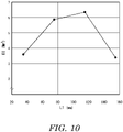
- Badminton rackets of Examples 2 and 3 and Comparative Example were obtained in the same manner as the badminton racket of Example 1, except for changing the prepreg arrangement.
- the flexural rigidity values EI of the rackets are shown in Table 1 below and in FIGS. 8 to 10 .
- a shuttlecock was launched by a launching machine.
- a player was caused to perform smash on the shuttlecock, and a video image of the trajectory of the shuttlecock was captured.
- the image was analyzed to measure the height at which the shuttlecock passed above the net.
- the measurement was conducted six times, and an average height Hav, a maximum height Hmax, and a minimum height Hmin were determined. The results are shown in Table 1 below.
- the badminton racket according to the present invention is suitable for players who play in a style involving frequent use of smash.
- the racket is suitable also for players who play in other styles.
Landscapes
- Health & Medical Sciences (AREA)
- General Health & Medical Sciences (AREA)
- Physical Education & Sports Medicine (AREA)
- Golf Clubs (AREA)
Applications Claiming Priority (2)
| Application Number | Priority Date | Filing Date | Title |
|---|---|---|---|
| JP2020025155A JP7424095B2 (ja) | 2020-02-18 | 2020-02-18 | バドミントンラケット |
| PCT/JP2021/001551 WO2021166518A1 (fr) | 2020-02-18 | 2021-01-19 | Raquette de badminton |
Publications (2)
| Publication Number | Publication Date |
|---|---|
| EP4098331A1 true EP4098331A1 (fr) | 2022-12-07 |
| EP4098331A4 EP4098331A4 (fr) | 2024-02-21 |
Family
ID=77392093
Family Applications (1)
| Application Number | Title | Priority Date | Filing Date |
|---|---|---|---|
| EP21756746.0A Withdrawn EP4098331A4 (fr) | 2020-02-18 | 2021-01-19 | Raquette de badminton |
Country Status (3)
| Country | Link |
|---|---|
| EP (1) | EP4098331A4 (fr) |
| JP (1) | JP7424095B2 (fr) |
| WO (1) | WO2021166518A1 (fr) |
Family Cites Families (8)
| Publication number | Priority date | Publication date | Assignee | Title |
|---|---|---|---|---|
| CN2754672Y (zh) * | 2004-12-07 | 2006-02-01 | 厦门侨兴工业有限公司 | 羽毛球拍的多段式中管 |
| JP5230835B1 (ja) * | 2012-08-31 | 2013-07-10 | グローブライド株式会社 | バドミントンラケットに用いられるシャフトを製造する方法 |
| CN204815568U (zh) * | 2015-07-28 | 2015-12-02 | 吴淑明 | 一种羽毛球拍 |
| CN205340022U (zh) * | 2015-11-26 | 2016-06-29 | 徐建昇 | 羽毛球拍中管增强结构 |
| CN107115641A (zh) | 2017-06-06 | 2017-09-01 | 邬惠林 | 拍杆具有两细管弯曲处的羽毛球拍 |
| CN107261439A (zh) * | 2017-06-24 | 2017-10-20 | 邬惠林 | 拍杆具有两处弯曲处的羽毛球拍 |
| JP7085399B2 (ja) * | 2018-04-27 | 2022-06-16 | ヨネックス株式会社 | バドミントンラケット |
| JP7326978B2 (ja) * | 2019-08-08 | 2023-08-16 | 住友ゴム工業株式会社 | バドミントンラケットの仕様決定方法及びシャフト挙動の解析方法 |
-
2020
- 2020-02-18 JP JP2020025155A patent/JP7424095B2/ja active Active
-
2021
- 2021-01-19 EP EP21756746.0A patent/EP4098331A4/fr not_active Withdrawn
- 2021-01-19 WO PCT/JP2021/001551 patent/WO2021166518A1/fr not_active Ceased
Also Published As
| Publication number | Publication date |
|---|---|
| WO2021166518A1 (fr) | 2021-08-26 |
| JP2021129633A (ja) | 2021-09-09 |
| JP7424095B2 (ja) | 2024-01-30 |
| EP4098331A4 (fr) | 2024-02-21 |
Similar Documents
| Publication | Publication Date | Title |
|---|---|---|
| US20020123392A1 (en) | Golf club shaft formed from metal-containing prepreg and non-metal fiber prepreg and method of making the same | |
| US6652389B2 (en) | Golf club shaft | |
| CN100428969C (zh) | 球类运动的球拍 | |
| EP4098331A1 (fr) | Raquette de badminton | |
| EP4098332A1 (fr) | Raquette de badminton | |
| EP4098334A1 (fr) | Raquette de badminton | |
| EP4098333A1 (fr) | Raquette de badminton | |
| EP4545155A1 (fr) | Raquette | |
| EP4656257A1 (fr) | Raquette | |
| JP7703967B2 (ja) | バドミントンラケット | |
| JP7505404B2 (ja) | バドミントンラケット | |
| JP7703966B2 (ja) | バドミントンラケット | |
| CN116685379B (zh) | 羽毛球拍 | |
| JP7505405B2 (ja) | バドミントンラケット | |
| JP2022103632A (ja) | バドミントンラケット | |
| JP2022103630A (ja) | バドミントンラケット | |
| JP7543906B2 (ja) | バドミントンラケット | |
| JP2022103631A (ja) | バドミントンラケット | |
| CN116669821B (zh) | 羽毛球拍 | |
| WO2022145199A1 (fr) | Raquette de badminton | |
| US20250367510A1 (en) | Racket | |
| JP2023044828A (ja) | バドミントンラケット | |
| JP2023044829A (ja) | バドミントンラケット |
Legal Events
| Date | Code | Title | Description |
|---|---|---|---|
| STAA | Information on the status of an ep patent application or granted ep patent |
Free format text: STATUS: THE INTERNATIONAL PUBLICATION HAS BEEN MADE |
|
| PUAI | Public reference made under article 153(3) epc to a published international application that has entered the european phase |
Free format text: ORIGINAL CODE: 0009012 |
|
| STAA | Information on the status of an ep patent application or granted ep patent |
Free format text: STATUS: REQUEST FOR EXAMINATION WAS MADE |
|
| 17P | Request for examination filed |
Effective date: 20220901 |
|
| AK | Designated contracting states |
Kind code of ref document: A1 Designated state(s): AL AT BE BG CH CY CZ DE DK EE ES FI FR GB GR HR HU IE IS IT LI LT LU LV MC MK MT NL NO PL PT RO RS SE SI SK SM TR |
|
| DAV | Request for validation of the european patent (deleted) | ||
| DAX | Request for extension of the european patent (deleted) | ||
| P01 | Opt-out of the competence of the unified patent court (upc) registered |
Effective date: 20230510 |
|
| A4 | Supplementary search report drawn up and despatched |
Effective date: 20240122 |
|
| RIC1 | Information provided on ipc code assigned before grant |
Ipc: A63B 60/00 20150101ALI20240116BHEP Ipc: A63B 102/04 20150101ALI20240116BHEP Ipc: A63B 49/00 20150101AFI20240116BHEP |
|
| STAA | Information on the status of an ep patent application or granted ep patent |
Free format text: STATUS: THE APPLICATION HAS BEEN WITHDRAWN |
|
| 18W | Application withdrawn |
Effective date: 20240712 |