EP4098498B1 - Vorrichtung zum anhängen eines anhängers an ein mit einer gelenkverbindungsstruktur versehenes zugfahrzeug - Google Patents
Vorrichtung zum anhängen eines anhängers an ein mit einer gelenkverbindungsstruktur versehenes zugfahrzeug Download PDFInfo
- Publication number
- EP4098498B1 EP4098498B1 EP22176857.5A EP22176857A EP4098498B1 EP 4098498 B1 EP4098498 B1 EP 4098498B1 EP 22176857 A EP22176857 A EP 22176857A EP 4098498 B1 EP4098498 B1 EP 4098498B1
- Authority
- EP
- European Patent Office
- Prior art keywords
- chassis
- plate
- trailer
- coupling device
- cable
- Prior art date
- Legal status (The legal status is an assumption and is not a legal conclusion. Google has not performed a legal analysis and makes no representation as to the accuracy of the status listed.)
- Active
Links
Images


Classifications
-
- B—PERFORMING OPERATIONS; TRANSPORTING
- B62—LAND VEHICLES FOR TRAVELLING OTHERWISE THAN ON RAILS
- B62D—MOTOR VEHICLES; TRAILERS
- B62D53/00—Tractor-trailer combinations; Road trains
- B62D53/04—Tractor-trailer combinations; Road trains comprising a vehicle carrying an essential part of the other vehicle's load by having supporting means for the front or rear part of the other vehicle
- B62D53/08—Fifth wheel traction couplings
- B62D53/0842—King pins
-
- B—PERFORMING OPERATIONS; TRANSPORTING
- B60—VEHICLES IN GENERAL
- B60T—VEHICLE BRAKE CONTROL SYSTEMS OR PARTS THEREOF; BRAKE CONTROL SYSTEMS OR PARTS THEREOF, IN GENERAL; ARRANGEMENT OF BRAKING ELEMENTS ON VEHICLES IN GENERAL; PORTABLE DEVICES FOR PREVENTING UNWANTED MOVEMENT OF VEHICLES; VEHICLE MODIFICATIONS TO FACILITATE COOLING OF BRAKES
- B60T13/00—Transmitting braking action from initiating means to ultimate brake actuator with power assistance or drive; Brake systems incorporating such transmitting means, e.g. air-pressure brake systems
- B60T13/02—Transmitting braking action from initiating means to ultimate brake actuator with power assistance or drive; Brake systems incorporating such transmitting means, e.g. air-pressure brake systems with mechanical assistance or drive
- B60T13/06—Transmitting braking action from initiating means to ultimate brake actuator with power assistance or drive; Brake systems incorporating such transmitting means, e.g. air-pressure brake systems with mechanical assistance or drive by inertia, e.g. flywheel
- B60T13/08—Overrun brakes
-
- B—PERFORMING OPERATIONS; TRANSPORTING
- B60—VEHICLES IN GENERAL
- B60T—VEHICLE BRAKE CONTROL SYSTEMS OR PARTS THEREOF; BRAKE CONTROL SYSTEMS OR PARTS THEREOF, IN GENERAL; ARRANGEMENT OF BRAKING ELEMENTS ON VEHICLES IN GENERAL; PORTABLE DEVICES FOR PREVENTING UNWANTED MOVEMENT OF VEHICLES; VEHICLE MODIFICATIONS TO FACILITATE COOLING OF BRAKES
- B60T7/00—Brake-action initiating means
- B60T7/12—Brake-action initiating means for automatic initiation; for initiation not subject to will of driver or passenger
- B60T7/20—Brake-action initiating means for automatic initiation; for initiation not subject to will of driver or passenger specially for trailers, e.g. in case of uncoupling of or overrunning by trailer
Definitions
- the subject of the invention is a device for attaching a trailer to a towing vehicle, in particular equipped with an articulated connection structure.
- Examples of hanging devices are known from the documents GB 1 440 577 A And WO 00/74959 A1 .
- connection between a towing vehicle (private vehicle or truck) and a trailer is generally made in two ways: by a ball joint attached to the towing vehicle to which a trailer drawbar is attached or by a plate attached to the trailer pivotally mounted on a fifth wheel mounted on the towing vehicle.
- Trailers connected to the vehicle by a ball joint - drawbar assembly are generally equipped with an inertial brake actuated by a stroke of the drawbar following the longitudinal direction of the vehicle, this stroke resulting from a relative movement of the drawbar. hitch and trailer when braking the vehicle.
- This type of connection has the disadvantage of allowing rotation of the drawbar around this longitudinal direction so that the low center of gravity of the towing vehicle cannot be used to combat the reversal of the trailer in turn.
- the plate In the case of plate-shovel connections, the plate is pivotally mounted on the saddle around a vertical axis and the saddle can pivot around a transverse axis, but rotational movements around the longitudinal direction are prohibited, which helps prevent the trailer from rolling over when turning.
- these connection systems prohibiting any longitudinal translation movement require the use of complex braking systems, generally pneumatic.
- the invention relates to a device for attaching a trailer to a towing vehicle, comprising a coupling plate equipped with a pivot extending perpendicular to the plate and intended to cooperate reversibly with a device combined coupling of the towing vehicle, characterized in that it comprises an articulated structure intended to connect the plate to a trailer chassis, the articulated connection structure comprising two links, each link being provided with a pair of joints of axes of rotation perpendicular to the plate: a first articulation mounted on the plate and a second articulation intended to be mounted on the chassis of trailer, the articulated connection structure defining a Watt parallelogram allowing movement of the pivot along a substantially rectilinear and longitudinal trajectory relative to the trailer chassis when the attachment device is mounted on the latter.
- this type of coupling plate is intended to cooperate with a fifth wheel by inserting the pivot of the plate into a corresponding receiving orifice of the fifth wheel. This type of connection thus prohibits any rotational movement around a longitudinal axis, promoting resistance to rollover in turns of the trailer equipped with the attachment device according to the invention.
- the hanging device according to the invention also has the advantage of being simple to produce and assemble, and inexpensive.
- the articulated connection structure can consist only of the two links.
- At least one of the first and second joints of each link can be a rolling joint, for example a ball or needle bearing.
- the other joints can then be elastic joints, however, in a preferred embodiment, the two joints of each link are rolling joints.
- the hooking device then has the advantage of being free of play, very low friction and very rigid in maintaining longitudinal rotation.
- each link can be connected to the plate in positions located in a plane defined by the plate near a straight line passing through the pivot, in particular the center thereof, and intended to extend in a longitudinal direction of the trailer chassis when the attachment device is mounted on the latter.
- the links can be mounted on the plate on a side opposite the pivot, for example on an upper face of the plate when the attachment device is mounted on the trailer chassis.
- the second articulation of one of the links can be located at a distance from the ends of the link, the first articulation being located at one of these ends and the other end of the link comprising a cable fixing element intended for fixing an actuation cable of an inertial braking system.
- This type of cable generally extends toward the rear of the trailer frame.
- the cable fixing element can be designed to prevent any relative translational movement between the cable and the link to which it is attached. We retain a ball joint, so that the cable does not bend, or at least a pivot connection, like on a bicycle brake handle.
- This cable fixing element may in particular allow removable fixing of the cable to facilitate its replacement.
- the invention also relates to a motor vehicle trailer chassis, characterized in that it is equipped with a hooking device according to the invention, positioned so that the trajectory of movement of the pivot extends in a direction substantially longitudinal of the chassis.
- the chassis can further comprise an inertial braking system actuated by a cable and the cable can be fixed to the cable fixing element of the hanging device.
- the links of the attachment device, and optionally the shock absorber are mounted on the plate on a side opposite the pivot, the articulated connection structure, and in particular its links, can be positioned between structural elements forming the chassis, in the thickness of the latter. This gives a hooking device mounted compactly vertically.
- the subject of the invention is a motor vehicle trailer equipped with a chassis according to the invention.
- front, rear, upper, lower refer to the front and rear directions of a trailer and its chassis, when the attachment device is mounted on the chassis.
- the X, Y, Z axes correspond respectively to the longitudinal (front to back), transverse and vertical axis of the trailer (and its chassis), the latter resting on the ground.
- the vertical direction thus corresponds to the direction of gravity.
- substantially horizontal, longitudinal or vertical we mean a direction/plane forming an angle of at most ⁇ 20°, or even at most ⁇ 10° or at most ⁇ 5°, with a horizontal direction/plane , longitudinal or vertical.
- substantially parallel, perpendicular or at right angles we mean a direction/an angle deviating by at most ⁇ 20°, or even by at most ⁇ 10° or at most ⁇ 5° from a direction/d 'a parallel, perpendicular plane or a right angle.
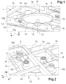
- FIG. 1 represents a chassis 1 of a trailer intended to be hooked to a towing vehicle by means of a hooking device 10 according to the invention.
- the chassis 1 is here formed of an assembly of longitudinal 1a and transverse 1b structural elements integral with each other, for example bars welded to each other.
- the attachment device 10 comprises a coupling plate 11 equipped with a pivot 12 extending perpendicular to the plate 11 and intended to cooperate reversibly with a combined coupling device of the towing vehicle.
- the combined coupling device of the towing vehicle is a fifth wheel mounted articulated to the towing vehicle around a transverse axis.
- This saddle has a flat face pierced with a through hole with a vertical axis when this face extends horizontally.
- This orifice is shaped to receive the pivot 12 of the attachment device 10 of the present invention for rotation, allowing rotation of the pivot 12 relative to the saddle around of an axis 13 perpendicular to the flat face of the saddle and to the plane defined by the plate.
- the pivot 12 is located on the side of a lower face 11a of the plate which thus rests on the top of the flat face of the saddle.
- the plate 11 is generally a flat plate in the shape of a circular shape; the invention is however not limited to a circular shape of the plate. This type of hanging system is well known and will not be described in more detail.
- the plate 11 is connected to the chassis 1 by an articulated connection structure 14 which comprises two links 15, 16.
- Each link 15, 16 has a pair of joints 151, 152; 161, 162 respectively, axes of rotation perpendicular to the plate 11, more precisely to the plane defined by the plate.
- a first articulation 151, 161 is mounted on the plate 11 and a second articulation 152, 162 is mounted on the trailer chassis 1.
- This articulated connection structure 14 defines a Watt parallelogram allowing movement of the pivot 12 along a substantially rectilinear and longitudinal trajectory relative to the chassis 1 when the attachment device 10 is mounted on the latter.
- the pivot 12 can follow a substantially rectilinear and longitudinal trajectory relative to the fixed points of the articulated connection structure 14, namely the points of connection of the latter to the chassis 1.
- substantially rectilinear trajectory is meant a rectilinear trajectory or a curved trajectory with constant or variable curvature having the largest possible radius of curvature.
- the trajectory is substantially rectilinear and longitudinal when it does not deviate by more than 5° on one side or the other of a rectilinear longitudinal trajectory of the pivot from a rest position of the device. hooking up (non-towed trailer).
- the trajectory followed by the pivot 12 is located in the plane defined by the plate and can cause a rotation of the plate 11 around its axis of rotation 13. This is not problematic when the attachment device cooperates with the harness since the pivot 12 is movable in rotation relative to the harness around this axis of rotation 13.
- the links will be able to extend in a transverse direction, as shown on the figures 1-4 , or not as shown on the figure 5 .
- This figure 5 schematically represents the plate 11 and the center I of the pivot 12 through which the axis 13 of rotation thereof passes.
- the trajectory followed by the center I then corresponds to a circle with center C, point of convergence of the straight lines passing through the links 15 and 16 in a position at rest (without traction exerted on the attachment device and the trailer).
- the radius of the circle (distance IC) must be as large as possible.
- first joints 151, 161 near a straight line D passing through the pivot 12 (through its center I) and intended to extend in the longitudinal direction of the trailer when the attachment device is mounted on the trailer chassis, as shown in all the figures. This makes it possible to maintain the previously defined center C very close to the longitudinal position of the pivot point during the movement, and thus maintain the substantially longitudinal trajectory of this pivot.
- the links will be located relative to the plate on either side of a transverse line passing through the center I of the pivot 12.
- the articulated connection structure 14 defining a Watt parallelogram the articulations 151 and 161 are at the same distance from the pivot in the longitudinal direction (in other words, these joints are equidistant in relation to a transverse line passing through the pivot), or even symmetrical in relation to the pivot, the articulation of one of the links being in front of the pivot, the articulation of the other link being behind the pivot to guarantee this substantially longitudinal trajectory.
- the links are preferably mounted on the plate 11 d a side opposite the pivot 12, typically on the upper face 11b of the plate 11.
- each link having axes perpendicular to the plane defined by the plate 11, the links can extend in a plane parallel to the plane defined by the plate 11, in particular in a rectilinear direction, facilitating their production and assembly .
- the invention is however not limited to a particular shape of the links.
- a link joint can be fixed to the chassis 1 via two support legs 2, 3 parallel to each other and perpendicular to the axis of rotation of the joint considered.
- This method of fixing makes it possible in particular to fix these joints without modifying the structure of the chassis, the joints extending here in the thickness (measured vertically) of the chassis and the support legs being secured, for example by welding, to the structural elements of the chassis.
- the links connected to the upper face 11b of the plate 11, extend between the structural elements 1a, 1b in the thickness of the chassis 1, so that a very vertically compact assembly can be obtained despite the presence of the articulated connection structure.
- the articulated connection structure 14 could also be designed so as to obtain a sufficient length of movement of the pivot for actuating a cable of an inertial braking system. Typically, this length can be of the order of 100mm ( ⁇ 50mm compared to a rest position in which the attachment device and the trailer are not subject to any traction).
- the joints of the links can be elastic joints.
- each link may have an elastic joint and a rolling joint or two rolling joints.
- the use of elastic joints for the two joints of a link is likely to allow a slight rotation of the articulated structure 14, and consequently of the plate 11, around a longitudinal axis relative to the chassis, which is not desirable to counter a trailer rollover when turning.
- Rolling joints make it possible to transmit significant torques in X, increasing the rigidity of the attachment device in relation to rotational movements around the longitudinal direction X.
- the attachment device can be used to control an inertial braking system 4.
- This type of braking system (represented schematically on the figures 3 and 4 ) is actuated in a conventional manner by means of a cable 5 by a traction movement on it generated by an inertial movement of the trailer relative to the plate 11.
- the trailer tends to advance towards the vehicle by inertia following the longitudinal direction of the chassis: a translation movement being authorized at the level of the connection between the plate 11 and the chassis thanks to the articulated connection structure 14, the plate 11 then tends to move move towards the rear of the trailer in the longitudinal direction (arrow F1 of the Figure 4 ). This movement can then be used to activate the cable.
- a cable fixing element 164 at the end 163 of one of the links, here the link 16, the other end of the link 16 supporting the first articulation 161.
- the second articulation 162 is located between the end 163 and the first articulation 161. Therefore, a movement of the plate 11, and therefore of its pivot 12, in the general direction of the arrow F1 (following the substantially rectilinear trajectory mentioned above) causes a movement of the cable fixing element 164 towards the front of the chassis in the direction of the arrow F2, and consequently a traction on the cable 5.
- the cable fixing element 164 is in the form of a plate having an orifice for the passage of the cable and provided with a device for blocking the translation of the cable.
- the invention is of course not limited to a particular embodiment of this cable fixing element and any other arrangement making it possible to block a cable in translation can be used.
- the attachment device may further comprise a shock absorber 17 mounted, preferably articulated, on the one hand on the plate 11 and on the other hand on the chassis 1.
- a shock absorber 17 is preferably also mounted on the upper face 11b of the plate. This can make it possible to limit the oscillating movements of the attachment device relative to the chassis.
Landscapes
- Engineering & Computer Science (AREA)
- Transportation (AREA)
- Mechanical Engineering (AREA)
- Physics & Mathematics (AREA)
- Fluid Mechanics (AREA)
- Chemical & Material Sciences (AREA)
- Combustion & Propulsion (AREA)
- Regulating Braking Force (AREA)
- Agricultural Machines (AREA)
Claims (10)
- Vorrichtung zum Anhängen (10) eines Anhängers an ein Zugfahrzeug, umfassend eine Kupplungsplatte (11), die mit einem Drehzapfen (12) ausgestattet ist, der sich senkrecht zu der Platte erstreckt und dazu bestimmt ist, mit einer entsprechenden Kupplungsvorrichtung des Zugfahrzeugs reversibel zusammenzuwirken, eine Gelenkverbindungsstruktur (14), die dazu bestimmt ist, die Platte (11) mit einem Anhängerfahrgestell (1) zu verbinden, wobei die Gelenkverbindungsstruktur (14) zwei Schwingarme (15, 16) umfasst, wobei jeder Schwingarm (15, 16) mit einem Gelenkpaar (151, 152; 161, 162) versehen ist, wobei ein zweites Gelenk (152, 162) jedes Gelenkpaares (151, 152; 161, 162) dazu bestimmt ist, am Anhängerfahrgestell (1) angebracht zu werden, wobei die Gelenkverbindungsstruktur (14) ein Watt-Parallelogramm definiert, das eine Bewegung des Drehzapfens (12) entlang einer Trajektorie ermöglicht, wobei die Vorrichtung zum Anhängen (10) dadurch gekennzeichnet ist, dass die Gelenke (151, 152, 161, 162) Drehachsen aufweisen, die zu der Platte (11) senkrecht sind, und ein erstes Gelenk (151, 161) jedes Gelenkpaares (151, 152; 161, 162) auf der Platte angebracht ist, und dadurch, dass die Trajektorie der Bewegung des Drehzapfens (12) im Wesentlichen gerade ist und bezüglich des Anhängerfahrgestells (1) in Längsrichtung verläuft, wenn die Vorrichtung zum Anhängen (10) an diesem Letzteren angebracht ist.
- Vorrichtung zum Anhängen (10) nach Anspruch 1, dadurch gekennzeichnet, dass mindestens eines von dem ersten und dem zweiten Gelenk jedes Schwingarmes ein Wälzgelenk ist.
- Vorrichtung zum Anhängen (10) nach Anspruch 1 oder 2, dadurch gekennzeichnet, dass die ersten Gelenke (151, 161) jedes Schwingarmes mit der Platte an Positionen verbunden sind, die sich in einer durch die Platte definierten Ebene in der Nähe einer Geraden befinden, welche durch den Drehzapfen (12) verläuft und dazu bestimmt ist, sich entlang einer Längsrichtung zu erstrecken, wenn die Vorrichtung zum Anhängen am Fahrgestell des Anhängers angebracht ist.
- Vorrichtung zum Anhängen (10) nach einem der Ansprüche 1 bis 3, dadurch gekennzeichnet, dass die Schwingarme (15, 16) an der Platte auf einer dem Drehzapfen (12) gegenüberliegenden Seite (11b) angebracht sind.
- Vorrichtung zum Anhängen (10) nach einem der Ansprüche 1 bis 4, dadurch gekennzeichnet, dass sie einen Stoßdämpfer (17) umfasst, der einerseits an der Platte (11) angebracht ist und andererseits dazu bestimmt ist, am Anhängerfahrgestell angebracht zu werden.
- Vorrichtung zum Anhängen (10) nach einem der Ansprüche 1 bis 5, dadurch gekennzeichnet, dass das zweite Gelenk (162) eines der Schwingarme sich in einem Abstand von den Enden des Schwingarmes (16) befindet, wobei das erste Gelenk (161) sich an einem dieser Enden befindet und das andere Ende (163) des Schwingarmes ein Seilbefestigungselement (164) aufweist, das zur Befestigung eines Betätigungsseils (5) eines Auflaufbremssystems bestimmt ist.
- Anhängerfahrgestell (1) eines Kraftfahrzeugs, dadurch gekennzeichnet, dass es mit einer Vorrichtung zum Anhängen (10) nach einem der Ansprüche 1 bis 6 ausgestattet ist, die derart positioniert ist, dass sich die Bewegungstrajektorie des Drehzapfens im Wesentlichen in einer Längsrichtung des Fahrgestells erstreckt.
- Anhängerfahrgestell (1) nach Anspruch 7, wenn abhängig von Anspruch 6, dadurch gekennzeichnet, dass es ein durch ein Seil (5) betätigtes Auflaufbremssystem (4) umfasst, und dadurch, dass das Seil (5) an dem Seilbefestigungselement (164) der Vorrichtung zum Anhängen befestigt ist.
- Anhängerfahrgestell (1) nach Anspruch 7 oder 8, wobei die Schwingarme (15, 16) der Vorrichtung zum Anhängen (10) an der Platte (11) auf einer dem Drehzapfen (12) gegenüberliegenden Seite angebracht sind und zwischen Strukturelementen (1a, 1b) positioniert sind, die das Fahrgestell bilden, in der Dicke dieses Letzteren.
- Kraftfahrzeuganhänger, welcher ein Fahrgestell nach einem der Ansprüche 7 bis 9 aufweist.
Applications Claiming Priority (1)
| Application Number | Priority Date | Filing Date | Title |
|---|---|---|---|
| FR2105792A FR3123592B1 (fr) | 2021-06-02 | 2021-06-02 | Dispositif d’accrochage d’une remorque à un véhicule tracteur pourvu d’une structure de liaison articulée |
Publications (2)
| Publication Number | Publication Date |
|---|---|
| EP4098498A1 EP4098498A1 (de) | 2022-12-07 |
| EP4098498B1 true EP4098498B1 (de) | 2024-07-31 |
Family
ID=76601465
Family Applications (1)
| Application Number | Title | Priority Date | Filing Date |
|---|---|---|---|
| EP22176857.5A Active EP4098498B1 (de) | 2021-06-02 | 2022-06-01 | Vorrichtung zum anhängen eines anhängers an ein mit einer gelenkverbindungsstruktur versehenes zugfahrzeug |
Country Status (2)
| Country | Link |
|---|---|
| EP (1) | EP4098498B1 (de) |
| FR (1) | FR3123592B1 (de) |
Family Cites Families (2)
| Publication number | Priority date | Publication date | Assignee | Title |
|---|---|---|---|---|
| GB1440577A (en) * | 1972-07-21 | 1976-06-23 | Smallfry Ltd | Articulated vehicle |
| GB9913005D0 (en) * | 1999-06-05 | 1999-08-04 | Univ Coventry | Bimodal vehicle |
-
2021
- 2021-06-02 FR FR2105792A patent/FR3123592B1/fr active Active
-
2022
- 2022-06-01 EP EP22176857.5A patent/EP4098498B1/de active Active
Also Published As
| Publication number | Publication date |
|---|---|
| FR3123592B1 (fr) | 2023-04-21 |
| EP4098498A1 (de) | 2022-12-07 |
| FR3123592A1 (fr) | 2022-12-09 |
Similar Documents
| Publication | Publication Date | Title |
|---|---|---|
| EP0458665B1 (de) | Hinterradaufhängung eines Kraftfahrzeugs | |
| EP1610967B1 (de) | Flexible hinterachse mit einer steuersäule und entsprechendes fahrzeug | |
| EP3691959A1 (de) | Koppelbares automotives strassenfahrzeug mit kompakter lenkung und aufhängung | |
| WO2006077346A2 (fr) | Train arriere pour bicyclette | |
| FR2775448A1 (fr) | Bati de siege d'un siege de vehicule automobile | |
| WO2018228945A1 (fr) | Dispositif d'attelage comportant quatre degres de liberte | |
| FR2672863A1 (fr) | Dispositif de colonne de direction pour vehicule automobile. | |
| EP0930183A1 (de) | Hinterradaufhängungsvorrichtung eines Kraftfahrzeuges | |
| FR2698825A1 (fr) | Dispositif de liaison entre les roues et le châssis d'un véhicule. | |
| EP0136240B1 (de) | Schwenkbare Kupplungsvorrichtung zur Kupplung eines Anhängers an ein Fahrzeug | |
| FR2813847A1 (fr) | Systeme de montage d'un garde-boue equipant une roue directrice d'un vehicule | |
| EP4098498A1 (de) | Vorrichtung zum anhängen eines anhängers an ein mit einer gelenkverbindungsstruktur versehenes zugfahrzeug | |
| WO2007116179A1 (fr) | Train arriere pour vehicule automobile | |
| FR2580998A1 (fr) | Structure d'attelage entre un vehicule tracteur et un vehicule tracte | |
| EP0683088B1 (de) | Vorderradaufhängung mit zwei Quer-Dreieckslenkern und ein mit einer solchen Radaufhängung ausgerüstetes Kraftfahrzeug | |
| FR2841870A1 (fr) | Perfectionnement a la suspension d'un vehicule inclinable a trois roues | |
| FR2558429A3 (fr) | Vehicule industriel a sellette reglable en hauteur, destine a tirer un vehicule remorque | |
| FR2625710A1 (fr) | Train arriere a action passive pour vehicule automobile et vehicule automobile equipe d'un tel train | |
| FR2788473A1 (fr) | Train arriere de vehicule automobile a ressort helicoidal et amortisseur de suspension separes | |
| EP0249539A1 (de) | Fahrzeugaufhängung für Doppelradlaufwerke, zurückfedernde Anordnung von jedem Rad des Laufwerks und Fahrzeug, das mit einer solchen Aufhängung oder zurückfedernden Anordnung ausgerüstet ist | |
| FR2848148A1 (fr) | Dispositif de suspension a bras oscillant pour remorque attelee | |
| FR2676698A1 (fr) | Timon rotatif. | |
| FR3037309A1 (fr) | Remorque semi articulee destinee a etre attelee a un vehicule tracteur et ensemble attele comprenant une telle remorque | |
| FR2710583A1 (fr) | Train avant pour véhicule automobile. | |
| FR2832101A1 (fr) | Train arriere de vehicule automobile multibras avec suspension a ressort a lame |
Legal Events
| Date | Code | Title | Description |
|---|---|---|---|
| PUAI | Public reference made under article 153(3) epc to a published international application that has entered the european phase |
Free format text: ORIGINAL CODE: 0009012 |
|
| STAA | Information on the status of an ep patent application or granted ep patent |
Free format text: STATUS: THE APPLICATION HAS BEEN PUBLISHED |
|
| AK | Designated contracting states |
Kind code of ref document: A1 Designated state(s): AL AT BE BG CH CY CZ DE DK EE ES FI FR GB GR HR HU IE IS IT LI LT LU LV MC MK MT NL NO PL PT RO RS SE SI SK SM TR |
|
| STAA | Information on the status of an ep patent application or granted ep patent |
Free format text: STATUS: REQUEST FOR EXAMINATION WAS MADE |
|
| 17P | Request for examination filed |
Effective date: 20230509 |
|
| RBV | Designated contracting states (corrected) |
Designated state(s): AL AT BE BG CH CY CZ DE DK EE ES FI FR GB GR HR HU IE IS IT LI LT LU LV MC MK MT NL NO PL PT RO RS SE SI SK SM TR |
|
| P01 | Opt-out of the competence of the unified patent court (upc) registered |
Effective date: 20230608 |
|
| GRAP | Despatch of communication of intention to grant a patent |
Free format text: ORIGINAL CODE: EPIDOSNIGR1 |
|
| STAA | Information on the status of an ep patent application or granted ep patent |
Free format text: STATUS: GRANT OF PATENT IS INTENDED |
|
| RIC1 | Information provided on ipc code assigned before grant |
Ipc: B62D 53/08 20060101ALI20231215BHEP Ipc: B60T 13/08 20060101ALI20231215BHEP Ipc: B60T 7/20 20060101AFI20231215BHEP |
|
| INTG | Intention to grant announced |
Effective date: 20240117 |
|
| GRAS | Grant fee paid |
Free format text: ORIGINAL CODE: EPIDOSNIGR3 |
|
| GRAA | (expected) grant |
Free format text: ORIGINAL CODE: 0009210 |
|
| STAA | Information on the status of an ep patent application or granted ep patent |
Free format text: STATUS: THE PATENT HAS BEEN GRANTED |
|
| AK | Designated contracting states |
Kind code of ref document: B1 Designated state(s): AL AT BE BG CH CY CZ DE DK EE ES FI FR GB GR HR HU IE IS IT LI LT LU LV MC MK MT NL NO PL PT RO RS SE SI SK SM TR |
|
| REG | Reference to a national code |
Ref country code: CH Ref legal event code: EP Ref country code: GB Ref legal event code: FG4D Free format text: NOT ENGLISH |
|
| REG | Reference to a national code |
Ref country code: DE Ref legal event code: R096 Ref document number: 602022004901 Country of ref document: DE |
|
| REG | Reference to a national code |
Ref country code: IE Ref legal event code: FG4D Free format text: LANGUAGE OF EP DOCUMENT: FRENCH |
|
| REG | Reference to a national code |
Ref country code: LT Ref legal event code: MG9D |
|
| REG | Reference to a national code |
Ref country code: NL Ref legal event code: MP Effective date: 20240731 |
|
| PG25 | Lapsed in a contracting state [announced via postgrant information from national office to epo] |
Ref country code: PT Free format text: LAPSE BECAUSE OF FAILURE TO SUBMIT A TRANSLATION OF THE DESCRIPTION OR TO PAY THE FEE WITHIN THE PRESCRIBED TIME-LIMIT Effective date: 20241202 |
|
| REG | Reference to a national code |
Ref country code: AT Ref legal event code: MK05 Ref document number: 1708182 Country of ref document: AT Kind code of ref document: T Effective date: 20240731 |
|
| PG25 | Lapsed in a contracting state [announced via postgrant information from national office to epo] |
Ref country code: PT Free format text: LAPSE BECAUSE OF FAILURE TO SUBMIT A TRANSLATION OF THE DESCRIPTION OR TO PAY THE FEE WITHIN THE PRESCRIBED TIME-LIMIT Effective date: 20241202 |
|
| PG25 | Lapsed in a contracting state [announced via postgrant information from national office to epo] |
Ref country code: NO Free format text: LAPSE BECAUSE OF FAILURE TO SUBMIT A TRANSLATION OF THE DESCRIPTION OR TO PAY THE FEE WITHIN THE PRESCRIBED TIME-LIMIT Effective date: 20241031 |
|
| PG25 | Lapsed in a contracting state [announced via postgrant information from national office to epo] |
Ref country code: FI Free format text: LAPSE BECAUSE OF FAILURE TO SUBMIT A TRANSLATION OF THE DESCRIPTION OR TO PAY THE FEE WITHIN THE PRESCRIBED TIME-LIMIT Effective date: 20240731 Ref country code: GR Free format text: LAPSE BECAUSE OF FAILURE TO SUBMIT A TRANSLATION OF THE DESCRIPTION OR TO PAY THE FEE WITHIN THE PRESCRIBED TIME-LIMIT Effective date: 20241101 Ref country code: NL Free format text: LAPSE BECAUSE OF FAILURE TO SUBMIT A TRANSLATION OF THE DESCRIPTION OR TO PAY THE FEE WITHIN THE PRESCRIBED TIME-LIMIT Effective date: 20240731 Ref country code: PL Free format text: LAPSE BECAUSE OF FAILURE TO SUBMIT A TRANSLATION OF THE DESCRIPTION OR TO PAY THE FEE WITHIN THE PRESCRIBED TIME-LIMIT Effective date: 20240731 |
|
| PG25 | Lapsed in a contracting state [announced via postgrant information from national office to epo] |
Ref country code: BG Free format text: LAPSE BECAUSE OF FAILURE TO SUBMIT A TRANSLATION OF THE DESCRIPTION OR TO PAY THE FEE WITHIN THE PRESCRIBED TIME-LIMIT Effective date: 20240731 |
|
| PG25 | Lapsed in a contracting state [announced via postgrant information from national office to epo] |
Ref country code: LV Free format text: LAPSE BECAUSE OF FAILURE TO SUBMIT A TRANSLATION OF THE DESCRIPTION OR TO PAY THE FEE WITHIN THE PRESCRIBED TIME-LIMIT Effective date: 20240731 |
|
| PG25 | Lapsed in a contracting state [announced via postgrant information from national office to epo] |
Ref country code: AT Free format text: LAPSE BECAUSE OF FAILURE TO SUBMIT A TRANSLATION OF THE DESCRIPTION OR TO PAY THE FEE WITHIN THE PRESCRIBED TIME-LIMIT Effective date: 20240731 Ref country code: IS Free format text: LAPSE BECAUSE OF FAILURE TO SUBMIT A TRANSLATION OF THE DESCRIPTION OR TO PAY THE FEE WITHIN THE PRESCRIBED TIME-LIMIT Effective date: 20241130 |
|
| PG25 | Lapsed in a contracting state [announced via postgrant information from national office to epo] |
Ref country code: HR Free format text: LAPSE BECAUSE OF FAILURE TO SUBMIT A TRANSLATION OF THE DESCRIPTION OR TO PAY THE FEE WITHIN THE PRESCRIBED TIME-LIMIT Effective date: 20240731 |
|
| PG25 | Lapsed in a contracting state [announced via postgrant information from national office to epo] |
Ref country code: ES Free format text: LAPSE BECAUSE OF FAILURE TO SUBMIT A TRANSLATION OF THE DESCRIPTION OR TO PAY THE FEE WITHIN THE PRESCRIBED TIME-LIMIT Effective date: 20240731 Ref country code: RS Free format text: LAPSE BECAUSE OF FAILURE TO SUBMIT A TRANSLATION OF THE DESCRIPTION OR TO PAY THE FEE WITHIN THE PRESCRIBED TIME-LIMIT Effective date: 20241031 |
|
| PG25 | Lapsed in a contracting state [announced via postgrant information from national office to epo] |
Ref country code: RS Free format text: LAPSE BECAUSE OF FAILURE TO SUBMIT A TRANSLATION OF THE DESCRIPTION OR TO PAY THE FEE WITHIN THE PRESCRIBED TIME-LIMIT Effective date: 20241031 Ref country code: PL Free format text: LAPSE BECAUSE OF FAILURE TO SUBMIT A TRANSLATION OF THE DESCRIPTION OR TO PAY THE FEE WITHIN THE PRESCRIBED TIME-LIMIT Effective date: 20240731 Ref country code: NO Free format text: LAPSE BECAUSE OF FAILURE TO SUBMIT A TRANSLATION OF THE DESCRIPTION OR TO PAY THE FEE WITHIN THE PRESCRIBED TIME-LIMIT Effective date: 20241031 Ref country code: NL Free format text: LAPSE BECAUSE OF FAILURE TO SUBMIT A TRANSLATION OF THE DESCRIPTION OR TO PAY THE FEE WITHIN THE PRESCRIBED TIME-LIMIT Effective date: 20240731 Ref country code: LV Free format text: LAPSE BECAUSE OF FAILURE TO SUBMIT A TRANSLATION OF THE DESCRIPTION OR TO PAY THE FEE WITHIN THE PRESCRIBED TIME-LIMIT Effective date: 20240731 Ref country code: IS Free format text: LAPSE BECAUSE OF FAILURE TO SUBMIT A TRANSLATION OF THE DESCRIPTION OR TO PAY THE FEE WITHIN THE PRESCRIBED TIME-LIMIT Effective date: 20241130 Ref country code: HR Free format text: LAPSE BECAUSE OF FAILURE TO SUBMIT A TRANSLATION OF THE DESCRIPTION OR TO PAY THE FEE WITHIN THE PRESCRIBED TIME-LIMIT Effective date: 20240731 Ref country code: GR Free format text: LAPSE BECAUSE OF FAILURE TO SUBMIT A TRANSLATION OF THE DESCRIPTION OR TO PAY THE FEE WITHIN THE PRESCRIBED TIME-LIMIT Effective date: 20241101 Ref country code: FI Free format text: LAPSE BECAUSE OF FAILURE TO SUBMIT A TRANSLATION OF THE DESCRIPTION OR TO PAY THE FEE WITHIN THE PRESCRIBED TIME-LIMIT Effective date: 20240731 Ref country code: ES Free format text: LAPSE BECAUSE OF FAILURE TO SUBMIT A TRANSLATION OF THE DESCRIPTION OR TO PAY THE FEE WITHIN THE PRESCRIBED TIME-LIMIT Effective date: 20240731 Ref country code: BG Free format text: LAPSE BECAUSE OF FAILURE TO SUBMIT A TRANSLATION OF THE DESCRIPTION OR TO PAY THE FEE WITHIN THE PRESCRIBED TIME-LIMIT Effective date: 20240731 Ref country code: AT Free format text: LAPSE BECAUSE OF FAILURE TO SUBMIT A TRANSLATION OF THE DESCRIPTION OR TO PAY THE FEE WITHIN THE PRESCRIBED TIME-LIMIT Effective date: 20240731 |
|
| PG25 | Lapsed in a contracting state [announced via postgrant information from national office to epo] |
Ref country code: DK Free format text: LAPSE BECAUSE OF FAILURE TO SUBMIT A TRANSLATION OF THE DESCRIPTION OR TO PAY THE FEE WITHIN THE PRESCRIBED TIME-LIMIT Effective date: 20240731 Ref country code: SM Free format text: LAPSE BECAUSE OF FAILURE TO SUBMIT A TRANSLATION OF THE DESCRIPTION OR TO PAY THE FEE WITHIN THE PRESCRIBED TIME-LIMIT Effective date: 20240731 Ref country code: RO Free format text: LAPSE BECAUSE OF FAILURE TO SUBMIT A TRANSLATION OF THE DESCRIPTION OR TO PAY THE FEE WITHIN THE PRESCRIBED TIME-LIMIT Effective date: 20240731 |
|
| PG25 | Lapsed in a contracting state [announced via postgrant information from national office to epo] |
Ref country code: EE Free format text: LAPSE BECAUSE OF FAILURE TO SUBMIT A TRANSLATION OF THE DESCRIPTION OR TO PAY THE FEE WITHIN THE PRESCRIBED TIME-LIMIT Effective date: 20240731 |
|
| PG25 | Lapsed in a contracting state [announced via postgrant information from national office to epo] |
Ref country code: CZ Free format text: LAPSE BECAUSE OF FAILURE TO SUBMIT A TRANSLATION OF THE DESCRIPTION OR TO PAY THE FEE WITHIN THE PRESCRIBED TIME-LIMIT Effective date: 20240731 |
|
| PG25 | Lapsed in a contracting state [announced via postgrant information from national office to epo] |
Ref country code: IT Free format text: LAPSE BECAUSE OF FAILURE TO SUBMIT A TRANSLATION OF THE DESCRIPTION OR TO PAY THE FEE WITHIN THE PRESCRIBED TIME-LIMIT Effective date: 20240731 Ref country code: SK Free format text: LAPSE BECAUSE OF FAILURE TO SUBMIT A TRANSLATION OF THE DESCRIPTION OR TO PAY THE FEE WITHIN THE PRESCRIBED TIME-LIMIT Effective date: 20240731 |
|
| REG | Reference to a national code |
Ref country code: DE Ref legal event code: R097 Ref document number: 602022004901 Country of ref document: DE |
|
| PLBE | No opposition filed within time limit |
Free format text: ORIGINAL CODE: 0009261 |
|
| STAA | Information on the status of an ep patent application or granted ep patent |
Free format text: STATUS: NO OPPOSITION FILED WITHIN TIME LIMIT |
|
| 26N | No opposition filed |
Effective date: 20250501 |
|
| PGFP | Annual fee paid to national office [announced via postgrant information from national office to epo] |
Ref country code: DE Payment date: 20250618 Year of fee payment: 4 |
|
| PGFP | Annual fee paid to national office [announced via postgrant information from national office to epo] |
Ref country code: FR Payment date: 20250627 Year of fee payment: 4 |
|
| PG25 | Lapsed in a contracting state [announced via postgrant information from national office to epo] |
Ref country code: SE Free format text: LAPSE BECAUSE OF FAILURE TO SUBMIT A TRANSLATION OF THE DESCRIPTION OR TO PAY THE FEE WITHIN THE PRESCRIBED TIME-LIMIT Effective date: 20240731 |
|
| REG | Reference to a national code |
Ref country code: CH Ref legal event code: H13 Free format text: ST27 STATUS EVENT CODE: U-0-0-H10-H13 (AS PROVIDED BY THE NATIONAL OFFICE) Effective date: 20260127 |
|
| PG25 | Lapsed in a contracting state [announced via postgrant information from national office to epo] |
Ref country code: MC Free format text: LAPSE BECAUSE OF FAILURE TO SUBMIT A TRANSLATION OF THE DESCRIPTION OR TO PAY THE FEE WITHIN THE PRESCRIBED TIME-LIMIT Effective date: 20240731 |
|
| PG25 | Lapsed in a contracting state [announced via postgrant information from national office to epo] |
Ref country code: LU Free format text: LAPSE BECAUSE OF NON-PAYMENT OF DUE FEES Effective date: 20250601 |
|
| REG | Reference to a national code |
Ref country code: BE Ref legal event code: MM Effective date: 20250630 |
|
| PG25 | Lapsed in a contracting state [announced via postgrant information from national office to epo] |
Ref country code: IE Free format text: LAPSE BECAUSE OF NON-PAYMENT OF DUE FEES Effective date: 20250601 |
|
| PG25 | Lapsed in a contracting state [announced via postgrant information from national office to epo] |
Ref country code: BE Free format text: LAPSE BECAUSE OF NON-PAYMENT OF DUE FEES Effective date: 20250630 |
|
| PG25 | Lapsed in a contracting state [announced via postgrant information from national office to epo] |
Ref country code: CH Free format text: LAPSE BECAUSE OF NON-PAYMENT OF DUE FEES Effective date: 20250630 |