EP4098792A1 - Insert de recirculation d'eau pour appareil de blanchisserie - Google Patents
Insert de recirculation d'eau pour appareil de blanchisserie Download PDFInfo
- Publication number
- EP4098792A1 EP4098792A1 EP22175581.2A EP22175581A EP4098792A1 EP 4098792 A1 EP4098792 A1 EP 4098792A1 EP 22175581 A EP22175581 A EP 22175581A EP 4098792 A1 EP4098792 A1 EP 4098792A1
- Authority
- EP
- European Patent Office
- Prior art keywords
- appliance
- drum
- housing
- front ring
- drum housing
- Prior art date
- Legal status (The legal status is an assumption and is not a legal conclusion. Google has not performed a legal analysis and makes no representation as to the accuracy of the status listed.)
- Withdrawn
Links
- XLYOFNOQVPJJNP-UHFFFAOYSA-N water Substances O XLYOFNOQVPJJNP-UHFFFAOYSA-N 0.000 title claims abstract description 59
- 239000012530 fluid Substances 0.000 claims abstract description 22
- 239000000463 material Substances 0.000 claims description 5
- 230000008878 coupling Effects 0.000 claims description 3
- 238000010168 coupling process Methods 0.000 claims description 3
- 238000005859 coupling reaction Methods 0.000 claims description 3
- 238000005406 washing Methods 0.000 description 6
- 238000001035 drying Methods 0.000 description 4
- 238000000034 method Methods 0.000 description 4
- 239000007921 spray Substances 0.000 description 3
- 230000000712 assembly Effects 0.000 description 2
- 238000000429 assembly Methods 0.000 description 2
- 230000008569 process Effects 0.000 description 2
- 239000003599 detergent Substances 0.000 description 1
- 238000005516 engineering process Methods 0.000 description 1
- 238000004519 manufacturing process Methods 0.000 description 1
- 239000002184 metal Substances 0.000 description 1
- 239000000203 mixture Substances 0.000 description 1
- 238000012986 modification Methods 0.000 description 1
- 230000004048 modification Effects 0.000 description 1
- 230000002062 proliferating effect Effects 0.000 description 1
- 238000007789 sealing Methods 0.000 description 1
Images


Classifications
-
- D—TEXTILES; PAPER
- D06—TREATMENT OF TEXTILES OR THE LIKE; LAUNDERING; FLEXIBLE MATERIALS NOT OTHERWISE PROVIDED FOR
- D06F—LAUNDERING, DRYING, IRONING, PRESSING OR FOLDING TEXTILE ARTICLES
- D06F37/00—Details specific to washing machines covered by groups D06F21/00 - D06F25/00
- D06F37/26—Casings; Tubs
- D06F37/267—Tubs specially adapted for mounting thereto components or devices not provided for in preceding subgroups
-
- D—TEXTILES; PAPER
- D06—TREATMENT OF TEXTILES OR THE LIKE; LAUNDERING; FLEXIBLE MATERIALS NOT OTHERWISE PROVIDED FOR
- D06F—LAUNDERING, DRYING, IRONING, PRESSING OR FOLDING TEXTILE ARTICLES
- D06F39/00—Details of washing machines not specific to a single type of machines covered by groups D06F9/00 - D06F27/00
- D06F39/08—Liquid supply or discharge arrangements
- D06F39/083—Liquid discharge or recirculation arrangements
-
- D—TEXTILES; PAPER
- D06—TREATMENT OF TEXTILES OR THE LIKE; LAUNDERING; FLEXIBLE MATERIALS NOT OTHERWISE PROVIDED FOR
- D06F—LAUNDERING, DRYING, IRONING, PRESSING OR FOLDING TEXTILE ARTICLES
- D06F23/00—Washing machines with receptacles, e.g. perforated, having a rotary movement, e.g. oscillatory movement, the receptacle serving both for washing and for centrifugally separating water from the laundry
- D06F23/02—Washing machines with receptacles, e.g. perforated, having a rotary movement, e.g. oscillatory movement, the receptacle serving both for washing and for centrifugally separating water from the laundry and rotating or oscillating about a horizontal axis
-
- D—TEXTILES; PAPER
- D06—TREATMENT OF TEXTILES OR THE LIKE; LAUNDERING; FLEXIBLE MATERIALS NOT OTHERWISE PROVIDED FOR
- D06F—LAUNDERING, DRYING, IRONING, PRESSING OR FOLDING TEXTILE ARTICLES
- D06F37/00—Details specific to washing machines covered by groups D06F21/00 - D06F25/00
- D06F37/02—Rotary receptacles, e.g. drums
- D06F37/04—Rotary receptacles, e.g. drums adapted for rotation or oscillation about a horizontal or inclined axis
-
- D—TEXTILES; PAPER
- D06—TREATMENT OF TEXTILES OR THE LIKE; LAUNDERING; FLEXIBLE MATERIALS NOT OTHERWISE PROVIDED FOR
- D06F—LAUNDERING, DRYING, IRONING, PRESSING OR FOLDING TEXTILE ARTICLES
- D06F37/00—Details specific to washing machines covered by groups D06F21/00 - D06F25/00
- D06F37/20—Mountings, e.g. resilient mountings, for the rotary receptacle, motor, tub or casing; Preventing or damping vibrations
- D06F37/22—Mountings, e.g. resilient mountings, for the rotary receptacle, motor, tub or casing; Preventing or damping vibrations in machines with a receptacle rotating or oscillating about a horizontal axis
-
- D—TEXTILES; PAPER
- D06—TREATMENT OF TEXTILES OR THE LIKE; LAUNDERING; FLEXIBLE MATERIALS NOT OTHERWISE PROVIDED FOR
- D06F—LAUNDERING, DRYING, IRONING, PRESSING OR FOLDING TEXTILE ARTICLES
- D06F39/00—Details of washing machines not specific to a single type of machines covered by groups D06F9/00 - D06F27/00
- D06F39/08—Liquid supply or discharge arrangements
- D06F39/088—Liquid supply arrangements
-
- D—TEXTILES; PAPER
- D06—TREATMENT OF TEXTILES OR THE LIKE; LAUNDERING; FLEXIBLE MATERIALS NOT OTHERWISE PROVIDED FOR
- D06F—LAUNDERING, DRYING, IRONING, PRESSING OR FOLDING TEXTILE ARTICLES
- D06F39/00—Details of washing machines not specific to a single type of machines covered by groups D06F9/00 - D06F27/00
- D06F39/12—Casings; Tubs
- D06F39/14—Doors or covers; Securing means therefor
-
- D—TEXTILES; PAPER
- D06—TREATMENT OF TEXTILES OR THE LIKE; LAUNDERING; FLEXIBLE MATERIALS NOT OTHERWISE PROVIDED FOR
- D06F—LAUNDERING, DRYING, IRONING, PRESSING OR FOLDING TEXTILE ARTICLES
- D06F37/00—Details specific to washing machines covered by groups D06F21/00 - D06F25/00
- D06F37/26—Casings; Tubs
- D06F37/28—Doors; Security means therefor
Definitions
- the present disclosure relates generally to laundry appliances and more particularly to a water recirculation insert for a front-load washer and dryer combination appliance.
- Laundry appliances i.e., laundry machines, washing machines, and dryers
- Laundry appliances are prolific in both residential and commercial settings.
- Traditionally separate washer and dryer machines have been used in tandem to clean and dry laundry.
- washer and dryer combination appliances where a single machine performs both the washing and drying functions, thereby eliminating the need for two separate machines.
- There are a number of different names used to describe washer and dryer combination appliances including without limitation, "washer/dryer combos" and "all-in-one washer dryers.” While these units save space compared to separate washer and dryer machines, combining the washing and drying functions into a single appliance presents a number of engineering challenges.
- washer and dryer combination appliances have a front-load appliance configuration, where the washer and dryer combination appliance includes an appliance housing with a front appliance opening that is accessed by a front-mounted appliance door.
- a drum is positioned in and is rotatable with respect to the appliance housing. During tumbling, a motor housed within the appliance housing rotates the drum.
- the drum typically has a front end with a drum opening that provides access to a laundry compartment inside the drum.
- Front-load laundry appliances typically use less water compared to top-loading washing machines, where the laundry typically sits immersed in water during at least part of the wash cycle.
- the laundry in front-load laundry appliances, the laundry repeatedly tumbles into water in the lower part of the drum and is then lifted back out of the water as the drum rotates during the wash cycle.
- water recirculation systems have been developed, which spray recirculated water onto the laundry as it tumbles within the rotating drum.
- the spray head in such systems is often mounted to the rubber bellow, which acts as a door seal.
- the washer and dryer combination appliance described herein does not have a rubber bellow, so an alternative mounting location and new spray head design had to be developed for this particular application.
- a laundry appliance which includes an appliance housing with a front appliance opening, a front appliance door that is configured to open and close the front appliance opening, a drum housing mounted inside the appliance housing, and a drum positioned in and rotatable with respect to the drum housing.
- the drum includes a laundry compartment and a drum opening that provides access to the laundry compartment.
- the drum housing includes a front ring, a rear drum housing wall, and a drum housing sidewall that extends from the front ring to the rear drum housing wall to define a drum housing cavity therein.
- the front ring of the drum housing includes a front opening that is positioned in at least partial alignment with the front appliance opening and the drum opening to provide access to the laundry compartment inside the drum.
- a water recirculation insert is mounted to the front ring of the drum housing.
- the water recirculation insert includes a nozzle portion that extends through the front ring to a nozzle opening that is located inside the drum housing cavity and configured to dispense fluid directly into the laundry compartment.
- the nozzle portion of the water recirculation insert may form an elbow and the water recirculation insert may additionally include a tubular portion that extends from the elbow to an inlet end that is configured to be connected to a fluid supply conduit.
- the inlet end of the water recirculation insert may be connected to the fluid supply conduit by a coupling and the fluid supply conduit may be connected to a wash unit pump that is configured to supply recirculated fluid to the fluid supply conduit.
- the front ring of the drum housing includes a front surface that faces the appliance housing, a rear surface that faces the drum, and a recirculation insert window.
- the nozzle portion of the water recirculation insert includes a lower flange that abuts the front surface of the front ring and that is fixedly secured to the front ring of the drum housing.
- the nozzle portion of the water recirculation insert may protrude from the lower flange and may extend through the recirculation insert window in the front ring of the drum housing.
- the lower flange may include a flange seal that contacts the front surface of the front ring to form a fluid-tight connection around the recirculation insert window in the front ring of the drum housing.
- the laundry appliance may include a shroud that covers at least part of the front ring.
- the shroud includes a front shroud wall that is positioned between the front ring and the appliance housing, a side shroud wall that extends from the front shroud wall to the front ring, and a recirculation insert opening in the side shroud wall.
- the tubular portion of the recirculation insert extends through the recirculation insert opening in the shroud and includes an upper flange that is fixedly secured to the side shroud wall.
- the front ring of the drum housing may be made of a rigid material and the front appliance door may be pivotally mounted to the front ring of the drum housing by a hinge.
- the hinge may include a first leaf that is fixedly secured to the front appliance door and a second leaf that is fixedly secured to the front ring of the drum housing.
- the front appliance door may be pivotally mounted to the appliance housing instead of the front ring.
- the front ring of the drum housing may remain spaced from the front appliance door such that the front appliance door does not contact the front ring when the front appliance door closes against the appliance housing.
- the laundry appliance may include a door seal, mounted to the front ring, that is configured to contact and form a fluid-tight seal against the front appliance door when the front appliance door closes against the appliance housing.
- the water recirculation insert includes a tubular portion that extends co-axially about a first axis and a nozzle portion that extends from the tubular portion to a nozzle opening along a second axis that intersects the first axis at an angle.
- the tubular portion includes an inlet end that is configured to be connected to a fluid supply conduit and an outlet end opposite the inlet end.
- the nozzle portion is connected to the outlet end of the tubular portion at an elbow.
- a lower flange extends outwardly from the nozzle portion at a location between the elbow and the nozzle opening and an upper flange extends outwardly from the tubular portion at a location between the inlet and outlet ends.
- the lower flange extends in a first plane and the upper flange extends in a second plane that is arranged at an angle relative to the first plane.
- the water recirculation insert may extend through the front ring of the drum housing at a position that is located above the front opening in the front ring.
- the water recirculation insert described herein improves the wash performance of the laundry appliance by dispensing recirculated fluid directly into the laundry compartment as the laundry tumbles within the rotating drum during a wash cycle.
- the particular configuration of the water recirculation insert described herein exhibits superior sealing and is inexpensive to manufacture.
- Example embodiments will now be described more fully with reference to the accompanying drawings. Example embodiments are provided so that this disclosure will be thorough, and will fully convey the scope to those who are skilled in the art. Numerous specific details are set forth such as examples of specific components, devices, and methods, to provide a thorough understanding of embodiments of the present disclosure. It will be apparent to those skilled in the art that specific details need not be employed, that example embodiments may be embodied in many different forms and that neither should be construed to limit the scope of the disclosure. In some example embodiments, well-known processes, well-known device structures, and well-known technologies are not described in detail.
- first, second, third, etc. may be used herein to describe various elements, components, regions, layers and/or sections, these elements, components, regions, layers and/or sections should not be limited by these terms. These terms may be only used to distinguish one element, component, region, layer or section from another region, layer or section. Terms such as “first,” “second,” and other numerical terms when used herein do not imply a sequence or order unless clearly indicated by the context. Thus, a first element, component, region, layer or section discussed below could be termed a second element, component, region, layer or section without departing from the teachings of the example embodiments.
- the laundry appliance 20 includes an appliance housing 22 that is rectangular in shape and that includes a front appliance opening 24.
- a front appliance door 26 is pivotally connected to the laundry appliance 20. The front appliance door 26 swings between an open position and a closed position. In the closed position, the front appliance door 26 shuts or closes the front appliance opening 24 in the appliance housing 22.
- a drum housing 28 having a cylindrical shape is mounted inside the appliance housing 22 on dynamic mounts 30 that keep the drum housing 28 from rotating, but permit limited degrees of freedom that allow the drum housing 28 to move/oscillate relative to the appliance housing 22 during tumbling.
- the drum housing 28 includes a front ring 32, a rear drum housing wall 34, and a drum housing sidewall 36 that extends longitudinally from the front ring 32 to the rear drum housing wall 34 to define a drum housing cavity 38 inside the drum housing 28.
- the front ring 32 of the drum housing 28 includes a front opening 40 positioned in at least partial alignment with the front appliance opening 24.
- the front ring 32 is made of a rigid material.
- the front ring 32 is made of metal.
- the rigidity and strength of the front ring 32 is particularly important in the illustrated example because the front appliance door 26 is pivotally mounted to the front ring 32 of the drum housing 28 by a hinge 42. More specifically, the hinge 42 includes a first leaf 44 that is fixedly secured to the front appliance door 26 and a second leaf 46 that is fixedly secured to the front ring 32 of the drum housing 28. However, it should be appreciated that in an alternative configuration, the front appliance door 26 may be pivotally mounted to the appliance housing 22 instead of to the front ring 32 of the drum housing 28.
- a door seal 48 mounted to the front ring 32, is configured to contact and form a fluid-tight seal against the front appliance door 26 when the front appliance door 26 is in the closed position.
- the drum housing 28 also includes a shroud 50 that covers at least part of the front ring 32. While the shroud 50 may be provided in a variety of different shapes, in the illustrated example, the shroud 50 has a front shroud wall 52 that is positioned between the front ring 32 and the appliance housing 22 and a side shroud wall 54 that extends between the front shroud wall 52 and the front ring 32 of the drum housing 28. Thus, the front ring 32 remains spaced from and does not contact the front appliance door 26 when the front appliance door 26 closes against the appliance housing 22.
- a drum 56 is positioned in the drum housing cavity 38 and is supported therein such that the drum 56 is rotatable with respect to the drum housing 28 about a longitudinal axis 58.
- the drum 56 also has a cylindrical shape and extends longitudinally between a front drum end 60 and a rear drum end 62.
- the drum 56 includes a drum opening 64 at the front drum end 60, a rear drum wall 66 at the rear drum end 62, and a drum sidewall 68 that extends longitudinally between the front and rear drum ends 60, 62.
- the front drum end 60, the drum sidewall 68, and the rear drum wall 66 cooperate to define a laundry compartment 70 inside the drum 56.
- the appliance opening in the appliance housing 22, the front opening 40 in the front ring 32 of the drum housing 28, and the drum opening 64 at the front drum end 60 are at least partially aligned with one another and therefore provide access to the laundry compartment 70 inside the drum 56 when the front appliance door 26 is in the open position.
- laundry e.g., clothes, towels, and bedding
- the appliance opening in the appliance housing 22, the front opening 40 in the front ring 32 of the drum housing 28, and the drum opening 64 at the front drum end 60 are at least partially aligned with one another and therefore provide access to the laundry compartment 70 inside the drum 56 when the front appliance door 26 is in the open position.
- laundry e.g., clothes, towels, and bedding
- a drive shaft (not shown), fixedly coupled to the rear drum end 62, is supported by a bearing pack (not shown) such that the drive shaft and the drum 56 rotate together as a single unit within the appliance housing 22.
- a motor (not shown) is positioned in the appliance housing 22 and is coupled to the drive shaft. The motor drives rotation of the drive shaft and the drum 56 relative to the drum housing 28 and the appliance housing 22 during operation of the laundry appliance 20, such as during washing and tumbling.
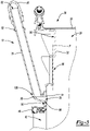
- a water recirculation insert 72 configured to dispense fluid directly into the laundry compartment 70 is mounted to the front ring 32 of the drum housing 28 at a position that is located above the front opening 40 in the front ring 32 (i.e., at the twelve o'clock position when viewed from the front).
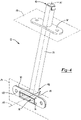
- the water recirculation insert 72 includes a nozzle portion 74 and a tubular portion 76.
- the nozzle portion 74 of the water recirculation insert 72 extends through the front ring 32 to a nozzle opening 78 that is located inside the drum housing cavity 38.
- the nozzle portion 74 also includes an elbow 80 and the tubular portion 76 that extends from the elbow 80 to an inlet end 82 that is configured to be connected to a fluid supply conduit 84 by a coupling 86.
- the fluid supply conduit 84 may be connected to a wash unit pump 88.
- the wash unit pump 88 operates to supply recirculated fluid (i.e., water and/or a water and detergent mix) to the fluid supply conduit 84 and ultimately the water recirculation insert 72.
- the recirculated fluid is then discharged through the nozzle opening 78 of the water recirculation insert 72, where it passes through the drum opening 64 and into the laundry compartment 70.
- the water recirculation insert 72 includes a lower flange 90 and an upper flange 92.
- the front ring 32 includes a front surface 94 that faces the appliance housing 22 and a rear surface 96 that faces the drum 56.
- the front ring 32 extends in a plane P that is perpendicular to the drum housing sidewall 36 and includes a recirculation insert window 98.
- the nozzle portion 74 of the water recirculation insert 72 extends through the recirculation insert window 98 in the front ring 32 of the drum housing 28 and the lower flange 90 abuts the front surface 94 of the front ring 32.
- the lower flange 90 of the water recirculation insert 72 is secured to the front ring 32 of the drum housing 28 using fasteners, as an example.
- the nozzle portion 74 of the water recirculation insert 72 protrudes from the lower flange 90 and at least part of the nozzle portion 74 of the water recirculation insert 72 also protrudes from the rear surface 96 of the front ring 32 into the drum housing cavity 38.
- a recirculation insert opening 99 is provided in the side shroud wall 54.
- the tubular portion 76 of the water recirculation insert 72 extends through the recirculation insert opening 99 in the shroud 50 and the upper flange 92 abuts the side shroud wall 54.
- the upper flange 92 of the water recirculation insert 72 is secured to the side shroud wall 54 using fasteners, as an example.
- the tubular portion 76 of the water recirculation insert 72 extends co-axially about a first axis A1 and linearly from the inlet end 82 to an outlet end 100 opposite the inlet end 82.
- the nozzle portion 74 of the water recirculation insert 72 is connected to the outlet end 100 of the tubular portion 76 at the elbow 80.
- the nozzle portion 74 extends from the elbow 80 to the nozzle opening 78 along a second axis A2 that intersects the first axis A1 at an angle.
- the lower flange 90 of the water recirculation insert 72 extends outwardly from the nozzle portion 74 in a first plane P1 that intersects the nozzle portion 74 of the water recirculation insert 72 at a location between the elbow 80 and the nozzle opening 78.
- the upper flange 92 of the water recirculation insert 72 extends outwardly from the tubular portion 76 in a second plane P2 that intersects the tubular portion 76 of the water recirculation insert 72 at a location between the inlet and outlet ends 82, 100.
- the second plane P2 and thus the upper flange 92 is arranged at an angle relative to the first plane P1 and thus the lower flange 90.
- the lower flange 90 of the recirculation insert may include a flange seal 102 that contacts the front surface 94 of the front ring 32 to form a fluid-tight connection around the recirculation insert window 98 in the front ring 32 of the drum housing 28.
- the water recirculation insert 72 may be made of a wide variety of different materials, in one preferred embodiment, the nozzle portion 74, tubular portion 76, elbow 80, lower flange 90, and upper flange 92 of the water recirculation insert 72 are integrally formed, made of a polymeric material, and the flange seal 102 is made of a co-molded rubber.
- the laundry appliance 20 is a washer and dryer combination appliance that performs both a wash cycle and a drying cycle; however, it should be appreciated that the water recirculation insert 72 described herein may also be used in laundry appliances that only perform a wash cycle (i.e., in washing machines).
Landscapes
- Engineering & Computer Science (AREA)
- Textile Engineering (AREA)
- Detail Structures Of Washing Machines And Dryers (AREA)
- Main Body Construction Of Washing Machines And Laundry Dryers (AREA)
Applications Claiming Priority (1)
| Application Number | Priority Date | Filing Date | Title |
|---|---|---|---|
| US17/338,948 US11788226B2 (en) | 2021-06-04 | 2021-06-04 | Water recirculation insert for laundry appliance |
Publications (1)
| Publication Number | Publication Date |
|---|---|
| EP4098792A1 true EP4098792A1 (fr) | 2022-12-07 |
Family
ID=81850765
Family Applications (1)
| Application Number | Title | Priority Date | Filing Date |
|---|---|---|---|
| EP22175581.2A Withdrawn EP4098792A1 (fr) | 2021-06-04 | 2022-05-25 | Insert de recirculation d'eau pour appareil de blanchisserie |
Country Status (3)
| Country | Link |
|---|---|
| US (1) | US11788226B2 (fr) |
| EP (1) | EP4098792A1 (fr) |
| CN (1) | CN115434123A (fr) |
Citations (5)
| Publication number | Priority date | Publication date | Assignee | Title |
|---|---|---|---|---|
| US4489574A (en) * | 1981-11-10 | 1984-12-25 | The Procter & Gamble Company | Apparatus for highly efficient laundering of textiles |
| WO2009125952A2 (fr) * | 2008-04-08 | 2009-10-15 | Lg Electronics Inc. | Machine à laver |
| CN107938254A (zh) * | 2017-12-28 | 2018-04-20 | Tcl家用电器(合肥)有限公司 | 应用于洗衣机的外桶及洗衣机 |
| WO2019201118A1 (fr) * | 2018-04-16 | 2019-10-24 | 青岛海尔滚筒洗衣机有限公司 | Machine à laver à chargement frontal et son système de pulvérisation |
| EP3613893A1 (fr) * | 2018-08-23 | 2020-02-26 | LG Electronics Inc. -1- | Appareil de traitement du linge |
Family Cites Families (4)
| Publication number | Priority date | Publication date | Assignee | Title |
|---|---|---|---|---|
| US2200144A (en) * | 1938-04-25 | 1940-05-07 | Prosperity Co Inc | Washing machine |
| EP2392720A1 (fr) | 2010-06-04 | 2011-12-07 | Electrolux Home Products Corporation N.V. | Agencement de tube de recirculation d'eau de lavage |
| CN106702685B (zh) | 2015-11-12 | 2019-08-27 | 无锡小天鹅电器有限公司 | 用于滚筒洗衣机的喷淋装置及滚筒洗衣机 |
| CN105332246A (zh) | 2015-11-23 | 2016-02-17 | 惠而浦(中国)股份有限公司 | 一种波轮洗衣机的循环水喷水结构 |
-
2021
- 2021-06-04 US US17/338,948 patent/US11788226B2/en active Active
-
2022
- 2022-05-25 EP EP22175581.2A patent/EP4098792A1/fr not_active Withdrawn
- 2022-06-01 CN CN202210616079.5A patent/CN115434123A/zh active Pending
Patent Citations (5)
| Publication number | Priority date | Publication date | Assignee | Title |
|---|---|---|---|---|
| US4489574A (en) * | 1981-11-10 | 1984-12-25 | The Procter & Gamble Company | Apparatus for highly efficient laundering of textiles |
| WO2009125952A2 (fr) * | 2008-04-08 | 2009-10-15 | Lg Electronics Inc. | Machine à laver |
| CN107938254A (zh) * | 2017-12-28 | 2018-04-20 | Tcl家用电器(合肥)有限公司 | 应用于洗衣机的外桶及洗衣机 |
| WO2019201118A1 (fr) * | 2018-04-16 | 2019-10-24 | 青岛海尔滚筒洗衣机有限公司 | Machine à laver à chargement frontal et son système de pulvérisation |
| EP3613893A1 (fr) * | 2018-08-23 | 2020-02-26 | LG Electronics Inc. -1- | Appareil de traitement du linge |
Also Published As
| Publication number | Publication date |
|---|---|
| US11788226B2 (en) | 2023-10-17 |
| CN115434123A (zh) | 2022-12-06 |
| US20220389641A1 (en) | 2022-12-08 |
Similar Documents
| Publication | Publication Date | Title |
|---|---|---|
| US11035068B2 (en) | Washing machine | |
| JPH03186292A (ja) | 洗濯機 | |
| CN1224749C (zh) | 一种洗衣设备 | |
| CN101280499B (zh) | 滚筒式洗衣机 | |
| CN1616749B (zh) | 滚筒式洗衣机 | |
| JP2010029439A (ja) | 洗濯乾燥機 | |
| CN101698972B (zh) | 滚筒式洗衣机 | |
| JP3560791B2 (ja) | ドラム式洗濯機およびドラム式乾燥洗濯機のドアパッキンの取り付け方法 | |
| CN110552175B (zh) | 一种洗衣机 | |
| EP4098792A1 (fr) | Insert de recirculation d'eau pour appareil de blanchisserie | |
| US12553171B2 (en) | Recirculation hose routing for a laundry appliance | |
| US20120291302A1 (en) | Noise-reducing laundry drum for a household appliance | |
| US11970813B2 (en) | Mating interface assembly between a dispenser hose and wash unit tub of a washer and dryer combination appliance | |
| JPH10263265A (ja) | ドラム式洗濯機 | |
| CN110552166A (zh) | 一种洗衣机的滚筒门体用密封结构及洗衣机 | |
| US12590394B2 (en) | Air bypass seal with backer for improved drying performance in a combination washer/dryer | |
| JP3473574B2 (ja) | 洗濯乾燥機 | |
| KR20060109165A (ko) | 세탁기의 전면부 구조 | |
| JP2004089730A (ja) | ドラム式洗濯機 | |
| CN220450504U (zh) | 洗涤门组件及洗衣机 | |
| JP7335215B2 (ja) | 洗濯乾燥機 | |
| EP4101968B1 (fr) | Boîte de distribution pour appareil combiné lave-linge et sèche-linge | |
| JP7538827B2 (ja) | ドラム式洗濯乾燥機 | |
| CN214655844U (zh) | 一种滚筒洗衣机 | |
| JP2025025043A (ja) | 洗濯機 |
Legal Events
| Date | Code | Title | Description |
|---|---|---|---|
| PUAI | Public reference made under article 153(3) epc to a published international application that has entered the european phase |
Free format text: ORIGINAL CODE: 0009012 |
|
| STAA | Information on the status of an ep patent application or granted ep patent |
Free format text: STATUS: THE APPLICATION HAS BEEN PUBLISHED |
|
| AK | Designated contracting states |
Kind code of ref document: A1 Designated state(s): AL AT BE BG CH CY CZ DE DK EE ES FI FR GB GR HR HU IE IS IT LI LT LU LV MC MK MT NL NO PL PT RO RS SE SI SK SM TR |
|
| RAP3 | Party data changed (applicant data changed or rights of an application transferred) |
Owner name: WHIRLPOOL CORPORATION |
|
| STAA | Information on the status of an ep patent application or granted ep patent |
Free format text: STATUS: THE APPLICATION IS DEEMED TO BE WITHDRAWN |
|
| 18D | Application deemed to be withdrawn |
Effective date: 20230608 |