EP4098818B1 - Construction en porte-à-faux et procédé de fixation - Google Patents
Construction en porte-à-faux et procédé de fixation Download PDFInfo
- Publication number
- EP4098818B1 EP4098818B1 EP21186677.7A EP21186677A EP4098818B1 EP 4098818 B1 EP4098818 B1 EP 4098818B1 EP 21186677 A EP21186677 A EP 21186677A EP 4098818 B1 EP4098818 B1 EP 4098818B1
- Authority
- EP
- European Patent Office
- Prior art keywords
- balcony
- cantilever structure
- attaching
- attached
- actuator
- Prior art date
- Legal status (The legal status is an assumption and is not a legal conclusion. Google has not performed a legal analysis and makes no representation as to the accuracy of the status listed.)
- Active
Links
Images


Classifications
-
- E—FIXED CONSTRUCTIONS
- E04—BUILDING
- E04B—GENERAL BUILDING CONSTRUCTIONS; WALLS, e.g. PARTITIONS; ROOFS; FLOORS; CEILINGS; INSULATION OR OTHER PROTECTION OF BUILDINGS
- E04B1/00—Constructions in general; Structures which are not restricted either to walls, e.g. partitions, or floors or ceilings or roofs
- E04B1/003—Balconies; Decks
-
- B—PERFORMING OPERATIONS; TRANSPORTING
- B25—HAND TOOLS; PORTABLE POWER-DRIVEN TOOLS; MANIPULATORS
- B25B—TOOLS OR BENCH DEVICES NOT OTHERWISE PROVIDED FOR, FOR FASTENING, CONNECTING, DISENGAGING, OR HOLDING
- B25B5/00—Clamps
- B25B5/06—Arrangements for positively actuating jaws
-
- B—PERFORMING OPERATIONS; TRANSPORTING
- B25—HAND TOOLS; PORTABLE POWER-DRIVEN TOOLS; MANIPULATORS
- B25B—TOOLS OR BENCH DEVICES NOT OTHERWISE PROVIDED FOR, FOR FASTENING, CONNECTING, DISENGAGING, OR HOLDING
- B25B5/00—Clamps
- B25B5/06—Arrangements for positively actuating jaws
- B25B5/061—Arrangements for positively actuating jaws with fluid drive
- B25B5/064—Arrangements for positively actuating jaws with fluid drive with clamping means pivoting around an axis perpendicular to the pressing direction
-
- B—PERFORMING OPERATIONS; TRANSPORTING
- B66—HOISTING; LIFTING; HAULING
- B66C—CRANES; LOAD-ENGAGING ELEMENTS OR DEVICES FOR CRANES, CAPSTANS, WINCHES, OR TACKLES
- B66C1/00—Load-engaging elements or devices attached to lifting or lowering gear of cranes or adapted for connection therewith for transmitting lifting forces to articles or groups of articles
- B66C1/10—Load-engaging elements or devices attached to lifting or lowering gear of cranes or adapted for connection therewith for transmitting lifting forces to articles or groups of articles by mechanical means
- B66C1/42—Gripping members engaging only the external or internal surfaces of the articles
- B66C1/425—Gripping members engaging only the external or internal surfaces of the articles motor actuated
-
- B—PERFORMING OPERATIONS; TRANSPORTING
- B66—HOISTING; LIFTING; HAULING
- B66C—CRANES; LOAD-ENGAGING ELEMENTS OR DEVICES FOR CRANES, CAPSTANS, WINCHES, OR TACKLES
- B66C1/00—Load-engaging elements or devices attached to lifting or lowering gear of cranes or adapted for connection therewith for transmitting lifting forces to articles or groups of articles
- B66C1/10—Load-engaging elements or devices attached to lifting or lowering gear of cranes or adapted for connection therewith for transmitting lifting forces to articles or groups of articles by mechanical means
- B66C1/62—Load-engaging elements or devices attached to lifting or lowering gear of cranes or adapted for connection therewith for transmitting lifting forces to articles or groups of articles by mechanical means comprising article-engaging members of a shape complementary to that of the articles to be handled
- B66C1/66—Load-engaging elements or devices attached to lifting or lowering gear of cranes or adapted for connection therewith for transmitting lifting forces to articles or groups of articles by mechanical means comprising article-engaging members of a shape complementary to that of the articles to be handled for engaging holes, recesses, or abutments on articles specially provided for facilitating handling thereof
-
- F—MECHANICAL ENGINEERING; LIGHTING; HEATING; WEAPONS; BLASTING
- F16—ENGINEERING ELEMENTS AND UNITS; GENERAL MEASURES FOR PRODUCING AND MAINTAINING EFFECTIVE FUNCTIONING OF MACHINES OR INSTALLATIONS; THERMAL INSULATION IN GENERAL
- F16B—DEVICES FOR FASTENING OR SECURING CONSTRUCTIONAL ELEMENTS OR MACHINE PARTS TOGETHER, e.g. NAILS, BOLTS, CIRCLIPS, CLAMPS, CLIPS OR WEDGES; JOINTS OR JOINTING
- F16B2/00—Friction-grip releasable fastenings
- F16B2/02—Clamps, i.e. with gripping action effected by positive means other than the inherent resistance to deformation of the material of the fastening
- F16B2/06—Clamps, i.e. with gripping action effected by positive means other than the inherent resistance to deformation of the material of the fastening external, i.e. with contracting action
- F16B2/10—Clamps, i.e. with gripping action effected by positive means other than the inherent resistance to deformation of the material of the fastening external, i.e. with contracting action using pivoting jaws
-
- F—MECHANICAL ENGINEERING; LIGHTING; HEATING; WEAPONS; BLASTING
- F16—ENGINEERING ELEMENTS AND UNITS; GENERAL MEASURES FOR PRODUCING AND MAINTAINING EFFECTIVE FUNCTIONING OF MACHINES OR INSTALLATIONS; THERMAL INSULATION IN GENERAL
- F16B—DEVICES FOR FASTENING OR SECURING CONSTRUCTIONAL ELEMENTS OR MACHINE PARTS TOGETHER, e.g. NAILS, BOLTS, CIRCLIPS, CLAMPS, CLIPS OR WEDGES; JOINTS OR JOINTING
- F16B7/00—Connections of rods or tubes, e.g. of non-circular section, mutually, including resilient connections
- F16B7/22—Connections of rods or tubes, e.g. of non-circular section, mutually, including resilient connections using hooks or like elements
Definitions
- the invention is related to a cantilever structure and its attachment to a building.
- the balcony is one of the most complex building structures. Its attachment to a building must be quick and convenient, and meet strict safety requirements. As a result, the balcony structures, their attachment methods and the devices used for this purpose are constantly being improved.
- the patent document WO2014174269A1 (published 30/10/2014 ) provides for a balcony structure, a method and a tool kit for attaching a balcony to a building or an existing structure.
- One aspect of the invention provides for the balcony for attachment to an existing structure, where the said structure has a plurality of stubs fitted thereto, each stub having a first engagement portion, the balcony having a plurality of second engagement portions on one side of the balcony wherein the first and second engagement portions are arranged to engage with each other so as to cause the weight of the balcony to be supported by the existing structure and the balcony to be securely attached to the structure.
- the fixing includes: a connector section; a clamping section for securing the fixing to the support by clamping at least part of the support between the clamping section and the connector section, the clamping section being adjustably attachable to the connector section by at least one first fastener; a support section for supporting the balcony relative to the support, the support section being adjustably attached to and separated from the connector section by at least one second fastener; and at least one third fastener for securing the balcony to the fixing.
- the invention also provides a balcony and a method of installing the balcony which allow the pitch of the balcony to be adjusted once installed and secured in place, preferably only through access from the underneath of the balcony.
- the closest patent document GB2577113A (published on 18/03/2020 ) provide for the method of installing a balcony to a building facade by aligning the balcony, preferably having a support beam, with a projection of the facade, preferably I-beam stub, such that an activatable tapered shaft or skewer, attached to the balcony, is aligned with the socket in the projection, driving the shaft through the socket to correctly locate and secure the balcony to the facade, then locking the balcony to the facade using further fixings.
- the shaft may be operated by an electric, pneumatic or hydraulic actuator.
- the actuator and the shaft may be removed after the balcony is secured to the projection with the fixings.
- the invention also presents an activatable balcony fixing including a tapered shaft, actuator and mount, as well as a balcony and a kit of parts.
- the present invention differs from the above-mentioned patents in that it provides an alternative method of attaching a balcony by use of a special device.
- the term "balcony” includes various types of balconies as well as other cantilever structures that transmit loads to the building structure, such as marking signs, external photovoltaic structures, heat collectors, accessory holders, arch covers, sun protection systems, plant pots, screens and similar structures that cross the facade of the building and whose load is transferred directly to the structure of the building.
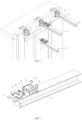
- the method of attaching of the balcony includes the following steps: the balcony is lifted to the required height; the balcony beams are brought to the facade cantilevers using guide plates by aligning the balcony both horizontally and vertically; the balcony beams are attached to the lugs of the fastening cantilever by means of the balcony attaching device, where upon activation of the actuator of the balcony attaching device, which is connected to a scissor mechanism, the latter clamps on the fastening lug; then the balcony beams are fastened to the cantilevers by means of connecting elements.
- the balcony attaching device is mounted on at least two balcony beams.
- the balcony includes load-bearing beams, a frame, a partition/handrail, and finishing materials.
- the balcony attaching device comprises of: a housing; an actuator in the housing; a scissor mechanism connected to the actuator by a sliding element; at least two latches attached to the rear of the housing for securing the housing to a guide plate.
- the scissor mechanism is operated by an electric or hydraulic, or pneumatic actuator and includes: at least a pair of scissors; a central fastening element with at least the pair of scissors; connecting elements, one end of which is connected to the sliding element and the other end - to the scissors.
- the presented method of the balcony attachment by means of the balcony attaching device does not require additional lifting devices for lifting of persons attaching the balcony to the facade. This method also allows for fitting a fully finished balcony structure to a building with minimal resources.
- the balcony attachment method includes the following steps:
- the balcony (4) includes at least load-bearing beams, a frame, a partition/handrail, and finishing materials.
- the balcony (4) is manufactured and assembled at the factory, and delivered to the construction site.
- the balcony (4) is lifted to the required height by a crane or another lifting machine and brought to the facade cantilevers (3) by use of guiding equipment, such as ropes, straps, slings, etc.
- the cantilevers (3) with the fixing lugs (6) attached to them are pre-prepared and attached to the facade on site.
- the balcony attaching device (1) is mounted on at least two balcony beams (2), where before lifting the balcony to the required height, the scissor mechanism (11) of the device (1) is set to its initial position, in which the pair of scissors (16) is opened.
- the actuator (7) of the balcony attaching device (1) connected to the scissor mechanism (11) is activated and the latter is set to its end position in which the pair of scissors ( 16) clamps over the aperture of the fixing lug (6), where the fixing lug (6) is attached to the cantilever (3).
- a safety information equipment (indicator) is activated and informs that the persons attaching the balcony are allowed to climb on the balcony.
- the said safety information mechanism may be a sensor of the shaft motion or a coloured arrow.
- the balcony beam (2) is fastened to the cantilever by fastening elements on a bottom part, where the fastening plates with apertures are provided in the front parts both of the beam (2) and the cantilever (3), and in the upper part, where the apertures are provided on both sides in the front part of the guide plate and on both sides of the upper part of the cantilever. Until the balcony (4) is mechanically fixed to the facade, access to the balcony (4) being attached is prohibited due to safety requirements.
- the balcony attaching device (1) designed for attaching the balcony (4) to a facade comprises ( Fig. 3 ):
- the balcony attaching device (2) is fitted to the balcony beam via the guide plate (5) that is tightly secured to the beam (2)
- the device (1) is fastened to the front part of the guide plate (5) by means of the central fastening element (10), such as a bolt or a pin.
- the device (1) can be fastened to the front part of the guide plate (5) by means of the upper (15) and the lower (14) plates arranged parallel to each other, where both said plates have the fixing apertures at their ends, which coincide with the apertures at the edges of the guide plate (5) ( Fig. 4 ).
- the device (1) is fastened to the rear part of the housing (8) by the notches of the side walls, which are locked in the grooves present on both sides at the end of the guide plate.
- the notches in the side walls of the housing (8) are fixed in the grooves by at least two latches (12) fitted at the rear part of the housing (8).
- the latch (12) Upon pressing the latch (12) in the vertical direction downwards, it presses the pin (13) attached to the housing (8) and the said pin (13) pushes the housing (8) forward until the notches on its side walls are locked in the grooves of the guide plate (5), thereby pushing the scissor mechanism (11) until its central aperture is aligned with the aperture on the fixing plate (5), and in case where the upper (15) and the lower (14) fixing plates are used, the fixing apertures of these plates are aligned with the fixing apertures of the guide plate (5).
- the pin (13) is released and the device (1) can be removed from the guide plate (5) after releasing the central fastening element (10) or the fasteners by which the upper (15) and the lower (14) fixing plates are fixed to the guide plate (5).
- the scissor mechanism (11) comprises ( Fig. 5 ): at least a pair of scissors (16) arranged symmetrically with respect to the vertical axis of a central fastening element (10); the central fastening element (10) with at least the pair of scissors (16); the connecting pieces (17), one end of which is attached to the sliding element (9) and the other end - to the parts of scissors (16).
- a part of scissors (16) is an elongate flat element with one folded end and the apertures for fixing it to the central fastening element (10) and the connecting piece (17) as well as to the other part of scissors.
- the scissor mechanism (11) is operated by an actuator (7) connected through a sliding mechanism (9), one end of which is connected to the actuator (7), the other - to the connecting pieces (17) connected to the parts of scissors (16).
- the said actuator (7) is an electric or hydraulic, or pneumatic actuator.
- the sliding element (9) moves in the longitudinal direction, thus affecting the connecting pieces (17), which change the position of the parts of scissors (16).
- the connecting pieces (17) and the parts of scissors (16) are connected to each other by fasteners.
Landscapes
- Engineering & Computer Science (AREA)
- Mechanical Engineering (AREA)
- Architecture (AREA)
- General Engineering & Computer Science (AREA)
- Physics & Mathematics (AREA)
- Electromagnetism (AREA)
- Civil Engineering (AREA)
- Structural Engineering (AREA)
- Steps, Ramps, And Handrails (AREA)
- Conveying And Assembling Of Building Elements In Situ (AREA)
Claims (9)
- Structure en porte-à-faux (4) comprenant des dispositifs de fixation (1) destinés à être fixés à la façade d'un bâtiment, comprenant :au moins deux poutres (2) sur lesquelles sont fixées des plaques de guidage (5) pour aligner la structure en porte-à-faux (4) horizontalement et verticalement avec les porte-à-faux (3) fixés à la façade ;caractérisée par le fait qu'un dispositif de fixation (1) est fixé de manière amovible sur chacune desdites plaques de guidage (5), ledit dispositif de fixation (1) comprenant :
un boîtier (8), un actionneur (7) enfermé dans le boîtier (8), un mécanisme de ciseaux (11) relié audit actionneur (7) par un élément coulissant (9), où, lors de l'activation de l'actionneur (7), le mécanisme de ciseaux (11) s'accroche à la patte de fixation (6) attachée au porte-à-faux (3) du bâtiment. - Structure en porte-à-faux (4) selon la revendication 1, caractérisée par le fait que ledit dispositif de fixation (1) comprend en outre au moins deux loquets (12) fixés dans la partie arrière du boîtier (8) et destinés à fixer le boîtier (8) à une plaque de guidage (5).
- Structure en porte-à-faux (4) selon n'importe laquelle des revendications précédentes, caractérisée par le fait que l'actionneur (7) est un actionneur électrique, hydraulique ou pneumatique.
- Structure en porte-à-faux (4) selon l'une quelconque des revendications précédentes, caractérisée par le fait que le mécanisme de ciseaux (11) comprend : au moins une paire de ciseaux (16) disposés symétriquement par rapport à l'axe vertical d'un élément de fixation central (10) ; des pièces de liaison (17) dont une extrémité est fixée à l'élément coulissant (9) et l'autre extrémité - aux parties des ciseaux (16).
- Structure en porte-à-faux (4) selon n'importe laquelle des revendications précédentes, caractérisée par le fait que la structure en porte-à-faux (4) est un balcon.
- Structure en porte-à-faux (4) selon la revendication 5, caractérisée par le fait que le balcon comprend un cadre, une cloison/rampe et des matériaux de finition.
- Procédé de fixation d'une structure en porte-à-faux (4) selon l'une des revendications 1 à 6 à un bâtiment, comprenant les étapes suivantes :soulever la structure en porte-à-faux (4) à la hauteur requise ;amener les poutres (2) de la structure en porte-à-faux aux porte-à-faux (3) fixés à la façade du bâtiment grâce aux plaques de guidage (5) fixées aux poutres (2), de manière à ce que la structure en porte-à-faux (4) soit alignée horizontalement et verticalement avec les porte-à-faux (3) ;fixer les poutres (2) aux pattes de fixation (6) fixées aux porte-à-faux (3) grâce au dispositif de fixation (1) ;fixer les poutres (2) de la structure en porte-à-faux aux porte-à-faux (3) au moyen d'éléments de liaison.
- Procédé de fixation selon la revendication 7, caractérisé par le fait que lors de la fixation de la structure en porte-à-faux (4) sur la façade grâce aux dispositifs de fixation de balcon (1), un équipement d'information de sécurité, indicateur, est activé et informe que les personnes fixant les balcons sont autorisés à grimper sur le balcon pour terminer les travaux de fixation.
- Procédé de fixation selon n'importe quelle des revendications 7 et 8 caractérisé par le fait qu'avant de soulever la structure en porte-à-faux (4) à la hauteur requise, le mécanisme à ciseaux (11) du dispositif de fixation de balcon (1) est réglé dans sa position initiale, en laquelle la paire de ciseaux (16) est ouverte.
Priority Applications (1)
| Application Number | Priority Date | Filing Date | Title |
|---|---|---|---|
| EP23190788.2A EP4245712A3 (fr) | 2021-05-31 | 2021-07-20 | Dispositif et procédé de fixation de balcon à une façade |
Applications Claiming Priority (1)
| Application Number | Priority Date | Filing Date | Title |
|---|---|---|---|
| LT2021525A LT6890B (lt) | 2021-05-31 | 2021-05-31 | Balkono tvirtinimo prie fasado įrenginys ir būdas |
Related Child Applications (2)
| Application Number | Title | Priority Date | Filing Date |
|---|---|---|---|
| EP23190788.2A Division EP4245712A3 (fr) | 2021-05-31 | 2021-07-20 | Dispositif et procédé de fixation de balcon à une façade |
| EP23190788.2A Division-Into EP4245712A3 (fr) | 2021-05-31 | 2021-07-20 | Dispositif et procédé de fixation de balcon à une façade |
Publications (3)
| Publication Number | Publication Date |
|---|---|
| EP4098818A1 EP4098818A1 (fr) | 2022-12-07 |
| EP4098818C0 EP4098818C0 (fr) | 2024-04-17 |
| EP4098818B1 true EP4098818B1 (fr) | 2024-04-17 |
Family
ID=76999712
Family Applications (2)
| Application Number | Title | Priority Date | Filing Date |
|---|---|---|---|
| EP21186677.7A Active EP4098818B1 (fr) | 2021-05-31 | 2021-07-20 | Construction en porte-à-faux et procédé de fixation |
| EP23190788.2A Pending EP4245712A3 (fr) | 2021-05-31 | 2021-07-20 | Dispositif et procédé de fixation de balcon à une façade |
Family Applications After (1)
| Application Number | Title | Priority Date | Filing Date |
|---|---|---|---|
| EP23190788.2A Pending EP4245712A3 (fr) | 2021-05-31 | 2021-07-20 | Dispositif et procédé de fixation de balcon à une façade |
Country Status (2)
| Country | Link |
|---|---|
| EP (2) | EP4098818B1 (fr) |
| LT (1) | LT6890B (fr) |
Families Citing this family (4)
| Publication number | Priority date | Publication date | Assignee | Title |
|---|---|---|---|---|
| CN112726814B (zh) * | 2021-01-20 | 2024-04-26 | 江苏建筑职业技术学院 | 一种装配式建筑的外挂可伸缩镂空阳台及其施工方法 |
| SE546038C2 (en) * | 2022-03-03 | 2024-04-23 | Balco Group Ab | System and method for suspending a framework structure on a load bearing structure of a building and use of such suspension system |
| RO137112B1 (ro) * | 2022-07-28 | 2024-08-30 | S&E Innovative Construction | Ansamblu de cuplare rapidă a unui balcon pe structura unei clădiri şi metodă de prindere prin cuplare |
| GB2643366A (en) * | 2023-07-18 | 2026-02-11 | Sapphire Balconies Ltd | Balcony |
Family Cites Families (4)
| Publication number | Priority date | Publication date | Assignee | Title |
|---|---|---|---|---|
| GB2507365B (en) | 2013-04-22 | 2014-10-22 | Sapphire Balustrades Ltd | Balcony |
| GB201507666D0 (en) | 2015-05-05 | 2015-06-17 | Sapphire Balustrades Ltd | Fixing |
| US10150652B2 (en) * | 2017-03-27 | 2018-12-11 | Tei Rock Drills, Inc. | Rod and casing handler |
| GB2577113B (en) | 2018-09-14 | 2020-09-23 | Sapphire Balconies Ltd | Method of installing a balcony, and device for the same |
-
2021
- 2021-05-31 LT LT2021525A patent/LT6890B/lt unknown
- 2021-07-20 EP EP21186677.7A patent/EP4098818B1/fr active Active
- 2021-07-20 EP EP23190788.2A patent/EP4245712A3/fr active Pending
Also Published As
| Publication number | Publication date |
|---|---|
| LT2021525A (fr) | 2022-01-25 |
| EP4245712A3 (fr) | 2023-11-29 |
| LT6890B (lt) | 2022-02-10 |
| EP4098818C0 (fr) | 2024-04-17 |
| EP4245712A2 (fr) | 2023-09-20 |
| EP4098818A1 (fr) | 2022-12-07 |
Similar Documents
| Publication | Publication Date | Title |
|---|---|---|
| EP4098818B1 (fr) | Construction en porte-à-faux et procédé de fixation | |
| US5279389A (en) | Ladder support for flat-roofed building | |
| US11453575B2 (en) | Lifting of building units | |
| US20240044156A1 (en) | Climbing boot for a rail-guided climbing system | |
| CZ2018310A3 (cs) | Skládaná sestava ocelové konstrukce pro zdvihací zařízení | |
| US10676942B2 (en) | Scaffolding apparatus and related methods | |
| KR102327935B1 (ko) | 갱폼추락방지 안전장치 | |
| EP2640908A2 (fr) | Fixation de toit et vérin de levage de toit à raccord rapide | |
| EP4093926B1 (fr) | Élément de liaison de transfert de charge | |
| CN119177762A (zh) | 上拉可调节花篮式墙外悬挑架及其安装方法 | |
| CN219326508U (zh) | 一种起重机梁体吊装索具支撑装置 | |
| US5492201A (en) | Method and apparatus for installing and balancing an elevator car | |
| CN210976550U (zh) | 一种可调节紧固工具式外挂防护架体系 | |
| CN211114730U (zh) | 一种采光顶安装用操作平台 | |
| CN216239651U (zh) | 一种建筑施工脚手架 | |
| CN217808268U (zh) | 一种木结构集成建筑多功能吊具 | |
| WO2025226855A1 (fr) | Appareil d'abri pour bâtiments modulaires | |
| CN116927352B (en) | Integrated installation device of assembled enclosure wallboard and roof beam | |
| CN212101606U (zh) | 单元式幕墙安装吊具 | |
| CN210823440U (zh) | 一种油箱安全吊索架 | |
| JPH0736001Y2 (ja) | 着脱式揚重装置 | |
| JPH0330390Y2 (fr) | ||
| JP2559503Y2 (ja) | パネルの吊具 | |
| KR20110003469U (ko) | 거치용 브라켓 구조 | |
| DK202001471A1 (en) | A safety device |
Legal Events
| Date | Code | Title | Description |
|---|---|---|---|
| PUAI | Public reference made under article 153(3) epc to a published international application that has entered the european phase |
Free format text: ORIGINAL CODE: 0009012 |
|
| STAA | Information on the status of an ep patent application or granted ep patent |
Free format text: STATUS: THE APPLICATION HAS BEEN PUBLISHED |
|
| AK | Designated contracting states |
Kind code of ref document: A1 Designated state(s): AL AT BE BG CH CY CZ DE DK EE ES FI FR GB GR HR HU IE IS IT LI LT LU LV MC MK MT NL NO PL PT RO RS SE SI SK SM TR |
|
| STAA | Information on the status of an ep patent application or granted ep patent |
Free format text: STATUS: REQUEST FOR EXAMINATION WAS MADE |
|
| P01 | Opt-out of the competence of the unified patent court (upc) registered |
Effective date: 20230526 |
|
| 17P | Request for examination filed |
Effective date: 20230627 |
|
| RBV | Designated contracting states (corrected) |
Designated state(s): AL AT BE BG CH CY CZ DE DK EE ES FI FR GB GR HR HU IE IS IT LI LT LU LV MC MK MT NL NO PL PT RO RS SE SI SK SM TR |
|
| RIN1 | Information on inventor provided before grant (corrected) |
Inventor name: MASICKAS, TADAS Inventor name: GUDAITIS, VAIDAS Inventor name: RADKEVICIUS, KAROLIS |
|
| GRAP | Despatch of communication of intention to grant a patent |
Free format text: ORIGINAL CODE: EPIDOSNIGR1 |
|
| STAA | Information on the status of an ep patent application or granted ep patent |
Free format text: STATUS: GRANT OF PATENT IS INTENDED |
|
| RIC1 | Information provided on ipc code assigned before grant |
Ipc: F16B 7/22 20060101ALN20231019BHEP Ipc: B66C 1/66 20060101ALI20231019BHEP Ipc: B66C 1/42 20060101ALI20231019BHEP Ipc: B25B 5/06 20060101ALI20231019BHEP Ipc: F16B 2/10 20060101ALI20231019BHEP Ipc: E04B 1/00 20060101AFI20231019BHEP |
|
| RIC1 | Information provided on ipc code assigned before grant |
Ipc: F16B 7/22 20060101ALN20231024BHEP Ipc: B66C 1/66 20060101ALI20231024BHEP Ipc: B66C 1/42 20060101ALI20231024BHEP Ipc: B25B 5/06 20060101ALI20231024BHEP Ipc: F16B 2/10 20060101ALI20231024BHEP Ipc: E04B 1/00 20060101AFI20231024BHEP |
|
| INTG | Intention to grant announced |
Effective date: 20231108 |
|
| GRAS | Grant fee paid |
Free format text: ORIGINAL CODE: EPIDOSNIGR3 |
|
| GRAA | (expected) grant |
Free format text: ORIGINAL CODE: 0009210 |
|
| STAA | Information on the status of an ep patent application or granted ep patent |
Free format text: STATUS: THE PATENT HAS BEEN GRANTED |
|
| AK | Designated contracting states |
Kind code of ref document: B1 Designated state(s): AL AT BE BG CH CY CZ DE DK EE ES FI FR GB GR HR HU IE IS IT LI LT LU LV MC MK MT NL NO PL PT RO RS SE SI SK SM TR |
|
| REG | Reference to a national code |
Ref country code: GB Ref legal event code: FG4D |
|
| REG | Reference to a national code |
Ref country code: CH Ref legal event code: EP |
|
| REG | Reference to a national code |
Ref country code: IE Ref legal event code: FG4D Ref country code: DE Ref legal event code: R096 Ref document number: 602021011836 Country of ref document: DE |
|
| U01 | Request for unitary effect filed |
Effective date: 20240510 |
|
| U07 | Unitary effect registered |
Designated state(s): AT BE BG DE DK EE FI FR IT LT LU LV MT NL PT SE SI Effective date: 20240522 |
|
| P04 | Withdrawal of opt-out of the competence of the unified patent court (upc) registered |
Effective date: 20240517 |
|
| U20 | Renewal fee for the european patent with unitary effect paid |
Year of fee payment: 4 Effective date: 20240704 |
|
| PG25 | Lapsed in a contracting state [announced via postgrant information from national office to epo] |
Ref country code: IS Free format text: LAPSE BECAUSE OF FAILURE TO SUBMIT A TRANSLATION OF THE DESCRIPTION OR TO PAY THE FEE WITHIN THE PRESCRIBED TIME-LIMIT Effective date: 20240817 |
|
| PG25 | Lapsed in a contracting state [announced via postgrant information from national office to epo] |
Ref country code: HR Free format text: LAPSE BECAUSE OF FAILURE TO SUBMIT A TRANSLATION OF THE DESCRIPTION OR TO PAY THE FEE WITHIN THE PRESCRIBED TIME-LIMIT Effective date: 20240417 |
|
| PG25 | Lapsed in a contracting state [announced via postgrant information from national office to epo] |
Ref country code: GR Free format text: LAPSE BECAUSE OF FAILURE TO SUBMIT A TRANSLATION OF THE DESCRIPTION OR TO PAY THE FEE WITHIN THE PRESCRIBED TIME-LIMIT Effective date: 20240718 |
|
| PG25 | Lapsed in a contracting state [announced via postgrant information from national office to epo] |
Ref country code: ES Free format text: LAPSE BECAUSE OF FAILURE TO SUBMIT A TRANSLATION OF THE DESCRIPTION OR TO PAY THE FEE WITHIN THE PRESCRIBED TIME-LIMIT Effective date: 20240417 |
|
| PG25 | Lapsed in a contracting state [announced via postgrant information from national office to epo] |
Ref country code: PL Free format text: LAPSE BECAUSE OF FAILURE TO SUBMIT A TRANSLATION OF THE DESCRIPTION OR TO PAY THE FEE WITHIN THE PRESCRIBED TIME-LIMIT Effective date: 20240417 |
|
| PG25 | Lapsed in a contracting state [announced via postgrant information from national office to epo] |
Ref country code: PL Free format text: LAPSE BECAUSE OF FAILURE TO SUBMIT A TRANSLATION OF THE DESCRIPTION OR TO PAY THE FEE WITHIN THE PRESCRIBED TIME-LIMIT Effective date: 20240417 Ref country code: IS Free format text: LAPSE BECAUSE OF FAILURE TO SUBMIT A TRANSLATION OF THE DESCRIPTION OR TO PAY THE FEE WITHIN THE PRESCRIBED TIME-LIMIT Effective date: 20240817 Ref country code: HR Free format text: LAPSE BECAUSE OF FAILURE TO SUBMIT A TRANSLATION OF THE DESCRIPTION OR TO PAY THE FEE WITHIN THE PRESCRIBED TIME-LIMIT Effective date: 20240417 Ref country code: GR Free format text: LAPSE BECAUSE OF FAILURE TO SUBMIT A TRANSLATION OF THE DESCRIPTION OR TO PAY THE FEE WITHIN THE PRESCRIBED TIME-LIMIT Effective date: 20240718 Ref country code: ES Free format text: LAPSE BECAUSE OF FAILURE TO SUBMIT A TRANSLATION OF THE DESCRIPTION OR TO PAY THE FEE WITHIN THE PRESCRIBED TIME-LIMIT Effective date: 20240417 Ref country code: RS Free format text: LAPSE BECAUSE OF FAILURE TO SUBMIT A TRANSLATION OF THE DESCRIPTION OR TO PAY THE FEE WITHIN THE PRESCRIBED TIME-LIMIT Effective date: 20240717 |
|
| P05 | Withdrawal of opt-out of the competence of the unified patent court (upc) changed |
Free format text: CASE NUMBER: APP_28202/2024 Effective date: 20240522 |
|
| REG | Reference to a national code |
Ref country code: DE Ref legal event code: R097 Ref document number: 602021011836 Country of ref document: DE |
|
| PG25 | Lapsed in a contracting state [announced via postgrant information from national office to epo] |
Ref country code: CZ Free format text: LAPSE BECAUSE OF FAILURE TO SUBMIT A TRANSLATION OF THE DESCRIPTION OR TO PAY THE FEE WITHIN THE PRESCRIBED TIME-LIMIT Effective date: 20240417 |
|
| PG25 | Lapsed in a contracting state [announced via postgrant information from national office to epo] |
Ref country code: RO Free format text: LAPSE BECAUSE OF FAILURE TO SUBMIT A TRANSLATION OF THE DESCRIPTION OR TO PAY THE FEE WITHIN THE PRESCRIBED TIME-LIMIT Effective date: 20240417 Ref country code: SK Free format text: LAPSE BECAUSE OF FAILURE TO SUBMIT A TRANSLATION OF THE DESCRIPTION OR TO PAY THE FEE WITHIN THE PRESCRIBED TIME-LIMIT Effective date: 20240417 |
|
| PG25 | Lapsed in a contracting state [announced via postgrant information from national office to epo] |
Ref country code: SM Free format text: LAPSE BECAUSE OF FAILURE TO SUBMIT A TRANSLATION OF THE DESCRIPTION OR TO PAY THE FEE WITHIN THE PRESCRIBED TIME-LIMIT Effective date: 20240417 |
|
| PG25 | Lapsed in a contracting state [announced via postgrant information from national office to epo] |
Ref country code: SM Free format text: LAPSE BECAUSE OF FAILURE TO SUBMIT A TRANSLATION OF THE DESCRIPTION OR TO PAY THE FEE WITHIN THE PRESCRIBED TIME-LIMIT Effective date: 20240417 Ref country code: SK Free format text: LAPSE BECAUSE OF FAILURE TO SUBMIT A TRANSLATION OF THE DESCRIPTION OR TO PAY THE FEE WITHIN THE PRESCRIBED TIME-LIMIT Effective date: 20240417 Ref country code: RO Free format text: LAPSE BECAUSE OF FAILURE TO SUBMIT A TRANSLATION OF THE DESCRIPTION OR TO PAY THE FEE WITHIN THE PRESCRIBED TIME-LIMIT Effective date: 20240417 Ref country code: CZ Free format text: LAPSE BECAUSE OF FAILURE TO SUBMIT A TRANSLATION OF THE DESCRIPTION OR TO PAY THE FEE WITHIN THE PRESCRIBED TIME-LIMIT Effective date: 20240417 |
|
| PG25 | Lapsed in a contracting state [announced via postgrant information from national office to epo] |
Ref country code: MC Free format text: LAPSE BECAUSE OF FAILURE TO SUBMIT A TRANSLATION OF THE DESCRIPTION OR TO PAY THE FEE WITHIN THE PRESCRIBED TIME-LIMIT Effective date: 20240417 |
|
| PLBE | No opposition filed within time limit |
Free format text: ORIGINAL CODE: 0009261 |
|
| STAA | Information on the status of an ep patent application or granted ep patent |
Free format text: STATUS: NO OPPOSITION FILED WITHIN TIME LIMIT |
|
| 26N | No opposition filed |
Effective date: 20250120 |
|
| U20 | Renewal fee for the european patent with unitary effect paid |
Year of fee payment: 5 Effective date: 20250527 |
|
| PGFP | Annual fee paid to national office [announced via postgrant information from national office to epo] |
Ref country code: GB Payment date: 20250527 Year of fee payment: 5 |
|
| PGFP | Annual fee paid to national office [announced via postgrant information from national office to epo] |
Ref country code: NO Payment date: 20250528 Year of fee payment: 5 |
|
| PGFP | Annual fee paid to national office [announced via postgrant information from national office to epo] |
Ref country code: IE Payment date: 20250527 Year of fee payment: 5 |
|
| PGFP | Annual fee paid to national office [announced via postgrant information from national office to epo] |
Ref country code: CH Payment date: 20250801 Year of fee payment: 5 |
|
| PG25 | Lapsed in a contracting state [announced via postgrant information from national office to epo] |
Ref country code: CY Free format text: LAPSE BECAUSE OF FAILURE TO SUBMIT A TRANSLATION OF THE DESCRIPTION OR TO PAY THE FEE WITHIN THE PRESCRIBED TIME-LIMIT; INVALID AB INITIO Effective date: 20210720 |
|
| PG25 | Lapsed in a contracting state [announced via postgrant information from national office to epo] |
Ref country code: HU Free format text: LAPSE BECAUSE OF FAILURE TO SUBMIT A TRANSLATION OF THE DESCRIPTION OR TO PAY THE FEE WITHIN THE PRESCRIBED TIME-LIMIT; INVALID AB INITIO Effective date: 20210720 |