EP4098832B1 - Module destiné à être agencé sur une face charnière d'un battant de fenêtre ou de porte - Google Patents
Module destiné à être agencé sur une face charnière d'un battant de fenêtre ou de porte Download PDFInfo
- Publication number
- EP4098832B1 EP4098832B1 EP21177455.9A EP21177455A EP4098832B1 EP 4098832 B1 EP4098832 B1 EP 4098832B1 EP 21177455 A EP21177455 A EP 21177455A EP 4098832 B1 EP4098832 B1 EP 4098832B1
- Authority
- EP
- European Patent Office
- Prior art keywords
- assembly
- securing portion
- securing
- fitting part
- section
- Prior art date
- Legal status (The legal status is an assumption and is not a legal conclusion. Google has not performed a legal analysis and makes no representation as to the accuracy of the status listed.)
- Active
Links
Images


Classifications
-
- E—FIXED CONSTRUCTIONS
- E05—LOCKS; KEYS; WINDOW OR DOOR FITTINGS; SAFES
- E05D—HINGES OR SUSPENSION DEVICES FOR DOORS, WINDOWS OR WINGS
- E05D7/00—Hinges or pivots of special construction
- E05D7/0009—Adjustable hinges
- E05D7/0018—Adjustable hinges at the hinge axis
- E05D7/0027—Adjustable hinges at the hinge axis in an axial direction
-
- E—FIXED CONSTRUCTIONS
- E05—LOCKS; KEYS; WINDOW OR DOOR FITTINGS; SAFES
- E05D—HINGES OR SUSPENSION DEVICES FOR DOORS, WINDOWS OR WINGS
- E05D15/00—Suspension arrangements for wings
- E05D15/48—Suspension arrangements for wings allowing alternative movements
- E05D15/52—Suspension arrangements for wings allowing alternative movements for opening about a vertical as well as a horizontal axis
- E05D15/5214—Corner supports
-
- E—FIXED CONSTRUCTIONS
- E05—LOCKS; KEYS; WINDOW OR DOOR FITTINGS; SAFES
- E05D—HINGES OR SUSPENSION DEVICES FOR DOORS, WINDOWS OR WINGS
- E05D5/00—Construction of single parts, e.g. the parts for attachment
- E05D5/10—Pins, sockets or sleeves; Removable pins
- E05D5/14—Construction of sockets or sleeves
-
- E—FIXED CONSTRUCTIONS
- E05—LOCKS; KEYS; WINDOW OR DOOR FITTINGS; SAFES
- E05D—HINGES OR SUSPENSION DEVICES FOR DOORS, WINDOWS OR WINGS
- E05D7/00—Hinges or pivots of special construction
- E05D7/0009—Adjustable hinges
- E05D7/0018—Adjustable hinges at the hinge axis
- E05D7/0027—Adjustable hinges at the hinge axis in an axial direction
- E05D2007/0036—Adjustable hinges at the hinge axis in an axial direction with axially fixed hinge pins
-
- E—FIXED CONSTRUCTIONS
- E05—LOCKS; KEYS; WINDOW OR DOOR FITTINGS; SAFES
- E05Y—INDEXING SCHEME ASSOCIATED WITH SUBCLASSES E05D AND E05F, RELATING TO CONSTRUCTION ELEMENTS, ELECTRIC CONTROL, POWER SUPPLY, POWER SIGNAL OR TRANSMISSION, USER INTERFACES, MOUNTING OR COUPLING, DETAILS, ACCESSORIES, AUXILIARY OPERATIONS NOT OTHERWISE PROVIDED FOR, APPLICATION THEREOF
- E05Y2600/00—Mounting or coupling arrangements for elements provided for in this subclass
- E05Y2600/50—Mounting methods; Positioning
- E05Y2600/56—Positioning, e.g. re-positioning, or pre-mounting
-
- E—FIXED CONSTRUCTIONS
- E05—LOCKS; KEYS; WINDOW OR DOOR FITTINGS; SAFES
- E05Y—INDEXING SCHEME ASSOCIATED WITH SUBCLASSES E05D AND E05F, RELATING TO CONSTRUCTION ELEMENTS, ELECTRIC CONTROL, POWER SUPPLY, POWER SIGNAL OR TRANSMISSION, USER INTERFACES, MOUNTING OR COUPLING, DETAILS, ACCESSORIES, AUXILIARY OPERATIONS NOT OTHERWISE PROVIDED FOR, APPLICATION THEREOF
- E05Y2800/00—Details, accessories and auxiliary operations not otherwise provided for
- E05Y2800/20—Combinations of elements
-
- E—FIXED CONSTRUCTIONS
- E05—LOCKS; KEYS; WINDOW OR DOOR FITTINGS; SAFES
- E05Y—INDEXING SCHEME ASSOCIATED WITH SUBCLASSES E05D AND E05F, RELATING TO CONSTRUCTION ELEMENTS, ELECTRIC CONTROL, POWER SUPPLY, POWER SIGNAL OR TRANSMISSION, USER INTERFACES, MOUNTING OR COUPLING, DETAILS, ACCESSORIES, AUXILIARY OPERATIONS NOT OTHERWISE PROVIDED FOR, APPLICATION THEREOF
- E05Y2800/00—Details, accessories and auxiliary operations not otherwise provided for
- E05Y2800/67—Materials; Strength alteration thereof
- E05Y2800/684—Strength alteration by weakening, e.g. by applying grooves
-
- E—FIXED CONSTRUCTIONS
- E05—LOCKS; KEYS; WINDOW OR DOOR FITTINGS; SAFES
- E05Y—INDEXING SCHEME ASSOCIATED WITH SUBCLASSES E05D AND E05F, RELATING TO CONSTRUCTION ELEMENTS, ELECTRIC CONTROL, POWER SUPPLY, POWER SIGNAL OR TRANSMISSION, USER INTERFACES, MOUNTING OR COUPLING, DETAILS, ACCESSORIES, AUXILIARY OPERATIONS NOT OTHERWISE PROVIDED FOR, APPLICATION THEREOF
- E05Y2900/00—Application of doors, windows, wings or fittings thereof
- E05Y2900/10—Application of doors, windows, wings or fittings thereof for buildings or parts thereof
- E05Y2900/13—Type of wing
- E05Y2900/148—Windows
Definitions
- the invention relates to an assembly for arrangement on a hinge side of a sash of a window or a door, with a fitting part for attachment to the sash, the fitting part having a receiving space for rotatably receiving at least the front end of a frame of the window or door or having arranged bearing bolt and wherein the fitting part is provided with an adjustment screw movable along an adjustment axis for adjusting a position of the fitting part relative to the bearing bolt.
- Assemblies of the aforementioned type are also known as "corner bearings". They are used to rotate the sash of a window or door about an axis of rotation relative to a fixed frame. In order to enable the sash to be adjusted in height relative to the frame, an adjusting screw is provided which is screwed to the fitting part and can assume different positions along an adjusting axis.
- the assembly according to the invention makes it possible to dispense with a bearing sleeve known from the prior art.
- the assembly according to the invention allows a simple and quick assembly of a sash on a frame and a simple and quick adjustment of the height of the sash and also a reliable safeguard against unwanted adjustment of the height of the sash.
- the weight of the wing is introduced via the fitting into the adjusting screw and from there into the intermediate section.
- the weight of components mentioned above is supported on the frame-side bearing bolt.
- the intermediate section is connected to a securing section, so that the securing section can initially be handled together with the intermediate section when the assembly is assembled.
- the securing section In an assembled state, the securing section is separated from the intermediate section and engages in an external thread of the adjusting screw and is at the same time secured against rotation on the fitting part.
- the engagement of the external thread of the adjusting screw in the securing section, starting from a pre-assembly state of the additional part, is preferably accompanied by the adjusting screw cutting or stamping an internal thread with its external thread into a surface section of the securing section.
- the securing section has the effect that although the adjusting screw can still be rotated relative to the fitting part, the anti-rotation effect of the securing section must be overcome for this purpose.
- the adjusting screw After detachment of the securing portion from the intermediate portion, the adjusting screw is movable together with the intermediate portion relative to the fitting along the adjustment axis independently of the securing portion (separated in this state).
- a transition from the pre-assembly state to the assembly state is accompanied by the front end of the adjusting screw coming into contact with a contact surface of the intermediate section when the adjusting screw is screwed into an internal thread of the fitting part, and further screwing in the adjusting screw is associated with this that a compressive force is exerted from the front end of the adjusting screw onto the abutment surface, whereby the intermediate section is separated from the securing section.
- the adjusting screw is thus initially screwed with its external thread to an internal thread of the fitting part, with the external thread of the adjusting screw also coming into engagement with a surface of the securing section which faces the adjusting screw.
- the intermediate section and the securing section are connected to one another in a materially bonded manner. This enables the inexpensive provision of an easy-to-handle additional part.
- a connection area between the intermediate section and the securing section is designed as a predetermined breaking point.
- a predetermined breaking point is understood to mean a material section that is smaller than a cross section of the securing section oriented perpendicularly to the adjustment axis in an area adjacent to the predetermined breaking point and than a cross section of the intermediate section oriented perpendicularly to the adjustment axis in an area adjacent to the predetermined breaking point.
- the additional part is made from a plastic material, in particular as an injection molded part.
- This material is inexpensive, has an anti-twist effect and can be easily deformed by screwing in the adjusting screw.
- the securing section is preferably designed in the form of a web and thus requires only little installation space, but can engage with the external thread of the adjusting screw via a large number of thread turns.
- the securing section extends parallel to the adjustment axis in the assembly position and/or if the securing section is inclined relative to the adjustment axis in the pre-assembly position.
- An arrangement that is parallel to the adjustment axis in the assembly position enables a space-saving design and a uniform securing effect over a number of thread turns of the adjustment screw.
- Inclining the securing section in the pre-assembly position enables a funnel to be formed, into which the front end of the adjusting screw can be inserted. This simplifies the first impression of the external thread of the adjusting screw in a surface of the securing section facing the adjusting screw.
- a groove is provided on the fitting part to prevent the securing section from rotating relative to the fitting part, in which groove the securing section is arranged.
- This groove is made, for example, by machining the fitting part.
- the groove preferably extends parallel to the adjustment axis.
- the intermediate section prefferably has an anti-twist section which interacts with the fitting part. This has the advantage that during use of the wing and its rotation relative to a frame, the intermediate section is fixed in the direction of rotation relative to the wing, so that frictional movement between the front end of the adjusting screw and the contact surface of the intermediate section is prevented. In this way it is ensured that when the sash rotates relative to the frame, a frictional movement takes place exclusively between surfaces of the intermediate section and the bearing pin.
- the anti-twist section of the intermediate section is preferably also mounted in the groove, which also serves to arrange the securing section.
- the groove can have the same cross section over its entire extension and in particular both at the level of the securing section and at the level of the anti-twist section of the intermediate section.
- the additional part has a bearing surface for resting on the front end of the bearing bolt and if the bearing surface has a concave curvature. This enables the provision of a centering effect of the intermediate section relative to the bearing pin and also a friction-optimized contact between the bearing pin and the bearing surface.
- the bearing bolt preferably also has a curved surface at its front end, which is curved in a complementary manner to the curvature of the bearing surface, ie in particular in a convex manner.
- the radius of curvature of the surface of the bearing pin can be identical to the radius of curvature of the curvature of the bearing surface or slightly smaller.
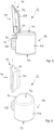
- An embodiment of an assembly 10 is denoted overall by the reference numeral 10 in the drawing.
- the assembly 10 comprises a fitting part 12 which is connected or will be connected to a sash of a window or door by a portion which is known per se and is therefore not shown.
- the assembly 10 is used to rotate the wing together with the fitting part 12 to a bearing pin 14 which is arranged on a frame of the window or door.
- the bearing pin 14 can be a component that is in a fixed position (for a wing that can only be rotated) or a component that can itself be tilted, so that the wing can be rotated not only around the bearing pin 14, but together with the bearing pin 14 can also be brought into a tilted position.
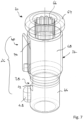
- the fitting part 12 comprises an approximately hollow-cylindrical receiving section 16 which peripherally delimits a receiving space 18 which serves, among other things, for rotatably receiving at least one front end 20 of the bearing pin 14 .
- the receiving space 18 is open at a lower end 22 in the installed position of the assembly 10, for the purpose of passage or entry of the bearing pin 14.
- the receiving space 18 is also open at an upper end 24 in the installed position of the assembly 10, which makes it possible that a Additional part 26 is introduced into the receiving space 18 from the upper end 24 .
- the receiving space 18 has an internal thread 28 along its extension between the lower end 22 and the upper end 24 at least along a partial section, which is used for screwing with an adjusting screw 30 which has an external thread 32 .
- a groove 34 is also provided on the peripheral boundary of the receiving space 18 , which widens the otherwise cylindrical receiving space 18 in the area of the groove 34 .
- the groove 34 extends from the upper end 24 of the receiving space 18 to a shoulder 36 which is provided above the lower end 22.
- the additional part 26 is in Figures 5 and 6 shown on its own, in a pre-assembly state (cf. figure 5 ) and in an assembled state (cf. figure 6 ).
- the additional part 26 comprises an intermediate section 38, which is embodied, for example, approximately cylindrically, and a web-shaped securing section 40.
- the intermediate section 38 extends between an upper bearing surface 42 in the installed position, which extends, for example, in a straight plane, and a lower bearing surface 44 in the installed position, cf. figures 1 and 8th .
- the intermediate section 38 has a cylindrical main body 46 protruding Anti-rotation section 48, which secures the intermediate section 38 against rotation within the receiving space 18, while allowing a displacement of the intermediate section 38 within the receiving space 18 parallel to an adjustment axis 50.
- the securing section 40 is web-shaped and extends in the preassembled state of the additional part 26 between a connection area 52 for connection to the intermediate section 38 and a free end 54 facing away therefrom, which is preferably provided with an insertion bevel 56 .
- the insertion bevel 56 serves to support the insertion of a front end 58 of the adjusting screw 30, cf. figure 8 .
- the securing section 40 is web-shaped and extends along an axis 60 which is inclined relative to the adjustment axis 50 when the additional part 26 is in a preassembled state, cf. figure 1 , and runs parallel to the adjustment axis 50 in an assembled state, cf. figure 8 .
- the additional part 26 is made in particular from a plastic material.
- the connection area 52 has a predetermined breaking point 62 which has a small, locally limited cross-section compared to the cross-section of the securing section 40 and compared to the cross-section of the main body 46 of the intermediate section 38 .
- the adjusting screw 30 has a screw head 64 with a tool engagement section 66 at its end remote from the front end 58 . This is followed in the direction of the front end 58 by a shaft 68 which carries the external thread 32 .
- the bearing bolt 14 of a frame of a window or a door or also a bearing bolt 14 of an assembly device is arranged with its front end 20 inside the receiving space 18 .
- a bottom 68, cf. figure 1 the fitting part 12 rests on a mounting surface 70 indicated schematically.
- the additional part 26 is introduced into the receiving space 18 from the upper end 24 .
- the additional part 26 then comes into contact (due to gravity) with its bearing surface 44 with the front end 20 of the bearing pin 14.
- the adjusting screw 30 is then inserted with the front end 58 forward from the upper end 24 into the receiving space 18, this insertion being supported by the inclined surface 56 of the securing section 40 and by the initially inclined position of the securing section 40 along the axis 60.
- the end of the external thread 32 adjacent to the front end 58 comes into engagement with an upper end of the internal thread 28 of the receiving space 18.
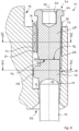
- the external thread 32 also comes into engagement with a surface 68 of the securing section 40 facing the receiving space 18, cf figures 1 and 5 . Due to this intervention, the (harder) external thread 32 of the adjusting screw deforms the (softer) securing section 40, so that a deformed section 70 (cf. figures 6 and 9 ) arises, which has an internal thread complementary to the external thread 32 and is in an anti-rotational engagement with the external thread 32 of the adjusting screw 30 .
- the adjusting screw 30 not only engages with its external thread 32 with the surface 68 of the securing section 40 (which is initially still connected to the intermediate section 38), but also with its end face during the course of screwing with the fitting part 12 End 58 in contact with the abutment surface 52 of the intermediate portion 38.
- the adjusting screw 30 can only be further screwed into the receiving space 18 when the intermediate portion 38 is released from the securing portion 40, which is made possible by the fact that the Predetermined breaking point 62, caused by the pressure of the adjusting screw 30, gives way and the securing section 40, starting from the inclined pre-assembly position (cf. figure 1 ) in a position parallel to the adjustment axis 50 (cf. figure 8 ) is transferred.
- the intermediate section 38 can move together with the adjustment screw 30 along the adjustment axis 50, so that a height of the Fitting part 12 can be adjusted relative to the front end 20 of the bearing pin 14.
- the securing section 40 is in continuous, anti-rotational engagement with the external thread 32 of the adjusting screw 30.
- the securing section is fixed in the groove 34 of the fitting part 12, viewed parallel to the adjustment axis 50.
- the adjustment screw 30 is arranged on the fitting part 12 in a non-rotating manner once the adjustment process is complete, so that an unwanted adjustment of the position of the adjustment screw 30 relative to the fitting part 12 and thus an unwanted adjustment of the Height of the wing is prevented.
- the main body 46 preferably has a material recess 72 below the connection area 52/the predetermined breaking point 62, which is dimensioned in such a way that the securing section 40 can also be attached to the upper end of the main body 46 of the Intermediate section 38 can be arranged past and adjacent to the anti-rotation section 48, compare e.g. 1 and 8th .
- the subassembly 10 is either fully assembled together with a wing on a frame-side bearing pin 14 or, in the event that the bearing pin 14 can be removed from an assembly device provided to be lifted from this bearing pin.
- the intermediate section 38 it is possible for the intermediate section 38 to be arranged in a loosely movable manner within the receiving space 18 between the stop 36 and the front end 58 of the adjusting screw 30 .
- this mobility is canceled again when the assembly 10 is mounted on a bearing pin 14 fixed to the frame; In the assembly position on a bearing bolt 14, the weight of a wing is supported via the fitting part 12, the adjusting screw 30 and the intermediate section 38 on the front end 20 of a bearing bolt 14.
Landscapes
- Engineering & Computer Science (AREA)
- Mechanical Engineering (AREA)
- Hinges (AREA)
Claims (9)
- Module (10) destiné à être agencé au niveau d'un côté charnière d'un battant de fenêtre ou de porte, comprenant une ferrure (12) destinée à être fixée au battant, dans lequel la ferrure présente un espace de réception (18) destiné à recevoir de manière rotative au moins l'extrémité frontale (20) d'un boulon de palier (14) agencé ou pouvant être agencé au niveau d'un cadre de la fenêtre ou de la porte, et dans lequel la ferrure (12) est munie d'une vis de réglage (30) pouvant être déplacée le long d'un axe de réglage (50) afin de régler une position de la ferrure (12) par rapport au boulon de palier (14), comprenant une pièce supplémentaire (26) présentant une section intermédiaire (38) et une section de blocage (40), dans lequel la section intermédiaire (38) est conçue pour être agencée entre une extrémité frontale (58) de la vis de réglage (30) et l'extrémité frontale (20) du boulon de palier (14), dans lequel la section de blocage (40) est bloquée en rotation au niveau de la ferrure (12), dans lequel, dans un état de pré-assemblage de la pièce supplémentaire (26), la section intermédiaire (38) et la section de blocage (40) sont reliées l'une à l'autre et dans lequel, dans un état d'assemblage de la pièce supplémentaire (26), la section intermédiaire (38) est séparée de la section de blocage (40) et peut être déplacée conjointement avec la vis de réglage (30) le long de l'axe de réglage (50), dans lequel, dans l'état de pré-assemblage de la pièce supplémentaire (26), la section intermédiaire (38) et la section de blocage (40) sont reliées l'une à l'autre par complémentarité de matière et une région de liaison (52) entre la section intermédiaire (38) et la section de blocage (40) est conçue comme un point de rupture intentionnellement prévu (62), caractérisé en ce que la section de blocage (40) est conçue pour venir en prise dans un filetage extérieur (32) de la vis de réglage (30).
- Module (10) selon la revendication 1, caractérisé en ce que le passage de l'état de pré-assemblage à l'état d'assemblage implique que l'extrémité frontale (58) de la vis de réglage (30) vienne en contact avec une surface de contact (42) de la partie intermédiaire (38) lors du vissage de la vis de réglage (30) dans un filetage intérieur (28) de la ferrure (12), et en ce qu'un autre vissage de la vis de réglage (30) implique l'exercice d'une force de pression de l'extrémité frontale (58) de la vis de réglage (30) sur la surface de contact (42), de sorte que la partie intermédiaire (38) est séparée de la section de blocage (40).
- Module (10) selon l'une quelconque des revendications précédente, caractérisé en ce que la pièce supplémentaire (26) est produite à partir d'une matière plastique.
- Module (10) selon l'une quelconque des revendications précédentes, caractérisé en ce que la section de blocage (40) est en forme de lingot.
- Module (10) selon l'une quelconque des revendications précédentes, caractérisé en ce que la section de blocage (40) s'étend parallèlement à l'axe de réglage (50) dans la position d'assemblage et/ou en ce que la section de blocage (40) est inclinée par rapport à l'axe de réglage (50) dans la position de pré-assemblage.
- Module (10) selon l'une quelconque des revendications précédentes, caractérisé en ce qu'une rainure (34), au sein de laquelle est agencée la section de blocage (40), est prévue sur la ferrure (12) afin d'empêcher la rotation de la section de blocage (40) par rapport à la ferrure (12).
- Module (10) selon l'une quelconque des revendications précédentes, caractérisé en ce que la section intermédiaire (38) présente une section anti-rotation (43) qui coopère avec la ferrure (12).
- Module (10) selon la revendication 7 lorsqu'elle se réfère à la revendication 6, caractérisé en ce que la section anti-rotation (48) est également agencée dans la rainure (40).
- Module (10) selon l'une quelconque des revendications précédentes, caractérisé en ce que la partie intermédiaire (38) présente une surface d'appui (44) permettant un appui sur l'extrémité frontale (20) du boulon de palier (14) et en ce que la surface d'appui (44) présente une courbure concave.
Priority Applications (1)
| Application Number | Priority Date | Filing Date | Title |
|---|---|---|---|
| EP21177455.9A EP4098832B1 (fr) | 2021-06-02 | 2021-06-02 | Module destiné à être agencé sur une face charnière d'un battant de fenêtre ou de porte |
Applications Claiming Priority (1)
| Application Number | Priority Date | Filing Date | Title |
|---|---|---|---|
| EP21177455.9A EP4098832B1 (fr) | 2021-06-02 | 2021-06-02 | Module destiné à être agencé sur une face charnière d'un battant de fenêtre ou de porte |
Publications (2)
| Publication Number | Publication Date |
|---|---|
| EP4098832A1 EP4098832A1 (fr) | 2022-12-07 |
| EP4098832B1 true EP4098832B1 (fr) | 2023-05-17 |
Family
ID=76250239
Family Applications (1)
| Application Number | Title | Priority Date | Filing Date |
|---|---|---|---|
| EP21177455.9A Active EP4098832B1 (fr) | 2021-06-02 | 2021-06-02 | Module destiné à être agencé sur une face charnière d'un battant de fenêtre ou de porte |
Country Status (1)
| Country | Link |
|---|---|
| EP (1) | EP4098832B1 (fr) |
Family Cites Families (4)
| Publication number | Priority date | Publication date | Assignee | Title |
|---|---|---|---|---|
| DE29803886U1 (de) * | 1998-03-05 | 1999-07-08 | Dr. Hahn GmbH & Co. KG, 41189 Mönchengladbach | Band für Türen, Fenster o.dgl. |
| DE202006002595U1 (de) * | 2006-02-18 | 2008-10-30 | Gluske-Bkv Gmbh | Buchsenmodul |
| EP2666943A1 (fr) * | 2012-05-23 | 2013-11-27 | Roto Frank Ag | Insert d'appui pour l'appui d'une fenêtre, d'une porte ou analogue |
| DE102018209872A1 (de) | 2018-06-19 | 2019-12-19 | Aug. Winkhaus Gmbh & Co. Kg | Lagerung für einen Flügel an einem Rahmen |
-
2021
- 2021-06-02 EP EP21177455.9A patent/EP4098832B1/fr active Active
Also Published As
| Publication number | Publication date |
|---|---|
| EP4098832A1 (fr) | 2022-12-07 |
Similar Documents
| Publication | Publication Date | Title |
|---|---|---|
| EP2318723B1 (fr) | Agencement de fixation avec compensation des tolerances | |
| EP2130722B1 (fr) | Elément d'équilibrage de tolérance | |
| EP3384167B1 (fr) | Douille d'écartement réglable | |
| DE10354117A1 (de) | Toleranzausgleichselement | |
| EP4737748A1 (fr) | Élément de connexion et agencement de connexion | |
| DE19832117A1 (de) | Halterung für eine spannungsfreie Lagerung einer Glasscheibe | |
| DE4011909C2 (fr) | ||
| EP1600588B1 (fr) | Charnière de porte | |
| DE29713995U1 (de) | Türscharnier mit Feststeller | |
| EP4098832B1 (fr) | Module destiné à être agencé sur une face charnière d'un battant de fenêtre ou de porte | |
| EP2148031B1 (fr) | Penture et porte | |
| EP0728892B1 (fr) | Palier pour un battant | |
| DE3137112A1 (de) | Aushaengbares tuerscharnier | |
| DE8804008U1 (de) | Scharnier | |
| DE102009025121B4 (de) | System zum Befestigen eines Panels | |
| DE202004004407U1 (de) | Zug-Druck-Stange | |
| DE102007022311A1 (de) | Höhenverstellbare Lagereinheit für einen Schiebeflügel | |
| EP0729540B1 (fr) | Paumelle de porte ou de fenetre | |
| EP3887631B1 (fr) | Platine de paumelle et paumelle permettant de raccorder un battant à un encadrement de manière articulée par charnière autour d'un axe de charnière | |
| EP0891573A1 (fr) | Monture de lunette avec assemblage par vis et element de blocage, empechant le desserrage | |
| EP1771635B1 (fr) | Penture a gond pour porte en verre | |
| EP3574813B1 (fr) | Charnière pour un ensemble d'un siège de toilettes | |
| EP3278693B1 (fr) | Ferrure de porte coulissante | |
| EP0790380B1 (fr) | Palier d'angle, en particulier pour un palier d'angle oscillo-battant pour fenêtres et portes ou similaires | |
| EP0955220B1 (fr) | bras pour système d'essuie-glace |
Legal Events
| Date | Code | Title | Description |
|---|---|---|---|
| PUAI | Public reference made under article 153(3) epc to a published international application that has entered the european phase |
Free format text: ORIGINAL CODE: 0009012 |
|
| STAA | Information on the status of an ep patent application or granted ep patent |
Free format text: STATUS: REQUEST FOR EXAMINATION WAS MADE |
|
| 17P | Request for examination filed |
Effective date: 20220321 |
|
| AK | Designated contracting states |
Kind code of ref document: A1 Designated state(s): AL AT BE BG CH CY CZ DE DK EE ES FI FR GB GR HR HU IE IS IT LI LT LU LV MC MK MT NL NO PL PT RO RS SE SI SK SM TR |
|
| GRAP | Despatch of communication of intention to grant a patent |
Free format text: ORIGINAL CODE: EPIDOSNIGR1 |
|
| STAA | Information on the status of an ep patent application or granted ep patent |
Free format text: STATUS: GRANT OF PATENT IS INTENDED |
|
| INTG | Intention to grant announced |
Effective date: 20230110 |
|
| GRAS | Grant fee paid |
Free format text: ORIGINAL CODE: EPIDOSNIGR3 |
|
| GRAA | (expected) grant |
Free format text: ORIGINAL CODE: 0009210 |
|
| STAA | Information on the status of an ep patent application or granted ep patent |
Free format text: STATUS: THE PATENT HAS BEEN GRANTED |
|
| AK | Designated contracting states |
Kind code of ref document: B1 Designated state(s): AL AT BE BG CH CY CZ DE DK EE ES FI FR GB GR HR HU IE IS IT LI LT LU LV MC MK MT NL NO PL PT RO RS SE SI SK SM TR |
|
| REG | Reference to a national code |
Ref country code: GB Ref legal event code: FG4D Free format text: NOT ENGLISH |
|
| REG | Reference to a national code |
Ref country code: CH Ref legal event code: EP |
|
| REG | Reference to a national code |
Ref country code: DE Ref legal event code: R096 Ref document number: 502021000687 Country of ref document: DE |
|
| REG | Reference to a national code |
Ref country code: IE Ref legal event code: FG4D Free format text: LANGUAGE OF EP DOCUMENT: GERMAN |
|
| P01 | Opt-out of the competence of the unified patent court (upc) registered |
Effective date: 20230505 |
|
| REG | Reference to a national code |
Ref country code: AT Ref legal event code: REF Ref document number: 1568419 Country of ref document: AT Kind code of ref document: T Effective date: 20230615 |
|
| REG | Reference to a national code |
Ref country code: NL Ref legal event code: FP |
|
| REG | Reference to a national code |
Ref country code: LT Ref legal event code: MG9D |
|
| PG25 | Lapsed in a contracting state [announced via postgrant information from national office to epo] |
Ref country code: SE Free format text: LAPSE BECAUSE OF FAILURE TO SUBMIT A TRANSLATION OF THE DESCRIPTION OR TO PAY THE FEE WITHIN THE PRESCRIBED TIME-LIMIT Effective date: 20230517 Ref country code: PT Free format text: LAPSE BECAUSE OF FAILURE TO SUBMIT A TRANSLATION OF THE DESCRIPTION OR TO PAY THE FEE WITHIN THE PRESCRIBED TIME-LIMIT Effective date: 20230918 Ref country code: NO Free format text: LAPSE BECAUSE OF FAILURE TO SUBMIT A TRANSLATION OF THE DESCRIPTION OR TO PAY THE FEE WITHIN THE PRESCRIBED TIME-LIMIT Effective date: 20230817 Ref country code: ES Free format text: LAPSE BECAUSE OF FAILURE TO SUBMIT A TRANSLATION OF THE DESCRIPTION OR TO PAY THE FEE WITHIN THE PRESCRIBED TIME-LIMIT Effective date: 20230517 |
|
| PG25 | Lapsed in a contracting state [announced via postgrant information from national office to epo] |
Ref country code: RS Free format text: LAPSE BECAUSE OF FAILURE TO SUBMIT A TRANSLATION OF THE DESCRIPTION OR TO PAY THE FEE WITHIN THE PRESCRIBED TIME-LIMIT Effective date: 20230517 Ref country code: PL Free format text: LAPSE BECAUSE OF FAILURE TO SUBMIT A TRANSLATION OF THE DESCRIPTION OR TO PAY THE FEE WITHIN THE PRESCRIBED TIME-LIMIT Effective date: 20230517 Ref country code: LV Free format text: LAPSE BECAUSE OF FAILURE TO SUBMIT A TRANSLATION OF THE DESCRIPTION OR TO PAY THE FEE WITHIN THE PRESCRIBED TIME-LIMIT Effective date: 20230517 Ref country code: LT Free format text: LAPSE BECAUSE OF FAILURE TO SUBMIT A TRANSLATION OF THE DESCRIPTION OR TO PAY THE FEE WITHIN THE PRESCRIBED TIME-LIMIT Effective date: 20230517 Ref country code: IS Free format text: LAPSE BECAUSE OF FAILURE TO SUBMIT A TRANSLATION OF THE DESCRIPTION OR TO PAY THE FEE WITHIN THE PRESCRIBED TIME-LIMIT Effective date: 20230917 Ref country code: HR Free format text: LAPSE BECAUSE OF FAILURE TO SUBMIT A TRANSLATION OF THE DESCRIPTION OR TO PAY THE FEE WITHIN THE PRESCRIBED TIME-LIMIT Effective date: 20230517 Ref country code: GR Free format text: LAPSE BECAUSE OF FAILURE TO SUBMIT A TRANSLATION OF THE DESCRIPTION OR TO PAY THE FEE WITHIN THE PRESCRIBED TIME-LIMIT Effective date: 20230818 |
|
| PG25 | Lapsed in a contracting state [announced via postgrant information from national office to epo] |
Ref country code: FI Free format text: LAPSE BECAUSE OF FAILURE TO SUBMIT A TRANSLATION OF THE DESCRIPTION OR TO PAY THE FEE WITHIN THE PRESCRIBED TIME-LIMIT Effective date: 20230517 |
|
| PG25 | Lapsed in a contracting state [announced via postgrant information from national office to epo] |
Ref country code: SK Free format text: LAPSE BECAUSE OF FAILURE TO SUBMIT A TRANSLATION OF THE DESCRIPTION OR TO PAY THE FEE WITHIN THE PRESCRIBED TIME-LIMIT Effective date: 20230517 |
|
| PG25 | Lapsed in a contracting state [announced via postgrant information from national office to epo] |
Ref country code: SM Free format text: LAPSE BECAUSE OF FAILURE TO SUBMIT A TRANSLATION OF THE DESCRIPTION OR TO PAY THE FEE WITHIN THE PRESCRIBED TIME-LIMIT Effective date: 20230517 Ref country code: SK Free format text: LAPSE BECAUSE OF FAILURE TO SUBMIT A TRANSLATION OF THE DESCRIPTION OR TO PAY THE FEE WITHIN THE PRESCRIBED TIME-LIMIT Effective date: 20230517 Ref country code: RO Free format text: LAPSE BECAUSE OF FAILURE TO SUBMIT A TRANSLATION OF THE DESCRIPTION OR TO PAY THE FEE WITHIN THE PRESCRIBED TIME-LIMIT Effective date: 20230517 Ref country code: EE Free format text: LAPSE BECAUSE OF FAILURE TO SUBMIT A TRANSLATION OF THE DESCRIPTION OR TO PAY THE FEE WITHIN THE PRESCRIBED TIME-LIMIT Effective date: 20230517 Ref country code: DK Free format text: LAPSE BECAUSE OF FAILURE TO SUBMIT A TRANSLATION OF THE DESCRIPTION OR TO PAY THE FEE WITHIN THE PRESCRIBED TIME-LIMIT Effective date: 20230517 Ref country code: CZ Free format text: LAPSE BECAUSE OF FAILURE TO SUBMIT A TRANSLATION OF THE DESCRIPTION OR TO PAY THE FEE WITHIN THE PRESCRIBED TIME-LIMIT Effective date: 20230517 |
|
| REG | Reference to a national code |
Ref country code: DE Ref legal event code: R097 Ref document number: 502021000687 Country of ref document: DE |
|
| PG25 | Lapsed in a contracting state [announced via postgrant information from national office to epo] |
Ref country code: MC Free format text: LAPSE BECAUSE OF FAILURE TO SUBMIT A TRANSLATION OF THE DESCRIPTION OR TO PAY THE FEE WITHIN THE PRESCRIBED TIME-LIMIT Effective date: 20230517 |
|
| PG25 | Lapsed in a contracting state [announced via postgrant information from national office to epo] |
Ref country code: MC Free format text: LAPSE BECAUSE OF FAILURE TO SUBMIT A TRANSLATION OF THE DESCRIPTION OR TO PAY THE FEE WITHIN THE PRESCRIBED TIME-LIMIT Effective date: 20230517 |
|
| PG25 | Lapsed in a contracting state [announced via postgrant information from national office to epo] |
Ref country code: LU Free format text: LAPSE BECAUSE OF NON-PAYMENT OF DUE FEES Effective date: 20230602 |
|
| PLBE | No opposition filed within time limit |
Free format text: ORIGINAL CODE: 0009261 |
|
| STAA | Information on the status of an ep patent application or granted ep patent |
Free format text: STATUS: NO OPPOSITION FILED WITHIN TIME LIMIT |
|
| REG | Reference to a national code |
Ref country code: IE Ref legal event code: MM4A |
|
| PG25 | Lapsed in a contracting state [announced via postgrant information from national office to epo] |
Ref country code: LU Free format text: LAPSE BECAUSE OF NON-PAYMENT OF DUE FEES Effective date: 20230602 |
|
| PG25 | Lapsed in a contracting state [announced via postgrant information from national office to epo] |
Ref country code: IE Free format text: LAPSE BECAUSE OF NON-PAYMENT OF DUE FEES Effective date: 20230602 |
|
| REG | Reference to a national code |
Ref country code: DE Ref legal event code: R082 Ref document number: 502021000687 Country of ref document: DE |
|
| 26N | No opposition filed |
Effective date: 20240220 |
|
| PG25 | Lapsed in a contracting state [announced via postgrant information from national office to epo] |
Ref country code: IE Free format text: LAPSE BECAUSE OF NON-PAYMENT OF DUE FEES Effective date: 20230602 |
|
| PG25 | Lapsed in a contracting state [announced via postgrant information from national office to epo] |
Ref country code: SI Free format text: LAPSE BECAUSE OF FAILURE TO SUBMIT A TRANSLATION OF THE DESCRIPTION OR TO PAY THE FEE WITHIN THE PRESCRIBED TIME-LIMIT Effective date: 20230517 |
|
| PG25 | Lapsed in a contracting state [announced via postgrant information from national office to epo] |
Ref country code: SI Free format text: LAPSE BECAUSE OF FAILURE TO SUBMIT A TRANSLATION OF THE DESCRIPTION OR TO PAY THE FEE WITHIN THE PRESCRIBED TIME-LIMIT Effective date: 20230517 Ref country code: IT Free format text: LAPSE BECAUSE OF FAILURE TO SUBMIT A TRANSLATION OF THE DESCRIPTION OR TO PAY THE FEE WITHIN THE PRESCRIBED TIME-LIMIT Effective date: 20230517 |
|
| PG25 | Lapsed in a contracting state [announced via postgrant information from national office to epo] |
Ref country code: BG Free format text: LAPSE BECAUSE OF FAILURE TO SUBMIT A TRANSLATION OF THE DESCRIPTION OR TO PAY THE FEE WITHIN THE PRESCRIBED TIME-LIMIT Effective date: 20230517 |
|
| PG25 | Lapsed in a contracting state [announced via postgrant information from national office to epo] |
Ref country code: BG Free format text: LAPSE BECAUSE OF FAILURE TO SUBMIT A TRANSLATION OF THE DESCRIPTION OR TO PAY THE FEE WITHIN THE PRESCRIBED TIME-LIMIT Effective date: 20230517 |
|
| PGFP | Annual fee paid to national office [announced via postgrant information from national office to epo] |
Ref country code: DE Payment date: 20250618 Year of fee payment: 5 |
|
| PGFP | Annual fee paid to national office [announced via postgrant information from national office to epo] |
Ref country code: NL Payment date: 20250618 Year of fee payment: 5 Ref country code: BE Payment date: 20250618 Year of fee payment: 5 |
|
| PGFP | Annual fee paid to national office [announced via postgrant information from national office to epo] |
Ref country code: FR Payment date: 20250627 Year of fee payment: 5 |
|
| PGFP | Annual fee paid to national office [announced via postgrant information from national office to epo] |
Ref country code: AT Payment date: 20250721 Year of fee payment: 5 |
|
| PG25 | Lapsed in a contracting state [announced via postgrant information from national office to epo] |
Ref country code: CY Free format text: LAPSE BECAUSE OF FAILURE TO SUBMIT A TRANSLATION OF THE DESCRIPTION OR TO PAY THE FEE WITHIN THE PRESCRIBED TIME-LIMIT; INVALID AB INITIO Effective date: 20210602 |
|
| PG25 | Lapsed in a contracting state [announced via postgrant information from national office to epo] |
Ref country code: HU Free format text: LAPSE BECAUSE OF FAILURE TO SUBMIT A TRANSLATION OF THE DESCRIPTION OR TO PAY THE FEE WITHIN THE PRESCRIBED TIME-LIMIT; INVALID AB INITIO Effective date: 20210602 |
|
| PGFP | Annual fee paid to national office [announced via postgrant information from national office to epo] |
Ref country code: CH Payment date: 20250701 Year of fee payment: 5 |
|
| PG25 | Lapsed in a contracting state [announced via postgrant information from national office to epo] |
Ref country code: TR Free format text: LAPSE BECAUSE OF FAILURE TO SUBMIT A TRANSLATION OF THE DESCRIPTION OR TO PAY THE FEE WITHIN THE PRESCRIBED TIME-LIMIT Effective date: 20230517 |
|
| GBPC | Gb: european patent ceased through non-payment of renewal fee |
Effective date: 20250602 |
|
| PG25 | Lapsed in a contracting state [announced via postgrant information from national office to epo] |
Ref country code: GB Free format text: LAPSE BECAUSE OF NON-PAYMENT OF DUE FEES Effective date: 20250602 |